气动高压球阀-Arimori Valve
- 格式:pdf
- 大小:4.95 MB
- 文档页数:5

isys ISO SeriesISO Air Control Valves15407-2, 5599-2 & 5599-1Sizes 18mm, 26mm, 1, 2, 3, & 4Basic Valve Functions .................................................2Features ...................................................................3-4Common Part Numbers ............................................5-8Model Number Indexes ..........................................9-13Manifold, Subbase Ordering Information ..............14-18Add-A-Fold Assemblies ........................................19-21End Plate Kits ............................................................22Accessories ..........................................................23-24Collective Wiring System . (25)Electrical Connections ..........................................26-27Sandwich Flow Controls ............................................28Sandwich Regulators ...........................................29-36T echnical Information............................................37-38Service & Repair Kits ...........................................39-41Fittings .......................................................................42Dimensions ...........................................................43-51Bold text part numbers are standard.Standard text part numbers may have longer lead times.Section L/pneu/isys#14#12#12Double Solenoid 3-PositionWith #12 operator energized – inlet port 1 connected to cylinder port 2, cylinder port 4 connected to exhaust port 5.With #14 operator energized – inlet port 1 connected to cylinder port 4, cylinder port 2 connected to exhaust port 3.Function 5: All Ports BlockedAll ports blocked in the center position.Function 6: Center ExhaustCylinder ports 2 and 4 connected to exhaust ports 3 and 5 in center position. Port 1 is blocked.Function 7: Pressure CenterPressure port 1 connected to cylinder ports 2 and 4, and exhaust ports 3 and 5 blocked in center position.Double Remote Pilot 3-PositionWith #12 operator signaled – inlet port 1 connected tocylinder port 2, cylinder port 4 connected to exhaust port 5.With #14 operator signaled – inlet port 1 connected tocylinder port 4, cylinder port 2 connected to exhaust port 3.Function 8: All Ports BlockedAll ports blocked in the center position.Function 9: Center ExhaustCylinder ports 2 and 4 connected to exhaust ports 3 and 5 in center position. Port 1 is blocked.Function 0: Pressure CenterPressure port 1 connected to cylinder ports 2 and 4, and exhaust ports 3 and 5 blocked in center position.Dual Pressure:May be used for dual pressure service with pressure at ports 3 & 5. (Use either external pilot source option “L ” or “P” or internal pilot source option “E”.) If pilot source “E” is selected, the high pressure must be at port #3. If pilot source “L ” or “P” is selected, the external pilot must be plumbed to either port #14 or #12 respectively. In the 3-Position valve, the effect of dual pressure is extremely important when the valve is in the center position, as the CE and PC functions are reversed. Therefore care should be used when selecting a 3-Position valve.Operator / Function 7#14Operator / Function 0CE#14APBBasic Valve Functions W ear C ompensation S ystem• Maximum Performance - Low Friction -Lower Operating Pressures -Fast Response -Less Wear• Long Cycle Life - Under pressure, radial expansion of the seal occurs to maintain sealing contact with the valve bore.• Non-Lube Service - No lubrication required for continuous valve shifting.• Bi-Directional Spool Seals - Common spool used for any pressure, including vacuum.Single SolenoidSingle Pressure At Inlet Port 1:De-energized position de-energized. Pressure at inlet port 1 connected to outlet port 2. Outlet port 4 connected to exhaust port 5.Energized position – Solenoid operator #14 energized. Pressure at inlet port 1 connected to outlet port 4. Outlet port 2 connected to exhaust port 3.Double SolenoidSingle Pressure At Inlet Port 1:Solenoid operator #14 energized last. Pressure at inlet port 1 connected to outlet port 4. Outlet port 2 connected to exhaust port 3.Solenoid operator #12 energized last. Pressure at inlet port 1 connected to outlet port 2. Outlet port 4 connected to exhaust port 5.#14#12Single Remote PilotSingle Pressure At Inlet Port 1:Normal position to outlet port 2. Outlet port 4 connected to exhaust port 5.Operated position – Maintained air signal at port 14. Pressure at inlet port 1 connected to outlet port 4. Outlet port 2 connected to exhaust port 3.Double Remote PilotSingle Pressure At Inlet Port 1:Momentary air signal at port 14 last. Pressure at inlet port 1 connected to outlet port 4. Outlet port 2 connected to exhaust port 3.Momentary air signal at port 12 last. Pressure at inlet port 1 connected to outlet port 2. Outlet port 4 connected to exhaust port 5.HBHAEnd Plate KitsEnd Plate Kit Type20End Plate - Collective Wiring 31 End Plate - Non-Collective WiringBasic Series PS56 ISO 15407, Size HB, 18mm & HA, 26mmEnd Plate Thread Factory Basic Series Kit Type OptionType DesignatorPS562001 0PEnd Plate Kit Type20 End Plate - Collective Wiring 31 End Plate - Non-Collective WiringBasic Series PS40 ISO 5599, Size 1 PS41 ISO 5599, Size 2 PS42 ISO 5599, Size 3EngineeringLevel C CurrentBasic Series Kit Type Option Type Level DesignatorPS4020L2 0CPThread Type 0 NPT or No Ports 1 G (BSPP)End Plate KitsOrdering InformationH1 19-Pin Round End PlatesH1 25-Pin D-Sub End PlatesHB - HA 25-PinHB - HA 19-PinHB - HA Non-Collective WiringEnd PlatesH1 Non-Collective WiringEnd PlatesOption01* Non-Collective Wiring L2†§# 25-Pin, D-SubL3†# 19-Pin, Round, Brad Harrison L4†# 12-Pin, M23L5†# 16-Point Terminal Strip L6†‡#isysnetOption01* Non-Collective WiringL1†¤** Collective Wiring End Plate, Top Ported L2†#+ 25-Pin, D-SubL3†+ 19-Pin, Round, Brad Harrison L4†+ 12-Pin, M23 L6^+ isysnetHB - HA 16-Point Terminal Strip* Only Available with End Plate Kit T ype “31” & HA Valves.† Only Available with End Plate Kit T ype “20”.§ 120VAC is not CSA rated.‡ Valve Driver Module and 24 Output Cable Installed. Must order communication modules separately.# Must Order Bases with Circuit Boards.Thread Type 0 NPT or No Ports 1 G (BSPP)* Only Available with End Plate Kit Type “31”.** For PS41 and PS42 Kits Only.† Only Available with End Plate Kit Type “20”.¤ Must Order Collective Wiring Module or Valve Driver Module Separately.# 120VAC is Not CSA Rated.^ Valve Driver Module and 24 Output Cable Installed. Must order communication modules separately.+ Must Order Bases with Circuit Boards.Transition Plate Kits & Wiring Module KitsAccessoriesTransition Plate KitsCollective Wiring Module Kits Size 2 & 3SizeKit Number 25-Pin, D-Sub Module*†SCD251MC M23, 12-Pin*†SCM231MC 19-Pin Heavy Duty Round*†SCC191MC D-Sub Cable, Non-IP , 3 Meters P8LMH25M3A D-Sub Cable, IP65, 3-MeterSCD253W* Kit includes: Wiring Module with Circuit Board Connection, Gasket, Tie Rods and Bolts.†Available with isys, ISO 5599-2, Sizes 2 & 3.H2, H3 5599-2 Shown• Provides access to #12 & #14 valve pilot galleys.• Required for Single or Double Remote Pilot Valve on a manifold. • Not required with Single Subbase mounting.• Height: H1- 18mm (.71"); H2- 22mm (.85"); H3- 24mm (.94")H2H3H1Transition Thread EngineeringFactory Basic Series Plate Type Option Type Level DesignatorPS40 26L2CPTransition PlateType24* HA to H225 H1 to H2 to H3 26 H1 to H3 27 H1 to H2 28 H2 to H3Option01 Non-Collective Wiring L1* Collective Wiring End Plate, Top Ported L2 25-Pin, D-Sub L3 19-Pin, Round, Brad Harrison L4 12-Pin, M23L5** 16 Pt. Terminal Strip L6 isysnetInterface PlateTransition PlateRight Hand End PlateH1 to H2 ShownK21R01100P1 Inch Plastic Conduit Plug25-Pin, D-SubCollective Wiring Module 19-Pin Heavy Duty Wiring ModuleHB, HA, H1, H2, H3 25-Pin, D-Sub CableEngineering LevelBlank Basic Series PS56 C Basic Series PS40Thread Type 0 NPT or No Ports 1 G (BSPP)** Only Available with Transition Plate Type “24”.• Used on H1 manifolds to provide auxiliary access to Ports 1, 3 & 5. • Port 1: 1/4", Ports 3 & 5: 3/8". Height: .72 Inch* Used Only with T ransition Plate T ype “28”. Must Order Collective Wiring Modules Separately.* Used Only with Basic Series PS56.PS56HAHi-Flow Manifold AccessoriesAccessoriesBlanking Plate KitsManifold Port Isolation KitsMain Galley (1, 3, 5)HB, HAH1, H2, H3Pin Out & Technical InformationCollective Wiring System25-Pin, D-Sub Cable SpecificationsCommon Pin “13” is rated for 3 amps. Common wire rating must be greater than total amperage of all solenoids on a Add-A-Fold assembly.IP65 rated with properly assembled IP65 rated cable.25-Pin, D-Sub Connector (Male)19-Pin Round Cable SpecificationsCommon Pin “7” is rated for 8 amps. Cable common wire must be greater than total amperage of solenoids on Add-A-Fold assembly.Example: 8 station manifold, 16 solenoids,120VAC - 16 x .039 amps = .63 total amp rating.NEMA 4 rated with properly assembled NEMA 4 rated cable.Female Cable Assemblies: Refer to 19-Pin Round Brad Harrison11211131415161718192348910576Pin Number 1112131415 16 171819Address9Ground 10111213141516PinNumber12345678910Address1234N/A 5Common678Face View - Male 19-Pin Connector25-Pin, D-Sub Cable (Female)181012923465711Pin Number123456Address Input 0Input 1Input 2Input 3Input 4Input 5Pin Number789101112Address Input 6Input 7Ret (Common)Ret (Common)Not Used Ground811110976534211Pin Number123456Address Input 0Input 1Input 2Input 3Input 4Input 5Pin Number789101112Address Input 6Input 7Ret (Common)Ret (Common)Not Used GroundM23, 12-Pin Round Connector (Male)Face View - Male M23, 12-Pin Connector M23, 12-Pin Round Connector (Female)Face View - Female M23, 12-Pin ConnectorMaximum Solenoids Energized (Interconnect Circuit Boards)Brad Harrison #333030P80M05016.40 ft. (Female to Male Cable)Brad Harrison #333030P80M010032.80 ft. (Female to Male Cable)Electrical Options – 5599-2 / 5599-1Electrical ConnectionsI/O Addressing ExamplesElectrical Connectors – Size 1, 2 & 390° Cord Sets:Refer to 4-Pin (Micro): Brad Harrison 884031A09M030 (3 Meter)5-Pin (Mini): Brad Harrison 115021A01F010 (1 Foot)NOTES:SS = Single Solenoid Valve DS = Double Solenoid ValveFirst output address the #14 end of the valve closest to the valve driver moduleH1, H2 & H3 Example: Single Station Manifold BasesHB & HA Example:Two Station Manifold Bases Double AddressedManifold Manifold (Option J)Module (PSSV32A)Module (PSSV32A)Double Address Circuit Board (Option J)Female Electrical Connectors (IP65 Rated)30mm 3-Pin ISO 4400 (DIN 43650A)Connector Connector with 6' (2m) CordDescriptionPS2028BP PS2028JBP UnlightedPS203279BP PS2032J79CP*Light – 6-48V, 50/60Hz; 6-48VDC PS203283BP PS2032J83CP*Light – 120V/60Hz PS203283CPN/ALight – 240V/60Hz* With surge suppression.Engineering Data: Conductors: 2 Poles Plus Ground; Cable Range (Connector Only): 8 to 10mm (0.31 to 0.39 Inch); Contact Spacing: 18mmManifold WiringSubbase WiringConnections14 Solenoid12 Solenoid Valves with WiresBlack Wires Red Wires Valves with Terminal Block(Will accept 18 to 24 Gauge Wires)14 and Com Terminals12 and Com Terminals4-PIN MICRO 5-PIN MINI ‘C’ Chrysler Connection5-Pin Male / Single Solenoid(Encl. Option 3, Auto Option C)4-Pin Male / Single Solenoid(Encl. Option 2, Auto Option C)5-Pin Male / Double Solenoid(Encl. Option 3, Auto Option C)4-Pin Male / Double Solenoid(Encl. Option 2, Auto Option C)5-PIN MINI 4-PIN MICRO Automotive Connection – Wiring OptionsWiring OptionsAutomotive ConnectionsPlug-In 5599-2 Size 2 ShownNon Plug-In 5599-1 Size 2 ShownFeatures – 15407-2 & 5599-2 / 5599-1 Sandwich Flow ControlsSandwich Flow Controls Features• Both adjustment screws are located on the12 end of the unit.• Sandwich Flow Control mounts with its ownstuds, which means the valve usesstandard bolts for mounting.• Sandwich Flow Control is not to be usedas a shut off device and is not bubble tightwhen needles are fully turned down.Plug-In 15407-2 18mm Shown。
CQ螺纹球阀CQ Thread Ball ValvesL形三通式L-pattern three wayT形三通式T-pattern three way安全阀Safety valve暗杆闸阀Inside screw nonrising stem type gate valve百叶窗; 闸板shutter百叶窗式挡板louver damper摆阀式活塞泵swing gate piston pump保温式Steam jacket type报警阀alarm valve报警阀; 信号阀; 脉冲阀sentinel valve背压调节阀back pressure regulating valve背压率Rate of back pressure本体阀杆密封body stem seal波纹管阀Bellows valves波纹管密封阀bellow sealed valve波纹管密封式Bellows seal type波纹管平衡式安全阀Bellows seal balance safety valve 波纹管式减压阀Bellows reducing valve波纹管式减压阀Bellows weal reducing valve薄膜thin film薄膜; 隔膜diaphragm薄膜式减压阀Diaphragm reducing valve薄型闸阀Thin Gate Valves不封闭式Unseal type槽车球阀Tank Lorry Ball Valves颤振Flutter常闭式Normally closed type常开式Normally open type超低温阀门Cryogenic valve超高压阀门Super high pressure valve超过压力Overpressure of a safety valve衬胶隔膜阀rubber lined diaphragm衬胶截止阀rubber lined globe valve垂直板式蝶阀Vertical disc type butterfly valve磁耦合截止阀Magnetic Co-operate Globe Valves带补充载荷的安全阀Supplementary loaded safety valve 带辅助装置的安全阀Assisted safety valve单阀碟双面平行密封闸阀parallel single disk gate valve 单口排气阀Single Opening Exhaust Valves单向阀Non-return Valve单闸板Single gate disc单闸板平板闸阀Single Disc Flat Gate Valves弹簧薄膜式减压阀Spring diaphragm reducing valve弹簧式安全阀Direct spring loaded safety valve弹簧座Spring plate弹性闸板Flexible gate disc当量计算排量Equivalent calculated capacity挡板damper导阀Pilot valve导向套Valve guide disc guide低温阀门Sub-zero valve低压阀门Low pressure valve底阀bottom valve底阀Foot valve电磁动装置Eletro magnetic actuator电磁阀magnetic valve电磁阀solenoid valve电磁-液动装置Eletro magnetichydraulic actuator电动阀mortor operated valve电动阀motorized valve电动截止阀Electric Actuated Stop Valves电动平行式双闸板闸板Electric Double Disk Parallel Gate Valves 电动楔式闸阀Electric Actuated Wedge Gate Valves电动装置Electric actuator电-液动装置Eletro hydraulic actuator电液伺服阀electro-hydraulic servovalve调节弹簧Regulation spring调节阀adjusting valve调节阀control valve调节阀regulating valve调节螺套Adjusting bolt Adjusting screw调节圈Adjusting ring蝶板Disc蝶阀;瓣阀butterfly valve蝶阀;瓣阀;拍门;铰链阀flap valve蝶式缓冲止回阀Butterfly Type Non-slam Check蝶式止回阀Butterfly swing check valve定比减压阀Proprutioning pressure reducing valve定差减压阀Fixed differential reducing valve定值减压阀Fixed pressure reducing valve动态特性Dynamic characteristics对焊连接阀Buttwelding valves对夹蝶板阀Wafer plate valves对夹式衬胶蝶阀Wafer Type Butterfly Valves with Rubber Itning 对夹式阀门Clamp valves对夹式止回阀Wafer Check Valves额定排量Certified capacity额定排量系数Derated coefficient of discharge 二通阀Two-way valves阀valve阀板valve deck plate阀板valve plate阀板式活塞泵valve deck plate type piston pump 阀板式活塞泵valve plate type piston pump阀瓣Disc阀操纵杆valve operating rod阀痤槽valve seat recess阀挡valve grid阀挡valve positioner阀挡valve stop阀导杆valve tail rod阀导向器valve guide阀盖bonnet阀盖衬套bonnet bush阀盖垫片bonnet gasket阀杆stem阀杆valve rod阀杆valve spindle阀杆端部尺寸Dimmension of valve stem end阀杆环stem ring阀杆螺母Yoke bushing Yoke nut阀杆填料stem packing阀杆头部尺寸Dimension of valve stem head阀簧valve spring阀簧压板valve spring plate阀控水锤泵valve-controlled hydraulic ram阀框架valve yoke阀门Valve阀门传动装置valve bandle set阀门和管件Valves and Fittings阀门盘根valve packing阀门手柄valve handle阀盘disc阀盘valve disc阀片Disc阀球valve ball阀驱动臂valve driving arm阀驱动臂valve motion arm阀式活塞valve type piston阀式活塞valve type bucket阀室式活塞泵valve box type piston pump阀室式活塞泵(美)valve pot type piston pump阀抬起装置valve lifting device阀体body阀体valve body阀箱valve box阀箱valve cage阀箱valve chest阀箱;阀限位器valve guard阀箱盖cover for valve box阀箱盖valve box cover阀箱式活塞泵(美)turret type piston pump阀形活塞泵valve type piston pump阀座Seat ring阀座valve carrier阀座valve seat(body seat)阀座;阀盘valve seat阀座环seat ring阀座密封嵌条sealing strip for valve seat法兰flange法兰堵头blind flange法兰端flange end法兰接头flange joint法兰连接紧固件(双头螺栓和螺帽)flange bolting法兰密封面,法兰面flange facing法兰面加工flange facing finish法兰球阀Flange Ball Valves翻板阀Flap反冲盘Disc holder反向作用式减压阀Reverse acting reducing valve反向作用式减压阀Reverse acting reducing valve放空阀emptying valve放气阀air vent valve;vent valve放气阀;排气阀air evacuation valve放泄阀escape valve分置阀室式活塞泵separate valve box type piston pump 分置阀室式活塞泵(美)side pot type piston pump封闭式Seal type浮动式球阀Float ball valve浮球Ball float浮球阀Float Valve浮球式疏水阀Ball float steam trap浮球式疏水阀Free Float Type Steam Trap浮桶Bucket float浮桶式疏水阀Open bucket steam trap辅助(副)阀Auxiliary valves负荷率Rate of load condensate附加背压力Superimposed back pressure复位弹簧Returnning spring杠杆式Lever type杠杆式安全阀Lever and weight loaded safety valve杠杆式减压阀Lever reducing valve高温阀门High temperature valve高压阀门High pressure valve格兰密封gland隔离阀isolating valve隔膜Diaphragm隔膜阀diaphragm valve隔膜式控制阀diaphragm operated comtrol valve工作背压Operating back pressure工作温度Operating temperature工作温度Working temperature工作压差Operting differential pressure工作压力Operating pressure工作压力Working pressure公称通径Nominal diameter公称压力Nominal pressure固定式球阀Fixed ball valve关闭压力Lockup pressure关阀过冷度Subcooled temperature of close valve关阀温度Closing valve temperature管道安全阀Piping Safety Valves过冷度Subcoold temperature过流阀(或节流阀) Restrictor Valves喉径Throat diameter滑阀slide valve滑阀式回转活塞泵rotary piston pump with slide gate 滑阀型转子泵eccentric rotary pump with sliding sleeve 环形阀annular valve环形阀double beat valve换向阀selector valve换向阀shuttle valve回转滑阀活塞泵piston pump with rotary gate回座压力Re-seating pressure of a safety valve活塞昵减压阀Piston reducing valve活塞式阀piston valve活塞式阀;柱塞式阀plunger valve活塞式减压阀Piston reducing valve减速阀Deceleration valves减压比Pressure reducing ratio减压阀pressure reducing valve浆液阀Parallel Slide Valves角阀Angle Valve角阀isolation valve angle configuration角式Angie type角式节流阀Angle Throttle Valves角式截止阀Angle Stop valves铰链阀;片状阀flapper valve节流阀throttle valve节流阀choke valve节流阀;节流throttle结构长度Face-to-face dimension ;End-to-end dimension; Face-to-centre dimension 结构形式Type of construction截止阀Globe valve截止阀Shut-off Valve截止阀;关断阀shut-off valve截止式隔膜阀Globe diaphragm valve紧急切断阀Emergeny Cut-off Valves进气阀air intake valve进水阀;进口阀门inlet valve静态特性Static characteristics静态特性偏差Static characteristics derivation开阀过冷度Subcooled temperature of open valve开阀温度Opening valve temperature开启高度Lift壳体试验Shell test壳体试验压力Seal test pressure空气阀门Air valves快速排污阀Quick Draining Valves类型Type冷凝结水排量Cold condensate capacity冷态试验差压力Cold differential test pressure理论排量Theoretical flowing capacity连接槽尺寸Dimension of connecting channel连接尺寸Conncetion cimension连接形式Type of connection帘面积Curtain area流道面积Flow area流道直径Flow diameter流量孔板flow orifice plate流量控制阀flow control valve流量特性Flow characteristics流量特性偏差Flow characteristics derivation漏汽量Steam loss脉冲式疏水阀Impulse steam trap密封面Sealing face密封试验Seal test密封试验压力Seal test pressure明杆平行式双闸板闸板Double Disk Parallel Gate Valves明杆闸阀Outside screw stem rising through handwheel type gate valve 膜片Diaphragm内压自封Pressure seat逆止阀;止回阀check valve逆止阀;止回阀non-return valve逆止阀;止回阀;单向阀check valve排放背压力Brilt-up back pressure排放压力Relieving pressure排灰阀Ash valves排量系数Coefficient of discharge排气阀air release valve排气阀Exhaust valves排气阀Vent Valve排水阀Drainage valves排水温度Temperature at discharging condensate排污阀blowdown valve排污箱(阀) Waste Valves排渣闸阀Scum Gate Valves盘阀moushroom valve盘状阀plate valve旁路阀by pass valve配汽活塞阀缸套piston valve line喷射阀injection valve喷射阀sprayer valve喷水阀spray water valve频跳Chatter平衡阀Balance valves平衡式Balance type平行式闸阀Parallel gate valve Parallel slide valve启闭件Disc启闭压差Blowdown of a safety valve起始升程Commencement of lift气动装置Pneumatic actuator气阀摇臂valve arm气-液动装置Pneumatic-hydraulic actuator潜水电泵(排污泵) Submerged Motor Pumps切断阀;截止阀block valve;shut-off valve;stop valve切断式止回阀stop check valve切换阀;多向阀changeover valve球、球芯Ball球阀Ball valve球阀globe valve球体Ball全启式安全阀Fall lift safety valve热凝结水排量Hot condensate capacity入口隔离门suction isolating valve塞子Plug三通阀three-way isolating valve三通阀three-way valve三通式Three way type上密封Back seat上密封试验Back seal test渗漏量Leckage升降立式止回阀Vertical lift check valve升降式止回阀Lift check valve适用介质Suitable medium适用温度Suitable temperature手摇油泵(阀) Manual Oil Pumps Valves疏水阀drain valve双金属片式疏水阀Bimetal elements steam trap 双口排气球Double Opening Exhaust Valves双联弹簧式安全阀Duplex safety valve双闸板Double gate disc双闸板平板闸阀Double Disc Flat Gate Valves水封闸阀Water Seal Gate Valves水力喷射器(真空泵) Vacuum Pumps伺服阀servovalve填料Packing填料垫Packing seat填料函Stuffing填料式旋塞阀Gland packing plug valve填料箱Stuffing box填料压盖Gland通气阀breather valve通气阀;呼吸器breather通用阀门General valve吐出阀;排出阀discharge valve吐出阀限位器delivery valve guard微启式安全阀Low lift safety valve微阻缓闭止回阀Tiny Drag Slow Shut Check Valves 吻合度Percent of contact area蜗轮传动蝶阀Butterfly Valves with Gear Actuator蜗轮传动装置Wormgear actuator屋脊式隔膜阀Weir diaphragm valve无阀泵valveless pump无阀隔膜泵valveless diaphragm pump无阀振动泵valveless vibration pump无负荷漏汽量No-load steam loss无负荷漏汽率Rate of no-load steam loss吸(抽)气阀Aspirating valves吸入阀suction valve吸入阀限位器suction valve guard先导式安全阀Pilot operated safety valve先导式液压阀Pilot-operated reducing valve相对静偏差Relative static characteristics derivation相对流量特性偏差Relative flow characteristics derivation相对压力特性偏差Relative pressure characteristics derivation 销轴Hinge pin楔式闸阀Wedge gate valve斜板式蝶阀Indined disc butterfly valve泄料(放空,排污)阀Blowdown valves泄压阀Decompression valves泄压阀pressure release valve泄压阀;安全阀relief valve卸荷式减压阀Balanced reducing valve型号Type Model旋启多瓣式止回阀Multi-disc swing foot valve旋启式止回阀Swing check valve旋启双瓣式底阀Double disc swing foot valve旋塞阀Cock旋塞阀plug valve压力(増压)阀Pressure valve压力调节阀;压力控制阀pressure controlled valve压力特性Pressure characteristics压力特性偏差Pressure characteristics derivation压力增长系数Pressure increasing ratio摇杆Arm液动装置Hydraulic actuator液化气管件LPG Pipe Fitting液下泵Under Water Pumps液压执行器hydraulic actuator仪表针形截止阀Meter Needle Type Globe Valves溢流阀overflow valve翼形阀;锥形阀wing valve油封式旋塞阀Lubricated plug valve有阀翼板double acting wing有阀翼板wing with valve有负荷漏汽量Load steam loss有负荷漏汽率Rate of load steam loss圆板阀;圆盘阀disc valve圆盘式疏水阀Shemostatic team trap圆柱齿轮传动装置Cylindrical gear actuator圆锥齿轮传动装置Conical gear actuator闸板Wedge disc闸板式隔膜阀Wedge diaphragm valve闸阀gate valve闸阀sluice valve针形阀Pintle valve ; Needle valve真空破坏阀vacuum breaker valve蒸汽疏水阀Automatic steam trap Trap整定压力Set pressure正向作用式减压阀Direct acting reducing valve 支架Yoke直接载荷式安全阀Direct loaded safety valve 直接作用式减压阀Direct-acting reducing valve 直流式Y-globe type直流式截止阀Oblique Stop Valve直通单向阀inline check valve直通单向阀straightway check valve直通阀Throughway Valve止回阀Check Valve止回阀;回流阀reflux valve制动阀Brake valves中压阀门Middle pressure valve钟形浮子式疏水阀Inverted bucket steam trap 钟形罩Inverted bucket轴套Axis Guide主阀Main valve主要外形尺寸Prime out-form dimensions主要性能参数Specifeca tion speeification注液漏斗阀Priming Tundish Valve柱塞阀Plunger valve柱塞截止阀Plunger Globe Valve柱塞型摆动阀rocking plunger valve撞击手轮Impact handwheel锥形阀;翼形阀conical valve自动循环阀Automatic Recirculation Valve组合阀Combination valves最大过冷度Maximum subcoold temperature 最大流量Maximum flow rate最大压差Maximum differential pressure最低工作压力Minimum operating pressure最高背压率Maximum rate of back pressure最高工作背压Maximum operating back pressure最高工作温度Maximum operating temperature最高工作压力Maximum operating pressure最高排水温度Maximum temperature at discharging 最高允许温度Maximum allwable temperature最高允许压力Maximum allowable pressure最小过冷度Minimum subcooled temperature最小压差Minimum differntial pressure。

Doc. no.XL*****-OMI0010-EHigh Vacuum L Type ValveXLG SeriesThank you for purchasing this SMC product.Be sure to read this Operation Manual carefully and understand its contents before operating this product to ensure the safety of the operator and this product.Please refer to the drawing and other informative documents for the construction and specifications of this product.Further, ensure your operating environment satisfies the requirements specified for the product.Keep this Operation Manual available whenever necessary.Safety Instructions - - - - - - - - - - - - - - - - - - - - - - - - - - - - 2 1. Product Specific Precautions 1 - - - - - - - - - - - - - - - - - - - - - - - - - - - - 4(Precautions on Design, Selection, Mounting, Piping, Wiring, Maintenance) 2. Product Specific Precautions 2 - - - - - - - - - - - - - - - - - - - - - - - - - - - - 6(Maintenance parts)3. Specifications - - - - - - - - - - - - - - - - - - - - - - - - - - - - 84. Construction and Outer dimensions - - - - - - - - - - - - -- - - -- - - - - - - - - - - - 105. Period and scope of warranty - - - - - - - - - - - - - - - - - - - - - - - - - - - - 126. Parts replacement procedure - - - - - - - - - - - - - - - - - - - - - - - - - - - - 13Safety InstructionsThese safety instructions are intended to prevent hazardous situations and/or equipment damage. These instructions indicate the level of potential hazard with the labels of “Caution,” “Warning” or “Danger.”They are all important notes for safety and must be followed in addition to International Standards (ISO/IEC)*1), and other safety regulations.*1) ISO 4414: Pneumatic fluid power -- General rules relating to systems ISO 4413: Hydraulic fluid power -- General rules relating to systemsIEC 60204-1: Safety of machinery -- Electrical equipment of machines (Part 1: General requirements) ISO 10218-1992: Manipulating industrial robots -- SafetyCautionCautionindicates a hazard with a low level of risk which, if not avoided, could resultin minor or moderate injury.Warning Warning indicates a hazard with a medium level of risk which, if not avoided, could result in death or serious injury. DangerDanger indicates a hazard with a high level of risk which, if not avoided, will resultin death or serious injury.Warning 1. The compatibility of the product is the responsibility of the person who designs theequipment or decides its specifications.Since the product specified here is used under various operating conditions, its compatibility with specific equipment must be decided by the person who designs the equipment or decides its specifications based on necessary analysis and test results.The expected performance and safety assurance of the equipment will be the responsibility of the person who has determined its compatibility with the product.This person should also continuously review all specifications of the product referring to its latest catalog information, with a view to giving due consideration to any possibility of equipment failure when configuring the equipment.2. Only personnel with appropriate training should operate machinery and equipment.The product specified here may become unsafe if handled incorrectly.The assembly, operation and maintenance of machines or equipment including our products must be performed by an operator who is appropriately trained and experienced.3. Do not service or attempt to remove product and machinery/equipment until safety is confirmed.1.The inspection and maintenance of machinery/equipment should only be performed after measures to prevent falling or runaway of the driven objects have been confirmed.2.When the product is to be removed, confirm that the safety measures as mentioned above are implemented and the power from any appropriate source is cut, and read and understand the specific product precautions of all relevant products carefully.3.Before machinery/equipment is restarted, take measures to prevent unexpected operation and malfunction.4. Contact SMC beforehand and take special consideration of safety measures if the product is to be used in any of the following conditions.1. Conditions and environments outside of the given specifications, or use outdoors or in a place exposed to direct sunlight.2. Installation on equipment in conjunction with atomic energy, railways, air navigation, space, shipping, vehicles, military, medical treatment, combustion and recreation, or equipment in contact with food and beverages, emergency stop circuits, clutch and brake circuits in press applications, safety equipment or other applications unsuitable for the standard specifications described in the product catalog.3. An application which could have negative effects on people, property, or animals requiring special safety analysis.4. Use in an interlock circuit, which requires the provision of double interlock for possible failure by using a mechanical protective function, and periodical checks to confirm proper operation.Caution1.The product is provided for use in manufacturing industries.The product herein described is basically provided for peaceful use in manufacturing industries.If considering using the product in other industries, consult SMC beforehand and exchange specifications or a contract if necessary.If anything is unclear, contact your nearest sales branch.Limited warranty and Disclaimer/Compliance RequirementsThe product used is subject to the following “Limited warranty and Disclaimer” and “Compliance Requirements”.Read and accept them before using the product.Limited warranty and Disclaimer1.The warranty period of the product is 1 year in service or 1.5 years after the product isdelivered,whichever is first.*2)Also, the product may have specified durability, running distance or replacement parts. Please consult your nearest sales branch.2.For any failure or damage reported within the warranty period which is clearly our responsibility, a replacement product or necessary parts will be provided.This limited warranty applies only to our product independently, and not to any other damage incurred due to the failure of the product.3.Prior to using SMC products, please read and understand the warranty terms and disclaimers noted in the specified catalog for the particular products.*2) Vacuum pads are excluded from this 1 year warranty.A vacuum pad is a consumable part, so it is warranted for a year after it is delivered.Also, even within the warranty period, the wear of a product due to the use of the vacuum pad orfailure due to the deterioration of rubber material are not covered by the limited warranty. Compliance Requirements1.The use of SMC products with production equipment for the manufacture of weapons of mass destruction(WMD) or any other weapon is strictly prohibited.2.The exports of SMC products or technology from one country to another are govemed by the relevant security laws and regulation of the countries involved in the transaction. Prior to the shipment of a SMC product to another country, assure that all local rules goveming that export are known andfollowed.Warning●All models1. The material of the body and bonnet is A6063, and other metal components of the vacuumpart are made of SUS304. The sealing material of the vacuum part is FKM as standard, but this can be changed to other materials (refer to “How to Order”). Confirm whether the fluid to be used is compatible with the materials before use.Grease for vacuum is applied to the sliding part of the vacuum (Fluorine grease: Y-VAC2).2. Select materials for the pilot pressure piping and fittings whose heat resistance is suitable forthe applicable operating temperature.●Models with auto switch1. Keep the temperature of the switch below 60o C●With heater (thermistor)1. When using a model with a heater, a mechanism to prevent overheating should beinstalled.SelectionCaution●All models1. When controlling valve responsiveness, take note of the size and length of piping, as wellas the flow rate characteristics of the actuating solenoid valve.2. Keep the pilot pressure within the specified range.The specified range of XLG-16, XLG-25 and XLG-40 is from 0.3MPa to 0.5MPa, and that is for XLG-50, XLG-63, XLG-80, XLG-100 and XLG-160 is from 0.4MPa to 0.5MPa.3. Keep within the specified range of the pilot pressure.●High temperature type1. If using gases that cause a large amount of deposits, heat the valve body to prevent depositsin the valve.Mounting● All models1. In high humidity environments, keep the valve packed until the time of installation.2. For models with switches, secure the lead wires so that they have sufficient slack, withoutany unreasonable force applied to them.3. Perform piping so that excessive force is not applied to the flange sections. When there isvibration from heavy objects or attachments, etc., fix piping so that vibration will not apply torque directly to the flange section.4. Vibration resistance allows for normal operation of up to 30 m/s2 (45 to 250Hz), butcontinuous vibration may cause a decline in durability.Arrange piping to avoid excessive vibration or impacts.●High temperature type (temperature specification / H0 H4 H5)1. In models with a heater (thermistor), take care not to damage the insulation components of thelead wires and connector section.2. The set temperature for models with a heater should be established without any drafts or heatinsulation. It will change depending on conditions such as heat insulation measures and the heating of other piping. Fine adjustment is not possible.3. When installing heater accessories or mounting a heater, check insulation resistance at the actual operating temperature. A current leakage breaker or fuse should be installed.4. If the valve is to be insulated, only the body should be insulated, excluding the bonnet part.5. In models with a heater, when the heater is in operation, the entire valve becomes hot.Be careful not to touch it with bare hands, as burns will result.1. Before mounting, clean the surface of the flange seal and the O-ring with ethanol, etc.2. There is an indentation of 0.1 to 0.2mm in order to protect the flange seal surface, and it should be handled so that the seal surface is not damaged in any way.If the fluid or reaction product (deposit) may cause the valve to become unsafe, the valve should be disassembled, cleaned and re-assembled by an operator who has sufficient knowledge and experience (e.g. a specialist).1. When removing deposits from the valve, take care not to damage any part of it.2. Replace the bonnet assembly when the valve is approaching the end of its service life.* For details regarding endurance cycles, please reference Section 5 of this Operation manual titled Period and scope of warranty . (pages 12)3. If damage is suspected prior to the end of the service life, perform early maintenance.4. SMC specified parts should be used for service. Refer to the Construction / Maintenanceparts table.5. When removing the valve seal and external seal, take care not to damage the sealingsurfaces. When installing the valve seal and external seal, be sure that the O-ring is not twisted. (Refer to Section 6 Parts Replacement Procedure (pages 13 to 15) for details.) WarningSMC specified parts should be used for service.Refer to the construction drawing.1. Replace the bonnet assembly when changing the sealant material. Due to the differentmaterials used, changing only the seal may prove inadequate.Bonnet assembly (Construction part no.) 1Temperature SpecificationsValve size16 25 40 50For generalenvironments XLG16-30-1 XLG25-30-1 XLG40-30-1 XLG50-30-1-1 For hightemperature XLG16-30-1H XLG25-30-1H XLG40-30-1H XLG50-30-1H-1TemperatureSpecificationsValve size63 80 100 160For generalenvironments XLG63-30-1-1 XLG80-30-1-1 XLG100-30-1-1 XLG160-30-1-1 For hightemperature XLG63-30-1H-1 XLG80-30-1H-1 XLG100-30-1H-1 XLG160-30-1H-1 Note1) The magnet for auto switch is not provided. When the magnet for auto switch is necessary, add “-M9//” at the suffix of the part number.Note2) List the optional sealant material symbol after the model number, except for the standard sealant material (FKM: compound No. 1349-80).Note3) The bonnet assembly includes valve seals.External seal / Valve sealDescription ConstructionNo. MaterialValve size16 25 40 50External seal(3) Standard XLF16-6 XLF25-6 AS568-035V AS568-039V Special- - AS568-035 ** AS568-039 **Valve seal (2) Standard B2401-V15V B2401-V24V B2401-P42V AS568-227V Special B2401-V15 ** B2401-V24 ** B2401-P42 ** AS568-227 **Description ConstructionNo. MaterialValve size63 80 100 160External seal(3) Standard AS568-043V AS568-045V AS568-050V AS568-167V Special AS568-043 **AS568-045 ** AS568-050 ** AS568-167 **Valve seal (2) Standard AS568-233V B2401-V85V AS568-349V B2401-G155V Special AS568-233 ** B2401-V85 ** AS568-349 ** B2401-G155 **Note1) List the optional sealant material symbol after the model number, except for the standard sealant material (FKM: compound no. 1349-80).Note2) Refer to the Construction of each series for the construction numbers.Note3) We do not guarantee the quality if the seal material is changed by customer.Note1) Due to the different materials used, changing only the seal may prove inadequate.Barrel Perfluoro R is a registered trademark of MATSUMURA OIL Co.,Ltd.Kalrez R is a registered trademark of E. I. du Pont de Nemours and Company.Chemraz R is a registered trademark of Greene, Tweed & Co.,ULTIC ARMOR R is a registered trademark of NIPPON VALQUA INDUSTRIES, LTD.3-1. Vale specificationsNote1) Conductance is “molecular flow” measured with an elbow pipe which has the samedimension as each applicable flange.Note2) The seal sliding part for vacuum uses vacuum grease (Y-VAC2). Note3) For one cycle of cylinder.ModelXLG-16 XLG-25 XLG-40 XLG-50-1 XLG-63-1 XLG-80-1 XLG-100-1 XLG-160-1 Flange (valve) size 16 25 40 50 63 80 100 160 Actuating type Double acting / pressurized to open/close FluidVacuum of inert gas Operating temperature oC 5 to 60 (5 to 150 for high temperature type) Operating pressure Pa(abs) Atmospheric pressure to 1 x 10⁻⁵ Conductance l/s Note 1 5 14 45 80 160 200 300 800LeakagePam 3/s Internal 1.3 x 10⁻¹⁰ for the standard material (FKM)at ambient temperature, excluding gas permeation External1.3 x 10-10for the standard material (FKM)at ambient temperature, excluding gas permeation Flange type KF(NW) KF(NW),K(DN) Main materialBody : Aluminum alloy, critical part : SUS304, FKM (standard seal material) Note 2 Surface treatment for body Outside: hard anodized Inside: basis material Pilot pressure MPa(G) 0.3 to 0.6 0.4 to 0.6 Air consumptioncm3 Note 3 0.5MPa 38 91 430 280 500 1000 2300 3700 Port sizeM5 Rc 1/8 Weight kg 0.280.461.11.42.34.17.614.93-2. Heater specificationsItem XL□-25 XL□-40 XL□-50 XL□-63 Rated voltage of the heater 90 to 240 ACVS y m b o l H4Heater assembly number - XLA25-60S-1 XLA25-60S-1 XLA25-60S-2 No. of heater assemblies - 1 pc. 1 pc. 1 pc.Initial power /Powerconsumption (W)100 VAC - 200/40 200/50 400/100200 VAC - 800/40 800/50 800/100H5Heater assembly number XLA25-60S-1 XLA25-60S-2 XLA25-60S-2 XLA25-60S-3 No. of heater assemblies 1 pc. 1 pc. 1 pc. 1 pc.Initial power /Powerconsumption (W)100 VAC 200/40 400/70 400/80 600/130200 VAC 800/40 1600/80 1600/80 2400/130Item XL□-80 XL□-100 XL□-160 Rated voltage of the heater 90 to 240 ACVS y m b o lH4Heater assembly number XLA25-60S-3 XLA25-60S-2 XLA25-60S-2 No. of heater assemblies 1 pc. 2 pcs. 3 pcs.Initial power/Powerconsumption (W)100 VAC 600/150 800/220 1200/350200 VAC 2400/150 3200/220 4800/350H5Heater assembly number XLA25-60S-2 XLA25-60S-2 XLA25-60S-2 No. of heater assemblies 2 pcs. 3 pcs. 4 pcs.Initial power/Powerconsumption (W)100 VAC 800/180 1200/300 1600/400200 VAC 3200/180 4800/300 6400/400 Note 1) Initial power and power consumption are nominal values.Note 2) Heaters are not available for the size 16 models.The heaters are PTC thermistor type design. Thesethermistors self regulate their temperature byswitching the resistance at certain criticaltemperatures, so a separate temperature controller isunnecessary.If the temperature of the PTC heaters fitted exceeds200o C, then it may fail. The maximum operatingtemperature for the valve is 150o C. If the heatertemperature is over 200o C or valve temperature isover 150o C, please use thermostat to control theheaters to prevent overheating.With PTC type heaters, there is an initial surge ofcurrent (inrush current) after the power is supplied. These inrush current will reduce overtime. If multiple heater assemblies are used, the inrush current to the heaters will be magnified and care should be taken. When multiple heater assemblies or valves are used, do not apply power to the heater assemblies simultaneously. Keep approximately 30 seconds between applications of power toeach heater assembly. This will allow for incremental spacing to prevent harmful large initial surge.4.4-1. Size 16, 25 and 40Model A B C D E Fn G H J XLG-16 40 110 38 1 - 30 17 40 26 XLG-25 50 120 48 1 12 40 26 39 27.5 XLG-40651716621155416336AABφF nCDC EE (KF F l a n g e )Unit: mmHeater (option)4-2.Size 50,63,80,100,160ModelAB C D E Fn Fd G H J K XLG-50-1 70 183 80 31 10.5 75 - 52 77 29 10.5 XLG-63-1 88 209 100 39 11 87 95 70 76.5 36 9 XLG-80-1 90 250 117 45.5 11 114 110 83 105 44 9 XLG-100-1 108 270.5 154 55 11 134 130 102 92 58 9 XLG-160-1 13833920065111901801531246212.5AABφF d(K F l a n g e )φF n(K F F l a n g e )Unit: mmThe warranty period is 3 million cycles (for size 16, 25 and 40), 2 million cycles (for size 50, 63 and 80) or 1 million cycles (for size 100 and 160) (under SMC endurance test conditions), 18 months after delivery or 12 months in service, whichever comes first.Note) The endurance will depend on the operating conditions (such as if the flow rate is large). If the valve has been used outside of the specifications, or if a failure occurs as a result of mounting onto a machine or replacement of an assembly, O-ring etc. by the user, the guarantee cannot be applied.For any failure reported within the warranty period which is clearly our responsibility, the whole valve will be replaced. This guarantee does not apply to any damage incurred due to the failure of the valve.(with the circuit shown on the right)The valve was opened and closed in an internalvacuum state at an ordinary (room)temperature and checked for internal and externalleakage and operation.It was confirmed that XLG-16, XLG-25, XLG-40satisfied the valve specification up to 3 millioncycles,XLG-50, XLG-63, XLG-80 satisfied it up to 2million cycles, XLG-100 and XLG-160 satisfied it up to1 million cycles.The test was performed with FKM, the standardsealant material.6-1. PrecautionsBe sure to follow [1. Precautions 1] when disassembling the product for maintenance. Along with the precautions above, comply with the following precautions too.Warning•If it is expected that product materials may get stuck to the product, ensure safety isassured before handling. It is recommended to wear gloves and a mask.•Pay attention to the handling of components according to the procedure in the next itemonwards. Do not apply excessive force or impact. This will not only damage the productbut also decrease its performance and life expectancy.•It is not possible to disassemble the bonnet assembly of this product. If the componentsand assembly are damaged, or damage is expected, exchange the bonnet assemblyitself.•Do not disassemble the parts that are not explained in this operation manual. Theperformance and life may decrease. Also, it may cause danger.Step 5 ①② ③ ④ Size50,63,80,100 and 160 O-ringclothdipped intoethanol, and insert the O-ring groove. Push numerical ordersocket head cap screws gradually in numerical order. sizes larger than 50, pay position of the hexagon socket which should be mounted outermost should be Wipe any dust O-ring surface clean cloth TM) dippedStep 5 ①② ③ ④ Size 50,63,80,100,160Wipe any dust off the O-ring surface and clean cloth (Bemcot Tighten the socket head cap screws in numerical order. First tighten them evenly by hand until the O-ring is compressed, and then apply extra tightening overall to complete.socket head cap screws gradually in numerical order. sizes larger than 50, pay position of the hexagon socket which should be removed. Those mounted outermost should be removed.CConstruction ooDSafety Instructions PQELimited warranty and Disclaimer SR1st Printing :JP 4-14-1, Sotokanda, Chiyoda-ku, Tokyo 101-0021 JAPANTel: + 81 3 5207 8249 Fax: +81 3 5298 5362© 2012 SMC Corporation All Rights Reserved。
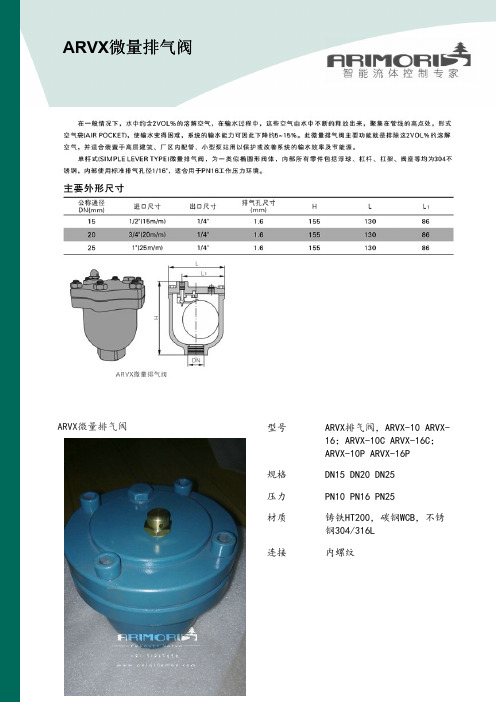
ARVX微量排气阀型号ARVX排气阀,ARVX-10ARVX-16;ARVX-10C ARVX-16C;ARVX-10P ARVX-16P 规格DN15DN20DN25压力PN10PN16PN25材质铸铁HT200,碳钢WCB,不锈钢304/316L 连接内螺纹ARVX 微量排气阀15160225902016026598251802651103220026511040220320125502503201256528032513080310385160100350385170125400430200150450430210200500560240250650690290300800800335350850880375简介ARVX型微量排气阀:本阀为一类似椭圆形阀体,内部所有零件包括浮球、杠杆、杠架、阀座等均为304不锈钢,内部使用标准排气孔径1/16",适合用于PN16工作压力环境。
作用在一般情况下,水中约含2VOL%的溶解空气,在输水过程中,这些空气由水中不断的释放出来,聚集在管线的高点处,形式空气袋(AIR POCKET),使输水变得困难,系统的输水能力可因此下降约5~15%。
此微量排气阀主要功能就是排除这2VOL%的溶解空气,并适合装置于高层建筑、厂区内配管、小型泵站用以保护或改善系统的输水效率及节能源。
结构尺寸规格DN G 出口尺寸排气口尺寸L L1H 151/2"1/4 1.613086155203/4"1/4 1.613086155251"1/4 1.613086155321-1/4"1/41.613086155安装要求1.于安装前,请先检查并清除主体内的杂物。
2.在阀前装一只闸阀,以便下次的安装维修。
阀如果安装于荫井内,应有足够空间以便容纳技术人员调整及维护工作。
3.若微量排气阀安装于室外,请注意阀门的保温,以防阀门内水结冰或冻裂阀门。

各种燃气阀门的介绍燃气阀门在燃气行业中占有重要的地位,阀门资讯建设部十分重视对燃气阀门的规范性建设,燃气阀门的行业标准有CJ3005-1992《城镇燃气用灰铸铁阀门的通用技术要求》、CJ3055-1995《城镇燃气用阀门的试验与检验》、CJ3056--1995《城镇燃气用球墨铸铁和铸钢制阀门的通用技术条件》、2002年6月又通过了《家用手动燃气阀门》的行业标准。
这些标准的制订和颁布规范了阀门行业、推动了燃气阀门的进步和发展、促进了燃气事业的发展;为研制、生产、使用单位提供了参考依据;提高了对燃气阀门与通用阀门区别的认识,保证了燃气阀门的安全裕度;受到了燃气同行们的欢迎一、RX系列油密封式旋塞阀上世纪八十年代,我国燃气主要是人工煤制气,蝶阀人工煤制气中有较多的杂质和"煤气胶",原来传统使用的单闸板契式水闸阀越来越不能适应燃气工况的需要,这类阀门普遍存在"关不严"和阀杆咬死的问题,我们参考日本技术研制而成的RX系列燃气用油密封式旋塞阀,解决了关不严和阀杆咬死的问题二、RZ系列燃气用平行双闸板闸阀随着燃气事业的发展和煤气厂的纷纷建立,需要较大甚至特大公称通径的燃气专用阀门,RZ系列燃气用平行双闸板闸阀针对人工煤气形成的问题给予一一解决,最大通径达1600mm1、平行双闸板闸阀在启闭过程中能刮去密封面上的"煤气胶",解决了煤气杂质黏附在密封面上影响阀门密封的大问题2、装有阀杆保护套,使阀杆不受"煤气胶"的侵蚀3、阀门下部带有排污孔侧盖,可以清扫落在阀腔底部的垃圾4、全通径设计流阻小,又能通清管器5、阀体采用特殊设计的"鼠笼框架式加强筋"减轻了阀门总体重量,增强了壳体强度和刚度6、RZ系列燃气闸阀壳体选用灰铸铁制造,价格低廉;第七、该系列闸阀带有全封闭的启闭指示器,使操作者清楚了解阀门所处状态真空阀门目录三、真空蝶阀类1、GI型系列高真空蝶阀2、GI-A型系列高真空蝶阀3、GI-C型系列高真空蝶阀4、GIQ型系列气动高真空蝶阀5、GIQ-A型系列气动高真空蝶阀6、GIQ-B型系列气动高真空蝶阀7、GIQ-AB型系列气动高真空蝶阀8、GID型系列电动高真空蝶阀9、GID-A型系列电动高真空蝶阀四、真空球阀类1、GU型系列真空(压力)球阀2、GUQ型系列气动真空(压力)球阀3、GUD型系列电动真空(压力)球阀五、其它真空阀类1、GW-J-T型系列高真空微调阀2、GM型系列高真空隔膜阀3、J611F活塞角座阀4、ZT-B系列管道阀5、CC-A型系列超高真空插板阀6、CCQ-A型系列气动超高真空插板阀GI 型系列高真空蝶阀是用来接通或切断真空管路中的气流。

阀门英文缩写(最全整理版)——按照字母排序air-compressor valve 空气压缩机阀门automatic cutout valve 自动切断阀门adjusting valve 调整阀, 调节阀admission valve 进气阀; 进浆阀air admission valve 进气阀air bleed(ing) valve 排气阀; 排气嘴air control valve 空调阀air cylinder valve 气筒阀air escape valve 泄气阀air inlet valve (=air intake valve) 进气阀; 进风阀air operated throttle motor 风动节流器, 风动节流阀马达air pilot valve 空气导向阀air pressure governor valve 风压调压阀air relay valve 空气中继阀air release valve (=air relief valve) 排气阀; 放空阀air reversing valve 空气换向阀air shut-off valve 空气关闭阀air signal reducing valve 空气信号减压阀air slide valve 空气分配阀air starting (control) valve 空气起动(控制)阀air straining check valve 空气滤尘止回阀air valve 空气阀air vent valve 气动调压阀, 排气阀air-actuated direction valve 气动控制换向阀air-compressor valve 空气压缩机阀门air-operated valve 气动换向阀air-vacuum proportional valve 空真比例阀air-vacuum two way valve 空真二位阀alarm valve 报警阀aligned grid valve 栅极中点校直的电子管阀Allan valve 阿伦滑阀altitude valve 【航空】高度阀(航空发动机汽化器的可调整阀) ammonia valve 【工】氨阀angle back-pressure valve 背压角阀angle globe valve 折角球形阀angle stop valve 弯形止阀, 折角止阀angle valve 角阀angle water valve 折角水阀annular ring valve 环形阀; 环状阀anti-g valve 【航空】防超重活门, 抗重力阀application pilot valve 作用导阀application valve 作用阀, 控制阀ashpan blower valve 灰盘吹风阀Askania valve 射流管阀atmos valve (=atmospheric valve) 大气阀, 空气阀; 放空阀autocontrol valve 自动控制阀automatic air valve 自动空气阀automatic brake valve 自动制动阀automatic control valve 自动控制阀automatic cutout valve 自动切断阀门automatic delivery control valve 自动输送控制阀automatic drain valve 自动排水阀automatic expansion valve (定压式)自动膨胀阀automatic gas sampling valve 自动气体进样阀automatic reducing valve 自动减压阀(高速制动机) automatic regulating valve 自动调节阀automatic spring loaded valve 自动弹簧阀automatic supplementary air valve 自动补充(空)气阀automatic unloading valve 自动卸载阀automatic valve 自动阀automatic water level valve 自动水准阀automatically operated valve 自动操作阀automatic-control servo valve 自动控制伺服阀auxiliary changeover valve 辅助切换阀auxiliary valve 辅助阀(暖汽调整阀用)back valve 回动阀, 止回阀, 逆止阀, 单向阀backflush valve 反冲阀backlash valve 无游隙阀门back-pressure valve 止回阀back-up valve 列车后端制动阀balance pressure reducing valve 平衡减压阀balance slide valve 平衡滑阀balance valve 平衡阀, 均压阀balanced distribution valve 平衡配气阀balanced safety valve 平衡式安全阀(可变动背压) ball check valve 止回球阀, 球形节流阀ball float valve 浮子阀, 浮球阀ball non-return valve 球形止回阀ball relief valve 球形安全阀ball safety valve 球形安全阀ball stop valve 球形止阀ball valve 球阀, 弹子阀ball-and-lever valve 杠杆球阀bell valve 钟形阀, 装料钟bellows valve 波纹管阀bellows-operated pilot valve 膜盒控制导阀, 膜盒导引阀bevel seat valve 斜座阀, 角阀biased valve 承载阀blast furnace gas valve 高炉煤气阀blast regulation valve 通风调节阀bleed valve 排出阀; 放泄阀bleeder valve 放液阀, 放水阀block valve 隔断阀blocking valve 闭塞阀blow valve 通风阀, 安全阀, 放空阀blow-down valve 排气阀blower drain valve 鼓风机放泄阀blower regulation valve 通风调节阀blower valve 鼓风机阀blow-off valve 排出[泄]阀, 放泄[空]阀, 喷放阀blowout valve 排气管, 排出阀boiler check valve 锅炉止回阀boiler feed valve 锅炉给水阀bonnet valve 帽状阀bottom drain valve 底部放泄阀bottom valve 底阀brake application magnet valve 电磁制动阀brake application valve 制动作用阀brake control valve 制动控制阀brake cylinder release valve 制动缸缓解阀, 制动缸放风阀brake metering valve 制动调节阀brake pipe compensating valve 制动管补偿阀brake release magnet valve 缓解电磁阀brake valve 制动阀brass valve 黄铜阀brass-fitted cast-iron valve 黄铜配制铸铁阀brass-trimmed valve 黄铜配制阀breather valve 通气阀, 呼吸阀breathing type safety valve 呼吸式安全阀(罐车)brine retaining valve 盐水箱保持阀bucket valve 活塞阀buffer change valve 缓变阀building block valve 积木式阀, 集成阀built-in check valve 内装式单向阀bullet valve 球阀buried valve with key 液下控制阀butterfly control valve 蝶形控制阀butterfly throttle valve 蝶形节流阀butterfly valve 蝶阀by-pass valve 旁通阀, 辅助阀, 回流阀by-path valve 旁通阀, 辅助阀, 回流阀caboose valve 守车阀cage type valve 笼形阀cam-operated valve 凸轮控制阀capless tyre valve 无帽胎阀car discharge valve 车辆放风阀car signal valve 车辆信号阀, 车辆放风阀cartridge inserted valve 筒式插装式阀, 插装阀cement valve 【机】水泥止回阀center valve 中心阀centre bypass valve 中间位置旁通的换向阀, M型机能换向阀centre spool valve 中心柱形阀centrifugal saw plate valve 离心机的圆盘保险(溢流)阀centrifugal type injection valve 离心式喷射阀change valve 活页阀;旋转阀, 转换阀;多向阀charge valve 充气阀, 加载阀, 加液阀charging check valve 充气止回阀charging valve 充气阀, 加载阀, 加液阀check valve 单向阀, 止回阀, 防逆阀;检验阀check-valve pump 止回阀配流泵chimney valve 烟道阀choker checkvalve 阻气单向阀cindervalve 卸灰阀Cineston controller brake valve 钦式控制制动联合阀(用于地下铁道) circulating-water valve 循环水阀circulation valve 环流阀clack valve 止回阀clapper valve 瓣阀clock valve 单向绞链阀closed center valve 中间位置封闭的阀(方向阀); 闭中心阀closed crossover valve 正遮盖的换向阀closed exhaust valve 密闭排气阀closed-type fuel valve 密闭形燃油阀closing valve 隔离阀, 节制阀, 隔断阀, 停汽阀clutch application valve 离合器作用阀clutch temperature adjusting valve 离合器温度调节阀coasting valve 滑行阀, 惯性运动阀coaxial valve 同轴管[阀]cold water stop valve 凉水止阀column shut-off valve 柱关闭阀column switching valve 柱转换阀column valve 柱阀combination sliding and rotary spool valve 又移动又旋转的圆柱滑阀combination valve 组合阀combined inlet-outlet valve 进出组合阀combined strainer and check valve 混合滤尘止回阀common slide valve 普通滑阀compensated flow control valve 带压力补偿的流量控制阀;调速阀compensated relief valve 平衡式溢流阀compensating air valve 补充空气阀, 补偿气阀, 平衡气阀compensating valve 补偿阀compensation valve 平衡阀, 补偿阀compression release valve 减压阀compression valve (减振器的)压缩行程阀concentric valve 同心阀condensate valve 凝结水阀condenser level control valve 凝汽器水位调节阀condenser relief valve 凝气器安全阀condenser valve 凝汽阀conductor‘s valve 车长阀, 紧急制动阀cone valve 锥形阀cone-way valve 单向阀conical seat valve 锥形座阀conical valve 锥形阀constant pressure expansion valve 恒压膨胀活门, 恒压膨胀阀constant pressure valve 恒压阀control air type reducing valve 控制空气型减压阀control air valve 控制空气阀control valve 控制阀, 调节阀;控制管, 调节管controllable check valve 可控单向[止回检验]阀controller pilot valve 控制器管制阀conversion valve 转换阀;转向阀Air valves空气阀门Angle Stop valves 角式截止阀Angle Throttle Valves 角式节流阀Angle Type Globe Valves门角式截止阀Ash valves 排灰阀Aspirating valves 吸(抽)气阀Auxiliary valves 辅助(副)阀Balance valves 平衡阀Bellows valves 波纹管阀Blowdown valves 泄料(放空,排污)阀Brake valves 制动阀Butterfly Type Non-slam Check蝶式缓冲止回阀Butterfly Valves with Gear Actuator蜗轮传动蝶阀Buttwelding valves 对焊连接阀Clamp valves 对夹式阀门Cock二通Combination valves 组合阀CQ Thread Ball ValvesCQ螺纹球阀Culvert valves 地下管道阀Deceleration valves 减速阀Diaphragm Valves隔膜阀Decompression valves 泄压阀Double Disc Flat Gate Valves双闸板平板闸阀Double Disk Parallel Gate Valves明杆平行式双闸板闸板Double Opening Exhaust Valves双口排气球Drainage valves 排水阀Electric Actuated Stop Valves电动截止阀Electric Actuated Wedge Gate Valves电动楔式闸阀Electric Double Disk Parallel Gate Valves电动平行式双闸板闸板Emergeny Cut-off Valves紧急切断阀Exhaust valves 排气阀Free Float Type Steam Trap浮球式疏水阀Flange Ball Valves法兰球阀Flange Gate Valves法兰闸阀Flange Globe Valves法兰截止阀Gauge Valves仪表阀Hand-operated valves 手动阀Hard Seal Butterfly Valves金属密封碟阀High Temperature Pressure Power Station Gate Valves高温高压电站闸阀High Temperature Pressure Power Station Globe Valves高温高压电站截止阀Hydraulic relay valves 液压继动阀High temperature valve 高温阀门hose valve 水带阀门Lift Check Valves升降式止回阀Lift Check Valves升降式止回阀Limit valves 限位阀Lining Ball Valves衬里球阀Lining Butterfly Valves衬里碟阀Lining Check Valves衬里止回阀Lining Cock衬里二通Lining Globe Valves衬里截止阀Lining T-Cock Valves衬里三通旋塞阀Liquid Indicator液位计LPG Pipe Fitting液化气管件Magnetic Co-operate Globe Valves磁耦合截止阀Magnetism Forle Pumps磁力泵Manual Oil Pumps Valves手摇油泵(阀)Meter Needle Type Globe Valves仪表针形截止阀Oblique Stop Valves直流式截止阀Parallel Slide Valves浆液阀Pintle valve 针形阀Piping Centrifugal Pumps管道离心泵Plunger valves 柱塞阀Pressure valve 压力(増压)阀Piping Pumps管道泵Piping Safety Valves管道安全阀Plunger Globe Valves柱塞截止阀Quick Draining Valves快速排污阀Restrictor Valves过流阀(或节流阀)Safety Valves安全阀Screw Pumps螺杆泵Scum Gate Valves排渣闸阀Solenoid valves 电磁阀Single Disc Flat Gate Valves单闸板平板闸阀Single Opening Exhaust Valves单口排气球Slurry Pumps泥浆泵Stop Valves截止阀Strainer过滤器Submerged Motor Pumps潜水电泵(排污泵) Swing Check Valves旋启式止回阀Swing Check Valves旋启式止回阀Tank Lorry Ball Valves槽车球阀T-Cock三通Thin Gate Valves薄型闸阀Throttle Valves节流阀Tiny Drag Slow Shut Check Valves微阻缓闭止回阀Triple (tee) valves 三通阀Two-way valves 二通阀Under Water Pumps液下泵Vacuum Pumps水力喷射器(真空泵)Vertical Lift Check Valves立式止回阀Wafer Check Valves对夹式止回阀Wafer plate valves 对夹蝶板阀Wafer Type Butterfly Valves with Rubber Itning对夹式衬胶蝶阀Waste Valves排污箱(阀)Water Seal Gate Valves水封闸阀Wedge Gate Valves楔式闸阀Y Type and Cylinder FiltersY型筒型过滤器2.零部件术语Axis Guide轴套Ball球、球芯Ball seat密封圈Blowdown Sealing Face启、阀件密封面Body阀体Bonnet阀盖Disc阀瓣Mut螺母。
Control Gate Valvewith 3-position pneumatic actuatorSample pictureThis manual is valid for the valve ordering number(s):640.. - .E.8 - . . . .The fabrication number is indicated on each product as per the label below (or similar):Explanation of symbols:Read declaration carefully before you start any other action!Keep body parts and objects away from the valve opening!Attention!Hot surfaces; do not touch!Product is in conformity with EC guidelines, if applicable!Loaded springs and/or air cushions are potential hazards!Disconnect electrical power and compressed air lines. Do not touch parts under voltage!Wear gloves!Imprint:Manufacturer VAT Vakuumventile AG, CH-9469 Haag, SwitzerlandWebsite Phone+41 81 771 61 61Fax+41 81 771 48 30Email***************Publisher VAT Vakuumventile AG, CH-9469 Haag, SwitzerlandEditor VAT Vakuumventile AG, CH-9469 Haag, SwitzerlandPrint VAT Vakuumventile AG, CH-9469 Haag, SwitzerlandCopyright © VAT Vakuumventile AG 2008No part of these Instructions may be reproduced in any way (photocopies, microfilms or anyother reproduction processes) nor may it be manipulated with electronic systems, duplicated ordistributed without written permission from VAT. Offenders are liable to pay damages.The original VAT firmware and updated state of the art versions of the VAT firmware areintended for use with VAT products. The VAT firmware contains a limited, time unlimited userlicense. The VAT firmware may not be used for purposes other than those intended nor is itpermitted to make copies of the VAT firmware. In particular, it is strictly forbidden to give copiesof the VAT firmware to other people.The use of trade names, brand names, trademarks, etc. in these Instructions does not entitlethird parties to consider these names to be unprotected and to use them freely. This is inaccordance with the meaning of the laws and acts covering brand names and trademarks.Contents:1Use of product (4)1.1Technical data (4)2Installation (5)2.1Installation into the system (5)2.2Connections (5)2.2.1Tightening torque for mounting screws on flanges (5)2.2.2Admissible forces (6)2.2.3Compressed air connection (7)2.2.4Actuator position (example) (8)2.2.5Compressed air connection by external solenoid (option) (8)2.2.6Electrical connection (9)3Operation (11)3.1Normal operation (11)3.1.1Adjustment of the intermediate position (11)3.2Operation under increased temperature (12)3.3Behavior in case of differential pressure (12)3.4Behavior in case of compressed air failure (12)3.5Behavior in case of power failure (12)4Trouble shooting (13)5Maintenance & repairs (13)5.1Preventive maintenance (14)5.1.1Procedures (15)6Drawing (17)7Spare parts (18)8Warranty (19)1 Use of productUse product for clean and dry indoor vacuum applications under the conditions indicated in chapter «Technical data» only! Other applications are only allowed with the written permission of VAT.Corrosive process gases may impact the performance of the product. Please contact VAT to assure that the product is compatible with the process gases used in your application.1.1 Technical dataPressure range DN 63 - 200: 1 x 10⁻⁸ mbar to 2 bar (abs)DN 250 - 400: to 1 bar (abs)Differential pressure on the closed gate DN 63 - 200: 2 bar in either directionDN 250 - 400: 1 bar in either directionMax. differential pressure at opening 30 mbarAdmissible temperature: Valve < 150°CActuator < 50°CCycles until first service 200000Supply voltage see label on solenoid control valvePower required 2 x 2,5 WContact rating of position indicator 5 A / 250 V AC, 3 A / 50 V DCCompressed air pressure 4 - 7 bar / 56 -98 psiFurther data according to VAT catalogue «Vacuum Valves 2008».2 Installation2.1 Installation into the systemThe valve seat side is indicated by the symbol: on the connection flange.2.2 Connections2.2.1 Tightening torque for mounting screws on flanges1. Mounting with centering ringTighten mounting screws of the flanges uniformly in crosswise order. Observe the maximum torque levels in the following table. Higher tightening torques deform the valve body and can lead to an improper function of the valve.2. Mounting with O-ring in groove2.2.2 Admissible forcesForces from evacuating the system, from the weight of other components, and from baking can lead to deformation of the valve body and to malfunction of the valve. The stress has to be relieved by suitable means, e.g. bellows sections. The following forces are admissible:lbf ft2.2.3 Compressed air connectionConnect air pressure to inputs '1' of the solenoids (internal thread R 1/8“, 1/8“ NPT for USA)Solenoid valve:Solenoid valve for impulse actuation:Make sure the emergency operation screws are in remote position (fully counter-clockwise)Note: Compressed air pressure (above atm): 4 - 7 bar / 56 -98 psiAttention:For proper function of the valve it is essential to use equal air pressure at OPEN -, CLOSE - and MIDDLE Pos. inlets. See table on page 6. Please consider that different solenoids, tube lengths and diameters can affect the air pressure.Compressed air may only be connected if- valve has been installed into the vacuum system - moving parts cannot be touched Use only clean, dry or slightly oiled air!For secure switching of solenoids, the inner diameter of the air connection tubes has to be: - 4 mm for lengths up to 1 m- 6 mm for lengths from 1 m to 5 m - 8 - 10 mm for lengths above 5 m2431524315schematic: schematic:2.2.4 Actuator position (example)Position A (Standard) Position B (Option)Note: For actuator position of your valve refer to the dimension diagram of your valve.2.2.5 Compressed air connection by external solenoid (option)Required solenoids: - Two 5/2 way valvesAir connections : - Adapter with internal thread R 1/8“ (1/8“ NPT for USA) mounted to the pipe thread screws 'A' and 'B' instead of the solenoids. The pipe thread screws have also the function of an orifice for air pressurereduction. They must not be removed or replaced.- L-type connection 'C' with internal thread R 1/8“ and integrated orifice fo r air pressure reduction (DN63 - 200: 1.4 mm, DN 250 - 400: 1.8mm)Apply compressed air pressure according the following table:2.2.6 Electrical connectionVerify that mains voltage matches voltage stated on the solenoid! Sockets for position indicator and solenoid are supplied with the valve.Do not touch electrical parts under voltage!Electrical power may only be connected if:valve has been installed into the vacuum systemmoving parts cannot be touchedWire solenoid and position indicator according to the following diagrams.V1 = impulse solenoid for main cylinder(next to pneumatics)V2 = impuse solenoid for auxiliary cylinderMV1 = solenoid coil for openingMV2 = solenoid coil for closingTo open energize the solenoids MV1 of V1 and V2 simultaneouslyTo close energize the solenoids MV2 of V1 and V2 simultaneouslyTo throttle energize the solenoids MV1 of V1and MV2 of V2 simultaneously3Operation3.1 Normal operationOperation is allowed only after proper installing procedure.3.1.1 Adjustment of the intermediate positionThe intermediate position can be adjusted (allen wrench 8mm) independently of the air pressure by means of the bolt screw 'M' (see also page 7 and picture below), on the face side of the auxiliary cylinder.Before moving the bolt screw 'M', open the locking screw (B) (allen wrench 2.5mm). After adjustment the intermediate position, fasten the locking screw (B).For easy adjustment, VAT is recommending to switching off the compressed air during adjustment of the intermediate position.A-side actuator: turning bolt screw 'M' clockwise moves the intermediate position to open B-side actuator: turning bolt screw 'M' clockwise moves the intermediate position to closeThe position indicator on the valve can be adjusted for the set intermediate position. Move valve with bolt screw 'M' to the desired position and than turn the screw (A) with a screwdriver size 2 on top of the position indicator box in either direction until the microswitch Lz switches. (Lz = position indicator for intermediate position)Aposition indicator for intermediate position3.2 Operation under increased temperatureSee «1.1 Technical data»3.3 Behavior in case of differential pressureNote: Do not open the valve, if the differential pressure on the gate is larger than 30 mbar.3.4 Behavior in case of compressed air failureValve closed: valve stays closed and leaktightValve open or Intermediate position: valve stays open or moves into closed (not leaktight) position, depending on the mounting position3.5 Behavior in case of power failureStandard solenoids: valve closesImpulse solenoids: valve moves to the position of last command and stays in this position4 Trouble shootingCompressed air?Electrical connection? Differential pressure Mechanical parts blocked? Check compressed air at solenoidsIs differential pressure < 30 mbar?Do not operate valve, while differential pressure is > 30 mbar. Equalize pressure first.Is valve cable connected properly?Mechanical parts blocked? (cleaning)Sealing surface gate GateO-ring Clean valve seat and gate!Check surface of seat and O-ringChange O-ring, if necessaryFlange seals leaktight?Bonnet seal leaktight?Screws at bonnet tightened properly?If you need any further information, please contact one of our service centers. You can find the addresses on our website: http://www.vat.ch5 Maintenance & repairsUnder clean operating conditions, the valve does not require any maintenance during the specified cycle life. Contamination from the process may influence the function and requires more frequent maintenance.Before carrying out any maintenance or repairs, please contact VAT. It has to be individually decided whether the maintenance/repair can be performed by the customer or has to be carried out by VAT. The fabrication number on the valvehas always to be specified.All supplies (e. g. compressed air, electrical power) must be disconnected for removal/installation of the valve from/into the system and for maintenance work.Even with disconnected supply, loaded springs and/or air cushions in cylinders can be potential hazards. Keep fingers and objects away from the valve opening!Products returned to VAT must be free of harmful substances such as e.g. toxical, caustic or microbiological ones. If products are radioactively contaminated, fill in the VAT form «Contamination and Radiation Report» and send it with the product. The form is available at VAT. The maximum values indicated in the form must not be exceeded.5.1 Preventive maintenanceThe numbers in brackets refer to the drawing on page 17.Note!The process environment of your application (i.e. corrosive gases, deposition on parts inside valve body) may suggest shorter preventive maintenance intervals than suggested below.Baking of the valve is highly recommended for contaminating processes. VAT offers customized heater box forseries 64 valves.For quick maintenance, VAT recommends to exchange the complete gate assembly in order to reduce thedowntime of the system.Warning! DN 160 – 400: Never remove the striking plate (22) of the ball guidance (18)!Recommended maintenance after every 100'000 cycles (after 50'000 cycles for DN 400)Clean gate O-ring (or to replace it, if necessary), clean the inside surfacesInspect the bonnet seal and inspect ball bearings and crank boltReplace all parts witch are per process caused corrosion or material pollution (recommended spare parts kit 'C')Recommended maintenance after every 200'000 cycles (after 100'000 cycles for DN 400)Additional to the 100'000 cycles maintenance interval, VAT recommends to clean and lubricate the ball bearings (replace it, if necessary), replace the locking balls, replace the crank bolt, inspect, clean and re-lubricate the ball guide plate (replace it if the balls have seized in the bushings), inspect, clean and re-lubricate the feedthrough O-ring (replace it if necessary) The following table refers to the procedures in the following chapter and the spare parts list on page 17.*) Definition of a cycle: Movement of the gate from open into closed or control position and back into open position5.1.1 Procedures1.Precondition for all maintenance workVent both valve chambersOpen gate valveShut off air supply and electrical power Disconnect all cables to the actuator2.Removal of the gate assembly (4) / Replacement of the crank bolt (6) / Replacement of the bonnet seal (3)Unfasten the bonnet screws (1)Remove the bonnet plate (2) and the bonnet seal (3)Pull the lever (17) a little bit out of the bonnet openingLoosen the hexagonal socket-head bolt (7) for the crank bolt (6)Remove the crank bolt (6), while lifting the gate assembly (4) a little bit if necessarySlide out the gate assembly (4) carefully from the body and put it on a clean workshop placeRe-assemble in reverse directionFasten the screws (1) crosswise with equal torque: 14 Nm (10 lbf ft) with DN 63 - 100 18 Nm (13 lbf ft) with DN 160 - 4003.Replacement of the gate O-ring (5)Put a suitable tool beneath the O-ring at the venting hole and lift the O-ring carefully out of the groove (take carethat the groove will not be damaged)Clean groove and sealing surfaceInstall new O-ring by pressing it crosswise uniformly into the groove. Make sure, the O-ring is not twisted (payattention to the seam of the O-ring)4.Replacement of the ball bearings (24)DN 63, DN 160 - 200: Replace the complete ball bearing assembly (DN 63: 1 pc, DN 160 - 200: 2 pcs) DN 100, DN 250 - 400: Replace each single ball bearing and pull out the its centre ring (4 pcs)5.Replacement of the locking balls (21)Put the gate assembly (4) carefully on a clean workshop place with the O-ring side to the bottomDN 63: Push center spring down and dismount two-piece circlip from the center bearing. Lift off ball guide plateDN 100 - 400: Unscrew the hexagonal nuts (19). Lift off counter plate (20) and ball guide plate (18) Remove the locking balls (21)6.Replacement of actuatorClose and lock valveRemove the position indicator box (8) from the actuator and unscrew the 2 hexagon bolts of the actuatorPull off actuator from the gear wheel of the feedthrough assembly (9). Take hold of the actuator on both sides ofthe actuator flange and use your thumb to push against the shaft of the feedthroughMake sure that rack of the actuator is in closed positionCheck whether valve is closed and properly lockedSet up actuator on gear wheel and shaft in a right angle to the valve. If the actuator cannot engage with the gearwheel, turn actuator under little pressure a few degrees counter-clockwise until it engages with the gear wheel For change into position A2 or B2, first unscrew the 2 hexagonal bolts of the feedthrough assembly and put theminto the bolt holes in the lateral axisTurn the actuator slightly back to the right angle position so that the 2 bolts can fit loosely in the threaded holesFasten the 2 bolts only when flange area of the actuator lies tightly on the actuator flange of the valveSet position indicator box (8) on actuatorAlign position indicator so that the 4 cylinder head screws will fit loosely in the threaded holes. Fasten screwsVerify the correct adjustment of the position indicator. In the position where the microswitch has switched, the valvemust be closed and locked7.Replacement of feedthrough O-ring (11)Remove gate assembly (4) as per items 1 and 2Remove actuator as per item 6Push the roll pin (12) out of the feedthrough shaft. Use VAT feedthrough assembling tool or a punch. Remove lever(17).Loosen the 2 screws of the feedthrough assembly (9)Slide out complete feedthrough assembly (9), carefully dismantle feed through assembly and remove thefeedthrough O-ring (11)6 Drawing7 Spare partsPlease specify the fabrication number of the valve (see yellow label on valve) when ordering spare parts. This is to ensure that the appropriate spare parts are supplied.8 WarrantyEach product sold by VAT Vakuumventile AG (VAT) is warranted to be free from the manufacturing defects that adversely affect the normal functioning thereof during the warranty period stated in VAT's «Terms of Sale» immediately following delivery thereof by VAT, provided that the same is properly operated under conditions of normal use and that regular, periodic maintenance and service is performed or replacements made, in accordance with the instructions provided by VAT. The foregoing warranty shall not apply to any product or component that has been repaired or altered by anyone other than an authorized VAT representative or that has been subject to improper installation or abuse, misuse, negligence or accident. VAT shall not be liable for any damage, loss, or expense, whether consequential, special, incidental, direct or otherwise, caused by, arising out of or connected with the manufacture, delivery (including any delay in or failure to deliver), packaging, storage or use of any product sold or delivered by VAT shall fail to conform to the foregoing warranty or to the description thereof contained herein, the purchaser thereof, as its exclusive remedy, shall upon prompt notice to VAT of any such defect or failure and upon the return of the product, part or component in question to VAT at its factory, with transportation charges prepaid, and upon VAT's inspection confirming the existence of any defect inconsistent with said warranty or any such failure, be entitled to have such defect or failure cured at VAT's factory and at no charge therefor, by replacement or repair of said product, as VAT may elect. VAT MAKES NO WARRANTY OR REPRESENTATION OF ANY KIND, EXPRESS OR IMPLIED, (INCLUDING NO WARRANTY OR MERCHANTABILITY), EXCEPT FOR THE FORE-GOING WARRANTY AND THE WARRANTY THAT EACH PRODUCT SHALL CONFORM TO THE DESCRIPTION THEREOF CONTAINED HEREIN, and no warranty shall be implied by law.Furthermore, the «Terms of sale» at the back of the price list are applicable.。
阀门部件中英文对照阀valve阀板valve deck plate阀板valve plate阀板式活塞泵valve deck plate type piston pump 阀板式活塞泵valve plate type piston pump阀瓣Disc阀操纵杆valve operating rod阀痤槽valve seat recess阀挡valve grid阀挡valve positioner阀挡valve stop阀导杆valve tail rod阀导向器valve guide阀盖bonnet阀盖衬套bonnet bush阀盖垫片bonnet gasket阀杆stem阀杆valve rod阀杆valve spindle阀杆端部尺寸Dimmension of valve stem end阀杆环stem ring阀杆螺母Yoke bushing Yoke nut阀杆填料stem packing阀杆头部尺寸Dimension of valve stem head阀簧valve spring阀簧压板valve spring plate阀控水锤泵valve-controlled hydraulic ram阀框架valve yoke阀门Valve阀门传动装置valve bandle set阀门和管件Valves and Fittings阀门盘根valve packing阀门手柄valve handle阀盘disc阀盘valve disc阀片Disc阀球valve ball阀驱动臂valve driving arm阀驱动臂valve motion arm阀式活塞valve type piston阀式活塞valve type bucket阀室式活塞泵valve box type piston pump阀室式活塞泵(美)valve pot type piston pump阀抬起装置valve lifting device阀体body阀体valve body阀箱valve box阀箱valve cage阀箱valve chest阀箱;阀限位器valve guard阀箱盖cover for valve box阀箱盖valve box cover阀箱式活塞泵(美)turret type piston pump阀形活塞泵valve type piston pump阀座Seat ring阀座valve carrier阀座valve seat(body seat)阀座;阀盘valve seat阀座环seat ring阀座密封嵌条sealing strip for valve seat法兰flange法兰堵头blind flange法兰端flange end法兰接头flange joint法兰连接紧固件(双头螺栓和螺帽)flange bolting 法兰密封面,法兰面flange facing法兰面加工flange facing finish法兰球阀Flange Ball Valves翻板阀Flap反冲盘Disc holder反向作用式减压阀Reverse acting reducing valve反向作用式减压阀Reverse acting reducing valve放空阀emptying valve放气阀air vent valve;vent valve放气阀;排气阀air evacuation valve放泄阀escape valve分置阀室式活塞泵separate valve box type piston pump 分置阀室式活塞泵(美)side pot type piston pump封闭式Seal type浮动式球阀Float ball valve浮球Ball float浮球阀Float Valve浮球式疏水阀Ball float steam trap浮球式疏水阀Free Float Type Steam Trap浮桶Bucket float浮桶式疏水阀Open bucket steam trap辅助(副)阀Auxiliary valves负荷率Rate of load condensate附加背压力Superimposed back pressure复位弹簧Returnning spring杠杆式Lever type杠杆式安全阀Lever and weight loaded safety valve杠杆式减压阀Lever reducing valve高温阀门High temperature valve高压阀门High pressure valve格兰密封gland隔离阀isolating valve隔膜Diaphragm隔膜阀diaphragm valve隔膜式控制阀diaphragm operated comtrol valve工作背压Operating back pressure工作温度Operating temperature工作温度Working temperature工作压差Operting differential pressure工作压力Operating pressure工作压力Working pressure公称通径Nominal diameter公称压力Nominal pressure固定式球阀Fixed ball valve关闭压力Lockup pressure关阀过冷度Subcooled temperature of close valve关阀温度Closing valve temperature管道安全阀Piping Safety Valves过冷度Subcoold temperature过流阀(或节流阀) Restrictor Valves喉径Throat diameter滑阀slide valve滑阀式回转活塞泵rotary piston pump with slide gate 滑阀型转子泵eccentric rotary pump with sliding sleeve 环形阀annular valve环形阀double beat valve换向阀selector valve换向阀shuttle valve回转滑阀活塞泵piston pump with rotary gate回座压力Re-seating pressure of a safety valve活塞昵减压阀Piston reducing valve活塞式阀piston valve活塞式阀;柱塞式阀plunger valve活塞式减压阀Piston reducing valve减速阀Deceleration valves减压比Pressure reducing ratio减压阀pressure reducing valve浆液阀Parallel Slide Valves角阀Angle Valve角阀isolation valve angle configuration角式Angie type角式节流阀Angle Throttle Valves角式截止阀Angle Stop valves铰链阀;片状阀flapper valve节流阀throttle valve节流阀choke valve节流阀;节流throttle结构长度Face-to-face dimension ;End-to-end dimension; Face-to-centre dimension 结构形式Type of construction截止阀Globe valve截止阀Shut-off Valve截止阀;关断阀shut-off valve截止式隔膜阀Globe diaphragm valve紧急切断阀Emergeny Cut-off Valves进气阀air intake valve进水阀;进口阀门inlet valve静态特性Static characteristics静态特性偏差Static characteristics derivation开阀过冷度Subcooled temperature of open valve开阀温度Opening valve temperature开启高度Lift壳体试验Shell test壳体试验压力Seal test pressure空气阀门Air valves快速排污阀Quick Draining Valves一、阀门种类英汉术语对照Airvalves空气阀门AngleStopvalves角式截止阀AngleThrottleValves角式节流阀AngleTypeGlobeValves门角式截止阀Ashvalves排灰阀Aspiratingvalves吸(抽)气阀Auxiliaryvalves辅助(副)阀Balancevalves平衡阀Bellowsvalves波纹管阀Blowdownvalves泄料(放空,排污)阀Brakevalves制动阀ButterflyTypeNon-slamCheck蝶式缓冲止回阀ButterflyValveswithGearActuator蜗轮传动蝶阀Buttweldingvalves对焊连接阀Clampvalves对夹式阀门Cock二通Combinationvalves组合阀CQThreadBallValvesCQ螺纹球阀Culvertvalves地下管道阀Decelerationvalves减速阀DiaphragmValves隔膜阀Decompressionvalves泄压阀DoubleDiscFlatGateValves双闸板平板闸阀DoubleDiskParallelGateValves明杆平行式双闸板闸板DoubleOpeningExhaustValves双口排气球Drainagevalves排水阀ElectricActuatedStopValves电动截止阀ElectricActuatedWedgeGateValves电动楔式闸阀ElectricDoubleDiskParallelGateValves电动平行式双闸板闸板EmergenyCut-offValves紧急切断阀Exhaustvalves排气阀FreeFloatTypeSteamTrap浮球式疏水阀FlangeBallValves法兰球阀FlangeGateValves法兰闸阀FlangeGlobeValves法兰截止阀GaugeValves仪表阀Hand-operatedvalves手动阀HardSealButterflyValves金属密封碟阀HighTemperaturePressurePowerStationGateValves高温高压电站闸阀HighTemperaturePressurePowerStationGlobeValves高温高压电站截止阀Hydraulicrelayvalves液压继动阀LiftCheckValves升降式止回阀LiftCheckValves升降式止回阀Limitvalves限位阀LiningBallValves衬里球阀LiningButterflyValves衬里碟阀LiningCheckValves衬里止回阀LiningCock衬里二通LiningGlobeValves衬里截止阀LiningT-CockValves衬里三通旋塞阀LiquidIndicator液位计LPGPipeFitting液化气管件MagneticCo-operateGlobeValves磁耦合截止阀MagnetismForlePumps磁力泵ManualOilPumpsValves手摇油泵(阀) MeterNeedleTypeGlobeValves仪表针形截止阀ObliqueStopValves直流式截止阀ParallelSlideValves浆液阀Pintlevalve针形阀PipingCentrifugalPumps管道离心泵Plungervalves柱塞阀Pressurevalve压力(増压)阀PipingPumps管道泵PipingSafetyValves管道安全阀PlungerGlobeValves柱塞截止阀QuickDrainingValves快速排污阀RestrictorValves过流阀(或节流阀) SafetyValves安全阀ScrewPumps螺杆泵ScumGateValves排渣闸阀Solenoidvalves电磁阀SingleDiscFlatGateValves单闸板平板闸阀SingleOpeningExhaustValves单口排气球SlurryPumps泥浆泵StopValves截止阀Strainer过滤器SubmergedMotorPumps潜水电泵(排污泵) SwingCheckValves旋启式止回阀SwingCheckValves旋启式止回阀TankLorryBallValves槽车球阀T-Cock三通ThinGateValves薄型闸阀ThrottleValves节流阀TinyDragSlowShutCheckValves微阻缓闭止回阀Triple(tee)valves三通阀Two-wayvalves二通阀UnderWaterPumps液下泵VacuumPumps水力喷射器(真空泵) VerticalLiftCheckValves立式止回阀WaferCheckValves对夹式止回阀Waferplatevalves对夹蝶板阀WaferTypeButterflyValveswithRubberItning对夹式衬胶蝶阀WasteValves排污箱(阀)WaterSealGateValves水封闸阀WedgeGateValves楔式闸阀YTypeandCylinderFiltersY型筒型过滤器二、零部件英汉术语对照AxisGuide轴套Ball球、球芯Ballseat密封圈BlowdownSealingFace启、阀件密封面Body阀体Bonnet阀盖Disc阀瓣Mut螺母Screw螺栓Sealing密封件Spring弹簧Stem阀杆StemMut阀杆螺母Stemseal填料WedgeDisc闸板三、规范技术英语术语对照Applicablemedium适用介质Applicabletemperature适用温度ButtClamp对夹Chemicalanalysis化学成份Connectingformat连接形式Doubledisc双闸板Flexibledisc弹性闸板Flange法兰Hoop卡箍Insidethread内螺纹Jacket夹套Mains电源Materialchemicalanalysisandmechanicalcapacity材料化学成份和机械性能materials材料Materialsformainparts主要零件材料Mechanicalcapacity机械性能Max.DischargingCapacity最大排水量Max.OperatingTemperature最高工作温度Max.AllowableTemperature最高允许温度Max.AllowablePressure最高允许压力Model型号Nameofparts零件名称nitrogen(N)氮Nominalbore公称通径NominalPressure公称压力Nozzle排气口Outsidethread外螺纹Oxidant氧化性介质Parallel平行Piping管路Piston活塞Reductant还原性介质Risingstem明杆Seal阀座,密封面Seattestingpressure压力气密封试验压力Socket卡套Specifications性能规范Singledisc单闸板Solid刚性Strenghtestingpressure强度试验压力Steam,condensate蒸汽,凝结水Stroke冲程,行程Water,oil,steam水,温度,气Wedge楔式Welding焊接四、材质术语英汉对照Atbasmetal镍铬钢Buna-Nrubber丁晴橡胶Castingaluminiumbrass铸铝黄铜Castingaluminiumbronze铸铝青铜Ceramicmetal陶瓷金属Chromelalloy镍铬合金CHRrubber氯晴橡胶Chrominm-molybdenum-vanadiumsteel铬钼钒钢Chromiumstainlesssteel铬不锈钢Chromium-molybdenumsteel铬钼钢Corrugationpad波形垫Cuprumalloy铜合金DuctileCastiron球墨铸铁Expandedgraphite柔性石墨FineSteelCastingiron优质碳素钢Fluorousrubber氟橡胶GrayCastiron灰铸铁Hayne’salloy钴铬钨合金Hightemperaturesteel高温钢Monel蒙乃尔合金Lowtemperaturesteel低温钢Nylon尼龙塑料Polytetrafluoroethylene(PTEF)聚四氟乙烯Polythene聚乙烯Purealuminium纯铝Purecupper纯铜Rubbergraphiteboard橡胶石墨板Springsteel弹簧钢Stainlessacid-resistingsteel不锈耐酸钢StainlessandGraphite不锈钢/石墨Stainlesssteel不锈钢SteelCastingiron碳素钢铸件ShellTestPressure壳体试验压力ServiceFluid工作介质。
液压机械英语液压专业词汇流体传动(水力)hydraulic power液压技术(水力学)hydraulics液力技术(流体力学;水动力学)hydrodynamics 气液技术(液压气动学)hydro-pneumatics运行工况operating working conditions额定工况rated working conditions极限工况limited working conditions瞬态工况instantaneous working conditions稳态工况steady-state working conditions许用工况acceptable working conditions连续工况continuous working conditions实际工况actual working conditions效率efficiency旋转方向direction of rotation公称压力nominal pressure工作压力working pressure进口压力inlet pressure出口压力outlet pressure压降pressure drop;differential pressure背压back pressure启动压力breakout pressure充油压力charge pressure开启压力cracking pressure峰值压力peak pressure运行压力operating pressure耐压试验压力proof pressure冲击压力surge pressure静压力static pressure系统压力system pressure控制压力pilot pressure充气压力precharge pressure吸入压力suction pressure调压偏差override pressure额定压力rated pressure耗气量air consumption泄漏leakage内泄漏internal leakage外泄漏external leakage层流laminar flow紊流turbulent flow气穴(现象)cavitations流量flow rate排量displacement额定流量rated flow供给流量supply flow流量系数flow factor滞环hysterics图形符号graphical symbol液压气动元件图形符号symbols for hydraulic and pneumatic components 流体逻辑元件图形符号symbols for fluid logic devices逻辑功能图形符号symbols for logic functions回路图circuit diagram压力时间图pressure time diagram功能图function diagram循环circle自动循环automatic cycle工作循环working cycle循环速度cycling speed工步phase停止工步dwell phase工作工步working phase快进工步rapid advance phase快退工步rapid return phase频率响应frequency response重复性repeat ability复现性reproducibility漂移drift波动ripple线性度linearity线性区linear region液压锁紧hydraulic lock液压卡紧hydraulic sticking变量泵variable displacement pump泵的控制control of pump齿轮泵gear pump叶片泵vane pump柱塞泵piston pump轴向柱塞泵axial piston pump法兰安装flange mounting底座安装foot mounting液压马达(发动机,电动机)hydraulic motor刚度stiffness中位neutral position零位zero position自由位free position缸cylinder有杆端rod end无杆端rear end外伸行程extend stroke内缩行程retract stroke缓冲cushioning工作行程working stroke负载压力induced pressure输出力force实际输出力actual force单作用缸single-acting cylinder双作用缸double-acting cylinder差动缸differential cylinder伸缩缸telescopic cylinder阀valve底板sub-plate油路块manifold block板式阀sub-plate valve叠加阀sandwich(plate)valve插装阀cartridge valve滑阀slide valve锥阀poppet valve阀芯valve element阀芯位置valve element position单向阀check valve液控单向阀pilot-controlled check valve 梭阀shuttle valve压力控制阀pressure control valve溢流阀pressure relief valve顺序阀sequence valve减压阀pressure reducing valve平衡阀counterbalance valve卸荷阀unloading valve直动式directly operated type先导式pilot-operated type机械控制式mechanically controlled type 手动式manually operated type液控式hydraulic controlled type流量控制阀flow control valve固定节流阀fixed restrictive valve可调节流阀adjustable restrictive valve 单向节流阀one-way restrictive valve调速阀speed regulator valve分流阀flow divider valve集流阀flow-combining valve截止阀shutoff valve球阀global/ball valve针阀needle valve闸阀gate valve膜片阀diaphragm valve蝶阀butterfly valve噪声等级noise level放大器amplifier模拟放大器analogue amplifier数字放大器digital amplifier传感器sensor阈值threshold(开始、开端、极限) 伺服阀servo valve四通阀four-way valve喷嘴挡板nozzle flapper液压放大器hydraulic amplifier颤振dither阀极性valve polarity流量增益flow gain对称度symmetry流量极限flow limit零位内泄漏null(quiescent) leakage 遮盖lap零遮盖zero lap正遮盖over lap负遮盖under lap开口opening零偏null bias零漂null drift阀压降valve pressure drop分辨率resolution频率响应frequency response幅值比amplitude(振幅) ratio传递函数transfer function管路flow line硬管rigid tube软管flexible hose工作管路working line回油管路return line补液管路replenishing line控制管路pilot line泄油管路drain line放气管路bleed line接头fitting;connection焊接式接头welded fitting扩口式接头flared fitting快换接头quick release coupling法兰接头flange connection弯头elbow异径接头reducer fitting流道flow pass油口port闭式油箱sealed reservoir油箱容量reservoir fluid capacity气囊式蓄能器bladder accumulator空气污染air contamination固体颗粒污染solid contamination液体污染liquid contamination空气过滤器air filter油雾气lubricator热交换器heat exchanger冷却器cooler加热器heater温度控制器thermostat消声器silencer双筒过滤器duplex filter过滤器压降filter pressure drop有效过滤面积effective filtration area公称过滤精度nominal filtration rating压溃压力collapse pressure填料密封packing seal机械密封mechanical seal径向密封radial seal旋转密封rotary seal活塞密封piston seal活塞杆密封rod seal防尘圈密封wiper seal;scraper组合垫圈bonded washer复合密封件composite seal弹性密封件elastomer seal丁腈橡胶nitrile butadiene rubber;NBR聚四氟乙烯Polytetrafluoroethylene;PTFE 优先控制override control压力表pressure gauge压力传感器electrical pressure transducer压差计differential pressure instrument液位计liquid level measuring instrument流量计flow meter压力开关pressure switch脉冲发生器pulse generator液压泵站power station空气处理单元air conditioner unit压力控制回路pressure control circuit(loop)安全回路safety circuit差动回路differential circuit调速回路flow control circuit进口节流回路meter-in circuit出口节流回路meter-out circuit同步回路synchronizing circuit开式回路open circuit闭式回路closed circuit管路布置pipe-work管卡clamper联轴器drive shaft coupling操作台control console(控制台)控制屏control panel避震喉compensator粘度viscosity运动粘度kinematical viscosity密度density含水量water content闪点flash point防锈性rust protection(quality)抗腐蚀性anticorrosive quality便携式颗粒检测仪portable particle counterPilot valve 先导阀Pilot-operated check valve 液控单向阀Sub-plate mount 板式安装Manifold block 集成块Pressure relief valve 压力溢流阀Flow valve 流量阀Throttle(扼杀)valve 节流阀Double throttle check valve 双单向节流阀Rotary knob 旋钮Rectifier plate 节流板Servo valve 伺服阀Proportional valve 比例阀Position feedback 位置反馈Progressive flow 渐增流量De-energizing of solenoid(螺线管)电磁铁释放二、介质类Phosphate ester (HFD-R) 磷酸甘油酯Water-glycol (HFC) 水-乙二醇Emulsion 乳化液Inhibitor缓蚀剂Synthetic lubricating oil 合成油三、液压安装工程Contamination 污染Grout 灌浆Failure 失效Jog 点动Creep爬行Abrasion 摩擦Extension(活塞杆)伸出Retraction(活塞杆)缩回Malfunction 误动作Pickling 酸洗Flushing 冲洗Dipping process 槽式酸洗Recirculation 循环Passivity 钝化Nitric acid 柠檬酸Argon 氩气Butt welding 对接焊Socket welding 套管焊Inert gas welding 惰性气体焊四、管接头Bite type fittings卡套式管接头Tube to tube fittings 接管接头union 直通接管接头elbow union 直角管接头tee union 三通管接头cross union 四通管接头Mal stud fittings 端直通管接头Bulkhead fittings 长直通管接头Weld fittings 焊接式管接头Female connector fittings 接头螺母Reducers extenders 变径管接头Banjo fittings 铰接式管接头Adjustable fittings/swivel nut 旋转接头五、伺服阀及伺服系统性能参数Dynamic response 动态频响DDV-direct drive valve 直动式伺服阀NFPA-National Fluid Power Association 美国流体控制学会Phase lag 相位滞后Nozzle flapper valve 喷嘴挡板阀Servo-jet pilot valve 射流管阀Dither 颤振电流Coil impedance 线圈阻抗Flow saturation 流量饱和Linearity 线形度Symmetry 对称性Hysterics 滞环Threshold 灵敏度Lap 滞后Pressure gain 压力增益Null 零位Null bias 零偏Null shift 零飘Frequency response 频率响应Slope 曲线斜坡液压系统(hydraulic system)执行元件(actuator)液压缸cylinder液压马达motor液压回路circuit压力控制回路pressure control流量(速度)控制回路speed control方向控制回路directional valve control安全回路security control定位回路position control同步回路synchronizing circuit顺序动作回路sequent circuit液压泵pump阀valve压力控制阀pressure valve流量控制阀flow valve方向控制阀directional valve液压辅件accessory普通阀common valve插装阀cartridge valve叠加阀superimposed valve;Sandwich plate valve 支承环Backup ring液压专业常用英语词汇一、阀类Solenoid valve (工业)电磁阀Check valve 单向阀Cartridge valve 插装阀Pilot valve 先导阀Pilot-operated check valve 液控单向阀Sub-plate mount 板式安装Manifold block 集成块Pressure relief valve 压力溢流阀Flow valve 流量阀Throttle valve 节流阀Double throttle check valve 双单向节流阀Rotary knob 旋钮Rectifier plate 节流板Servo valve 伺服阀Proportional valve 比例阀Position feedback 位置反馈Progressive flow 渐增流量De-energizing of solenoid 电磁铁释放二、介质类Phosphate ester (HFD-R) 磷酸甘油酯Water-glycol (HFC) 水-乙二醇Emulsion 乳化液Inhibitor缓蚀剂Synthetic lubricating oil 合成油三、液压安装工程Contamination 污染Grout 灌浆Failure 失效Jog 点动Creep爬行Abrasion 摩擦Retract(活塞杆)伸出Extension (活塞杆)缩回Malfunction 误动作Pickling 酸洗Flushing 冲洗Dipping process 槽式酸洗Re-circulation 循环Passivity 钝化Nitric acid 柠檬酸Argon 氩气Butt welding 对接焊Socket welding 套管焊Inert gas welding 惰性气体焊四、管接头Bite type fittings 卡套式管接头Tube to tube fittings 接管接头union 直通接管接头union elbow 直角管接头union tee 三通管接头union cross 四通管接头Mal stud fittings 端直通管接头Bulkhead fittings 长直通管接头Weld fittings 焊接式管接头Female connector fittings 接头螺母Reducers extenders 变径管接头Banjo fittings 铰接式管接头Adjustable fittings/swivel nut 旋转接头五、伺服阀及伺服系统性能参数Dynamic response 动态频响DDV-direct drive valve 直动式伺服阀NFPA-National Fluid Power Association 美国流体控制学会Phase lag 相位滞后Nozzle flapper valve 喷嘴挡板阀Servo-jet pilot valve 射流管阀Dither 颤振电流Coil impedance 线圈阻抗Flow saturation 流量饱和Linearity 线形度Symmetry 对称性Hysterics 滞环Threshold 灵敏度Lap 滞后Pressure gain 压力增益Null 零位Null bias 零偏Null shift 零飘Frequency response 频率响应Slope 曲线斜坡泵(本)体bump body无油轴承dry bearings油封oil seal扣环retainer ring定位梢locking pin前分流板front port plate凸轮环cam ring轮子rotor后分流板rear port plateO型环O ring端盖end cover六角沉头螺丝countersink hex-crew双头活塞twin piston弹簧spring单头活塞snap piston上盖top cover调整螺栓adjustable bolt螺帽screw nut半圆键woodruff key柱塞plug screw塞头螺丝plug screw排量cc/rev最高使用压力kgf/cm²(psi) (bar) 315kgf/cm²=4500psi 转速范围rpm零件表parts list塞头plug侧盖side cover调压柱塞spool调流侧盖side cover ( deliv, vol )调压本体pressure adj. bolt高压柱塞spool调压弹簧座spring post脚座型foot type轴shaft法兰座flange (lug)键沟keyway前分流套front port block后分流套rear port block后盖rear cover尺寸图dimensions性能曲线performance curves工作压力MPa (bar) 1MPa=10.2Kgf/cm²排量cm³/rev转速范围r/min输入信号电压(DC) (V)流量Qin流量(lpm)压力Pin频率Hz接通时间单位ms线圈耗电功率(A/V A max)压力范围(Pnom.: bar)流量(Qnom.: e/min)电-液比例换向调速阀proportional electro-hydraulic directional and flow control valves额定电流rated current零值电流quiescent current过载电流overload current线圈电阻coil resistance线圈电感coil inductance额定流量rated flow流量增益flow gain内漏internal leakage非线性度nonlinearity不对称度unsymmetry重叠lap压力增益pressure gain零偏null bias分辨率threshold频率特性frequency response电插头座electrical connector颤振dither伺服放大器servo-amplifier供油压力supply pressure回油压力return pressure耐压和破坏压力proof and burst pressure工作液fluids工作液清洁度filtration液压特性hydraulic characteristics静态特性static performance极性polarity空载流量特性no-load flow characteristic负载特性flow-load characteristics动态特性dynamic performance转移函数transfer function双喷嘴-挡板力反馈两级电液流量控制的伺服阀Double flapper-nozzle, force feedback, two stage electro-hydraulic flow control servo-valves 外形图external configuration结构原理图configuration幅频宽amplitude radio width相频宽phase lag width防尘圈bust wiper; Pin bust seal耐磨环(磨损环) wear ring ; slide ring; abrasion resistant ring滑阀slide valve活塞油封piston seal活塞杆油封rod seal垫片back up ring支承环support ring缓冲环buffer seal气缸垫cylinder washer断面图形section graphics夹布橡胶inter-cloth rubber乳化液emulsion公称尺寸nominal size允差tolerance杂质impurities凹凸缺陷convex and concave disfigurement边缘痕迹edge imprint沟槽尺寸dimension of slot替代substitute取代supersede导向带guide strip挡圈retaining ring简记abridged notation风动机械pneumatic machineries格来圈Gely ring斯特封Sterfin ring聚四氟乙烯青铜复合材料compound material of PTFE and bronze 安装尺寸installation dimension导向环guiding ring聚甲醛polyoxymethylene夹布胶木inter-cloth bakelite聚氨酯板/棒Polyurethane Bar梅花型联轴器弹性圈club-type elastic ring for joint-shaft皮碗packing bowl夹织物inter-fabrics螺纹插装阀cartridge valves电磁换向阀solenoid-operated valves压力控制阀pressure control valves调压范围spring ranges方向控制阀directional control valves阀芯结构形式type of pin锥阀poppet滑阀spool球阀ball流量控制阀flow control valves控制比例pilot ratios二位二通型two way two position锁紧扭矩mounting screw torque标准插封standard cavity标准阀块standard block标准线圈外形尺寸E-Coil shape dim.直动式溢流阀directly operated relief valves差动式溢流阀differential area relief valves先导式溢流阀pilot-operated relief valves组合溢流阀combined relief valves遥控溢流阀remote control relief valves油液清洁度filtration of oil双向溢流阀bi-directional relieve valves减压阀pressure reducing valves直动式顺序阀direct-acting sequence valves管式单向阀tubular check valves技术参数technical data开启压力cracking pressure压力补偿节流阀(固定节流孔)regulator pressure-compensated valves(fixed orifice)分流/集流阀flow divider/combiner valves节流controlled flow负载控制阀load control valves插式直动/先导溢流阀relief cartridge valves型号说明ordering code插式节流单向阀needle check cartridge valves碟式充液阀flange-clamped type, prefill valves油箱侧低压配管suction side pipe导压口接头pilot port adaptor油缸侧高压配管cylinder side pipe管式压力反馈型调速阀pressure-compensated flow control valves管式压力继电器pressure switch-pipe series叠加式压力继电器pressure switch-modular series叠加式电磁调速阀flow control sandwich-valves-solenoid operated管式/板式液压升降阀hydraulic lifting/lowering control valves额定电压rated voltage额定功率nominal power额定转速rotation speed力矩torque转向rotation direction三插hirschmann带嵌套conduit德意志插座integral Deutsch connector双插double spade圆形cylindrical手动卸荷manual override丁腈橡胶NBR氢化丁腈橡胶HNBR氟橡胶FKM硅橡胶PMQ/VMQ聚丙烯酸酯橡胶ACM乙丙橡胶EPDM/EPM夹布橡胶FAB聚氨酯PU热塑型聚氨酯TPU浇注型聚氨酯CPU聚四氟乙烯PTFE聚酰胺PA聚甲醛POM轴用密封(活塞杆) rod seals孔用密封(活塞)piston seals防尘密封件scrapers阀门英语名词术语(1)范围本标准适用于工业管道(或机器、设备)的通用阀门。
气动高压球阀是一种(球体)绕垂直于通道90度的阀门,它由活塞式双作用或单作用气动执行器和高压球阀组成,配用附件电磁阀、气源三联件、限位开关或电气阀门定位器,实现对工业管路中流体的截断
和开通。
气动气动高压球阀高压球阀
系列气体高压球阀
KHB
KHB系列气体高压球阀
KHB气体高压球阀是双(单)作用气动活塞式执行器与进口KHB高压球阀组成,是一种自动控制和遥控的新型阀门。
广泛的用于加气站、装罐车等高压管道,其连接形式分内螺纹(G/NPT)、焊接、卡套等。
气动高压球阀优点
1.流体阻力小,其阻力系数与同长度的管段相等。
2.结构简单、体积小、重量轻。
3.操作方便,开闭迅速,从全开到全关只要旋转90°,便于远距离的控制。
4.气动球阀通常配置各种附件,比如电磁阀、气源处理三联件、限位开关、定位器、控制箱等,以实现就地控制和远距离集中控制,在控制室里就可以控制阀门的开关,不需要跑到现场或者高空和危险地带来手动控制,在很大程度上节约了人力资源以及时间和安全性。
在全开或全闭时,球体和阀座的密封面与介质隔离,介质通过时,不会引起阀门密封面的侵蚀。
5.因为气动球阀动力源采用的是气体,一般为0.2-0.8MPa压力,相对比较安全。
气动球阀如果漏气的话,相对液动、电动来说,气体可以直接排出,对环境没有污染,同时具有较高的安全性。
执行器
气动执行器
气动
可以分为单作用执行器和双作用执行器。
(图为单作用式)
根据不同控制和要求可选择下列附件:
切断型附件:单电控电磁阀、双电控电磁阀、限位开关回讯器。
调节型附件:电气定位器、气动定位器、电气转换器。
气源处理附件:气源处理三联件。
手动机构:手操机构
执行器的开关和动作都通过气源来执行,叫做双作用。
单作用的开关动作只有开动作时气源驱动,而关的动作则需要弹簧开复位。
三段式锻造气动高压球阀
●阀体
阀体形式三段式锻造阀体
公称通径DN15~300mm、1/2"~12"
公称压力国标PN1.6、2.5、4.0、6.4、10.0、16.0、25.0MPa;美标ANSI150、300、600、900LB 法兰标准ANSI、GB、JB、HG等
连接形式法兰式、焊接式、螺纹式(适用于PN10MPa以内)
阀盖形式整体式
压盖型式螺栓压紧式
密封填料V型聚四氟乙烯填料、含浸聚四氟乙烯填料、石棉编织填料、柔性石墨
●阀内件
阀芯形式O型球体阀芯
流量特性快开特性
●执行机构
执行器型号GT、SR、ST、AT、AW系列单(双)作用气动执行器
供气压力0.4~0.7MPa
气源接口G1/4"、G1/8"、G3/8"、G1/2"
环境温度-20~+90℃
作用形式单作用执行机构:气关式(B)--失气时阀位开(FO);气开式(K)--失气时阀位关(FC)
双作用执行机构:气关式(B)--失气时阀位保持(FL);气开式(K)--失气时阀位保持(FL)
可配附件定位器、电磁阀、空气过滤减压器、保位阀、行程开关、阀位传送器、手轮机构等
注:如需详细执行器参数,请进入气动执行器页面进行查阅。
■主要零件材料
零件名称材料
阀体、阀盖WCB ZGOOCr17Ni14Mo2(CF3M)ZG1Cr18Ni9Ti(CF8)ZG1Cr18Ni12Mo2Ti(CF8M)球体2Cr13ZGOOCr17Ni14Mo2(CF3M)ZG1Cr18Ni9Ti(CF8)ZG1Cr18Ni12Mo2Ti(CF8M)阀杆2Cr13316L1Cr18Ni9Ti(304)1Cr18Ni12Mo2Ti(316)
阀座密封圈PTFE、碳素纤维+PTFE、对位聚苯
螺柱、螺母3535CrMoA(B7)
45(2H)
2Cr13(420)1Cr18Ni91Cr17Ni2(431)
密封填料V型PTFE、柔性石墨
■主要性能规范
公称通径
公称通径DN(mm)
DN(mm)DN15-3001/2"
1/2"~~12"
公称压力PN(MPa) 1.6 2.5 4.0 6.410.016.025.01503004006009001500
试验压力强度试验 2.4 3.75 6.09.615.024.037.5 3.17.810.215.323.138.4密封试验 1.76 2.75 4.47.0411.017.627.5 2.2 5.67.511.216.828.1低压气密试验0.5~0.7
适用介质水、油、蒸气、硝酸类(温度≤200℃)、醋酸类(温度≤200℃)
气动高压球阀安装注意事项
1)、安装前应按规定的信号(电或气)进行整机测试(防止因运输产生振动影响使用性能),合格后方可上线安装(接线按电动执行机构线路图)。
2)、准备与管道连接前,须冲洗和清除干净管道中残存的杂质(这些物质可能会损坏阀座和球)。
3)、在安装期间,请不要用阀的执行机构部分作为起重的吊装点,以避免损坏执行机构及附件。
.
4)、本类阀应安装在管道的水平方向或垂直方向。
5)、安装点附近的管道不可有低垂或者承受外力的现象,可以用管道支架或者支撑物来消除管线的偏
离。