2009【设备仕様书】(中文)
- 格式:xls
- 大小:1.75 MB
- 文档页数:4


2009 MKS Ambient Lighting Kit Manual Table of ContentsAMBIENT LIGHTING KIT INSTALLATION CONTENTSINSTALLATIONAmbient Lighting KitGENERAL PROCEDURESWire Splicing TechniquesINSTALLATIONLightingAmbient Lighting Kit ContentsPrepare Vehicle1.Review the Ambient Lighting Kit Contents.Ambient Lighting Kit2.Apply the parking brake.QUANTITY DESCRIPTION3.Turn the ignition key to the ‘‘ON’’ position and1DISTRIBUTION BOXmove the shift lever to ‘‘NEUTRAL’’.HARNESS ASSEMBLY•Turn the ignition key to the ‘‘OFF’’1CML MODULEposition.2LIGHT ROD1SWITCH 4.Remove the instrument panel finish panel1HARDWARE KIT applique.5.NOTE:LH floor console lower trim panel8.Remove the floor console finish panel.shown, RH floor console lower trim panel•With a non-marring tool, pry upward on the similar.floor console finish panel to release the Pull the middle and rear of the LH and RH retaining clips.floor console lower trim panels outward torelease the retaining clips.9.Remove the 4 floor console cup holder screws.6.Lift upward and open the storage compartmentlid.7.Remove the LH and RH floor console finishmouldings.•Lift upward on the floor console finishmouldings to release the retaining clips.10.Remove the floor console cup holder.11.NOTICE:To avoid damaging the selectorlever trim panel while performing this step,place a piece of cardboard onto the selectorlever trim panel.Detach the selector lever knob bezel.•With a non-marring tool, pry downward onthe selector lever knob bezel.Without Navigation14.Remove the 6 HVAC module screws.12.NOTE:LH side shown, RH side similar.Remove the selector lever knob.•Remove the 2 selector lever knob screws.15.Remove the HVAC module.•Disconnect the electrical connectors.With Navigation16.Remove the floor console front finish panel.•Remove the 4 floor console front finishpanel screws.13.Pull the selector lever trim panel toward therear of the vehicle to release the retaining clips.17.Remove the HVAC module.•Remove the 2 HVAC module screws.•Disconnect the electrical connectors.20.Remove the storage box trim ring.•Remove 2 screws.•Release the tabs.NOTE:LH shown RH similar.All18.Remove the floor console rear panel.•Pull straight rearward to disengage the clips.•Disconnect the electrical connectors.21.Remove the 2 screws and the floor consolestowage bin.•Disconnect the electrical connectors.19.Remove the 5 screws and the floor consolestowage bin door.22.Remove the RH lower instrument ing the supplied adhesive pad and three tieinsulator.straps mount the CML module to the wireharness below the center stack as shown below.•Remove three screws.•Disconnect interior lamp and electricalconnectors.•Remove the panel.Route HarnessNOTE:Avoid routing ambient lighting wires nearsharp edges and moving components.Install ModulesNOTE:Ensure the ambient lighting wires aresecure and do not interfere with vehicle operation. NOTE:Do not touch the adhesive, reducedadhesion may result.26.Route the 2-wire power harness and the light NOTE:Do not remove the clear protective film rod LED harness to the driver footwell area. from the back of the CML module.27.Route the switch harness and the harness23.Identify the distribution box, module with the containing the exposed LED ends to the consoledouble sided adhesive pad attached to the back.box area.Install Switch24.Remove the protective backing from theadhesive pad and secure the distribution box tothe LH side of the console as shown below.28.Locate and drill 11/16'' (17.5mm) hole In thefront of the console box below the USB port asshown below.29.File (2) Switch locating notches in the 11/16''32.Locate and drill 5/16'' (8mm) hole in the front(17.5mm) hole as shown below.of the console box below the audio port asshown below.30.Install the ambient lighting switch into theconsole box.33.Identify the exposed LED housing with thesingle lead.Install LEDNOTE:If this vehicle uses a liner in the cupholder, carefully mark the LED location onto theliner. Then remove the liner and use a 1/2'' hollowpunch to punch a hole in the liner to allow the LEDlight to pass through the liner. Re-install the linerwhen complete. One source of the hollow punch setis Harbor Freight, item # 03838 or use anequivalent 1/2'' hollow punch from another source.NOTE:Avoid driver distraction by locating the cupholder LED in the 7 o’clock position out of thedriver line of sight.31.Locate and drill 5/16'' (8mm) hole in the Rear34.Install the LED lens to the console box and thecup holder as shown below.assemble to the exposed LED housing with thesingle lead.35.Install the floor console stowage ing the assembled hardware attach the 12''light rod to the lower dash in the driver •Connect the USB port and cablefootwell as shown below.•Connect the ambient lighting switch•The silver end of the light rod is placed •Install the 2 screws outboard, closest to the vehicle door.•Locate clipsInstall Light Rods•secure tie straps.NOTE:One end of the light rod is silver the otherend is printed with the part number. The lightengine LED housing is attached to the part numberend of the light rod.38.Connect the light engine LED housingcontaining (2) wires to the light rod.•Attach light engine to the part number endof the light rod.36.Assemble (2) light rod retainer clips using partsfrom the hardware kit as shown below.•Attach saddle clip to J-nut using suppliedhardware.•Attach tie strap to saddle clip39.Route the remaining Light engine LED housingto the passenger footwell area.40.Locate and drill (2) 11/64'' (4.5mm) in the RHlower instrument panel insulator as shownbelow.43.Install the RH lower instrument panel insulator.•Connect the light engine LED housing tothe part number end of the light rod.•Connect interior lamp and electricalconnector.• Install the 3 screws.Power and Ground Connect i onsNOTE:For proper wire splicing techniques clickhere.44.Connect the Black ground wire from the41.Assemble rod clips to the RH lower instrumentambient lighting harness to the chassis ground panel insulator as shown below.point at the driver kick panel.ing assembled hardware attach 12'' light rod45.NOTE:A DVOM connected to the correct wireto the passenger hush panel as shown below.will show 0V when the park lamps switch in •Silver end of the rod is placed outboardthe OFF position , then show 12V when the closest to the door.when the park lamps switch in the ON position.A logic probe will show ground on the correctwire when the park lamps switch in the OFFposition, then show power when the park lampsswitch in the ON positionIdentify the Violet/White parking light circuitwire at the Smart Junction Box (SJB)Connector C2280E Pin 6.46.Connect the White wire from the ambientlighting harness to the violet/white park lampcircuit wire at the SJB Connector C2280E Pin6.53.NOTICE:Make sure to align the selectorlever holes in the selector lever trim panel tothe selector lever. Otherwise, damage to theselector lever trim panel may occur.Install the selector lever trim panel.•Connect the electrical connectors.54.Install the selector lever knob bezel over theshift lever.55.Install the selector lever knob.•Install the 2 selector lever knob screws. Install Trim•Attach the selector lever knob bezel.56.Install LED lens to cup holder.47.NOTE:Insure the ambient lighting wires aresecure and do not interfere with vehicleoperation.Use the supplied 4'' tie straps to secure theambient lighting harness wires.Without Navigation48.Install the HVAC module.•Connect the electrical connectors.•Install the 6 HVAC module screws.With Navigation49.Install the HVAC module.57.Install the floor console cup holder.•Connect the electrical connectors.•Install the 4 floor console cup holder •Install the 2 HVAC module screws.screws.50.Install the floor console front finish panel.58.Install the floor console finish panel.•Install the 4 floor console front finish panel59.Install the LH and RH floor console finishscrews.mouldings.All•Push downward on the floor console finishmouldings to secure the retaining clips. 51.Install the floor console stowage bin door.60.Close the storage compartment lid.•Install the 5 screws61.Install the instrument panel finish panel52.Install the floor console rear panel.applique.•Push inward to engage the clips.62.Place the gearshift lever in the PARK positionand release the parking brake.Proper Wire Splicing Techniques 1 GENERAL PROCEDURESProper SplicingTechniquesNOTE: Follow this procedure when a wire can bespliced without cutting the wire in half.1.Strip approximately two inches of insulationfrom the wire to be installed in the vehicle.4.Insert the new wire between the parted strands.If more than one wire is being spliced, wrapthem in opposite directions.2.On the vehicle wire to be spliced into, strip oneinch of insulation form the wire.NOTE: Use Rosin Core Mildly-Activated (RMA)Solder. Do not use Acid Core Solder.5.Wrap the new wire around one side of the splitstands, then wrap it around the other side.•Solder the connection.3.On the vehicle wire to be spliced into, separatethe strands to allow the new wire to be placedbetween the parted strands of wire.Proper Wire Splicing Techniques 2 GENERAL PROCEDURES(Continued)6.Wrap the connection with electrical tape so thetape covers the wires approximately two incheson either side of the connection.•Tape the wires together as shown in theillustration.NOTE: Use Rosin Core Mildly-Activated (RMA)Solder. Do not use Acid Core Solder.y the upper strand of wire to one side, thenlay the lower strand of wire to the other side asshown in the illustration.Splicing End to End Connections•Solder the wires together.NOTE: When both ends of the wire are cut, usethe end to end wire splicing procedure.NOTE: Follow the steps below for end to end wiresplicing.1.To make an end to end connection, start bystripping one inch of insulation from each ofthe wires. Part each wire into equal strands asshown in the illustration.4.Wrap the connection with electrical tape so thetape covers the wires approximately two incheson either side of the connection.2.Place the wires next to each other and twist theupper and lower strands together as shown.B C ACCESSORIZE YOUR VEHICLE A T : INSTALLATION INSTRUCTIONS - INTERIOR LED LIGHTING KITINSTRUCCIONESS DE INSTALACION- EL INTERIOR DEL KIT LA LUZ LED INSTRUCTIONS D’INSTALLATION - LED KIT DE LUMIÈRE EN INTERIEURQUICK REFERENCE CARDTARJETA RÁPIDE DE LA REFERENCIA Subject to alteration without notice5HVHUYDGDV PRGL¿FDFLRQHV WHFQLFDV 6RXV UpVHUYH GH PRGL¿FDWLRQV WHFKQLTXHVNOTE: ALIGN WITH RIB IN CASTING NOTE: ALINIE CON LAS COSTILLAS DE PLASTICOREMARQUE::ALIGNEZ AVEC LA NERVURE EN PLASTIQUECUPHOLDER TEMPLATEMOLDE SOSTENEDOR DE TAZA PORTE-TASSE GABARITSWITCH TEMPLATE MOLDE INTERRUPTORBOUTON ELECTRIQUE GABARITSTORAGE TEMPLATE MOLDE ALMACENAJE ENTREPOSAGE GABARITNOTE: VERIFY TEMPLATES ARE PRINTED TO SCALE NOTA: VERIFIQUE QUE ELMOLDE ESTE IMPRIMIDO A ESCALAREMARQUE: VERITAGZ QUE LES MODÈLE SONT IMPRIMER À L’ECHELLE3/4” 18.5mmNOTE: FILE NOTCH 2X2MM NOTE: LIGE CORTE 2X2MMREMARQUÉ: CLASSEZ ENTAILLE 2X2MMNOTE: DO NOT SCALE WHEN PRINTING NOTA: NO ESCALE AL IMPRIMIRREMARQUE: NE MESUREZ PAS EN IMPRIMANT2009 Taurus/Sable/TaurusX Ambient Lighting KitManual Table of ContentsAMBIENT LIGHTING KIT INSTALLATION CONTENTSINSTALLATIONAmbient Lighting KitGENERAL PROCEDURESWire Splicing TechniquesINSTALLATIONLightingAmbient Lighting Kit ContentsPrepare Vehicle1.Review the Ambient Lighting Kit Contents.Ambient Lighting Kit2.Turn the ignition key to the ‘‘ON’’ position.QUANTITY DESCRIPTION Apply the parking brake and move the shiftlever to ‘‘NEUTRAL’’.1DISTRIBUTION BOXHARNESS ASSEMBLY•Turn the ignition key to the ‘‘OFF’’1CML MODULE position.2LIGHT ROD3.Remove the floor shifter trim ring.1SWITCH1HARDWARE KITAll Vehicles6.Remove the center finish panel.•Pull outward on the panel to disengage theclips.•Disconnect the electrical connectors.7.Remove the driver side knee bolster.8.Remove the RH kick panel.•Remove the door scuff plate.•Remove the kick panel.4.Lift the armrest and remove the floor consolefinish panel.9.Remove the RH lower instrument panelinsulator.Taurus/Sable•Remove the 2 pin-type retainers.•Lower and remove panel.5.Remove the 2 center finish panel screws.Install Modules Install LEDNOTE:Do not touch the adhesive, reduced NOTE:If this vehicle uses a liner in the cup adhesion may result.holder, carefully mark the LED location onto theliner. Then remove the liner and use a 1/2’’ hollow NOTE:Do not remove the clear protective film punch to punch a hole in the liner to allow the LED from the back of the CML module.light to pass through the liner. Re-install the linerwhen complete. One source of the hollow punch set 10.Identify the distribution box, with the double is Harbor Freight, item # 03838 or use ansided adhesive pad attached to the back.equivalent 1/2’’ hollow punch from another source.11.Identify the CML module, with the clear NOTE:Avoid driver distraction by locating the cupprotective film attached to the back.holder LED in the 7 o’clock position out of thedriver line of sight.12.Apply the adhesive pad supplied in thehardware kit, directly to the clear protective17.Locate and drill 5/16’’ (8mm) hole in the Rear film of the CML module.cup holder as shown below.13.Remove the protective backing from theadhesive pad of both modules and secure bothof the modules to the lower air duct locatedbelow the center stack.•Secure with tie straps.Route HarnessNOTE:Avoid routing ambient lighting wires nearsharp edges and moving components.NOTE:Ensure the ambient lighting wires aresecure and do not interfere with vehicle operation.14.Route the 2-wire power harness to the driver18.Working from inside the console storage boxfootwell area.locate and drill 5/16’’ (8mm) hole in the frontof the console box next to the coin holder as 15.Route the light engine LED harness to the shown below.driver footwell area.16.Route the switch harness and the harnesscontaining the exposed LED ends to the consolebox area.Install Light Rods19.Route the Exposed LED housing with the singleharness wire to the 5/16’’ (8mm) hole next tothe coin holder.NOTE:One end of the light rod is silver the otherend is printed with the part number. The lightengine LED housing is attached to the part numberend of the light rod.20.Attach the LED lens to the exposed LEDhousing.21.Assemble (2) light rod retainer clips using partsfrom the hardware kit as shown below.•Attach saddle clip to J-nut using suppliedhardware.•Attach tie strap to saddle clip.ing the assembled hardware attach the 12’’light rod to the lower dash in the driverfootwell as shown below.•The silver end of the light rod is placedoutboard, closest to the vehicle door.•Locate clips•secure tie straps.26.Assemble rod clips to the RH lower instrumentpanel insulator as shown below.23.Connect the light engine LED housingcontaining (2) wires to the light rod.•Attach to the part number end of the lightrod.ing assembled hardware attach 9’’ light rodto the passenger lower instrument panelinsulator as shown below.•The silver end of the light rod is placedoutboard closest to the door.24.Route the remaining light engine LED housingto the passenger footwell area.25.Locate and drill (2) 11/64’’ (4.5mm) in the RHlower instrument panel insulator as shown28.Install the RH lower instrument panel insulator.below.•Connect the light engine LED housing tothe part number end of the light rod.• Install the 2 pin-type retainers.Install Switch — Taurus/Sable29.Locate and drill 11/16’’ (17.5mm) hole In thefloor console finish panel as shown below.30.File (2) Switch locating notches in the 11/16’’36.NOTE:A DVOM connected to the correct wire(17.5mm) hole as shown above.will show 0V when the park lamps switch in the OFF position , then show 12V when the 31.Install the ambient lighting switch into the floorwhen the park lamps switch in the ON position.console finish panel. A logic probe will show ground on the correct wire when the park lamps switch in the OFF Install Switch — TaurusXposition, then show power when the park lamps switch is in the ON position32.Locate and drill 11/16’’ (17.5mm) hole In theIdentify the Violet/White parking light circuit floor console finish panel as shown below.wire at the Smart Junction Box (SJB)Connector C2280E Pin 6.37.Connect the White wire from the ambientlighting harness to the violet/white park lamp circuit wire at the SJB Connector C2280E Pin 6.33.File (2) Switch locating notches in the 11/16’’(17.5mm) hole as shown above.34.Install the ambient lighting switch into the floorconsole finish panel.Power and Ground ConnectionsInstall TrimNOTE:For proper wire splicing techniques click 38.NOTE:Ensure the ambient lighting wires arehere.secure and do not interfere with vehicle operation.35.Connect the Black ground wire from theambient lighting harness to the chassis ground Use the supplied 4’’ tie straps to secure the point at the driver kick panel.ambient lighting harness wires.39.Install the RH kick panel.•Install the RH kick panel.•Install the door scuff plate.40.Install the driver side knee bolster.41.Install the center finish panel.•Connect the electrical connectors.•Push inward on the panel to engage theretaining clips.Taurus/Sable44.Install the floor console finish panel.42.Install the 2 center finish panel screws.•Connect the electrical connector.•Push the floor console finish panelAll Vehiclesdownward to engage the retaining clips.43.Install LED lens to cup holder.45.Close the storage compartment lid.46.Install the floor shifter trim ring.•Push the floor shifter trim ring downward.•Place the gearshift lever in the PARKposition.•Release the parking brake.ACCESSORIZE YOUR VEHICLE A T : / MERCURY /B C PERSONAL INJURYLESIONES PERSONALES RISQUE DE BLESSURE VEHICLE DAMAGE DANO DE VEHICULODOMMAGE AU VÉHICULE INCORRECT INCORRECTO INCORRECT CORRECT CORRECTO CORRECT SEE MANUAL VER MANUAL VOIR LE MANUELSubject to alteration without notice5HVHUYDGDV PRGL¿FDFLRQHV WHFQLFDV 6RXV UpVHUYH GH PRGL¿FDWLRQV WHFKQLTXHVINSTALLATION INSTRUCTIONS - INTERIOR LED LIGHTING KITINSTRUCCIONESS DE INSTALACION- EL INTERIOR DEL KIT LA LUZ LED INSTRUCTIONS D’INSTALLATION - LED KIT DE LUMIÈRE EN INTERIEURE。

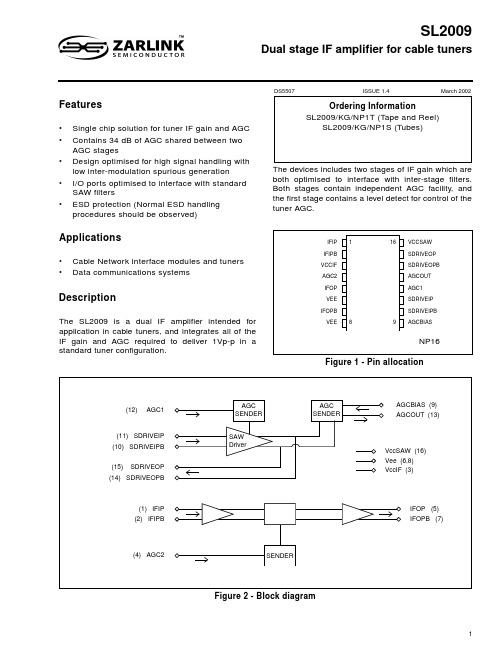
SL2009Dual stage IF amplifier for cable tunersDS5507ISSUE 1.4March 2002Figure 2 - Block diagramFeatures•Single chip solution for tuner IF gain and AGC •Contains 34 dB of AGC shared between two AGC stages•Design optimised for high signal handling with low inter-modulation spurious generation•I/O ports optimised to interface with standard SAW filters•ESD protection (Normal ESD handling procedures should be observed)Applications•Cable Network interface modules and tuners •Data communications systemsDescriptionThe SL2009 is a dual IF amplifier intended for application in cable tuners, and integrates all of the IF gain and AGC required to deliver 1Vp-p in a standard tuner configuration.The devices includes two stages of IF gain which are both optimised to interface with inter-stage filters.Both stages contain independent AGC facility, and the first stage contains a level detect for control of the tuner AGC.Figure 1 - Pin allocation元器件交易网Characteristics Units SAWF driver stageInput operating range30 - 50MHz Input NF, referred to 2kΩ4dBOPIP34dBV Gain14 - 28dBIF Amplifier stageInput operating range30 - 50MHz Input NF, referred to 2 kΩ6dBOPIP38dBV Gain20 - 40dBTable 1 - Quick reference dataFunctional DescriptionThe SL2009 is an IF amplifier intended primarily for application in cable tuners, and requiring a minimum external component count to integrate the IF gain, AGC facility and level detect.The pin allocation is contained in figure (1) and the block diagram in figure (2)SAWF driver stageIn normal application the IF output of the tuner, which is typically in the region of 30-50 MHz, is interfaced to input preamplifier of the SAWF driver stage, which is optimised for both signal handling and NF referred to 2 kΩ.The input preamplifier interfaces with the variable gain stage, which is under control of the first AGC sender and provides for 14 dB of gain control. The typical gain characteristic is contained in figure (3).The AGC stage then interfaces with the output buffer amplifier, which presents a balanced 50 Ω drive to the IF SAW filter and offers high signal handling to minimise intermodulation distortions.The SAWF amplifier also incorporates a level detect block whose output AGCOUT, can be used to control the gain of the SAWF amplifier or other gain stages in front of the SL2009. This AGC characteristic can be set up by a "current set" resistor connected between the AGCBIAS input and Vee. The typical characteristic curve for AGC set, output level under different AGCBIAS conditions is contained in figure (4).See figures (5) and (6) for SAW amplifier input and output impedances respectively.IF amplifier sectionIn normal application the output of the SAW filter is coupled differentially to the input preamplifier of the IF amplifier, which presents a differential 2 kΩ 3 pF load to the SAW filter and is optimised for both signal handling and NF. See figure (8) for IF amplifier input impedance.The input preamplifier, then interfaces with the variable gain stage which is under control of the second AGC sender and this provides for 20 dB of gain control. The typical AGC characteristic is contained in figure (7)The AGC output is then connected to the output driver stage, which presents a low differential output impedance, see figure (9) and is optimised for output signal handling.The typical key performance data at 5V Vcc and 25 deg C ambient are shown in the table entitled 'QUICK REFERENCE DATA'.Figure 3 - Typical SAWF driver stage AGC characteristicFigure 4 - AGCOUT characteristic versus AGCBIAS resistorFigure 5 - Typical SAWF driver input impedance, single-endedFigure 6 - Typical SAWF driver output impedance, single-endedFigure 7 - Typical IF amplifier stage AGC characteristicFigure 8 - Typical IF amplifier input impedance, single-endedFigure 9 - Typical IF amplifier output impedance, single-endedElectrical CharacteristicsTest conditions (unless otherwise stated)Tamb = -40˚ to 85˚C, V ee= 0V, V cc IF = 5V+-5%, V cc SAW =5V+-5%These characteristics are guaranteed by either production test or design. They apply within the specified ambient temperature and supply voltage unless otherwise stated.Characteristics pin min typ max units ConditionsSupply current3,165070mA Pin (3) VccIF and pin (16)VccSAW are isolated onchip.Operating frequency 3050MHzGain Flatness1dB Over specified output range.Excluding SAW filtercontributions. 8MHz B/W.See note (4)SAWF driverInput impedance10,112kΩDifferential, see figure (5)3pFNoise Figure46dB Tamb=27˚C, referred tosource impedance of 2 kΩconversion gain set at 28 dB Variation in NF with gainadjust-1dB/dBOutput referred IP33dBV Over specified gain range,see note (1) and (4)GainMaximum Minimum 25.58.53215dBdbVoltage conversion gain from2 kΩ differential source to 1kΩ//10 pF single-ended load,see note (4)Vagc1=1.5VVagc1=3.5VAGC monotonic from V ee toV cc. See Figure (3)Output impedance14,1550ΩSingle-ended, see figure (6) Output return loss14,159dBOutput limiting14,15 1.8Vp-p Single-ended into 1 kΩ // 10pF load 3rd Harmonic ofwanted output signal betterthan 10dBC.AGC1 Leakage current12-110110µA Vee<=Vagc1<=V cc-5050µA 1.5V<=Vagc1<=3.5V AGCOUT charging current131********µA Source and sinkAGCOUT voltage range 130.5 3.5V See note (3), max loadcurrent 50 µAAGC output level set See figure (4)Table 2 - Electrical CharacteristicsNotes:(1)Two output tones at 104 dB µ V within operating range (2) Two output tones at 108 dB µ V within operating range(3) When controlling external AGC the current load on AGCOUT should be minimised(4)For maximum performance, capacitive load should be resonated with appropriate inductance at chosen IFfrequency.Absolute Maximum RatingsAll voltages are referred to Vee at 0V, and VccIF=VccSAWIF amplifier Input impedance1,22k Ω Differential, see figure (8)3pFNoise Figure 46dBTamb=27˚C, referred to source impedance of 2 k Ω conversion gain set at 40 dBVariation in NF with gain adjust-1dB/dB Output referred IP35,75dBV With gains of 24dB and above, see note (2)4dBVWith gains from 20dB to 24dB, see note (2)GainMaximum Minimum3820dB dBVoltage conversion gain from 2 k Ω differential source to 1 k Ω // 15 pF single-ended load, see figure (7)Vagc2=1.0V Vagc2=4.25VAGC monotonic from V ee to V ccOutput impedance 5,725 Ω Single-ended, see figure (9)Output limiting5,71.8Vp-pSingle-ended into to 1 k Ω // 15 pF load. 3 rd Harmonic of wanted output signal better than 10dBC.AGC2 leakage current 4-110110 µ ACharacteristicspinmintypmaxunitsConditionsTable 2 - Electrical Characteristics (continued)Absolute Maximum RatingsAll voltages are referred to V ee at 0V, and V cc IF=VccSAWCharacteristics min max units conditions Supply voltage-0.37VAll I/O port DC offsets-0.3Vcc+0.3VStorage temperature-55150˚CJunction temperature150˚C32.2˚CPackage thermal resistance,chip to case108.1˚C/WPackage thermal resistance,chip to ambientPower consumption at 5.25V368mWESD protection2kV Mil-std 883B method 3015cat1Table 3 - Absolute Maximum RatingsFigure 10 - Evaluation Board SchematicInformation relating to products and services furnished herein by Zarlink Semiconductor Inc. or its subsidiaries (collectively “Zarlink”) is believed to be reliable.However, Zarlink assumes no liability for errors that may appear in this publication, or for liability otherwise arising from the application or use of any such information, product or service or for any infringement of patents or other intellectual property rights owned by third parties which may result from such application or use. Neither the supply of such information or purchase of product or service conveys any license, either express or implied, under patents or other intellectual property rights owned by Zarlink or licensed from third parties by Zarlink, whatsoever. Purchasers of products are also hereby notified that the use of product in certain ways or in combination with Zarlink, or non-Zarlink furnished goods or services may infringe patents or other intellectual property rights owned by Zarlink.This publication is issued to provide information only and (unless agreed by Zarlink in writing) may not be used, applied or reproduced for any purpose nor form part of any order or contract nor to be regarded as a representation relating to the products or services concerned. The products, their specifications, services and other information appearing in this publication are subject to change by Zarlink without notice. No warranty or guarantee express or implied is made regarding the capability, performance or suitability of any product or service. Information concerning possible methods of use is provided as a guide only and does not constitute any guarantee that such methods of use will be satisfactory in a specific piece of equipment. It is the user’s responsibility to fully determine the performance and suitability of any equipment using such information and to ensure that any publication or data used is up to date and has not been superseded. Manufacturing does not necessarily include testing of all functions or parameters. These products are not suitable for use in any medical products whose failure to perform may result in significant injury or death to the user. All products and materials are sold and services provided subject to Zarlink’s conditions of sale which are available on request.Purchase of Zarlink’s I 2C components conveys a licence under the Philips I 2C Patent rights to use these components in and I 2C System, provided that the system conforms to the I 2C Standard Specification as defined by Philips.Zarlink, ZL and the Zarlink Semiconductor logo are trademarks of Zarlink Semiconductor Inc.Copyright Zarlink Semiconductor Inc. All Rights Reserved. TECHNICAL DOCUMENTATION - NOT FOR RESALE For more information about all Zarlink productsvisit our Web Site at元器件交易网。

AS-1801贴片机规格AS-1801-001(1/19)12.适用元件(1)适用元件大小: 0.4 × 0.2 ∼ 3.2 × 1.6mm厚度: Max. 2.0mm引脚间距 : 0.3mm间距以上引脚宽: Min. 0.1mm引脚长: Min. 0.2mm注 : 根据机械的特性及形状等,有无法使用的元件。
适用参考元件•圆筒元件电阻器、电容器、二极管、其他类似形状元件•方形元件电阻器、层叠电容器、线圈、片状陶瓷滤波器、其他类似形状元件•带引脚元件微型晶体管、小功率晶体管、滤波器、LED、二极管、线圈、其他类似形状元件• BGA/CSP元件(选购件)BGA、CSP、LGA、其他类似形状元件大小: Max. 3.2 × 3.2mm球体直径 : Min. φ 0.13mm球体间距 : 0.25mm间距以上(2) 包装规格编带元件 JIS规格及相当于此类规格的产品•纸质编带元件(宽8mm)•压纹编带元件(宽4mm、8mm)•带盘外径 : φ 382mm以下注 : 编带的部分尺寸有限制。
并且根据机械的特性,有无法使用的编带。
13.安装头 可装备4个安装头/4个横梁吸嘴 : 各安装头最多15个φ3mm以下的吸嘴14.吸嘴保管数 高速吸嘴储料器最多可保管16个(8个×2排)最多24个(选购件8个×3排)15.搭载送料器数 最多40台(20台带式送料器×2个送料器安装台)注 : (a) 请使用SIGMA-F8用带式送料器。
使用SIGMA-G4/G5用、GXH系列用带式送料器时,部分使用条件有限制。
(b)不能使用其他装置的带式送料器及散装送料器。
16.线路板程序数据的存储量 最大步骤数 : 20,000 步骤/机种(重复图形时)最大存储机种数 : 100 机种注 : 根据对应机种的线路板程序数据容量不同,有所限制。
17.线路板程序数据的编辑、输入和输出 •用主机触摸屏操作、键盘/指点杆鼠标(选购件) 进行编辑。

案件№11
苛 性 ソ ー ダ(20%) 仕 様 書
二見浄化センター
1 品名
苛性ソーダ溶液(20%)
2 品質
⑴ 20%の水酸化ナトリウム(NaOH)
⑵ 日本ソーダ工業会 液体苛性ソーダ JSIA 01-1998 1種
3 荷姿及び搬入方法
⑴ タンクローリー圧送搬入
4 年間予定数量(二見浄化センター)
600,000 ㎏(液体重量)
5 納入仕様その1(二見浄化センター)
⑴ 品質保証について
ア 製品安全データシート(MSDS)を提出のこと。
イ 上記品質を保証するため、納入品ごとに分析表を提出すること。
万一品質不良等が生じたときは、市職員の指示に従い無償にて、速やかに取り替えること。
ウ 規格等が変更になった場合は、納入先の市職員まで随時連絡を行うこと。
⑵ 搬入について
ア 搬入については、業務に支障のないよう、納期等について遺漏のないよう注意すること。
イ 搬入時間帯は、市職員の指示がない限り午前9時より午後4時までとする。
ウ 搬入手順を遵守し、荷降作業手順書・漏洩事故防止手順書・漏洩時緊急マニュアル・緊急連絡表を提出のこと。
エ 1回の発注量は、通常6㎥とし、発注後3日以内に納入のこと。
⑶ その他
ア その他、疑義を生じた場合は、市職員に連絡すること。
イ 本市及び第3者に損害を与えた場合は、請負人の責にて弁償すること。
ウ 納入場所:明石市二見町南二見3番 二見浄化センター
汚泥棟1階 タンク容量:9㎥+10㎥の各々独立した2タンク
6 納入期間
平成25年4月1日~平成26年3月31日。
MultimediaDocument Part Number: 404160-001March 2006This guide explains how to use the multimedia hardware and software features of the computer. Multimedia features vary according to the model and software you selected.Contents1Multimedia hardwareUsing the optical drive. . . . . . . . . . . . . . . . . . . . . . . . . . . 1–2 Identifying the installed optical drive . . . . . . . . . . . . 1–2Inserting an optical disc. . . . . . . . . . . . . . . . . . . . . . . 1–3Removing an optical disc (with power). . . . . . . . . . . 1–4Removing an optical disc (without power) . . . . . . . . 1–5 Using the audio features. . . . . . . . . . . . . . . . . . . . . . . . . . 1–6 Using the internal microphone (select modelsonly) or the audio-in (microphone) jack . . . . . . . . . . 1–9Using the audio-out (headphone) jack. . . . . . . . . . . . 1–9Adjusting the volume. . . . . . . . . . . . . . . . . . . . . . . . 1–10 Using the video features. . . . . . . . . . . . . . . . . . . . . . . . . 1–11 Using the external monitor port. . . . . . . . . . . . . . . . 1–11Using the S-Video-out jack(select models only). . . . . . . . . . . . . . . . . . . . . . . . . 1–12 2Multimedia softwareIdentifying preinstalled multimedia software . . . . . . . . . 2–2Installing multimedia software from a CD(select models only). . . . . . . . . . . . . . . . . . . . . . . . . . . . . 2–2Using multimedia software . . . . . . . . . . . . . . . . . . . . . . . 2–3Protecting playback . . . . . . . . . . . . . . . . . . . . . . . . . . . . . 2–4Protecting the CD or DVD write process. . . . . . . . . . . . . 2–4Changing DVD region settings . . . . . . . . . . . . . . . . . . . . 2–5Observing the copyright warning. . . . . . . . . . . . . . . . . . . 2–6 Multimedia ii1Multimedia hardware The computer includes the following multimedia hardwarecomponents:■Optical drive■Internal microphone and audio-in (microphone) jack■Audio-out (headphone) jack■External monitor port■S-Video-out jack✎Components included with your computer may vary by geographical region and by model. The illustrations in thischapter identify the standard features included in mostcomputer models.Multimedia1–1Multimedia hardwareUsing the optical driveThe optical drive allows you to play, copy, and create CDs orDVDs, depending on the type of installed drive and installedsoftware.✎Your computer may look slightly different from theillustrations in this chapter.Identifying the installed optical driveTo view the type of optical drive installed in the computer:»Select Start > My Computer.The type of optical drive installed in the computer isdisplayed under Devices with Removable Storage.1–2MultimediaMultimedia hardwareMultimedia 1–3Inserting an optical disc1.Turn on the computer.2.Press the release button 1 on the drive bezel to release the media tray.3.Pull out the tray 2.4.Hold the CD or DVD by the edges to avoid touching the flat surfaces, and position the disc over the tray spindle, with the label side up.✎If the tray is not fully accessible, tilt the disc carefully toposition it over the spindle.5.Gently press the disc 3 down onto the tray spindle until the disc snaps into place.6.Close the media tray.✎After you insert a disc, a short pause is normal. If you have not selected a default media player, an AutoPlay dialog box opens. Itprompts you to select how you want to use the media content.1–4MultimediaMultimedia hardwareRemoving an optical disc (with power)If the computer is running on external or battery power:1.Turn on the computer.2.Press the release button 1 on the drive bezel to release the media tray, and then pull out the tray 2.3.Remove the disc 3 from the tray by gently pressing down on the spindle while lifting the outer edges of the disc. Hold the disc by the edges and avoid touching the flat surfaces.✎If the tray is not fully accessible, tilt the disc carefully as youremove it.4.Close the media tray and place the disc in a protective case.Multimedia hardwareMultimedia 1–5Removing an optical disc (without power)If external or battery power is not available:1.Insert the end of a paper clip 1 into the release access in the front bezel of the drive.2.Press in gently until the tray is released, and then pull out the tray 2.3.Remove the disc 3 from the tray by gently pressing down on the spindle while lifting the outer edges of the disc. Hold the disc by the edges and avoid touching the flat surfaces.✎If the tray is not fully accessible, tilt the disc carefully as youremove it.4.Close the media tray and place the disc in a protective case.1–6MultimediaMultimedia hardwareUsing the audio featuresThe following illustrations and tables describe the audio features of the computer.✎Refer to the illustration that most closely matches yourponent Description 1Volume mute light On: Computer sound is off.2Volume mute button T urns off computer sound.3Volume down button Decreases computer volume.4Volume up buttonIncreases computer volume.(Continued)Multimedia hardwareComponent Description5Internal microphone Records sound.6Audio-out (headphone) jack Connects optional powered stereospeakers, headphones, ear buds, aheadset, or television audio.7Audio-in (microphone) jack Connects an optional headsetmicrophone or stand-alonemicrophone.8Speakers (2)Produce computer sound. Multimedia1–71–8MultimediaMultimedia hardware Component Description 1Audio-out (headphone) jack Connects optional powered stereospeakers, headphones, ear buds,headset, or television audio.2Audio-in (microphone) jack Connects an optional headsetmicrophone or standalonemicrophone.3Speakers (2)Produce computer sound.Multimedia hardware Using the internal microphone(select models only) or the audio-in (microphone) jackThe computer is equipped with an internal monaural microphoneand a stereo (dual-channel) microphone jack that supports astereo array or a monaural microphone. Using sound recordingsoftware with external stereo microphones allows for stereorecording and stereo playback.When connecting a microphone to the microphone jack, use amicrophone with a 3.5-mm plug.✎When an external microphone is connected to the computer, the computer internal microphone is disabled.Using the audio-out (headphone) jackÅWARNING: To reduce the risk of personal injury, adjust the volume before putting on headphones, ear buds, or a headset.ÄCAUTION: To prevent possible damage to an external device, do not plug a singe sound channel (monaural) connector into the headphonejack.In addition to connecting headphones, the headphone jack is usedto connect the audio input function of an audio/video device suchas a television or VCR.When connecting a device to the headphone jack, use only a3.5-mm stereo plug.✎When a device is connected to the headphone jack, the internal speakers are disabled.Multimedia hardwareAdjusting the volumeYou can adjust the volume using the following controls:■Computer volume buttons:❏To mute or restore volume, press the volume mute button.❏To decrease the volume, press the volume down button.❏To increase the volume, press the volume up button.■Microsoft Windows volume control:1.Click the Volume icon in the notification area, at the farright of the taskbar.2.Increase or decrease the volume by moving the slider upor down. Select the Mute check box to mute the volume.– or –1.Double-click the Volume icon in the notification area.2.In the Master V olume column, increase or decrease thevolume by moving the Volume slider up or down. Youcan also adjust the balance or mute the volume.If the V olume icon is not displayed in the notification area,follow these steps to place it there:1.Select Start > Control Panel > Sounds, Speech, andAudio Devices > Sounds and Audio Devices.2.Click the Volume tab.3.Select the Place volume icon in the taskbar check box.4.Click Apply.■Application volume control:V olume can be adjusted within some applications.Multimedia hardwareUsing the video featuresThe computer includes the following video features:■External monitor port that connects a television, monitor, or projector■S-Video-out jack (select models only) that connects a range of advanced video componentsUsing the external monitor portThe external monitor port connects an external display device,such as an external monitor or projector, to the computer.To connect a display device, connect the device cable to theexternal monitor port.✎If a properly connected external display device does not display an image, press fn+f4 to transfer the image to thedevice.Multimedia hardwareUsing the S-Video-out jack(select models only)The 7-pin S-Video-out jack connects the computer to an optionalS-Video device such as a television, VCR, camcorder, overheadprojector, or video capture card.The computer can support one S-Video device connected to theS-Video-out jack, while simultaneously supporting an image onthe computer display or on any other supported external display.✎To transmit video signals through the S-Video-out jack, you need an S-Video cable, available from most electronicsretailers. If you are combining audio and video functions,such as playing a DVD movie on your computer and displayingit on your television, you also need a standard audio cable,available from most electronic retailers, to connect to theheadphone jack.Multimedia hardwareTo connect a video device to the S-Video-out jack:1.Plug one end of the S-Video cable into the S-Video-out jackon the computer.2.Plug the other end of the cable into the video device, asinstructed in the documentation included with the device.3.Press fn+f4 to switch the image between display devicesconnected to the computer.✎If the S-Video-out jack on the computer is not accessible because the computer is docked into an optional dockingdevice (select models only), connect the S-Video cable to theS-Video-out jack on the docking device.2Multimedia software The computer includes preinstalled multimedia software. Somemodels may be shipped with additional multimedia software on an optical disc.Depending on the hardware and software included with thecomputer, the following multimedia tasks may be supported:■Playing digital media, including audio and video CDs, audio and video DVDs, and Internet radio■Creating or copying data CDs■Creating, editing, and burning audio CDs■Creating, editing, and burning a video or movie to a DVD or video CD✎For details about using software included with the computer, refer to the software user guides. These guides may beprovided on CD or as online Help files within the specificapplication. User guides may also be found on the softwaremanufacturer’s Web site.Multimedia softwareIdentifying preinstalled multimedia softwareTo view and access the preinstalled multimedia software on thecomputer:»Select Start > All Programs.✎You can also reinstall multimedia software on the computer.Select Start > All Programs > Software Setup.Installing multimedia softwarefrom a CD (select models only)To install multimedia software from a CD included with thecomputer:1.Insert the multimedia software CD into the optical drive.2.When the installation wizard opens, follow the installationinstructions on the screen.3.Restart the computer if prompted.Repeat the installation procedure for all multimedia software onCD that you want to install.Multimedia softwareUsing multimedia softwareTo use the multimedia software installed on the computer:1.Select Start > All Programs, and then open the multimediaprogram you want to use. For example, if you want to useWindows Media Player to play an audio CD, selectWindows Media Player.✎Some programs may be located in subfolders.2.Insert the media disc, such as an audio CD, into the opticaldrive.3.Follow the instructions on the screen.– or –1.Insert the media disc, such as an audio CD, into theoptical drive.An AutoPlay dialog box opens.2.Click the multimedia task you want to perform from thelist of tasks for each installed multimedia program.✎The AutoPlay dialog box allows you to select a defaultmultimedia program for the media disc. After you select aprogram from the list, click the Always do the selectedaction box.3.Click OK.Multimedia softwareProtecting playbackTo prevent the loss of playback or playback quality:■Save your work and close all open applications beforeplaying a CD or a DVD.■Do not connect or disconnect hardware while playing a disc.To prevent the loss of playback while the computer is inWindows, do not initiate standby or hibernation while playing adisc. If standby or hibernation is initiated while a disc is in use,you may see the warning message “Putting the computer intohibernation or standby might stop the playback. Do you want tocontinue?” If this message is displayed, click No. After youclick No:■Playback may resume.– or –■Playback may stop and the screen may clear. To return to playing the CD or DVD, press the power button and thenrestart the disc.Protecting the CD or DVD write processÄCAUTION: To prevent loss of information or damage to a disc:■Before writing to a disc, connect the computer to a reliable external power source. Do not write to a disc while the computer is runningon battery power.■Before writing to a disc, close all open programs except the disc software you are using.■Do not copy directly from a source disc to a destination disc or froma network drive to a destination disc. Instead, copy from a sourcedisc or network drive to your hard drive, and then copy from yourhard drive to the destination disc.■Do not use the computer keyboard or move the computer while the computer is writing to a disc. The write process is sensitive tovibration.Multimedia softwareChanging DVD region settingsMost DVDs that contain copyrighted files also contain regioncodes. The region codes help protect copyrights internationally.You can play a DVD containing a region code only if the regioncode on the DVD matches the region setting on your DVD drive.If the region code on a DVD does not match the region setting onyour drive, the following message is displayed when you insertthe DVD: “Playback of content from this region is not permitted.”To play the DVD, you must change the region setting on yourDVD drive. DVD region settings can be changed through theoperating system or through some DVD players.ÄCAUTION: The region settings on your DVD drive can be changed only 5times.■The region setting you select the fifth time becomes the permanent region setting on the DVD drive.■The number of allowable region changes remaining on the drive is displayed in the Changes remaining box on the DVD Regiontab. The number in the box includes the fifth and permanentchange.Multimedia softwareTo change DVD settings through the operating system:1.Select Start > My Computer.2.Right-click in the window and select Properties > Hardwaretab > Device Manager.3.Click DVD/CD-ROM drives, right-click the DVD drive forwhich you want to change region settings, and then clickProperties.4.Make the desired changes on the DVD Region tab.5.Click OK.Observing the copyright warning It is a criminal offense, under applicable copyright laws, to makeunauthorized copies of copyright-protected material, includingcomputer programs, films, broadcasts, and sound recordings.Do not use this computer for such purposes.2–6Multimedia© Copyright 2006 Hewlett-Packard Development Company, L.P.Microsoft and Windows are U.S. registered trademarks of Microsoft Corporation.The information contained herein is subject to change without notice. The only warranties for HP products and services are set forth in the express warranty statements accompanying such products and services. Nothing herein should be construed as constituting an additional warranty. HP shall not be liable for technical or editorial errors or omissions contained herein.MultimediaFirst Edition March 2006Document Part Number: 404160-001。
LabVIEW发行说明™LabVIEW 2009发行说明包含LabVIEW安装说明和LabVIEW的操作系统要求。
如升级LabVIEW前期版本,安装LabVIEW 2009前应阅读软件升级包中的LabVIEW升级说明。
如需转换前期版本的VI,在LabVIEW 2009中使用,必须阅读相关注意事项。
安装LabVIEW前,应阅读本文档的系统要求部分,然后按照安装LabVIEW 2009中的说明进行安装。
安装LabVIEW后,请阅读参考资料部分,了解LabVIEW入门知识。
目录系统要求 (2)安装LabVIEW 2009 (5)Windows (5)Mac OS (6)Linux (7)安装LabVIEW附加软件 (8)安装应用程序生成器 (8)激活LabVIEW许可证(Windows) (8)试用LabVIEW、模块和工具包 (9)单用户许可证和批量许可证 (9)安装和配置硬件 (9)Windows (9)Mac OS (9)Linux (10)参考资料 (10)LabVIEW快速参考指南 (10) (10)系统要求表1为运行LabVIEW 2009的操作系统要求。
表1LabVIEW 2009的系统要求系统平台磁盘空间和系统要求重要说明所有平台运行LabVIEW至少需要256 MB的内存。
NI建议使用1 GB或以上的内存。
运行LabVIEW至少需要1024 × 768像素的屏幕分辨率。
部署LabVIEW生成的应用程序时,LabVIEW运行引擎至少需要64 MB的内存,屏幕分辨率至少为800 × 600像素。
NI建议使用256 MB以上的内存且屏幕分辨率至少为1024 × 768像素。
LabVIEW和LabVIEW帮助包含16位彩色图形。
LabVIEW至少需要16位彩色设置。
如需查看或搜索PDF格式的LabVIEW用户手册,需安装Adobe Reader 6.0.1或更高版本。
Power tools for mechanical design. AutoCAD®Mechanical 20092To compete and win in today’s design marketplace,engineers need to create and revise mechanical drawings faster than ever before. AutoCAD ®Mechanical software offers significant productivity gains over basic AutoCAD ®software by simplifying complex mechanical design work.The AutoCAD Mechanical AdvantageWith comprehensive libraries of standards-based parts and tools for automating common design tasks, AutoCAD Mechanical accelerates themechanical design process. Innovative design and drafting tools are wholly focused on ease of use forthe AutoCAD user.6810Keeping the AutoCAD user experience intact allows designers to maintain their existing workflows while adopting the enhanced functionality of AutoCAD Mechanical at their own pace. Designers gain a competitive edge by saving countless hours of design time and rework, so they can spend time innovating rather than managing workflow issues.3Creating mechanical drawings with generic software can inadvertently introduce design errors and inconsistencies, wasting both time and money. AutoCAD Mechanical helps designers catch errors before they cause costly delays.Error Checking and PreventionScalingSave hours of rework by maintaining only one copy of a drawing, instead of multiple copies at different scales. AutoCAD Mechanical offers several options for scaling drawings to fit on larger or smaller paper sizes. Update the scale factor and the drawingcorrectly resizes. All annotations (text, dimensions, blocks, hatches, and linetypes) remain appropriately displayed.Construction LinesReduce the time required to create geometry and align drawings with a comprehensive construction line toolset. Construction lines are automatically placed in their own color and layer group, clearly distinguishing them from design geometry. Con-struction lines do not show up when printing.Fit ListsInstantly create fit lists that are linked to the actual information in a design, helping to reduce errors and improve productivity. As special fit informa-tion is added to a design, the fit list table updates automatically.Paper Space Annotation ViewsReduce errors and drafting time by easily creating multiple paper drawings from one master model. Add specific parts and assemblies directly to apaper drawing. Apply visibility, scale, color, and view overrides directly to each drawing without the use of layers. The seamlessly integrated parts list keeps accurate count of how many parts have been addedto each drawing for the parts lists totals.4Standards-Based Drafting and Part LibrariesStandard Parts, Features, and HolesProduce accurate designs faster with standards-based parts from the libraries in AutoCADMechanical, saving hours of design time. AutoCAD Mechanical contains more than 700,000 parts such as screws, nuts, washers, pins, rivets, and bushings. It also includes 100,000 predrawn features such as undercuts, keyways, and thread ends. AutoCAD Mechanical also contains more than 8,000 predrawn holes, including through, blind, and oblong holes. When users incorporate these features into a design, AutoCAD Mechanical automatically cleans up the insertion area, reducing the need for manual edits.Realize consistent results on the shop floor by producing accurate designs using a comprehensive set of more than 700,000 standard parts.Standard Part FavoritesCustomize AutoCAD Mechanical to fit your work-flow. Users can now save frequently used parts as favorites, where they can be accessed quickly for easy reuse.Standards-Based DesignMultiply productivity with tools that help users de-liver consistent, standards-based design documenta-tion. AutoCAD Mechanical supports ANSI, BSI, CSN, DIN, GB, ISO, and JIS drafting environments. Using standards-based drafting environments helps groupsof users maintain a common form of communication.2D Structural Steel ShapesCreate designs more quickly and accurately using predrawn geometry. AutoCAD Mechanical contains more than 11,000 predrawn standard structural steel shapes that users can incorporate quickly into any design. These include common structural shapes such as U-shape, I-shape, T-shape, L-shape, Z-shape, rectangular tube, round tube, rectangular full beam, and rectangular round beam.Title and Revision BlocksQuickly generate drawings with uniform, precre-ated title and revision blocks. AutoCAD Mechanical includes a full set of configurable title and revision blocks in both English and metric units. Users can easily customize these blocks with company-specific information.Annotation Symbols and NotesSave time and increase accuracy by usingstandards-based mechanical symbols and notes. AutoCAD Mechanical includes drafting tools to create standards-based surface texture symbols, geometric dimensioning and tolerances, datum identifiers and targets, notes, taper and slope symbols, and weld symbols.Screw ConnectionsAutomate the creation and management of screw connections with this easy-to-use graphical inter-face that supplies thousands of connection options, while helping users choose the best parts for their design. Create, copy, and edit entire fastener assem-blies at one time. Pick the desired type of screw, cor-responding washers, and type of nut. Appropriate sizes for nuts, washers, and holes are presented depending on the screw selected and material thick-ness. The hole is added to the part where specified, and the entire fastener assembly is inserted into the hole. All inserted parts are instantly captured by thebill of materials (BOM).6Machinery Generators and CalculatorsSpring GeneratorSelect, calculate, and insert compression springs, extension springs, torsion springs, and Belleville spring washers into a design using the spring gen-erator, a fast, valuable, and easy-to-use tool. Control the representation type of the spring, and create a specification form to incorporate in the drawing. The spring calculator helps users select the right spring on the first try.Shaft GeneratorAccelerate shaft drawings and analysis with minimal input and effort. The extensive library of common features and parts makes it easy to finish the draw-ing. The shaft generator creates drawing views of solid and hollow shafts. Add standard features such as center holes, chamfers, cones, fillets, grooves, profiles, threads, undercuts, and wrench fittings. In addition, standard parts commonly found in shafts, such as bearings, gears, retaining rings, and seals, are supported and conveniently grouped together. Automatically create associated side views and vali-date the capability of completed shafts with built-in calculated graphs and tables.Cam GeneratorQuickly design and analyze cams while increas-ing access to crucial information about the cam’s functionality. The cam generator creates linear, circular, and cylindrical cams based on the input border connections set by the user. Calculate and display acceleration and jerk, as well as the cam curve path. Couple driven elements to the cam, and create computer numerical control (CNC) data viathe curve path.Accelerate the design process and improve design accuracy with a comprehensive collection of automated machinery generators and calculators.7Belt and Chain GeneratorQuickly and easily create chain and belt assemblies that are based on engineering calculations for opti-mum performance. Automatically calculate optimal lengths for chains and belts based on user input, and insert these assemblies into a design. Simply select belts and chains from the standard libraries to get started.Moment of Inertia, Deflection, and Load CalculationsSave time and reduce the tedium of manual calcula-tions by using built-in engineering calculators.Instantly generate many different sets of calculated graphs and tables for screws, bearings, cams, and shafts with minimal additional input. Quickly perform engineering calculations, such as a moment of inertia of a cross section or deflection of a profile with given forces and supports.2D Finite Element Analysis (FEA)Quickly identify potential areas of failure and ana-lyze a design’s integrity under various loads, thereby avoiding costly product testing or field mainte-nance. The 2D FEA feature is an easy-to-use tool for determining the resistance capability of an object under static load. Add movable and fixed supports to the part to be analyzed, as well as stress points,lines, and areas.8Design and Drafting Productivity ToolsMechanical Drawing ToolbarCreate drawings more accurately with purpose-built tools. AutoCAD Mechanical provides options beyond those in basic AutoCAD software for draw-ing creation, including more than 30 options for creating rectangles, arcs, and lines; specialty lines for breakout views and section lines; and mechani-cal centerlines and hatching additions. 2D HideReduce drafting effort with automatically generated hidden lines that update to reflect drawing revi-sions. Perform 2D hidden-line calculations based on user-defined foreground and background selections that update automatically. These selections auto-matically redraw geometry, reducing the tedious manual task of trimming and changing properties of lines in AutoCAD. The 2D hide feature also warns users of potential geometrical errors and provides a graphical workflow that is easy to learn and use.WorkspacesQuickly customize toolbars and settings with the Workspaces toolbar, which offers a pull-down menu where designers can easily store and access differ-ent user-interface setups. Several prebuilt work-spaces ship with the product, including the classic AutoCAD workspace as well as workspaces that make it easier to learn AutoCAD Mechanical.Power DimensionsQuickly change, edit, or delete dimensions, saving significant time and effort. AutoCAD Mechanical makes AutoCAD dimensions easier to use with ab-breviated dialog boxes that conveniently control and expand only the variables relevant for manufactur-ing. With automatic dimensioning, users can create multiple dimensions with minimal input, resulting in instant groups of ordinate, parallel, or sym-metric items that are appropriately spaced. Smart dimensioning tools force overlapping dimensions to automatically space themselves appropriately while integrating tolerance and fit list information into the drawing. Inspection dimensions enable users tospecify testing criteria.Built to save users time, AutoCAD Mechanical has a specific tool for almost every aspect of the mechanical design process.Associative Detailing ToolsUpdate drawings quickly with powerful tools that enable users to edit previous operations, saving valuable design time. Easily re-edit features without having to remove and re-create the original feature. For example, resize a chamfer using the original dialog parameters by simply double-clicking the chamfer.Design NavigationUse the design navigation feature to better under-stand how designs fit together. As the user moves the cursor across a design, a small window displays part names. Expand this window to show parent/child relationships inside assemblies. The entire part geometry is highlighted, with a single grip placed at the base point and an arrow showing defaultorientation.Software Developer Kit (SDK)Customize and combine features in AutoCAD Mechanical to achieve higher levels of productiv-ity. The SDK for the API (application programming interface) provides information to customize and automate individual features or combinations of fea-tures in AutoCAD Mechanical. It includes updated API documentation and sample scripts.Power SnapsEase the repetitive task of geometry selection by using task-based power snap settings. AutoCAD Mechanical includes five settings for object snaps, as well as many more options for selecting specific geometry than basic AutoCAD software offers. Quickly choose the snap setting that works best for the task at hand.Dimension StretchEasily update designs to specific sizes and shapes simply by changing the dimension values. The ge-ometry of a design resizes accordingly. For complex designs, use multiple selection windows to choose exactly which geometry should be changed by thedimension value.10Data Management and Reporting ToolsBalloons and Bills of MaterialsUse standards-based balloons and parts lists and automatically update the BOM to seamlessly track any changes—helping to keep teams on schedule by reducing costly breaks in production due to incorrect part counts, identification, and ordering. AutoCAD Mechanical includes support for multiple parts lists per drawing, collapsible assemblies, automatic recognition of standard parts, and customizable options so features can be revised to match current company practices. The new BOM configuration manager simplifies setup and customization.Hole ChartsQuickly create accurate hole charts that automati-cally update based on design changes, reducing errors associated with creating charts manually. When users place standard holes in the design, the software automatically generates hole charts that display detailed design information. Dynamic highlighting helps ensure that all holes needed for the chart are accurately represented. After the user places a chart, it remains linked to the design, dynamically updating to reflect changes and addi-tions. Filtering capabilities enable users to separate different hole sizes into different hole charts for streamlined manufacturing processes.Language TranslationAccelerate language translation and simplify international communications with built-in tools. AutoCAD Mechanical offers a basic library of prewritten language strings that can automati-cally translate drawing text from one language to another. The library is an open format that can be expanded and modified.Integrated Data ManagementSecurely store and manage work-in-progress design data and related documents with data management tools for workgroups. Team members can accelerate development cycles and increase their company’s return on investment in design data by driving design reuse.Autodesk ProductstreamOrganize, manage, and automate key design and release management processes. With Autodesk ® Productstream ® software your company’s designs are complete, accurate, approved, and released tomanufacturing in a timely and effective manner.AutoCAD Mechanical helps workgroups organize and manage valuable design data and provide accurate reports to downstream users.11Interoperability and CollaborationDWF TechnologyPublish DWF™ files directly from Autodesk manufac-turing design applications, and securely collaborate on 2D and 3D designs with customers, suppliers, planners, and others outside your engineering work-group. Using the free* Autodesk ® Design Review software, team members can digitally review, mea-sure, mark up, and comment on 2D and 3D designs while protecting intellectual property. Tight integra-tion with Autodesk manufacturing products allows for accurate communication of design information, including assembly instructions, bills of materials, and FEA results, without requiring CAD expertise. Autodesk Design Review automatically tracks com-ments and their status, and the DWF-based markups can be round-tripped, helping accelerate the revision process and minimize information loss.Autodesk DWG Product RecognitionEasily identify which Autodesk product created a DWG file, and open the file with the optimalprogram for maintaining file intelligence. When the user moves the cursor over the DWG™ icon, a small window appears with information about which prod-uct was used to create the DWG file.STEP/IGES TranslatorsSimplify accurate collaboration with suppliers and customers by enabling sharing and reuse of design data with other CAD/CAM systems. Read and write design and drawing data using industry-standard formats.Autodesk Inventor AssociativityEasily detail and document native Autodesk ® Inventor™ part and assembly models. Browsethrough Inventor files, and begin creating new, linked AutoCAD Mechanical drawings that are based on the most current 3D designs. Incorporate design revi-sions quickly and easily through the associative link, which alerts users to changes and regenerates the 2D drawing. Visualize design intent by shading and rotating solid models, and review other attributes as-sociated with the Inventor design. Information stored in Inventor models is automatically available to the BOM database in AutoCAD Mechanical, so users canquickly add balloons, parts lists, and annotations.The intelligent file formats in AutoCAD Mechanical and tight integration with Autodesk ®manufacturing products facilitate collaboration by enabling workgroups to share accurate design information reliably and securely.。