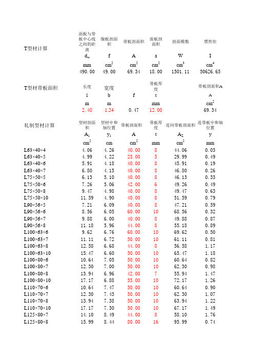
型材剖面模数计算
- 格式:xls
- 大小:46.00 KB
- 文档页数:2


剖面模数计算剖面模数是指材料或构件在剖面方向上的刚度。
它是用来计算剖面弯曲刚度或剖面截面形状对剖面变形的影响程度的一个参数。
在工程设计中,剖面模数的计算常常涉及到材料力学性质和截面形状等多个因素。
下面将详细介绍剖面模数的计算方法,并给出一些相关参考内容。
一、剖面模数的定义:剖面模数是指材料或构件在剖面方向上的刚度,表示材料或构件抵抗剖面方向上变形的能力。
剖面模数的单位通常是mm^3。
二、剖面模数的计算方法:1.矩形截面:对于矩形截面,剖面模数的计算公式为:W = bh^2/6其中,W表示剖面模数,b和h分别表示矩形截面的宽度和高度。
2.圆形截面:对于圆形截面,剖面模数的计算公式为:W = πd^3/32其中,W表示剖面模数,d表示圆形截面的直径。
3.其他复杂截面:对于其他复杂的截面形状,可以通过将其分割成多个简单的几何体来计算剖面模数,然后将结果进行相加。
例如,可以将T 形截面分割成矩形和两个L形截面,然后计算每个部分的剖面模数,并将它们相加得到总的剖面模数。
三、相关参考内容:1.《结构计算手册》(程季男著):该书对剖面模数的计算方法作了详细的介绍,涵盖了各种常见截面形状的剖面模数计算公式,同时还对剖面模数的应用进行了讲解。
2.《结构力学与结构设计》(刘妙德、吴少军著):该书对剖面模数的计算方法进行了深入的研究,重点介绍了复杂截面形状的剖面模数计算方法,并给出了实际应用案例。
3.《钢结构设计手册》(沈大成、杨智、吕玉奇著):该手册对剖面模数的计算方法进行了详细的介绍,包括各种常见钢结构截面形状的剖面模数计算公式,并对剖面模数的应用进行了实例分析。
4.《建筑结构》(许春明、王道生主编):该书对剖面模数的计算方法进行了全面的介绍,包括各种常见剖面形状的剖面模数计算公式以及计算步骤,对于各类材料的剖面模数计算均有详细说明。
以上是关于剖面模数计算的相关参考内容,读者可以根据实际需求选择参考书籍或文献来进行学习和研究。

Allowable stress to ABS MODU 2001, part 3, charpter 2, section 1, item 3.3F=Fy/F.S., whereFy = 235 N/mm2 , or 34 ksiF.S. = 1.67 for axial or bending stress2.50 for shear stressHence, F = 140.7 N/mm2 , or 20.4 ksi for axial or bending stress94.0 N/mm2 , or 13.6 ksi for shear stress1. Bulkhead1.1 Wind pressure p = f V k2.c h.c s N/m2wheref = 0.611Vk = 100 knots = 51.44 m/sc s = 1.0c h = 1.1hence p = 1778.4 N/m2or 37.13 lbf/ft21.2 Bulkhead platingPlate panel maximum size (mm)4070 by 690Plate thickness, t (mm)8Bulkhead load to wind pressure p = 1778.4 N/m2or 37.13 lbf/ft2Stress due to lateral perpendicular load:σ = kpb2/t2 wherek = 0.741 for panel size ratio of 5.9 (4070/690)p =37.13lbf/ft2, or0.26 lbf/in2b =690 mmt =8mmHenceσ =1421 lbf/in2, or 1.42ksi OK3Shear stress at support,τ = RF max/A web = 4.49N/mm2, or0.7ksi OK2. Bottom2.1. bottom platingPlate panel maximum size (mm)2650 by 830Plate thickness, t (mm)8Deck load to MODU 2001, w920 kgf/m2, or 188 lbf/ft2Stress due to lateral perpendicular load:σ = kwb2/t2 wherek = 0.718 for panel size ratio of 3.19 (2650/830)w =188lbf/ft2, or 1.31 lbf/in2b =830mmt =8mmHenceσ =10090 lbf/in2, or10.1ksi OK33. APV' lower Supporting StructureAs per contract specification 2.22G, foundations for equipment shall be designed for combined staticand dynamic load of 1.5g vertical and 0.5g horizontal for roll and pitch.According to HYDRALIFT Drawing: T2820-D1157-G0040 APV's arrangement,per WORKING APV' average weight: 2750kg,add 10% variables: 3025kg is to be used in following calculation.3.1 check supporting plate panelThe supporting plate panel, which is supported at four sides, is considered conservatively as plate beam supported at two longer edges.Plate panel concentrated load maximum size (mm)1420 by 760Plate thickness, t (mm) =25.5Deck load to MODU 2001, w =920kgf/m2, or 188 lbf/ft2Max moment due to deck load q: M q =qL/8 =925N.mwhere L =0.76mMax reaction force due to deck loa R q=qL/2=4870NLoad Case 1 (LC1): Heave at 1.5gForce due to static and dynamic load:P = ma,wherem=3025kga=14.7m/s2 (1.5g)P=44467.5NHence,Q=2P = 88935NM1max=Ql1l2/L=16605N.mwhere L=0.76ml1=0.33ml2=0.43mR1max=Ql2/L=50318NForce due to pitch:P=ma,wherem=3025kga= 4.9m/s2 (0.5g)P pitch=14822.5NHence,Q2=2.755*P/5.76 = 7090NThe force acts on plate as a longitudinal tension, as illustrated in sketchLC3: Roll at 0.5g to starboardForce due to roll:P=ma,wherem=3025kga= 4.9m/s2 (0.5g)P=14822.5NHence,Q2=2.755*P/5.76 = 7090NThe force acts on plate as a transverse tension, as illustrated in sketchLC4: Heave at 1.5g, pitch at 0.5g to forward and roll at 0.5g to starboard (LC1+LC2+LC3)moment:BM max=M1max + Mq =17530N.mshear:RF max=R1max + Rq =55188Nlongitudinal tension:TF x =14179Ntransverse tension:TF y =14179Nplate beam modulus:SM=bt2/6 =154cm3where b =142cmt = 2.55cmplate beam area:A1 =bt =362cm2A2 =at =194cm2where a =76cmBending stress,σ = BM max/SM =113.91N/mm2, or16.5ksi OK Shear stress,τ = RF max/A1 = 1.52N/mm2, or0.2ksi OK Longitudinal tension stress:σx = TF x/A2 =0.73N/mm2, or0.1ksi OK Transverse tension stress:σy = TF y/A1 =0.39N/mm2, or0.1ksi OK3.2 Check supporting structurewhere L= 1.42mBM max = (q1+q2)L2/8 =1774kgf.mRFmax = (q1+q2)L/2 = 4997kgf3Bending stress ,σ = BM max/SM = 6.21N/mm2, or0.9ksi OK Shear stress ,τ = RF max/A1 = 6.81N/mm2, or 1.0ksi OKb. Beam A2-B2Similar to beam A1-B1, check beam A2-B2 stress is OK.R B2 =4964kgfc. Beam A3-B3Similar to beam A1-B1, check beam A3-B3 stress is OK.R B3 =2697kgfd. Beam A4-B4Similar to beam A1-B1, check beam A4-B4 stress is OK.R B4 =2482kgfe. Beam A5-B5Similar to beam A1-B1, check beam A5-B5 stress is OK.R B5 =4964kgff. Beam A6-B6Similar to beam A1-B1, check beam A6-B6 stress is OK.R B6 =4964kgfg. Beam A7-B7Similar to beam A1-B1, check beam A7-B7 stress is OK.R B7 =4964kgfh. Beam A8-B8Similar to beam A1-B1, check beam A8-B8 stress is OK.R B8 =4964kgfi. Beam A9-B9Similar to beam A1-B1, check beam A4-B4 stress is OK.R B9 =2482kgfj. Beam C1-D1Similar to beam A1-B1, check beam C1-D1 stress is OK.R C1 =4989kgfR D1 =4989kgfk. Beam C2-D2Similar to beam A1-B1, check beam C2-D2 stress is OK.R C2 =4957kgfR D2 =4957kgfl. Beam C3-D3Similar to beam A1-B1, check beam C2-D2 stress is OK.R C3 =2690kgfR D3 =2690kgf3.2.2 Check transverse girdersMax moment due to force R B1: M B1 = 0.76*1.985*R B1/2.745 =2746kgf.mMax moment due to force R B2: M B2 = 1.42*1.325*R B2/2.745 =3402kgf.mMax moment due to force R B3: M B3 = 2.08*0.665*R B3/2.745 =1359kgf.m Combined moment: BM max =6163kgf.mReaction force: R E1 = 1.985*R B1/2.745 + 1.325*R B2/2.745 + 0.665*R B3/2.745 =6663kgf Reaction force: R F1a = 0.76*R B1/2.745 + 1.42*R B2/2.745 + 2.08*R B3/2.745 =5995kgf hence,RF max =6663kgfBending stress ,σ = BM max/SM =24.00N/mm2, or 3.5ksi OK Shear stress ,τ = RF max/A WEB =8.17N/mm2, or 1.2ksi OKn. Beam E2-F2Similar to beam E1-E1, check beam E2-F2 stress is OK.Reaction force: R F2 =5984kgfDistributed load along the beam length due to bulkhead weight, q = 660kgf/mMax moment due to load q: M q =qL2/8 =622kgf.mMax moment due to force R D1: M D1 = 0.76*1.985*R D1/2.745 =2742kgf.mMax moment due to force R D2: M D2 = 1.42*1.325*R D2/2.745 =3398kgf.mMax moment due to force R D3: M D3 = 2.08*0.665*R D3/2.745 =1355kgf.mCombined moment: BM max =6774kgf.mReaction force: R E3 =7558kgfReaction force: R F3a =6890kgfhence,RF max =7558kgfBending stress ,σ = BM max/SM =26.38N/mm2, or 3.8ksi OK Shear stress ,τ = RF max/A WEB =9.27N/mm2, or 1.3ksi OKDeck load to MODU 2001, w = 920kgf/m2 or 188 lbf/ft2Distributed load along the beam length, q = 0.165*w =151.8kgf/mMax moment due to load q: M q =q*1.4452*(1+1.3/2.745)2/8 =86kgf.mMax moment due to force R B4: M B4 = 1.445*1.3*R B4/2.745 =1699kgf.mMax moment due to force R B5: M B5 = 2.105*0.64*R B5/2.745 =3402kgf.mCombined moment: BM max =4259kgf.mReaction force: R F1b =2424kgfReaction force: R =5146kgfthk(cm)width(cm)sectionarea(cm2)ctr.dist. toplt top(cm)d(cm)I0 (cm4)mom. ofinert.(cm4)SM(cm3)top flg 2.5516.542.075 1.27522.844135.0web1808042.5542666.748997.3btm flg0.816.513.282.950.732077.6 Combined135.27533.7125210.02520 Bending stress ,σ = BM max/SM =16.58N/mm2, or 2.4ksi OK Shear stress ,τ = RF max/A WEB = 6.31N/mm2, or0.9ksi OKDeck load to MODU 2001, w = 920kgf/m2 or 188 lbf/ft2Distributed load along the beam length, q1 = 0.165*w =151.8kgf/mDistributed load along the beam length due to bulkhead weight, q2 = 660kgf/m BM max = (q1+q2)L2/8 =765kgf.mRFmax = (q1+q2)L/2 = 1114kgfHence,R =1114kgfBending stress ,σ = BM max/SM = 2.98N/mm2, or0.4ksi OK Shear stress ,τ = RF max/A WEB = 1.37N/mm2, or0.2ksi OKr. Beam E5-F5Similar to beam F3-E5, check beam E5-F5 stress is OK.Reaction force: R E5b =1185kgfR F5 =1185kgfDeck load to MODU 2001, w = 920kgf/m2 or 188 lbf/ft2Distributed load along the beam length, q = 0.165*w =151.8kgf/mMax moment due to load q: M q =q*0.832*(1+2.66/3.49)2/8 =41kgf.mMax moment due to force R B6: M B6 = 0.68*2.81*R B6/3.49 =2718kgf.mMax moment due to force R B7: M B7 = 1.34*2.15*R B7/3.49 =4098kgf.mMax moment due to force R B8: M B8 = 2.0*1.49*R B8/3.49 =4239kgf.mMax moment due to force R B9: M B9 = 2.66*0.83*R B9/3.49 =1570kgf.mCombined moment: BM max =9829kgf.mReaction force: R E4b =9779kgfBending stress ,σ = BM max/SM =38.27N/mm2, or 5.6ksi OK Shear stress ,τ = RF max/A WEB =11.99N/mm2, or 1.7ksi OK3.2.3 Check longitudinal girdersDeck load to MODU 2001, w = 920kgf/m2 or 188 lbf/ft2Distributed load along the beam length, q = 0.3*w =276kgf/mMax moment due to load q: M q =q*3.5882/2 =1777kgf.mMax moment due to force R F1a +R F1b: M F1 = 0.938*(R F1a+R F1b) =7897kgf.mMax moment due to force R F2: M F2 = 2.193*R F2 =13123kgf.mMax moment due to force R F3a +R F3b: M F1 = 3.588*(R F3a+R F3b) =29041kgf.mCombined moment: BM max =51838kgf.mReaction force: R G1 = q*3.588 + RF1a + RF1b + RF2 + RF3a + RF3b=23397kgfBending stress ,σ = BM max/SM =167.46N/mm2, or24.3ksi OK Shear stress , 1.2τ = RF max/A WEB =65.58N/mm2, or9.5ksi OKDeck load to MODU 2001, w = 920kgf/m2 or 188 lbf/ft2Distributed load along the beam length, q1 = 0.3*w =276kgf/mLoad as Heave at 1.5gForce due to static and dynamic load:P = ma,wherem=3025kga=14.7m/s2 (1.5g)P=44468NHence,q2=2P/L = 6384kgf/mwhere L= 1.42mMax moment due to load q1: M q1 =q1*4.072/2 =2286kgf.mMax moment due to load q2: M q2 =q2*1.422/2 =6437kgf.mMax moment due to force R E4a +R E4b: M E4 = 1.42*(R E4a+R E4b) =21194kgf.mMax moment due to force R E5a +R E5b: M E4 = 4.07*(R E5a+R E5b) =9357kgf.mCombined moment: BM max =39273kgf.mReaction force: R G2 = q1*4.07 +q2*1.42 + R E4a + R E4b + R E5a + R E5b=27413kgf hence,RF =27413kgfBending stress ,σ = BM max/SM =65.74N/mm2, or9.5ksi OK Shear stress ,τ = RF max/A WEB =26.89N/mm2, or 3.9ksi OKv. Beam G3-F5Deck load to MODU 2001, w = 920kgf/m or 188 lbf/ft2Distributed load along the beam length, q1 = 0.165*w =151.8kgf/mDistributed load along the beam length due to bulkhead weight, q2 = 660kgf/m Max moment due to load q1: M q1 =q1*4.072/2 =1257kgf.mMax moment due to load q2: M q2 =q2*4.072/2 =5466kgf.mMax moment due to force R F4: M F4 = 1.42*R F4 =10964kgf.mMax moment due to force R F5: M F5 = 4.07*R F5 =4823kgf.mCombined moment: BM max =22510kgf.mBending stress ,σ = BM max/SM =62.18N/mm2, or9.0ksi OK Shear stress ,τ = RF max/A WEB =11.26N/mm2, or 1.6ksi OK4. APV' Upper Supporting Structure3.1 :P pitch =14822.5NQ1pitch =7733N Load due to a APV's Roll at 0.5g to starboard has calculated as 3.1 :P roll =14822.5NQ1roll =7733N 4.1 Check APV' end box mounting structure on forward transverse bulkhead4.1.1 Check stiffener' flange subjected to tensionAs per "Yield Line Analysis of Bolted Hanging Connections", AISC, Engineering Journal, Vol.14, No.3 1977, For hanger rods, the allowable working load is the smaller of following :P1 = F y t b2(2r)1/2(1+a/b)/LFP2 = F y t b2[r(1+a/b)]1/2/LFwhere F y=235N/mm2t b=13mmr= (F y-F b)/F y =0.401F b=140.7N/mm2a=50mmb=35.5mmLF = 1.7P1 =50388NP2 =22959Nhence,the allowable total force carried by flange[ P ]=22959Nmaximal load forced on stiffener L100x75x13 is P max = 1.5Q1roll = 11600 N < [ P ]OK!4.1.2 Check stiffener subjected to compressionR max =8522N9thk(cm)plt width/sect dep(cm)sectionarea(cm2)ctr.dist. toplt top(cm)d(cm)I0 (cm4)mom. ofinert.(cm4)SM(cm3)att plt0.85644.80.4 2.493.9section-7.515.46 5.9794.6359.7Combined60.26 1.8453.6704.3in3 Bending stress ,σ = BM max/SM =23.83N/mm2, or 3.5ksi OKR max=R F =8738Nthk(cm)plt width/sect dep(cm)sectionarea(cm2)ctr.dist. toplt top(cm)d(cm)I0 (cm4)mom. ofinert.(cm4)SM(cm3)att plt 1.2519.2240.625 3.1196.0section-7.521.06 6.6994.6314.4Combined45.06 3.5510.3965.9in3Bending stress ,σ = BM max/SM =22.61N/mm2, or 3.3ksi OK Shear stress ,τ = RF max/A1 = 4.15N/mm2, or0.6ksi OKC. Check beam L-MR max =11934Nthk(cm)width(cm)sectionarea(cm2)ctr.dist. toplt top(cm)d(cm)I0 (cm4)mom. ofinert.(cm4)SM(cm3)top flg00000.00.0web0.9 2.5 2.25 1.25 1.2 4.8btm flg0.97.5 6.75 2.950.5 1.7Combined9 2.5 6.530.2in3 Bending stress ,σ = BM max/SM =4145.20N/mm2, or601.6ksi OK Shear stress ,τ = RF max/A1 =53.04N/mm2, or7.7ksi OK4.2 Check APV' end box mounting structure on inboard longitudinal bulkheadAs per "Yield Line Analysis of Bolted Hanging Connections", AISC, Engineering Journal, Vol.14, No.3, 1977, For hanger rods, the allowable working load is the smaller of following :P1 = F y t b2(2r)1/2(1+a/b)/LFP2 = F y t b2[r(1+a/b)]1/2/LFwhere F y=235N/mm2t b=19mmr= (F y-F b)/F y =0.401F b=140.7N/mm2a=50mmb=35.5mmLF = 1.7hence,P1 =107634NP2 =49042Nhence,the allowable total force carried by flange[ P ]=49042Nmaximal concentrated load forced on girder T 811x12.5w P max = 3Q2roll = 23199 N < [ P ]OK!4.2.2 Check longitudinal girder' web stability under compression when roll to starboardAs per "Manual of STEEL CONSTRUCTION Allowable Stress Design", AISC,Slenderness ratio Kl/r =450> 200where K =2l =811mmr = 3.61mmAnd C c =(2*3.142E/F y)1/2 =130where E =200000MpaF y =235N/mm2here,Kl/r >C chence,the allowable stress F a = 12*3.142E/(23*(Kl/r)2 = 5.08N/mm2Compression total load forced on Girder' web section Q =12*Q2roll92796N web section area A=19625mm2RF max =92796Nthk(cm)width(cm)sectionarea(cm2)ctr.dist. toplt top(cm)d(cm)I0 (cm4)mom. ofinert.(cm4)SM(cm3)top flg 2.5547.3120.615 1.27565.474578.2web 1.2581.1101.37543.155563.784757.5btm flg 1.911.521.8584.6 6.674705.9Combined243.8426.1234041.73939240.4in3 Bending stress ,σ = BM max/SM =17.91N/mm2, or 2.6ksi OK Shear stress ,τ = RF max/A web =9.15N/mm2, or 1.3ksi OK4.3 Check supporting APV' end box mounting structure on TF-12 transverse bulkheadBending stress ,σ = BM max/SM =72.79N/mm2, or10.6ksi OK Shear stress ,τ = RF max/A web =17.26N/mm2, or 2.5ksi OKthk(cm)width(cm)sectionarea(cm2)ctr.dist. toplt top(cm)d(cm)I0 (cm4)mom. ofinert.(cm4)SM(cm3)top flg 1.310130.65 1.8871.8web 1.3 6.28.06 4.425.8184.0btm flg 1.957.5109.258.4532.948.7web 1.2581013.453.3262.1top flg 1.25121518.025 2.01270.1Combined155.318.8302636.726916.4in3Bending stress ,σ = BM max/SM =74.44N/mm2, or10.8ksi OK Shear stress ,τ = RF max/A web =17.26N/mm2, or 2.5ksi OK。

型材剖面模数计算要计算型材剖面的模数,首先需要了解型材的截面形状。
常见的型材包括角钢、圆钢、槽钢、工字钢等,每种型材的截面形状都有所不同。
这些型材的截面形状可以通过几何测量或CAD软件进行测量和绘制。
一般来说,计算型材剖面模数可以通过以下步骤进行:1.测量型材的截面尺寸:使用尺子或卡尺等工具测量型材的截面尺寸,并记录下来。
比如,对于角钢的剖面,可以测量上下边缘的高度和左右边缘的宽度。
2.计算型材的截面面积:根据测量得到的尺寸,可以计算出型材的截面面积。
对于角钢的剖面,可以将上下边缘的高度乘以左右边缘的宽度,得到截面的面积。
3.计算型材的惯性矩:惯性矩是衡量型材在受力时抵抗形变的能力。
计算型材的惯性矩需要使用型材的截面尺寸来进行计算。
惯性矩的计算公式根据型材的截面形状和坐标系的选择有所不同。
对于简单的截面形状,比如矩形、圆形等,可以使用经典的惯性矩计算公式进行计算。
对于复杂的截面形状,可以使用CAD软件进行建模,并通过软件提供的计算工具进行计算。
4.计算型材的模数:型材的模数可以通过将型材的惯性矩除以型材的最远离中性轴的距离得到。
模数的计算结果就是型材在剖面上的抗弯刚度。
模数的大小可以反映型材的强度和刚度。
模数越大,说明型材的强度和刚度越大,能够承受更大的外力而不产生较大的形变。
在实际工程应用中,可以根据型材的截面尺寸和模数来选择合适的型材进行设计。
对于需要承受较大外力的结构,应选择截面积大、模数大的型材,以提高结构的强度和刚度。
对于受力相对较小的部位,可以选择截面积小、模数小的型材,以减小结构的重量和成本。
Allowable stress to ABS MODU 2001, part 3, charpter 2, section 1, item 3.3F=Fy/F.S., whereFy = 235 N/mm2 , or 34 ksiF.S. = 1.67 for axial or bending stress2.50 for shear stressHence, F = 140.7 N/mm2 , or 20.4 ksi for axial or bending stress94.0 N/mm2 , or 13.6 ksi for shear stress1. Bulkhead1.1 Wind pressure p = f V k2.c h.c s N/m2wheref = 0.611Vk = 100 knots = 51.44 m/sc s = 1.0c h = 1.1hence p = 1778.4 N/m2or 37.13 lbf/ft21.2 Bulkhead platingPlate panel maximum size (mm)4070 by 690Plate thickness, t (mm)8Bulkhead load to wind pressure p = 1778.4 N/m2or 37.13 lbf/ft2Stress due to lateral perpendicular load:σ = kpb2/t2 wherek = 0.741 for panel size ratio of 5.9 (4070/690)p =37.13lbf/ft2, or0.26 lbf/in2b =690 mmt =8mmHenceσ =1421 lbf/in2, or 1.42ksi OK3Shear stress at support,τ = RF max/A web = 4.49N/mm2, or0.7ksi OK2. Bottom2.1. bottom platingPlate panel maximum size (mm)2650 by 830Plate thickness, t (mm)8Deck load to MODU 2001, w920 kgf/m2, or 188 lbf/ft2Stress due to lateral perpendicular load:σ = kwb2/t2 wherek = 0.718 for panel size ratio of 3.19 (2650/830)w =188lbf/ft2, or 1.31 lbf/in2b =830mmt =8mmHenceσ =10090 lbf/in2, or10.1ksi OK33. APV' lower Supporting StructureAs per contract specification 2.22G, foundations for equipment shall be designed for combined staticand dynamic load of 1.5g vertical and 0.5g horizontal for roll and pitch.According to HYDRALIFT Drawing: T2820-D1157-G0040 APV's arrangement,per WORKING APV' average weight: 2750kg,add 10% variables: 3025kg is to be used in following calculation.3.1 check supporting plate panelThe supporting plate panel, which is supported at four sides, is considered conservatively as plate beam supported at two longer edges.Plate panel concentrated load maximum size (mm)1420 by 760Plate thickness, t (mm) =25.5Deck load to MODU 2001, w =920kgf/m2, or 188 lbf/ft2Max moment due to deck load q: M q =qL/8 =925N.mwhere L =0.76mMax reaction force due to deck loa R q=qL/2=4870NLoad Case 1 (LC1): Heave at 1.5gForce due to static and dynamic load:P = ma,wherem=3025kga=14.7m/s2 (1.5g)P=44467.5NHence,Q=2P = 88935NM1max=Ql1l2/L=16605N.mwhere L=0.76ml1=0.33ml2=0.43mR1max=Ql2/L=50318NForce due to pitch:P=ma,wherem=3025kga= 4.9m/s2 (0.5g)P pitch=14822.5NHence,Q2=2.755*P/5.76 = 7090NThe force acts on plate as a longitudinal tension, as illustrated in sketchLC3: Roll at 0.5g to starboardForce due to roll:P=ma,wherem=3025kga= 4.9m/s2 (0.5g)P=14822.5NHence,Q2=2.755*P/5.76 = 7090NThe force acts on plate as a transverse tension, as illustrated in sketchLC4: Heave at 1.5g, pitch at 0.5g to forward and roll at 0.5g to starboard (LC1+LC2+LC3)moment:BM max=M1max + Mq =17530N.mshear:RF max=R1max + Rq =55188Nlongitudinal tension:TF x =14179Ntransverse tension:TF y =14179Nplate beam modulus:SM=bt2/6 =154cm3where b =142cmt = 2.55cmplate beam area:A1 =bt =362cm2A2 =at =194cm2where a =76cmBending stress,σ = BM max/SM =113.91N/mm2, or16.5ksi OK Shear stress,τ = RF max/A1 = 1.52N/mm2, or0.2ksi OK Longitudinal tension stress:σx = TF x/A2 =0.73N/mm2, or0.1ksi OK Transverse tension stress:σy = TF y/A1 =0.39N/mm2, or0.1ksi OK3.2 Check supporting structurewhere L= 1.42mBM max = (q1+q2)L2/8 =1774kgf.mRFmax = (q1+q2)L/2 = 4997kgf3Bending stress ,σ = BM max/SM = 6.21N/mm2, or0.9ksi OK Shear stress ,τ = RF max/A1 = 6.81N/mm2, or 1.0ksi OKb. Beam A2-B2Similar to beam A1-B1, check beam A2-B2 stress is OK.R B2 =4964kgfc. Beam A3-B3Similar to beam A1-B1, check beam A3-B3 stress is OK.R B3 =2697kgfd. Beam A4-B4Similar to beam A1-B1, check beam A4-B4 stress is OK.R B4 =2482kgfe. Beam A5-B5Similar to beam A1-B1, check beam A5-B5 stress is OK.R B5 =4964kgff. Beam A6-B6Similar to beam A1-B1, check beam A6-B6 stress is OK.R B6 =4964kgfg. Beam A7-B7Similar to beam A1-B1, check beam A7-B7 stress is OK.R B7 =4964kgfh. Beam A8-B8Similar to beam A1-B1, check beam A8-B8 stress is OK.R B8 =4964kgfi. Beam A9-B9Similar to beam A1-B1, check beam A4-B4 stress is OK.R B9 =2482kgfj. Beam C1-D1Similar to beam A1-B1, check beam C1-D1 stress is OK.R C1 =4989kgfR D1 =4989kgfk. Beam C2-D2Similar to beam A1-B1, check beam C2-D2 stress is OK.R C2 =4957kgfR D2 =4957kgfl. Beam C3-D3Similar to beam A1-B1, check beam C2-D2 stress is OK.R C3 =2690kgfR D3 =2690kgf3.2.2 Check transverse girdersMax moment due to force R B1: M B1 = 0.76*1.985*R B1/2.745 =2746kgf.mMax moment due to force R B2: M B2 = 1.42*1.325*R B2/2.745 =3402kgf.mMax moment due to force R B3: M B3 = 2.08*0.665*R B3/2.745 =1359kgf.m Combined moment: BM max =6163kgf.mReaction force: R E1 = 1.985*R B1/2.745 + 1.325*R B2/2.745 + 0.665*R B3/2.745 =6663kgf Reaction force: R F1a = 0.76*R B1/2.745 + 1.42*R B2/2.745 + 2.08*R B3/2.745 =5995kgf hence,RF max =6663kgfBending stress ,σ = BM max/SM =24.00N/mm2, or 3.5ksi OK Shear stress ,τ = RF max/A WEB =8.17N/mm2, or 1.2ksi OKn. Beam E2-F2Similar to beam E1-E1, check beam E2-F2 stress is OK.Reaction force: R F2 =5984kgfDistributed load along the beam length due to bulkhead weight, q = 660kgf/mMax moment due to load q: M q =qL2/8 =622kgf.mMax moment due to force R D1: M D1 = 0.76*1.985*R D1/2.745 =2742kgf.mMax moment due to force R D2: M D2 = 1.42*1.325*R D2/2.745 =3398kgf.mMax moment due to force R D3: M D3 = 2.08*0.665*R D3/2.745 =1355kgf.mCombined moment: BM max =6774kgf.mReaction force: R E3 =7558kgfReaction force: R F3a =6890kgfhence,RF max =7558kgfBending stress ,σ = BM max/SM =26.38N/mm2, or 3.8ksi OK Shear stress ,τ = RF max/A WEB =9.27N/mm2, or 1.3ksi OKDeck load to MODU 2001, w = 920kgf/m2 or 188 lbf/ft2Distributed load along the beam length, q = 0.165*w =151.8kgf/mMax moment due to load q: M q =q*1.4452*(1+1.3/2.745)2/8 =86kgf.mMax moment due to force R B4: M B4 = 1.445*1.3*R B4/2.745 =1699kgf.mMax moment due to force R B5: M B5 = 2.105*0.64*R B5/2.745 =3402kgf.mCombined moment: BM max =4259kgf.mReaction force: R F1b =2424kgfReaction force: R =5146kgfthk(cm)width(cm)sectionarea(cm2)ctr.dist. toplt top(cm)d(cm)I0 (cm4)mom. ofinert.(cm4)SM(cm3)top flg 2.5516.542.075 1.27522.844135.0web1808042.5542666.748997.3btm flg0.816.513.282.950.732077.6 Combined135.27533.7125210.02520 Bending stress ,σ = BM max/SM =16.58N/mm2, or 2.4ksi OK Shear stress ,τ = RF max/A WEB = 6.31N/mm2, or0.9ksi OKDeck load to MODU 2001, w = 920kgf/m2 or 188 lbf/ft2Distributed load along the beam length, q1 = 0.165*w =151.8kgf/mDistributed load along the beam length due to bulkhead weight, q2 = 660kgf/m BM max = (q1+q2)L2/8 =765kgf.mRFmax = (q1+q2)L/2 = 1114kgfHence,R =1114kgfBending stress ,σ = BM max/SM = 2.98N/mm2, or0.4ksi OK Shear stress ,τ = RF max/A WEB = 1.37N/mm2, or0.2ksi OKr. Beam E5-F5Similar to beam F3-E5, check beam E5-F5 stress is OK.Reaction force: R E5b =1185kgfR F5 =1185kgfDeck load to MODU 2001, w = 920kgf/m2 or 188 lbf/ft2Distributed load along the beam length, q = 0.165*w =151.8kgf/mMax moment due to load q: M q =q*0.832*(1+2.66/3.49)2/8 =41kgf.mMax moment due to force R B6: M B6 = 0.68*2.81*R B6/3.49 =2718kgf.mMax moment due to force R B7: M B7 = 1.34*2.15*R B7/3.49 =4098kgf.mMax moment due to force R B8: M B8 = 2.0*1.49*R B8/3.49 =4239kgf.mMax moment due to force R B9: M B9 = 2.66*0.83*R B9/3.49 =1570kgf.mCombined moment: BM max =9829kgf.mReaction force: R E4b =9779kgfBending stress ,σ = BM max/SM =38.27N/mm2, or 5.6ksi OK Shear stress ,τ = RF max/A WEB =11.99N/mm2, or 1.7ksi OK3.2.3 Check longitudinal girdersDeck load to MODU 2001, w = 920kgf/m2 or 188 lbf/ft2Distributed load along the beam length, q = 0.3*w =276kgf/mMax moment due to load q: M q =q*3.5882/2 =1777kgf.mMax moment due to force R F1a +R F1b: M F1 = 0.938*(R F1a+R F1b) =7897kgf.mMax moment due to force R F2: M F2 = 2.193*R F2 =13123kgf.mMax moment due to force R F3a +R F3b: M F1 = 3.588*(R F3a+R F3b) =29041kgf.mCombined moment: BM max =51838kgf.mReaction force: R G1 = q*3.588 + RF1a + RF1b + RF2 + RF3a + RF3b=23397kgfBending stress ,σ = BM max/SM =167.46N/mm2, or24.3ksi OK Shear stress , 1.2τ = RF max/A WEB =65.58N/mm2, or9.5ksi OKDeck load to MODU 2001, w = 920kgf/m2 or 188 lbf/ft2Distributed load along the beam length, q1 = 0.3*w =276kgf/mLoad as Heave at 1.5gForce due to static and dynamic load:P = ma,wherem=3025kga=14.7m/s2 (1.5g)P=44468NHence,q2=2P/L = 6384kgf/mwhere L= 1.42mMax moment due to load q1: M q1 =q1*4.072/2 =2286kgf.mMax moment due to load q2: M q2 =q2*1.422/2 =6437kgf.mMax moment due to force R E4a +R E4b: M E4 = 1.42*(R E4a+R E4b) =21194kgf.mMax moment due to force R E5a +R E5b: M E4 = 4.07*(R E5a+R E5b) =9357kgf.mCombined moment: BM max =39273kgf.mReaction force: R G2 = q1*4.07 +q2*1.42 + R E4a + R E4b + R E5a + R E5b=27413kgf hence,RF =27413kgfBending stress ,σ = BM max/SM =65.74N/mm2, or9.5ksi OK Shear stress ,τ = RF max/A WEB =26.89N/mm2, or 3.9ksi OKv. Beam G3-F5Deck load to MODU 2001, w = 920kgf/m or 188 lbf/ft2Distributed load along the beam length, q1 = 0.165*w =151.8kgf/mDistributed load along the beam length due to bulkhead weight, q2 = 660kgf/m Max moment due to load q1: M q1 =q1*4.072/2 =1257kgf.mMax moment due to load q2: M q2 =q2*4.072/2 =5466kgf.mMax moment due to force R F4: M F4 = 1.42*R F4 =10964kgf.mMax moment due to force R F5: M F5 = 4.07*R F5 =4823kgf.mCombined moment: BM max =22510kgf.mBending stress ,σ = BM max/SM =62.18N/mm2, or9.0ksi OK Shear stress ,τ = RF max/A WEB =11.26N/mm2, or 1.6ksi OK4. APV' Upper Supporting Structure3.1 :P pitch =14822.5NQ1pitch =7733N Load due to a APV's Roll at 0.5g to starboard has calculated as 3.1 :P roll =14822.5NQ1roll =7733N 4.1 Check APV' end box mounting structure on forward transverse bulkhead4.1.1 Check stiffener' flange subjected to tensionAs per "Yield Line Analysis of Bolted Hanging Connections", AISC, Engineering Journal, Vol.14, No.3 1977, For hanger rods, the allowable working load is the smaller of following :P1 = F y t b2(2r)1/2(1+a/b)/LFP2 = F y t b2[r(1+a/b)]1/2/LFwhere F y=235N/mm2t b=13mmr= (F y-F b)/F y =0.401F b=140.7N/mm2a=50mmb=35.5mmLF = 1.7P1 =50388NP2 =22959Nhence,the allowable total force carried by flange[ P ]=22959Nmaximal load forced on stiffener L100x75x13 is P max = 1.5Q1roll = 11600 N < [ P ]OK!4.1.2 Check stiffener subjected to compressionR max =8522N9thk(cm)plt width/sect dep(cm)sectionarea(cm2)ctr.dist. toplt top(cm)d(cm)I0 (cm4)mom. ofinert.(cm4)SM(cm3)att plt0.85644.80.4 2.493.9section-7.515.46 5.9794.6359.7Combined60.26 1.8453.6704.3in3 Bending stress ,σ = BM max/SM =23.83N/mm2, or 3.5ksi OKR max=R F =8738Nthk(cm)plt width/sect dep(cm)sectionarea(cm2)ctr.dist. toplt top(cm)d(cm)I0 (cm4)mom. ofinert.(cm4)SM(cm3)att plt 1.2519.2240.625 3.1196.0section-7.521.06 6.6994.6314.4Combined45.06 3.5510.3965.9in3Bending stress ,σ = BM max/SM =22.61N/mm2, or 3.3ksi OK Shear stress ,τ = RF max/A1 = 4.15N/mm2, or0.6ksi OKC. Check beam L-MR max =11934Nthk(cm)width(cm)sectionarea(cm2)ctr.dist. toplt top(cm)d(cm)I0 (cm4)mom. ofinert.(cm4)SM(cm3)top flg00000.00.0web0.9 2.5 2.25 1.25 1.2 4.8btm flg0.97.5 6.75 2.950.5 1.7Combined9 2.5 6.530.2in3 Bending stress ,σ = BM max/SM =4145.20N/mm2, or601.6ksi OK Shear stress ,τ = RF max/A1 =53.04N/mm2, or7.7ksi OK4.2 Check APV' end box mounting structure on inboard longitudinal bulkheadAs per "Yield Line Analysis of Bolted Hanging Connections", AISC, Engineering Journal, Vol.14, No.3, 1977, For hanger rods, the allowable working load is the smaller of following :P1 = F y t b2(2r)1/2(1+a/b)/LFP2 = F y t b2[r(1+a/b)]1/2/LFwhere F y=235N/mm2t b=19mmr= (F y-F b)/F y =0.401F b=140.7N/mm2a=50mmb=35.5mmLF = 1.7hence,P1 =107634NP2 =49042Nhence,the allowable total force carried by flange[ P ]=49042Nmaximal concentrated load forced on girder T 811x12.5w P max = 3Q2roll = 23199 N < [ P ]OK!4.2.2 Check longitudinal girder' web stability under compression when roll to starboardAs per "Manual of STEEL CONSTRUCTION Allowable Stress Design", AISC,Slenderness ratio Kl/r =450> 200where K =2l =811mmr = 3.61mmAnd C c =(2*3.142E/F y)1/2 =130where E =200000MpaF y =235N/mm2here,Kl/r >C chence,the allowable stress F a = 12*3.142E/(23*(Kl/r)2 = 5.08N/mm2Compression total load forced on Girder' web section Q =12*Q2roll92796N web section area A=19625mm2RF max =92796Nthk(cm)width(cm)sectionarea(cm2)ctr.dist. toplt top(cm)d(cm)I0 (cm4)mom. ofinert.(cm4)SM(cm3)top flg 2.5547.3120.615 1.27565.474578.2web 1.2581.1101.37543.155563.784757.5btm flg 1.911.521.8584.6 6.674705.9Combined243.8426.1234041.73939240.4in3 Bending stress ,σ = BM max/SM =17.91N/mm2, or 2.6ksi OK Shear stress ,τ = RF max/A web =9.15N/mm2, or 1.3ksi OK4.3 Check supporting APV' end box mounting structure on TF-12 transverse bulkheadBending stress ,σ = BM max/SM =72.79N/mm2, or10.6ksi OK Shear stress ,τ = RF max/A web =17.26N/mm2, or 2.5ksi OKthk(cm)width(cm)sectionarea(cm2)ctr.dist. toplt top(cm)d(cm)I0 (cm4)mom. ofinert.(cm4)SM(cm3)top flg 1.310130.65 1.8871.8web 1.3 6.28.06 4.425.8184.0btm flg 1.957.5109.258.4532.948.7web 1.2581013.453.3262.1top flg 1.25121518.025 2.01270.1Combined155.318.8302636.726916.4in3Bending stress ,σ = BM max/SM =74.44N/mm2, or10.8ksi OK Shear stress ,τ = RF max/A web =17.26N/mm2, or 2.5ksi OK。