太阳能交通灯
- 格式:docx
- 大小:25.94 KB
- 文档页数:6
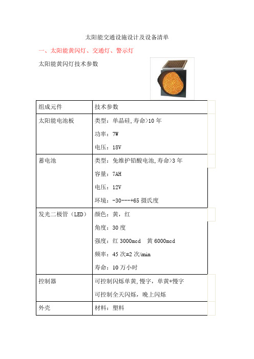
太阳能交通设施设计及设备清单一、太阳能黄闪灯、交通灯、警示灯太阳能黄闪灯技术参数二、太阳能指示牌,交通标志牌,LED牌,标志牌三、有源道钉隧道诱导灯隧道诱导标可见距离大于500M 光源单面6个LED 尺寸100x105x19mm(mm)光源颜色白黄红绿等太阳功率12(W)电池12V10AH发光频率2 类型LED道钉材质耐高温ABS 型号TP-2008控制器供电系统:普通交流电转变为24V/5A控制器尺寸:200x125x75mm控制器防护等级:IP65变压器尺寸:75x125x125mm变压器防护等级:IP20控制器包括变压器总重量:1.6kg输出电压:24V DC安装:在现有配电箱,单独的保护箱内,或者太阳能集中供电控制功能:常亮/同步闪烁/追踪闪烁(高级功能选用)四、太阳能移动红绿灯太阳能移动信号灯交通信号灯随着科技的发展,道路交通管理日渐复杂。
为了满足道路交通安全管理,涉及到方便,节能,环保,因而我们开发、生产出了新一代移动式LED智能交通信号灯,可以充分展现你的管理才能,让你更加轻松、便捷的管理道路交通。
产品功能:1、嵌入式中央控制系统,工作更加稳定可靠。
2、全中文液晶显示,调试更位方便,醒目。
3、全天候室外移动机箱,立杆装有升降功能装置。
4、整部机器采用模块化设计, 便于维修和功能扩充。
5、22路、6组灯独立控制输出,典型工作电流10A。
6、可扩展RS-232、RS-485接口与上位机通讯。
7、可在线调整、检查和设置。
8、控制主机可交流与直流通用。
9、控制主面板在工作过程中可处于待机状态,这样使你更加节省电量。
10、采用进口太阳能电池板(18V/100W)和蓄电池(12V/150AH)阴雨天可持续工作10天。
11、产品具备充电,过流过压低压保护。
7、有多时段多相位,供平常日和节假日分别工作。
8、有10个工作模式,可在任意时段多次调用。
9、每个可编程菜单可编程99步,每步定时为1~255秒。

一体化太阳能移动式交通信号灯安装使用说明书 整机图片注明:为了能够安全标准的使用本公司的一体化太阳能移动交通信号灯,再安装和使用前请先认真的看本说明书,谢谢!一、太阳能移动信号灯结构:(如图1)由本公司自主研发设计的一体化太阳能移动式交通信号灯主要由四大部分组成:1.太阳能发电光伏板;(图1-1)2.红绿灯一体化灯箱;(图1-2)3.信号灯可升降主杆;(图1-3)4.信号灯可移动底座;(图1-4)二、产品简介:产品设计机构新颖,安装方便简单,交通信号指示灯和信号控制系统均符合GB14887-2003和GA47-2002道路交通信号控制机标准设计,产品具有抗干扰能力,自主通过太阳能电池光伏板发电向蓄电池充电的性能;控制系统经过软件来控制蓄电池的输出电压和检测蓄电池是否欠压,如果蓄电池欠压,则信号灯将不工作,信号控制系统的主面板商的欠压指示灯将指示欠压,(注明:整套信号灯安装调试好后,为了节约蓄电池电能,请按控制系统面板上的 显示按钮键,熄灭控制面板上的 LED和LCD,如果需要调试时,请再次按显示按钮键,LED和LCD将自动显示)在蓄电池电压满足不了现状时,请用本公司配置的10A交流充电器给蓄电池充电,当电压进入保护时,10A 交流充电器一般充电时间在4到8个小时既可,为了产品的使用寿命安全,请不要再不清楚的 情况先知道摘除产品各部位的 部件或自行接线等。
(控制系统面板如图2)三、产品结构部分介绍:A、信号灯可移动式底座:移动式灯箱的结构由:手拉杆、户外防水箱、蓄电池、信号控制系统、Ø100刹车轮组成;B、信号灯可升降式主杆:信号灯可升降式主杆由:上法兰盘、下法兰盘、上固定杆、下固定杆、钢丝绳子、齿轮和手柄组成;C、红绿灯一体化灯箱:红绿灯一体化灯箱由:四面防水灯箱、亚克力透镜、LED灯板、驱动板灯、遮阳板组成D、太阳能发电光伏板:太阳能发电光伏板由:太阳能电池板、安装支架组成;四:移动信号灯安装流程:(如图3)步一:先把一体化灯箱底部的两根线电缆先穿入可升降式主要杆上法兰盘,然后从下法兰盘把电线拉出来,其次用配套好的4个M14×40的螺丝先固定还一体话灯箱和升降杆;(注:连接时,小心不要压断电缆线):步二:安装可移动底座和步一之间的连接(连接是先将两个电缆线伸进可移动灯箱里边,注意不要压电缆线,升降手柄最好放在手拉杆面)然后用4个配套好的M14×40的螺丝把固定好底座;步三:安装一体化灯箱上的12片遮阳板;步四:然后安装太阳能电池,太阳能电池安装支架留有两个Ø12通控,安装时只需要把配置好的两个M12的螺丝固定在一体化灯箱上即可,安装好后请将太阳能板的电源线插到一体化灯箱顶部的航空接头,然后固定好(这里值得注意的是,正常使用时太阳能电池板必须朝南方向;根据实际情况调整好太阳能板的上下角度)步五:步一到步四安装好后,最后把移动底座的上盖和侧面的小盖的螺丝打开,从控制面板的出线口内穿入一根小铁丝,然后把两根电缆线拉上来,然后按航空接头的针控4位对4位对接,5位对5位对接就可以了。

太阳能黄闪灯、爆闪灯太阳能黄闪灯和爆闪灯都是一种使用太阳能作为能源的警示灯装置,常用于道路交通安全、船舶导航等场景。
下面是对两种灯具的详细描述:1. 太阳能黄闪灯:太阳能黄闪灯是一种通过太阳能电池板转换太阳能为电能,并储存在电池中的装置。
它通常由以下几个部分组成:- 太阳能电池板:将太阳能转换为电能的关键部件,通常安装在灯具的顶部,以最大程度地吸收阳光。
- 电池:用于储存太阳能转换而来的电能,以便在夜间或阴天时继续供电。
- LED灯:黄闪灯通常采用高亮度的黄色LED灯,具有低能耗和长寿命的特点。
- 控制器:用于控制灯具的闪烁频率和模式,通常根据道路交通规则进行设置。
- 外壳和支架:用于保护和支持灯具的外部结构,通常采用耐候性强的材料,如铝合金或塑料。
太阳能黄闪灯的工作原理是,在白天太阳能电池板吸收阳光并将其转换为电能,同时充电电池。
在晚上或阴天,电池会供电给LED灯,使其闪烁发光。
闪烁频率和模式可以根据实际需要进行调整,以提醒过往车辆或行人注意安全。
2. 爆闪灯:爆闪灯是一种通过太阳能或其他电源供电的高亮度警示灯。
它通常由以下几个部分组成:- 光源:爆闪灯通常采用高亮度的LED灯或气体放电管作为光源,具有强烈的亮度和可见性。
- 电源:可以是太阳能电池板、电池或外部电源,用于供电给灯具。
- 控制器:用于控制灯具的闪烁频率和模式,通常具有多种闪烁模式可供选择。
- 外壳和支架:用于保护和支持灯具的外部结构,通常采用耐候性强的材料,如铝合金或塑料。
爆闪灯的工作原理是,在接通电源后,控制器会控制光源以特定的频率和模式闪烁发光。
爆闪灯通常具有高亮度和闪烁频率较高的特点,以提高其可见性和警示效果。
根据不同的应用场景和需求,可以选择不同颜色的灯光,如黄色、红色或蓝色。
总之,太阳能黄闪灯和爆闪灯都是利用太阳能或其他电源供电的警示灯装置,用于提醒和警示过往车辆或行人注意安全。
具体的设计和工作原理会根据实际需求和应用场景进行调整和优化。

太阳能移动式红绿灯控制器12V两相位16路(SC-06)使用说明书一、产品介绍SC-06B太阳能移动式红绿灯控制器是针对于中小路口、道路变动、施工断电等情况,便于移动,不用拉电力线就可以快速用于现场的专用交通红绿灯控制器。
控制器支持手持式无线电控制及电脑连机功能设定。
使现场操做更加快速简单。
SC-06B太阳能移动式红绿灯控制器采用Microchip的MCU做中央控制,由软件完成所有控制动作,使控制器具有更高的准确性和更高的稳定性。
控制器拥有16路全独立过载保护,蓄电池充放电管理及完善的系统保护措施。
二、基本应用1、电池接入:将12V蓄电池接入到控制此标示处。
+为正极。
-为负极。
2、太阳能电池接入:将18V太阳能电池接入到控制此标示处。
+为正极。
-为负极。
3、市电接入(可以不接):如果在阳光不充足地区使用时可以接入市电,建议选用12V 3A 至5A 的充电变压器 (使用者需另购)接于控制此标示处。
+为正极。
-为负极。
(此器件非产品标配,使用者需另购)4、天线接入:如果需要使用遥控器时请接引天线。
天线可以用23CM 有绝源层的铜线自制,也可采用315MHz 专用天线。
接于控制此标示处。
(此器件出厂时已连接于此接线位)5、红绿接入:SC-06B 控制器采用共正极(正阳极)接线方式。
两边各一个公共正极。
其余为各个灯的负极。
如果在阳光不充足N 表示北行 W 表示西行 NR 北行红灯 WR 西行红灯 NY 北行黄灯 WY 西行黄灯 NG 北直行绿灯 WG 西直行绿灯 NG2 北左行绿灯 WG2 西左行绿灯 S 表示南行 E 表示东行 SR 南行红灯 ER 东行红灯 SY 南行黄灯 EY 东行黄灯 SG 南直行绿灯 EG 东直行绿灯 SG2 南左行绿灯 EG2 东左行绿灯至此已可以正常工作,如果要使用到更多功能请继续以下步骤进行。
6、电池温度传感器:如果在温度变化较大的地区使用,建议连接电池温度传感器。
(使用者需另购)接于控制器此标示处。

太阳能交通警示灯操作规程
《太阳能交通警示灯操作规程》
一、范围
本规程规定了太阳能交通警示灯的操作程序,适用于所有使用太阳能交通警示灯的地方。
二、操作人员
1. 操作人员应具备相关的操作证书和经验,对太阳能交通警示灯的使用和维护有一定的了解。
2. 操作人员应定期接受相关操作培训,了解太阳能交通警示灯的操作规程和注意事项。
三、操作程序
1. 在使用太阳能交通警示灯之前,操作人员应进行全面的检查,确保设备完好,无损坏和故障。
2. 操作人员按照设备说明书的要求进行操作,确保正确打开和关闭太阳能交通警示灯。
3. 在太阳能交通警示灯出现故障或异常情况时,操作人员应立即停止使用,并进行必要的维修和检查,确保设备安全可靠。
四、注意事项
1. 在使用太阳能交通警示灯时,操作人员应严格按照操作规程进行操作,避免私自调整或改动设备。
2. 在操作过程中,应及时清理太阳能交通警示灯上的灰尘和污垢,保持设备表面清洁。
3. 在遇到恶劣天气情况时,应及时停止使用太阳能交通警示灯,以免影响设备寿命和使用效果。
通过严格执行《太阳能交通警示灯操作规程》,可以有效确保太阳能交通警示灯的正常运行和安全使用,提高道路交通安全水平。

太阳能路灯原理太阳能路灯是一种利用太阳能发电的照明设备,它能在夜间提供光照,为行人和车辆提供安全保障。
太阳能路灯的原理是将太阳能转化为电能,然后通过电能来点亮灯具。
下面将详细介绍太阳能路灯的原理和工作过程。
一、太阳能发电原理太阳能发电是利用光伏效应将太阳能转化为电能的过程。
光伏效应是指当光线照射到半导体材料上时,会激发出电子,从而产生电流。
太阳能电池板就是利用光伏效应来将太阳能转化为电能的装置。
太阳能电池板由多个光伏电池组成,每一个光伏电池都是由两层硅材料构成的。
当光线照射到光伏电池上时,上层硅材料中的电子会被激发出来,形成电流。
这个电流经过导线传输到电池板的输出端,就可以供给其他设备使用。
二、太阳能路灯的工作原理太阳能路灯的工作原理是将太阳能转化为电能,然后通过电能来点亮灯具。
太阳能路灯普通由太阳能电池板、电池、控制器和灯具组成。
当太阳升起时,太阳能电池板就会开始工作。
太阳能电池板将太阳能转化为电能,并将电能存储到电池中。
电池的作用是将白日储存的电能保存起来,以便夜间使用。
在夜偶尔光线不足的情况下,控制器会自动感知到环境的变化,并打开电池中的电路,将电能供给灯具。
灯具中的LED灯泡会通过电能点亮,为周围提供照明。
太阳能路灯的控制器还具备自动开关的功能。
当光线足够亮时,控制器会自动关闭电池的电路,住手供电给灯具,以节省能源。
而当光线不足时,控制器会自动打开电池的电路,继续供电给灯具。
三、太阳能路灯的优势太阳能路灯具有许多优势,使其成为一种受欢迎的照明设备。
首先,太阳能路灯不需要外部电源,它利用太阳能发电,不消耗传统能源,因此具有环保的特点。
它不会产生二氧化碳等有害气体,对环境没有污染。
其次,太阳能路灯具有独立性和可挪移性。
它不需要接入电网,可以独立工作,适合于各种地理环境。
同时,它也可以根据需要进行挪移和安装,非常灵便。
此外,太阳能路灯的维护成本较低。
一旦安装完毕,它们基本上不需要额外的维护费用。
太阳能LED路灯主要技术要求太阳能LED路灯是一种利用太阳能发电,在夜间提供照明的道路照明设备。
它具有节能环保、可再生能源利用和智能控制等优势,因此在城市道路、乡村道路、学校、工厂和公园等各种场所得到广泛应用。
太阳能LED路灯的主要技术要求包括光源、能源供应、控制系统和外壳等方面,下面将详细介绍。
一、光源技术要求1.亮度要求:太阳能LED路灯需要具备足够的亮度,确保道路在夜间能够清晰可见,提供安全的照明环境。
2.色温要求:太阳能LED路灯的色温要求适宜,能够提供舒适的照明效果,不会造成眩光和视觉疲劳。
3.色彩还原指数要求:太阳能LED路灯的色彩还原指数要高,能够真实还原物体的颜色,方便人们辨认物体。
4.光照均匀性要求:太阳能LED路灯的光照均匀性要好,避免出现明暗不均的状况,确保道路上没有盲点。
5.可调光要求:太阳能LED路灯应具备可调光的功能,根据路况和需求调整照明亮度,实现节能控制。
二、能源供应技术要求1.太阳能板要求:太阳能LED路灯的太阳能板需要具备高效转换阳光能量的能力,提供足够的电能供应。
2.蓄电池要求:太阳能LED路灯的蓄电池需要具备较大的储电容量,能够在夜间维持LED灯的正常工作。
3.充放电控制技术要求:太阳能LED路灯需要配备充放电控制系统,能够实现对蓄电池的合理充放电管理,延长蓄电池的使用寿命。
三、控制系统技术要求1.自动光控技术:太阳能LED路灯的控制系统应具备自动感应光控功能,根据环境光照自动调整灯光亮度。
2.时序控制技术:太阳能LED路灯的控制系统需要具备时序控制功能,能够根据时间设定,实现灯光的开关和调光控制。
3.故障报警技术:太阳能LED路灯的控制系统应具备故障自动报警功能,能够及时发现和处理设备故障,确保路灯正常工作。
四、外壳技术要求1.防水性能:太阳能LED路灯的外壳需要具备良好的防水性能,能够在恶劣的天气条件下正常工作。
2.防尘性能:太阳能LED路灯的外壳需要具备防尘能力,避免灯光受到灰尘等物质的影响。
太阳能黄闪灯说明书太阳能黄闪灯说明书太阳能黄闪灯是以太阳能为能源的一种交通信号灯,它对来往于路口的车辆起警示作用,以减少交通事故的发生。
本产品具有不需外接电源,不需布线,安装简单方便,无污染等特点,特别适合于学校门口、铁路道口、位于公路上的村口以及偏远的、交通流量大、用电不方便而又易发生交通事故的路口。
本产品选用的免维护铅酸蓄电池,在使用时无需加水,无酸液泄露,内阻低,大小电流放电均可;具有耐震动性好,抗过充电、过放电能力强、自放电小、寿命长等特点。
本产品带有过充、放电保护电路,最大限度保护蓄电池。
拨码开关打在开的位置为开,反之为关。
技术参数:1.电池组件:10W单晶硅;2.蓄电池:12V7a电池;3.太阳能电池的峰值电压:≥16.5V4.太阳能峰值功率:10W7.额定电压:12V8.光源类型:LED光源;亮度黄色6000-8000mcd9.LED数量:9010. 尺寸:375*375*12011. 灯盘工作电流:180mha12. 二极管的视角:20°13.闪烁频率:120次±2次/min;14.连续阴天时的工作时间:5天15.可视距离:≥1000米(空旷)16.使用温度:-35℃至+65℃;安装说明1.打开黄闪灯门盖,将电池固定到支架里,然后将等箱内的红色线接到电池正极,黑色线接到电池负极,接好后打开开关,检查灯是否工作正常,盖上门盖。
2.将太阳能板固定在黄闪灯顶部螺丝上,适当调节太阳能板方向,使充电效果最佳。
3.打开太阳能板背面集线盒,将爆闪灯的电线连接到太阳能板闪,其中红色为正级,黑色为负极,将其与太阳能板的正负极对应。
4.将连接好太阳能板的黄闪灯安装到已经柱子上,然后将黄闪灯底部管子上的固定螺丝拧紧。
太阳能交通灯的开发作者:滕俊杰来源:《职业·中旬》2011年第08期太阳能交通灯系统,即在阳光充足的情况下,通过控制电路将太阳能转化为电能储存在蓄电池中;同时,通过放电控制将蓄电池中的电送出来,通过逆变器,将交流电变为直流电送给交通灯,使交通灯工作,到光线弱的时候充电停止,放电仍在进行;蓄电池中存储的电,通过控制器继续供交通灯使用。
一、太阳能板的选择太阳能光伏发电系统是通过太阳能电池吸收阳光,将太阳的光能直接变成电能输出。
但是,单个太阳能电池往往因为输出电压太低,输出电流不合适,晶体硅太阳能电池本身又比较脆,不能独立抵御外界恶劣条件,因而在实际使用中,需要把单体太阳能电池进行串、并联,并加以封装,接出外连电线,成为可以独立作为光伏电源使用的太阳能电池组件(Solar Module 或PV Module,也称光伏组件)。
具有外部封装及内部连接、能单独提供直流电输出的最小不可分割的太阳能电池组合装置,叫太阳能电池组件。
两个或两个以上的太阳能电池组件,在机械和电器上按一定方式组装在一起,并且有固定的支撑结构而构成的直流发电单元,叫太阳能电池阵列。
简而言之,多个单体太阳能电池互联封装后成为组件,多个太阳能电池组件互联拼装后成为阵列。
像任何半导体元器件一样,即使是同一条生产线,用同一种工艺制造出的单体太阳能电池或太阳能电池组件,其电气特性也会多少有一点差异。
二、贮能蓄电池在太阳能供电系统中,太阳能的大小,受季节、天气及每日时间的影响很大。
当太阳能充足时,发电量会大于负荷的需求;当太阳能不充足或缺少时,发电量会小于负荷需求,甚至不能提供电能。
因此,太阳能供电系统必须有储能设备。
通常采用蓄电池储能,当太阳能较充足时,多余的电能被储存在蓄电池中;当太阳能不足时,蓄电池参与放电,而当太阳能短缺时,则完全由蓄电池单独供电,即蓄电池在太阳能供电系统中起着储能与供电的双重作用。
三、充放电控制电路1.充电控制电路该电路为恒流充电电路,当充电电压达到要求值时,能自动切断充电电流。
鉴于很多客户给我们反馈太阳能黄闪灯的安装方法,很多新手不知道该如何去安装,湘旭交安下面来给大家介绍下太阳能黄闪灯的安装方法和应用。
太阳能黄闪灯的安装方法及应用
太阳能黄闪灯已经习惯性叫太阳能黄闪灯,也可以叫太阳能警示灯,它无须外界电源,是不具备外接电源的交通路口理想的交通警示标志,这种太阳能黄闪灯功耗低,寿命长,运行成本低,被誉为绿色环保产品。
一。
【太阳能黄闪灯的安装方法】
1、出厂时已配安装配件。
2、安装时灯箱安装方向以发光方向正对来车方向
100m外的车道中心,并以地面垂直安装。
3、安装挡尘罩时用不锈钢螺丝把遮阳罩拧紧固定在灯箱上盖螺丝孔位上。
4、安装时钻好立柱与灯箱连接孔位(灯箱支架两内孔孔中心距离是50mm两外孔中心距离是190mm)然后用不锈钢螺丝把灯箱后支架拧紧固定。
5、安装太阳能板时,先用“1字型”支架上的两孔对应太阳能板上的两个孔位在把“V字型”支架放在“1字型”支架上,用不锈钢螺丝拧紧固定在一起,太阳能板连接支架固定好以后安放在灯箱支架上,用不锈钢螺拧紧固定。
6、安装高度由客户自定,立柱需方自备。
二.太阳能黄闪灯的应用范围
1、道路需要警示标志路短,以及匝道路口;
2、危险施工道路;
3、道路弯道及高架桥路段诱导标示;
应于大家的要求,已经把黄闪灯安装的方法技巧详细的做了阐述了,希望对大家有帮助。
A NEW LOGICAL CONTROL MODEL OF TRAFFIC LIGHTSSUN Xian-bo1,2, LIN Wei2, and ZHANG Nan-lun21Information Engineering School of Hubei Institute for Nationalities, Hubei, China, 4450002Automation School of Wuhan University of Technology, Hubei, China, 430070 Abstract: Based on Pan-Boolean algebra with an illustration of crossroads in the urban trunk roads, a new logical control model of the traffic light is designed in this paper. It breaks down the conventional pattern of fixed time distribution, realizes a flexible control and takes into account the combinations of various traffic lanes. Characterized by simple presentation and convenient operation, it can be clearly shown after the simulation that the model is preferable to the conventional pattern of fixed time distribution in promoting the efficiency of traveling vehicles. Since it can make the vehicles travel more efficiently, it may be employed in the near future. Key Words: traffic light, logical control model, Pan-Boolean Algebra, simulation1 IntroductionIt is of practical significance to enhance the traffic efficiency at the intersectionsto alleviate the traffic jam. Nowadays, the traffic lights are designed with certain shift cycles according to the supposed number of vehicles. However, the fixed timing has lots of demerits and greatly reduces the traffic efficiency. To improve the urban road traveling capability, reduce the delay caused by intersections, the ITS (Intelligent Transportation System) has been studied. The signal lights at intersections usually have fixed timing control, the induction-type control and the adaptive control. Since the traffic flow is complex, dynamic and random, the former two control models are not entirely satisfactory in practice. The adaptive control system represented by SCOOT(Yang Xianfu,2003) can adjust the signal timing according to the actual traffic, and hence it works well, but it needs to be more accurate. Since it is easily affected, it lacks a perfect effect on the complicated traffic situation in China. Therefore, a new logical control model of the traffic light is designed in thispaper based on Pan-Boolean algebra(Zhang Nanlun,2005) with the traveling time from all directions and enhances the flexibility and practicality of the traffic timing.2 Pan-Boolean AlgebraPan-Boolean algebra is a logical model based on the relation between input and output. The guiding principle of this algebra is that such marks as 1 2 3 x , x , x …are the1794various variables in the multi-condition system and then the total of all possible conditions of any variable i x can be referred to as its corresponding “condition number”, which can be expressed as i n (i=1,2,...). ji x (i=1,2,…; j=1,2,… i n ) isc alled the “condition variable”, that is, the jth condition corresponding to i x . Namely,when the jth condition appears, 1 is taken as its value while when there is no jth condition, 0 is taken as its value. In this multi-condition system, every variable i xin a certain case can and merely can be in one state of all i n . It means it has tosimultaneously satisfy both of the conditions:(1) 1 2 ... n 1i i i x + x + + x = ; (2)ji x ·ki x =0 (1≤j<k≤i n )Except these two conditions, all those laws including associative law, the commutative law, the distributive law and 0-1 law are similarly established as in the Boolean algebra, so it is called as Pan-Boolean algebra. The difference between logical control, traditional control and fuzzy control(CHOU Chih-Hsun,2002) is as follows: traditional control theory rests on differential equation to have an automatic control; whereas, both fuzzy control and logical control rest on the concept control. Fuzzy control is different from logical control in that the former is based on the fuzzy set theory of Charder IA and its relevant operation principle while the latter is built on the regularities Pan-Boolean algebra observes. The make-up law of fuzzy set does not work while that of Pan-Boolean algebra does work. Moreover, non-operation has diverse definitions in the two systems. It differs from fuzzy control with modification on the ground that one employs mathematics analysis formula to represent the rule of control and the response to output while the other adopts Pan-Boolean indication, which conforms to the human thinking.3 Description of a Typical Transportation SystemThis paper mainly touches on the intersections of main roads in cities. As is illustrated in Figure 1, all the traffic lanes can be divided into 12 according to such 4 directions as A, B, C and D. There are 3 traffic lanes in each direction involvingleft-turn lane, straight lane and right-turn lane. For example, A1, B4, C7 and D10 are all left-turn lanes, A2, B5, C8 and D11 are all straight lanes and A3, B6, C9, D12 are right-turn lanes. As far as the traffic regulations and vehicles safety are concerned, only two lanes without any conflict are allowed to be in operation in the same period. Since right-turn vehicles have no impact on vehicles from other directions when they pass the intersection, they are excluded from the control. The traffic flow in consideration holds 4 phases as is shown in Figure 2, which shifts from one to1795another according to the flow. Based on the specific flow of each lane, 3 types are proposed: small capacity (0-3), medium capacity (4-8) and large capacity (9-16). Thus, when the sensors from A1, A2, B4, B5, C7, C8, D10 and D11 check out the exact number of passing vehicles, the traffic lanes will be reduced to one of the above three lanes. For instance, A1 is a lane with small capacity if 2 cars are checked out on it. The maximum is 16, which is set by experience and regulated by traffic departments. It is certain that one or several more categories can be added, but there is no theoretically substantial difference except that more presentations and more designs are needed.Figure 1. Distribution Map at IntersectionFigure 2. Illustration of Phases4 Design of Control ModelOn the basis of Pan-Boolean algebra, a corresponding model is to be established, where the signals of flow from the sensors on A1, A2, B4, B5, C7, C8, D10 and D11 are combined and input. Accordingly, the traffic lights will be varied due to different traffic flows and lanes will be shifted as Figure 2 illustrates, which ensures two lanes are always in operation and also optimizes the road resources. Meanwhile, the waiting time for pass must be above a minimum (10s is supposed here) to ensure pedestrians and non-motor vehicles have enough time and below a maximum (80s is supposed here) to ensure vehicles from opposite directions do not wait for too long. The combinations of A2 and C8, B5 and D11, A1 and C7, B4 and D10, as separately input condition variables, are marked respectively as X1 (flow of straight vehicles from east and west), X2 (flow of straight vehicles from north and south), X3 (flow of left-turn vehicles from east and west) and X4 (flow of right-turn vehicles from north and south). The condition values of the variables are respectivelyn1 = 3,3 2 n = ,3 3 n = ,3 4 n = . That is to say, the following will be input systematically as condition variables: 11 x (a small flow of straight vehicles from eastand west),21 x (a medium flow of straight vehicles from east and west),31 x (a large1796flow of straight vehicles from east and west),12 x (a small flow of straight vehiclesfrom north and south),22 x (a medium flow of straight vehicles from north andsouth),32 x (a large flow of straight vehicles from north and south),13 x(a small flowof left-turn vehicles from east and west),23 x (a medium flow of left-turn vehiclesfrom east and west),33 x (a large flow of left-turn vehicles from east and west),14 x(a small flow of left-turn vehicles from north and south),24 x (a medium flow ofleft-turn vehicles from north and south)and 34 x (a large flow of left-turn vehiclesfrom north and south). In addition, this system is made up of 4 output variables: 1 Y (traffic lights for passing straight from east and west),2 Y (traffic lights for passing straight from north and south),3 Y (traffic lights for left-turn from east and west),4 Y (traffic lights for left-turn from north and south). The state number of the fouroutput variables are respectively n1 = 2 ,n2 = 2,n3 = 2,n4 = 2 . That is, all the output variables include: 11 y (red light for passing straight from east and west),21 y(green light for passing straight from east and west),12 y (red light for passingstraight from north and south),22 y (green light for passing straight from north andsouth),13 y (red light for left turn from east and west),23 y (green light for left-turnfrom east and west),14 y (red light for left-turn from north and south),24 y (greenlight for left-turn from north and south).Suppose the traffic lights only shift among the above-mentioned 4 phases and inthe same situation straight way is prior to turning left and east - west is prior to north –south. 2 F stands for the output of succession and 12 f (23)2 f represent thedifferent output signals of 23kinds of successions(the outputs of succession vary on different supposals.).Table 1 shows the logical diagram.1797Table 1. The Logical Diagram of Traffic Light Control at the IntersectionA logical diagram of traffic lights control at the intersection is available, but the specific control steps in one succession are not offered. The outputs concern with succession. Take 12 f for example, which involves 4 phases in succession and can beshown as 12 f (1), 12 f (2), 12 f (3), 12 f (4). The whole output is the logical total of 4 phases:12 f =12 f (1)+ 12 f (2)+ 12 f (3)+ 12 f (4)It can be described in details as:12 f (1) =21 y 1y2 1y3 1y4It means “keeping the green light on A2 and C8 on for 10 seconds, the red lighton B5 and D11 on for 10 seconds, the red light for left-turn on A1 and C7 on for 10 seconds, the red light for left-turn on B4 and D10 for 10 seconds.”12 f (2) =1y1 12 y 23 y 14 yIt means “keeping green light for left-turn on A1 and C7 on for 10 seconds, redlight for left-turn on B4 and D10 on for 10 seconds, red light on A2 and C8 on for 10 seconds, red light on B5 and D11 on for 10 seconds”.12 f (3) =1y1 22 y 1y3 1y4It means “keeping green light on B5 and D11 on for 10 seconds, red light on A2and C8 on for 10 seconds, red light for left-turn on A1 and C7 on for 10 seconds, red light for left-turn on B4 and D10 on for 10 seconds”.12 f (4) =1y1 1y2 1y3 2y4It means “keeping green light for left-turn on B4 and D10 on for 10 seconds, red1798light for left-turn on A1 and C7 on for 10 seconds, red light on A2 and C8 on for 10 seconds, red light on B5 and D11 on for 10 seconds”.These are the output succession of 12 f . Other variables from 22 f to 232 f include4 steps similar to it, which will not be introduced here.5 SimulationsTo testify the priority of logical control model, the software MATLAB is employed to simulate the fixed timing and the logical control. Supposing the intersection is as in Figure 1 and the 12 traffic lanes from 4 directions are considered and Supposing the lanes for right-turn are not put under control and only lanes forleft-turn and straight passing are considered, the traffic lights on each lane will be shifted dynamically as is shown in Figure 2. In the random situations, two models of M are used to simulate the process, the result of which is displayed in Figure 3: Figure 3. Simulated Result6 ConclusionsThe new logical control model based on Pan-Boolean algebra here is practicaland easy to handle, which surpasses the conventional model of fixed timing for traffic lights and is suitable for controlling the traffic lights in usual cases. 4 phases are considered because it can prevent the traffic flows from different directions from conflicting with each other. Furthermore, since it conforms to the present traffic rule, it is easy to be publicized and improve the traffic efficiency. As is shown in the simulation, this model is applicable and effective, which is worth developing. ReferencesCHOU Chih-Hsun,TENG Jen-Chao. A fuzzy logic controller for traffic junction signals[J].Information Sciences,2002,143 (1):73-97YANG Xianfu, The adaptive system of traffic lights based on EDA [J], the Journal of Chengdu University (natural science version), 2003,22(3):19~24ZHANG Nanlun, A new control theory [M], Beijing: State Defense Industry Press, 2005, 11799。