帕克液压气动样本
- 格式:pdf
- 大小:768.13 KB
- 文档页数:4
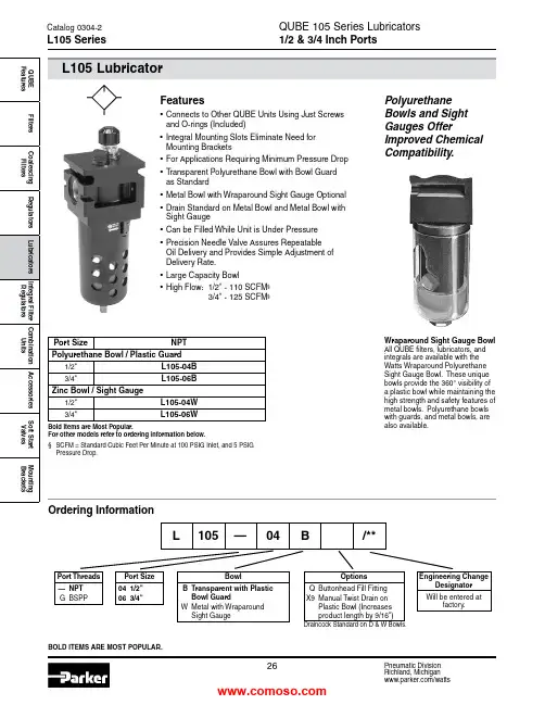
BowlB Transparent with Plastic Bowl GuardW Metal with Wraparound Sight GaugePort Size 04 1/2" 06 3/4"Port Threads — NPT G BSPPL105 —04 B /**QUBE 105 Series Lubricators 1/2 & 3/4 Inch PortsBOLD ITEMS ARE MOST POPULAR.Engineering ChangeDesignator Will be entered atfactory.Features• Connects to Other QUBE Units Using Just Screws and O-rings (Included)• Integral Mounting Slots Eliminate Need for Mounting Brackets• For Applications Requiring Minimum Pressure Drop • T ransparent Polyurethane Bowl with Bowl Guard as Standard• Metal Bowl with Wraparound Sight Gauge Optional • Drain Standard on Metal Bowl and Metal Bowl with Sight Gauge• Can be Filled While Unit is Under Pressure • Precision Needle Valve Assures Repeatable Oil Delivery and Provides Simple Adjustment of Delivery Rate.• Large Capacity Bowl • High Flow: 1/2" - 110 SCFM § 3/4" - 125 SCFM §Wraparound Sight Gauge Bowl All QUBE filters, lubricators, andintegrals are available with the Watts Wraparound Polyurethane Sight Gauge Bowl. These unique bowls provide the 360° visibility of a plastic bowl while maintaining the high strength and safety features of metal bowls. Polyurethane bowls with guards, and metal bowls, are also available.Polyurethane Bowls and Sight Gauges OfferImproved Chemical Compatibility.Ordering InformationPort Size NPT Polyurethane Bowl / Plastic Guard1/2"L105-04B3/4"L105-06B Zinc Bowl / Sight Gauge1/2"L105-04W 3/4"L105-06WBold Items are Most Popular.For other models refer to ordering information below.§ SCFM = Standard Cubic Feet Per Minute at 100 PSIG Inlet, and 5 PSIG Pressure Drop.OptionsQ Buttonhead Fill FittingX9 Manual Twist Drain on Plastic Bowl (Increases product length by 9/16")Catalog 0304-2L105 SeriesDraincock Standard on D & W Bowls.12345P r e s s u r e D r o p -P S I G 4P r e s s u r e D r o p - b a r.1.2.3Primary Pressure - PSIG 1.73.4 5.2 6.910.3Primary Pressure - bar 0Rated Flow - SCFM 20103040605070Flow - dm /s3nP r e s s u r e D r o p - P S I GP r e s s u r e D r o p - b a r.1.2.3Primary Pressure - PSIG 1.73.4 5.2 6.910.3Primary Pressure - barRated Flow - SCFM 20103040605070Flow - dm /s3nQUBE 105 Series LubricatorsInches (mm)* 3/8 and 1/2 inch ports † 3/4 inch portsL105 Lubricator Kits & AccessoriesBowl Kits –Polyurethane (B) ...............................................................BKL105B Zinc (D) (with Drain) .........................................................BKF105D Zinc (W) Wraparound Sight Gauge (with Drain) ..............BKF105W Button Head Fill Fitting (M14 Male Thread) .....................L606C14 Drain Kits –Manual T wist Drain ........................................................SA600Y7-1Oil –1 Gal. .................................................................................F442002 12 Quart Case ...................................................................F4420034 Gallon Case ....................................................................F442005Face Mounting Bracket Kit (See Page 39) ....................SAR105Y57 Repair Kit –Tamper-resistant Sight Dome (All) ......................................RKL100SpecificationsBowl Capacity ...................................................................8.5 Ounce Port Threads ................................................................1/2 & 3/4 Inch Pressure & Temperature Ratings –Polyurethane Bowl .............................0 to 150 PSIG (0 to 10.2 bar)40°F to 125°F (4.4°C to 52°C) Zinc Bowl ...........................................0 to 300 PSIG (0 to 20.4 bar) 40°F to 150°F (4.4°C to 65.6°C)Zinc Bowl w/ Sight Gauge .................0 to 250 PSIG (0 to 17.2 bar) 40°F to 150°F (4.4°C to 65.6°C)Suggested Lubricant ...........................................................F442 Oil Petroleum-based oil of 100 to 200 SUS viscosity at 100°F and ananiline point greater than 200°F(DO NOT USE OILS WITH ADDITIVES, COMPOUNDED OILS CONT AINING SOLVENTS, GRAPHITE, DETERGENTS, OR SYNTHETIC OILS.)Weight –Polyurethane Bowl ........................................ 1.09 lb. (0.5 kg) / Unit 10.7 lb. (4.9 kg) / 8-unit Master Pack Zinc Bowl ...................................................... 1.53 lb. (0.7 kg) / Unit 14.2 lb. (6.4 kg) / 8-unit Master Pack Zinc Bowl W/ Sight Gauge .............................1.71 lb. (0.8 kg) / Unit 15.7 lb. (7.1 kg) / 8-unit Master PackMaterials of ConstructionBody .....................................................................................Aluminum Bowls .............................................................................PolyurethaneMetal (Zinc)Drains .......................................................................................Brass Fill Fitting .................................................................................Brass Seals ..........................................................................................NitrileA*A †B C D E F*F †GL105-B2.69 (68.4)3.03 (77.0) 2.69 (68.4) 3.00 (64.3) 6.03 (153.4) 1.34 (34.1) 2.25 (56.1) 2.55 (64.8)0.81 (20.3)L105-D2.69 (68.4)3.03 (77.0) 2.69 (68.4) 3.00 (64.3) 6.62 (168.2) 1.34 (34.1) 2.25 (56.1) 2.55 (64.8)0.81 (20.3)LF105-W2.69 (68.4)3.03 (77.0) 2.69 (68.4) 3.00 (64.3) 6.90 (175.3) 1.34 (34.1) 2.25 (56.1) 2.55 (64.8)0.81 (20.3)Catalog 0304-2Technical Specifications – L105。

PARKER派克B53424MTF气动电磁阀技术参数讲解说明PARKER派克B53424MTF气动电磁阀技术参数讲解说明HYLIK海历克张涛张经理今天给大家讲讲关于PARKER派克B53424MTF气动电磁阀没有现货的额,需要订货的,订货周期8-10周左右的。
这款B53424MTF气控阀这个型号自带线圈的,客户不需要再单独购买线圈了哦。
下面带给大家是到货实物图以及技术参数讲解等。
“既然人生只是一场体验,那就少不了酸甜苦辣各尝一遍,悲欢离合都经历一次。
夏天,不是季节,是一种内心的状态。
冰激凌,不是冷饮,是一种恰逢其时的快乐。
锅碗瓢盆,不是厨具,是构成生活的一件件乐器。
人生是用来体验的,不是用来演绎美的。
接受自己身上那些灰暗的部分,原谅自己的迟钝和平庸,允许自己出错,允许自己偶尔断电。
无论怎样,不要气馁,更别放弃,请昂首阔步走下去。
唯有历经风雨的洗涤,方可与彩虹不期而遇。
”B系列,一种性能越的工业阀门,尺寸紧凑,流量范围增强。
有电磁先导操作和远程空气先导型号可供选择。
B系列采用Parker久经考验的WCS(磨损补偿密封)系统,保使用寿命长、响应快。
PARKER派克B53424MTF气动电磁阀适用于端环境Viking Xtreme系列阀是用于劣环境工业的管接式阀。
电磁先导控制&气控先导,可选择汇流板和震动线圈。
抗盐雾和抗冲击。
温度从40F到140F;工作压力从真空到232PSIG;接口螺纹尺寸从1/8"到1/2"。
-Viking Xtreme系列Viking Lite系列阀是用于通用工业的管接式阀。
是先导控制、汇流板安装式。
温度范围从14F到122F,工作压力从22到145PSI;接口螺纹尺寸从1/8" 到 3/8"。
派克B53424MTF技术规格:最高运行温度:122°F,59°c低运行温度:14°F,-10°c最大运行压力:10bar ,145 psig 阀门类型:3通,4通位置数量:2位,3位端口数量:5通启动类型:电磁先导控制超控功能:非锁定和锁定手动按钮安装类型:管接,IEM 汇流棒歧管出口数量:10端口尺寸:1/8 1/4 3/8 端口类型:BSPP,NPT最小流速:0.6Cv 最大流速:2.5Cv输入电压:24VDC,120VAC 电气连接:22mm:3针(DIN 43659 B型)符合规格:IP65,RoHs,CE 额定压力:22到145psig ,1.5到10bar最小运行压力:22,43.5 psig 工作温度:-10到+50°c,+14到+122°F介质:空气润滑剂:无需润滑功耗:2.5w 阀体材质:阳极氧化铝密封材质:丁晴橡胶Viking Lite阀是一种坚固的,多功能的管接式阀,结合了高性能和紧凑的安装尺寸,非常适合于一般通用的工业应用。
液压注意 – 用户方责任 错误或不当地选择或使用本样本或有关资料阐述的产品,可能会导致人生伤亡及财产损失! 本样本以及其它由派克汉尼汾公司及其子公司、销售公司与授权分销商所提供的资料,仅供用户专业技术人员在对产品和系统的选型进行深入调查考证时参考。
用户应全面分析自身设备的运行工况、适用的工业标准,并仔细查阅现行的样本,以详细地了解产品及系统的相关信息,通过自己的分析和试验,对产品及系统的独立的最终选择负责,确保能满足自身设备的所有性能、耐用性、维修型、安全性以及预警功能等要求。
对于派克或其子公司或授权分销商而言,应负责按用户提供的技术资料和规范,选择和提供适当的元件或系统,而用户则应负责确定这些技术资料和规范对其设备的所有运行工况和能合理预见的使用工况是否充分和准确。
目录目录页次概述 1 订货代号 2 技术参数 4 变量控制器 5 控制选项 “C”, 压力限定(恒压)变量控制器 5 控制选项 “L”, 负载传感及压力限定变量控制器 6 控制选项 “AM”, 带遥控口的标准型先导式压力限定变量控制器 7 控制选项 “AN”, 带ISO 4401 NG06先导阀安装界面的先导式压力限定变量控制器 8 控制选项 “AE”及“AF”, 带电磁比例调节的先导式压力限定变量控制器 9 控制选项 “AMT”, “ALT”及“LOT”, 带最高压力限定的扭矩限定(恒功率)变量控制器 10 P1性能特性 11典型流量特性 11 典型总效率特性 13 典型轴输入功率特性 15 典型噪声特性 18 典型轴承寿命 20 PD性能特性 22典型流量特性 22 典型总效率特性 24 典型轴输入功率特性 26 典型噪声特性 29 典型轴承寿命 31 安装尺寸 33 P1/PD 018 33 P1/PD 028 36 P1/PD 045 40 P1/PD 060 44 P1/PD 075 49 P1/PD 100 54 P1/PD 140 59 变量控制器安装尺寸 65 可提供的扩展的液压产品 75派克汉尼汾备记派克汉尼汾概述简介, 优点派克汉尼汾简介 • 开式回路用轴向柱塞式变量液压泵 • 中压,连续工作压力280 bar • 高驱动转速型,适用于行走机械; 低噪声型,适用于工业应用 • 静音及高效的控制效能 优点 • 总结构尺寸紧凑 • 低噪声• 流量脉动小,进一步降低噪声• 采用弹性密封,不使用密封垫,从而避免外泄漏的产生• 总效率高,功耗小,减小发热• 采用带无泄漏调节装的简单变量控制器 • 符合SAE 及ISO 标准的安装法兰及油口 • 采用圆锥滚柱轴承,使用寿命长 • 全功率后驱动能力• 后部或侧面油口配置可选• 泄油口的配置对水平安装及驱动轴向上垂直安装均适用• 带有最大及最小排量调节选项 • 具有壳体至吸口单向阀选项,可延长轴封寿命 • 使用、维修方便 脉动容腔技术下列图表所示为侧向油口配置P1/PD 18, 28及45泵采用 “脉动容腔” 技术的效果,脉动容腔可降低泵出口处的压力脉动幅值40-60%,这样,无需增加成本来加装噪声缓冲元件,便可大大降低液压系统的整体噪声,P1系列 PD 系列出口压力p / bar平均压力脉动 / b a rP1 045出口压力脉动2600 rpm 无脉动容腔2600 rpm 带脉动容腔订货代号18 ml, 28 ml, 45ml派克汉尼汾P 类型 01 驱动轴 转向R 5密封材料E 油口配置0 壳体-吸口 单向阀 0 排量调节 018 排量 S 安装法兰 及油口 S 轴封 M 应用范围A 设计系列0 通轴驱动选项 C0控制选项0附加控制选项 00油漆 00修改代号系列 P D * 仅适用于045排量, “S”型安装法兰及油口00 标准型, 无修改M2 按要求修改 代号修改代号 * 适用于028及045排量 ** 仅适用于045排量 代号设计系列 A 现行设计系列5 氟碳橡胶 (FPM) 代号密封材料 A 82-2 SAE A M33x2 M27x2 BSPP 1/4”, 3/8” 101-2 SAE B M42x2 M27x2 BSPP 1/4”, 1/2” 101-2SAE B M48x2M33x2Ø38/25DN51/25BSPP 1/4”, 1/2”B ISO M33x2 M27x2 BSPP 1/4”,3/8”ISO M42x2 M27x2 BSPP 1/4”, 1/2” ISO M48x2M33x2Ø38/25DN51/25BSPP 1/4”, 1/2”代号 018排量 028排量 045排量 安装法兰及油口 安装 法兰 螺纹 油口 辅助 油口 安装 法兰 螺纹 油口 辅助 油口 安装法兰螺纹油口法兰 油口辅助 油口 S 82-2 SAE A SAE 16/12 SAE 4/6 101-2 SAE B SAE 20/12 SAE 4/8 101-2SAE B SAE 24/16Ø38/2561系列SAE 4/10M ISO M33x2 M27x2 M12x1.5 M16x1.5 ISO M42x2 M27x2 M12x1.5 M22x1.5 ISO M48x2M33x2Ø38/25DN51/25M12x1.5M22x1.5代号 018驱动轴 028驱动轴 045驱动轴 01 SAE A 11T 花键SAE B-B 15T 花键 SAE B-B 15T 花键02 SAE 19-1平键Ø0.75” SAE B-B 平键Ø1” SAE B-B 平键Ø1” 08— SAE B 13T 花键 SAE B 13T 花键 04 ISO/DIN 平键, Ø20ISO/DIN 平键, Ø25ISO/DIN 平键, Ø25 06 SAE A 9T 花键— — PD 工业液压用 代号 系列P1 行走机械用 代号 排量 018 18 ml/rev (1.10 in 3/rev) 028 28 ml/rev (1.71 in 3/rev) 045 45 ml/rev (2.75 in 3/rev) 代号 类型 P 开式回路用变量柱塞泵 U*通用 代号应用范围 S 工业液压 (PD) M 行走机械 (P1) R 顺时针 (右转)L 逆时针 (左转)代号 转向 代号 轴封 S 单唇轴封 * 并不具有控制功能,仅在运输时予以防护,详情见第7页的控制说明。
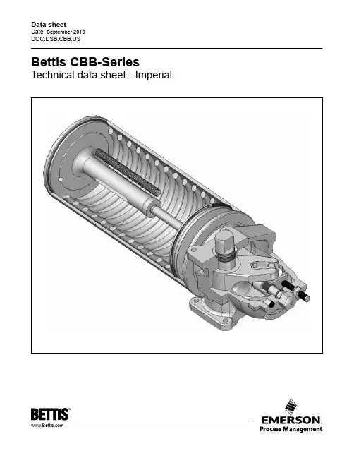
Data sheetDate: September 2010Bettis CBB-Series Technical data sheet - ImperialTorque Ratings – (Pneumatic) All Published Torques are Guaranteed Minimum Values.Actuator Model See Bettis’DefinitionsOperating Pressure (PSIG)405060708090100120Pressure Torque Output Start/Min./End (lb-in)CBB 315Start/End678848101711871356152616952034 Minimum40450560670780891010111213CBB 420Start/End15361921230526893073345738414609 Minimum8711089130715251743196121792614CBB 520Start/End2133266632003733 Minimum1302162819542279CBB 525Start/End29443680441651525888662473618833 Minimum17202150258030093439386942995159CBB725Start/End57577197863610075 11515 Minimum34344292515160096868Double-Acting Actuators CBB-SeriesSpring-Return Actuators CBB-SeriesActuator Model SpringTorqueStart/Min./End(lb-in)Operating Pressure (PSIG)405060708090100120150Pressure Torque Output Start/Min./End (lb-in)CBB315 SR40Start35037553168884410001157131316262095 Min.1511582473364245126006888641128 End2022163775386988591020118115021985CBB315 SR60Start5984386087789481117128716272136 Min.2381532493434365306238081085 End305172342512681851102113601870CBB315 SR80Start7576988841069125416252181 Min.306237328418509689958 End40231249868386912391795CBB315 SR100Start1069876105314061935 Min.405331428621906 End4944216009571493Actuator Model SpringTorqueStart/Min./End(lb-in)Pressure Torque Output Start/Min./End (lb-in)405060708090100120150Operating Pressure (PSIG)Torque Ratings – (Pneumatic) All Published Torques are Guaranteed Minimum Values.Actuator Model SpringTorqueStart/Min./End(lb-in)Operating Pressure (PSIG)405060708090100120150Pressure Torque Output Start/Min./End (lb-in)CBB415 SR40Start68269298112711560185021392429 Min.28428545161477894111051268 End36538770110141328164119552269CBB415 SR60Start10767019791256153318112088 Min.4312644356037709341099 End577294600905121115161822CBB415 SR80Start13451077136216481933 Min.576428602772942 End71151081111131414CBB415 SR100Start165917012007 Min.673542719 End756564861CBB420 SR40Start59184411731501182921572485281334704454 Min.30131750068085910371215139317482282 End4793917091028134616651983230229393894CBB420 SR60Start13201333168520372390274234464503 Min.4814806708601048123516072166 End69156287111791488179724153341CBB420 SR80Start1661146818252182253932534325 Min.655481690891108814802068 End9015028441187152922153243CBB520 SR40Start10041311180523002794328937834278 Min.44550378210561326159618672137 End562677125518342412299035684146CBB520 SR60Start1719138518952405291434243934 Min.7474847941095139016851980 End96650910871665224328213399CBB520 SR80Start257521332658318337084757 Min.10197901111142417342347 End12438931494209526963898CBB520 SR100Start3880253530674132 Min.136185511711773 End171591314912647CBB420 SR100Start22301958232030444130 Min.83664385712641859 End1119674102117162758Actuator Model SpringTorqueStart/Min./End(lb-in)Pressure Torque Output Start/Min./End (lb-in)405060708090100120150Operating Pressure (PSIG)Spring-Return Actuators CBB-Series (cont.)Torque Ratings – (Pneumatic) All Published Torques are Guaranteed Minimum Values.Actuator Model SpringTorqueStart/Min./End(lb-in)Operating Pressure (PSIG)405060708090100120150Pressure Torque Output Start/Min./End (lb-in)CBB525 SR40Start165216192310300136924383507457657147 Min.608638993134516982050240227523452 End9499461637232830193710440150926474CBB525 SR60Start252718492549325039504651535167528854 Min.9836321035142518142198258233484499 End13726941404211428243534424456657795CBB525 SR80Start3038273234324133483362348336 Min.129396613631750213829004042 End1680113018592589331847776965CBB525 SR100Start46203673439258327991 Min.16761369177725813770 End22341696245439706245CBB725 SR40Start3148335447806206763290581048411910 Min.12831306204827883520425249845716 End164119483488502865688108964811189CBB725 SR60Start52493467481761677517886710217 Min.2106123420802897370945115313 End2762128428244364590474448984CBB725 SR80Start7370506463957726905711719 Min.283020182872370645416189 End3330232638855444700310122CBB725 SR100Start94827374878111595 Min.3260247832794828 End4269274842507254Actuator Model SpringTorqueStart/Min./End(lb-in)Pressure Torque Output Start/Min./End (lb-in)405060708090100120150Operating Pressure (PSIG)Spring-Return Actuators CBB-Series (cont.)Notes:♦CBA-SRXXM mechanical handwheel overrides are available on these models. The override adds approximately 2 lbs. (.8 kg) to the weight of thestandard CBA model.▲Maximum volume including cavity required for calculating consumption per stroke.* Maximum Operating Pressure (MOP) is the pressure required to produce the maximum rated torque of the actuator.**Maximum Allowable Working Pressure (MAWP)Standard installation produces clockwise rotationwhen the outboard side of piston is pressurized. Standard installation produces counterclockwise rotation when the inboard side of piston is pressurized.Note: Actuator may be installed opposite of that shown aboveInboardSideSide Performance Data – (Pneumatic)Double-Acting Actuators CBB-SeriesSpring-Return Actuators CBB-SeriesActuator ModelVolumeMaximum Operating Pressure (MOP)*Maximum Allowable Working Pressure(MAWP)**Approximate Weightof Actuator OutboardInboard (Housing)Cu. InchesCubic Cm Cu. InchesCubic Cm PSIG Bar PSIG Bar Lbs.Kg CBB 315 24 393.354 885.0120 8.3200 13.820 9.1CBB 420 53 868.5115 1884.5120 8.3200 13.822 10.0CBB 520 83 1360.1148 2425.370 4.8160 11.028 12.7CBB 525 105 1720.6207 3392.1120 8.3200 13.844 20.0CBB 7252083408.53275358.6805.516011.06831.0Actuator ModelVolumeMaximum OperatingPressure (MOP)*Maximum Allowable Working Pressure(MAWP)**Approximate Weightof Actuator Cu. InchesCubic Cm PSIG Bar PSIG Bar Lbs.Kg ♦CBB 315-SR40SR60SR80SR10054545454885885885885155152 15016410.710.510.311.320020020020013.813.813.813.82223 262510.010.411.811.4♦CBB 415-SR40SR60SR80SR100757575751229122912291229100112117114 6.97.78.17.916016016016011.011.011.011.027293031 12.714.114.114.1♦CBB 420-SR40SR60SR80SR1001151151151151884.51884.51884.51884.5157156161 16610.810.811.011.420020020020013.813.813.813.83739 404116.817.718.118.6♦CBB 520-SR40SR60SR80SR1001481481481482425.32425.32425.32425.31101161201327.68.08.39.116016016016011.011.011.011.0454*******.421.822.224.0♦CBB 525-SR40SR60SR80SR100207207207207339233923392339214615115916310.110.411.011.220020020020013.813.813.813.86265 656728.129.529.530.4♦CBB 725-SR40SR60SR80SR1003273273273275358.65358.65358.65358.6102115 1241247.08.08.68.616016016016011.011.011.011.09798 10410744.044.547.248.5Note: Not Certified dimensional drawings. Such drawings available on request. Contact factory with correct model designation and serial number. All dimensions are expressed in inches.Dimensions – (Pneumatic) In.Double-Acting Actuators CBBXXXActuator Model A B C D E F G H J/K L M N CBB31514.167.38 3.25 1.09 1.88 3.460.940.941/4′′ NPT .313-18 UNC 0.38 2.250CBB42016.438.57 4.25 1.38 2.13 4.37 1.10 1.103/8′′ NPT .375-16 UNC 0.50 3.000CBB52016.468.63 5.38 1.38 2.07 4.37 1.10 1.103/8′′ NPT .375-16 UNC 0.50 3.000CBB52519.229.88 5.38 1.69 2.56 5.00 1.25 1.253/8′′ NPT .500-13 UNC 0.50 3.500CBB72519.4410.247.501.692.535.001.251.253/8′′ NPT.500-13 UNC0.503.500Actuator Model P Q R S T U V W X Y Z AA CBB315.313-18 UNC 1.125 2.91 5.810.75 2.22 5.180.614 0.620 1.03 3.75 1.090.873 0.875CBB420.375-16 UNC 1.500 3.35 6.690.75 2.81 6.250.8640.870 1.03 4.63 1.38 1.1231.125CBB520.375-16 UNC 1.500 3.35 6.690.75 2.81 6.250.8640.870 1.03 4.63 1.38 1.1211.125CBB525.500-13 UNC 1.750 4.388.75 1.12 3.507.58 1.1151.121 1.50 5.75 1.69 1.4981.500CBB725.500-13 UNC1.7504.388.751.123.507.581.1151.1211.505.751.691.4981.500Note: Not Certified dimensional drawings. Such drawings available on request. Contact factory with correct model designation and serial number. All dimensions are expressed in inches.Double-Acting Actuators CBBXXX (cont.)Dimensions – (Pneumatic) In.Note: Not Certified dimensional drawings. Such drawings available on request. Contact factory with correct model designation and serial number. All dimensions are expressed in inches.Spring-Return Actuators CBB XXX-SRXDimensions – (Pneumatic) In.Actuator Model A B C D E F G H J/K L CBB315-SRX 20.1313.66 3.25 1.09 1.88 3.460.940.941/4′′ NPT .313-18 UNC CBB415-SRX 20.2013.71 4.25 1.09 1.88 3.460.940.941/4′′ NPT .313-18 UNC CBB420-SRX 24.5417.07 4.25 1.38 2.13 4.37 1.10 1.103/8′′ NPT .375-16 UNC CBB520-SRX 24.8817.44 5.38 1.38 2.07 4.37 1.10 1.103/8′′ NPT .375-16 UNC CBB525-SRX 28.2118.01 5.38 1.69 2.56 5.00 1.25 1.253/8′′ NPT .500-13 UNC CBB725-SRX28.0918.377.501.692.535.001.251.253/8′′ NPT.500-13 UNCActuator Model M N P Q R S T U V W X Y Z AA CBB315-SRX 0.38 2.250.313-18 UNC 1.125 2.91 5.810.75 2.22 5.180.614 0.620 1.03 3.75 1.090.873 0.875CBB415-SRX 0.38 2.250.313-18 UNC 1.125 2.91 5.810.75 2.22 5.180.614 0.620 1.03 3.75 1.090.8710.875CBB420-SRX 0.50 3.000.375 -16 UNC 1.500 3.35 6.690.75 2.81 6.250.8640.870 1.03 4.63 1.38 1.1231.125CBB520-SRX 0.50 3.000.375 -16 UNC 1.500 3.35 6.690.75 2.81 6.250.8640.870 1.03 4.63 1.38 1.1211.125CBB525-SRX 0.50 3.500.500 -13 UNC 1.750 3.508.75 1.12 3.507.58 1.1151.121 1.50 5.75 1.69 1.4981.500CBB725-SRX0.503.500.500 -13 UNC1.7503.508.751.123.507.581.1151.1211.505.751.691.4981.500Note: Not Certified dimensional drawings. Such drawings available on request. Contact factory with correct model designation and serial number. All dimensions are expressed in inches.Spring-Return Actuators CBB XXX-SRX (cont.)Dimensions – (Pneumatic) In.Note: Not Certified dimensional drawings. Such drawings available on request. Contact factory with correct model designation and serial number. All dimensions are expressed in inches.Double-Acting Actuators CBB XXX-M3(HW)M3(HW) OverrideDimensions – (Pneumatic) In.Actuator Model A B C D E F G H J K CBB315-M3HW 25.2313.01 3.25 6.001/4′′ NPT 1/4′′ NPT 1.8824.2114.37 3.47CBB420-M3HW 30.5815.82 4.258.003/8′′ NPT 3/8′′ NPT 2.1329.1217.37 4.38CBB520-M3HW 30.5815.85 5.258.003/8′′ NPT 3/8′′ NPT 2.0929.0617.37 4.38CBB525-M3HW 36.5218.92 5.2510.003/8′′ NPT 3/8′′ NPT 2.5634.1720.31 5.00CBB725-M3HW36.6519.087.5010.003/8′′ NPT3/8′′ NPT2.5334.1720.315.00Data sheetCBB-SeriesNote: Not Certified dimensional drawings. Such drawings available on request. Contact factory with correct model designation and serial number. All dimensions are expressed in inches.Date: September 2010Sheet No.: CBPI 3.06 RevB Spring-Return Actuators CBB XXX-SRX-M3M3(HW) OverrideCopyright © Emerson Process Management. The information in this document is subject to change without notice.Updated data sheets can be obtained from our website or from your nearest Valve Automation Center. USA: +1 281 727 5300 Europe: +31 74 256 1010 Asia-Pacific: +65 6501 4600Dimensions – (Pneumatic) In.Actuator Model A B C D E F G H CBB315-SR-M3HW 26.6614.43 3.25 6.001/4′′ NPT 9.84 1.88 3.47CBB415-SR-M3HW 26.7414.51 4.25 6.001/4′′ NPT 9.84 1.88 3.47CBB420-SR-M3HW 32.1317.37 4.258.003/8′′ NPT 11.69 2.13 4.38CBB 520-SR-M3HW 32.1617.43 5.388.003/8′′ NPT 11.69 2.09 4.38CBB525-SR-M3HW 36.9319.33 5.3810.003/8′′ NPT 13.86 2.56 5.00CBB725-SR-M3HW36.9819.417.5010.003/8′′ NPT13.862.535.00。
RC系列单作用液压油缸★特有的GR2双重导向环技术能够轻松地吸收偏载,减少磨损,延长油缸寿命。
★外环螺纹、柱塞螺纹和底部安装孔使得定位方便(对多数型号而言)。
★设计为在任何安装位置上使用。
★可拆卸手柄使固定方便(RC-5013,RC-7513和所有95吨型号油缸)。
★高强度合金钢经久耐用。
★高强度复位弹簧。
★烤漆表面耐腐蚀能力更强。
★各型号均包含CR-400快速接头与防尘帽。
★防尘密封圈可减少污染,延长液压缸使用寿命。
RSM&RCS系列单作用薄型液压油缸RSM系列超薄型液压油缸★紧凑扁平设计用于其它液压缸不适用的场合。
★RSM-750/-1000/-1500配有手柄便于搬运。
★安装孔使固定方便。
★所有型号均包含CR-400快速接头与防尘帽,除RSM-50配有AR-400快速接头。
★高质量钢柱塞表面镀硬铬处理。
★沟槽柱塞端面无需鞍座。
★单作用,弹簧回缩。
RCS系列,薄型液压油缸★轻巧紧凑设计用于狭小工作空间。
★烤漆表面增强耐腐蚀能力。
★防尘圈减少污染,延长液压缸使用寿命。
★所有型号均包含CR-400快速接头与防尘帽。
★沟槽柱塞顶部的螺纹孔可用于安装倾斜式鞍座。
★RCS-1002配有手柄便于携带。
★钢柱塞表面镀青铜处理。
★单作用,弹簧回缩。
RCH系列单作用中空柱塞液压油缸★中空柱塞设计既可以用于拉力,又可以用于推力。
★单作用,弹簧回缩。
★对于20吨以上的型号,使用镀镍的浮动中心管增加产品寿命。
★烤漆表面耐腐蚀能力更强。
★外环螺纹使安装方便。
★RCH-120包括AR-630接头,具有1/4NPT油口。
★RCH-121和RCH-1211配有FZ-1630变径接头和AR-630快速接头、其它型号配CR-400接头。
P系列新型钢制手动泵★恩派克新型高压钢制手动泵是棘手工作的首选。
★动力推进把手,增加舒适度,减少疲劳。
★双速操作,可减少操作者劳动强度(除P-39)。
★免排气储油箱,防止溢漏。
★配有手柄,易于提携。
液压注意 – 用户方责任 错误或不当地选择或使用本样本或有关资料阐述的产品,可能会导致人生伤亡及财产损失! 本样本以及其它由派克汉尼汾公司及其子公司、销售公司与授权分销商所提供的资料,仅供用户专业技术人员在对产品和系统的选型进行深入调查考证时参考。
用户应全面分析自身设备的运行工况、适用的工业标准,并仔细查阅现行的样本,以详细地了解产品及系统的相关信息,通过自己的分析和试验,对产品及系统的独立的最终选择负责,确保能满足自身设备的所有性能、耐用性、维修型、安全性以及预警功能等要求。
对于派克或其子公司或授权分销商而言,应负责按用户提供的技术资料和规范,选择和提供适当的元件或系统,而用户则应负责确定这些技术资料和规范对其设备的所有运行工况和能合理预见的使用工况是否充分和准确。
目录目录页次概述 1 订货代号 2 技术参数 4 变量控制器 5 控制选项 “C”, 压力限定(恒压)变量控制器 5 控制选项 “L”, 负载传感及压力限定变量控制器 6 控制选项 “AM”, 带遥控口的标准型先导式压力限定变量控制器 7 控制选项 “AN”, 带ISO 4401 NG06先导阀安装界面的先导式压力限定变量控制器 8 控制选项 “AE”及“AF”, 带电磁比例调节的先导式压力限定变量控制器 9 控制选项 “AMT”, “ALT”及“LOT”, 带最高压力限定的扭矩限定(恒功率)变量控制器 10 P1性能特性 11典型流量特性 11 典型总效率特性 13 典型轴输入功率特性 15 典型噪声特性 18 典型轴承寿命 20 PD性能特性 22典型流量特性 22 典型总效率特性 24 典型轴输入功率特性 26 典型噪声特性 29 典型轴承寿命 31 安装尺寸 33 P1/PD 018 33 P1/PD 028 36 P1/PD 045 40 P1/PD 060 44 P1/PD 075 49 P1/PD 100 54 P1/PD 140 59 变量控制器安装尺寸 65 可提供的扩展的液压产品 75派克汉尼汾备记派克汉尼汾概述简介, 优点派克汉尼汾简介 • 开式回路用轴向柱塞式变量液压泵 • 中压,连续工作压力280 bar • 高驱动转速型,适用于行走机械; 低噪声型,适用于工业应用 • 静音及高效的控制效能 优点 • 总结构尺寸紧凑 • 低噪声• 流量脉动小,进一步降低噪声• 采用弹性密封,不使用密封垫,从而避免外泄漏的产生• 总效率高,功耗小,减小发热• 采用带无泄漏调节装的简单变量控制器 • 符合SAE 及ISO 标准的安装法兰及油口 • 采用圆锥滚柱轴承,使用寿命长 • 全功率后驱动能力• 后部或侧面油口配置可选• 泄油口的配置对水平安装及驱动轴向上垂直安装均适用• 带有最大及最小排量调节选项 • 具有壳体至吸口单向阀选项,可延长轴封寿命 • 使用、维修方便 脉动容腔技术下列图表所示为侧向油口配置P1/PD 18, 28及45泵采用 “脉动容腔” 技术的效果,脉动容腔可降低泵出口处的压力脉动幅值40-60%,这样,无需增加成本来加装噪声缓冲元件,便可大大降低液压系统的整体噪声,P1系列 PD 系列出口压力p / bar平均压力脉动 / b a rP1 045出口压力脉动2600 rpm 无脉动容腔2600 rpm 带脉动容腔订货代号18 ml, 28 ml, 45ml派克汉尼汾P 类型 01 驱动轴 转向R 5密封材料E 油口配置0 壳体-吸口 单向阀 0 排量调节 018 排量 S 安装法兰 及油口 S 轴封 M 应用范围A 设计系列0 通轴驱动选项 C0控制选项0附加控制选项 00油漆 00修改代号系列 P D * 仅适用于045排量, “S”型安装法兰及油口00 标准型, 无修改M2 按要求修改 代号修改代号 * 适用于028及045排量 ** 仅适用于045排量 代号设计系列 A 现行设计系列5 氟碳橡胶 (FPM) 代号密封材料 A 82-2 SAE A M33x2 M27x2 BSPP 1/4”, 3/8” 101-2 SAE B M42x2 M27x2 BSPP 1/4”, 1/2” 101-2SAE B M48x2M33x2Ø38/25DN51/25BSPP 1/4”, 1/2”B ISO M33x2 M27x2 BSPP 1/4”,3/8”ISO M42x2 M27x2 BSPP 1/4”, 1/2” ISO M48x2M33x2Ø38/25DN51/25BSPP 1/4”, 1/2”代号 018排量 028排量 045排量 安装法兰及油口 安装 法兰 螺纹 油口 辅助 油口 安装 法兰 螺纹 油口 辅助 油口 安装法兰螺纹油口法兰 油口辅助 油口 S 82-2 SAE A SAE 16/12 SAE 4/6 101-2 SAE B SAE 20/12 SAE 4/8 101-2SAE B SAE 24/16Ø38/2561系列SAE 4/10M ISO M33x2 M27x2 M12x1.5 M16x1.5 ISO M42x2 M27x2 M12x1.5 M22x1.5 ISO M48x2M33x2Ø38/25DN51/25M12x1.5M22x1.5代号 018驱动轴 028驱动轴 045驱动轴 01 SAE A 11T 花键SAE B-B 15T 花键 SAE B-B 15T 花键02 SAE 19-1平键Ø0.75” SAE B-B 平键Ø1” SAE B-B 平键Ø1” 08— SAE B 13T 花键 SAE B 13T 花键 04 ISO/DIN 平键, Ø20ISO/DIN 平键, Ø25ISO/DIN 平键, Ø25 06 SAE A 9T 花键— — PD 工业液压用 代号 系列P1 行走机械用 代号 排量 018 18 ml/rev (1.10 in 3/rev) 028 28 ml/rev (1.71 in 3/rev) 045 45 ml/rev (2.75 in 3/rev) 代号 类型 P 开式回路用变量柱塞泵 U*通用 代号应用范围 S 工业液压 (PD) M 行走机械 (P1) R 顺时针 (右转)L 逆时针 (左转)代号 转向 代号 轴封 S 单唇轴封 * 并不具有控制功能,仅在运输时予以防护,详情见第7页的控制说明。
PneumaticCatalog 0637-4/USA“B” SeriesAir Control ValvesB2 -.16 Cv M5, 1/8" Port B3 -.75 Cv 1/8", 1/4" Port B4 - 1.22 Cv 1/4" PortB5 - 1.40 Cv 1/4", 3/8" Port B6 - 2.70 Cv 3/8" Port B7 - 5.90 Cv 1/2" Port B8 -7.00 Cv3/4" PortIndexWARNINGFAILURE OR IMPROPER SELECTION OR IMPROPER USE OF THE PRODUCTS AND/OR SYSTEMS DESCRIBED HEREIN OR RELATED ITEMS CAN CAUSE DEATH, PERSONAL INJURY AND PROPERTY DAMAGE.This document and other information from Parker Hannifin Corporation, its subsidiaries and authorized distributors provide product and/or system options for further investigation by users having technical expertise. It is important that you analyze all aspects of your application including consequences of any failure, and review the information concerning the product or system in the current product catalog. Due to the variety of operating conditions and applications for these products or systems, the user, through its own analysis and testing, is solely responsible for making the final selection of the products and systems and assuring that all performance, safety and warning requirements of the application are met.The products described herein, including without limitation, product features, specifications, designs, availability and pricing,are subject to change by Parker Hannifin Corporation and its subsidiaries at any time without notice.Offer of SaleThe items described in this document are hereby offered for sale by Parker Hannifin Corporation, its subsidiaries or its authorized distributors. This offer and its acceptance are governed by the provisions stated on the separate page of this document entitled “Offer of Sale”.© Copyright 2001, Parker Hannifin Corporation. All Rights Reserved!IndexTable of Contents Air Control ValvesBasic Valve Functions4-Way Valves (2)3-Way Valves (3)Common Part Numbers ......................................................................................... 4-5 Model Number IndexesB2 Series (6)B3 Series (7)B4 Series (8)B5 Series (9)B6 Series (10)B7 & B8 Series (11)IEM Stackable ManifoldsManifolds & Kits (12)Ordering Information (13)Bar ManifoldsIEM Bar Manifolds (14)Subbase Aluminum Bar Manifolds (15)Ordering Information (16)AccessoriesSubbase & Manifolds (17)Sandwich Regulators (18)Featured Valve Options ...................................................................................... 19-20 Electrical Connectors / Accessories .................................................................. 21-22 Technical InformationTechnical Data (23)Solenoid Data (24)Pilot Configuration (25)Repair InformationSolenoid Kits (26)Exploded Views ............................................................................................. 28-33 Dimensions ........................................................................................................ 34-52 Definitions & Weights .. (53)Offer of Sale (56)Operator / Function 7#14Operator / Function 0CE#14APBSingle Solenoid4-Way, 2-PositionDe-energized position – Solenoid operator #14 de-energized.Pressure at inlet port 1 connected to outlet port 2.Outlet port 4 connected to exhaust port 5.Energized position – Solenoid operator #14 energized.Pressure at inlet port 1 connected to outlet port 4.Outlet port 2 connected to exhaust port 3.Double Solenoid4-Way, 2-PositionSolenoid operator #14 energized last. Pressure at inlet port 1connected to outlet port 4. Outlet port 2 connected to exhaust port 3.Solenoid operator #12 energized last.Pressure at inlet port 1connected to outlet port 2. Outlet port 4 connected to exhaust port 5.Single Remote Pilot4-Way, 2-PositionNormal position – Pressure at inlet port 1 connected to outlet port 2. Outlet port 4 connected to exhaust port 5.Operated position – Maintained air signal at port 14.Pressure at inlet port 1 connected to outlet port 4.Outlet port 2 connected to exhaust port 3.Double Remote Pilot 4-Way, 2-PositionMomentary air signal at port 14 last. Pressure at inlet port 1connected to outlet port 4. Outlet port 2 connected toexhaust port 3.Momentary air signal at port 12 last. Pressure at inlet port 1connected to outlet port 2. Outlet port 4 connected to exhaust port 5.Double Solenoid4-Way, 3-PositionDouble Remote Pilot4-Way, 3-PositionDual Pressure:May be used for dual pressure service with pressure at ports 3 & 5. (Use either external pilot source option “K”, “W” or “X”, or dual pressure pilot source option “D” or “E”.) If pilot source “D” or “E” is selected, the high pressure must be at port #3. If pilot source “K”, “W” or “X” is selected, the external pilot must be plumbed to port #14 or “X” respectively. NOTE: The “B6” valve is also available with dual pressure using Port 5 for high pressure (Option “G” & “H”). This is only to be used if converting from a “42” (“CM”) Series traditional valve.In the 3-Position valve, the effect of dual pressure is extremely important when the valve is in the center position, as the CEand PC functions are reversed. Therefore, care should be used when selecting a 3-Position valve.4-Way Valve FunctionsBasic Valve Functions#14#12#12#14#12With #12 operator signaled – inlet port 1 connected tocylinder port 2, cylinder port 4 connected to exhaust port 5.With #14 operator signaled – inlet port 1 connected tocylinder port 4, cylinder port 2 connected to exhaust port 3.Function 8: All Ports BlockedAll ports blocked in the center position.Function 9: Center ExhaustCylinder ports 2 and 4 connected to exhaust ports 3 and 5 in center position. Port 1 is blocked.Function 0: Pressure CenterPressure port 1 connected to cylinder ports 2 and 4, and exhaust ports 3 and 5 blocked in center position.With #12 operator energized – inlet port 1 connected to cylinder port 2, cylinder port 4 connected to exhaust port 5.With #14 operator energized – inlet port 1 connected to cylinder port 4, cylinder port 2 connected to exhaust port 3.Function 5: All Ports BlockedAll ports blocked in the center position.Function 6: Center ExhaustCylinder ports 2 and 4 connected to exhaust ports 3 and 5 in center position. Port 1 is blocked.Function 7: Pressure CenterPressure port 1 connected to cylinder ports 2 and 4, and exhaust ports 3 and 5 blocked in center position.#12#10Single Solenoid3-Way, 2-Position NCNormally Closed:De-energized position – Solenoid #12 de-energized.Pressure at inlet port 1 blocked, outlet port 2 connected to exhaust port 3.Energized position – Solenoid #12 energized.Pressure at inlet port 1 connected to outlet port 2,exhaust port 3 is blocked.Single Solenoid3-Way, 2-Position NONormally Open:De-energized position – Solenoid #10 de-energized. Pressure at inlet port 1 connected to outlet port 2,exhaust port 3 is blocked.Energized position – Solenoid #10 energized.Pressure at inlet port 1 blocked, outlet port 2 connected to exhaust port 3.Double Solenoid3-Way, 2-PositionSolenoid operator #12 energized last.Pressure at inlet port 1connected to outlet port 2, exhaust port 3 is blocked.Solenoid operator #10 energized last. Pressure at inlet port 1blocked, outlet port 2 connected to exhaust port 3.Single Remote Pilot 3-Way, 2-Position NCNormally Closed:Normal position – Pressure at inlet port 1 blocked,outlet port 2 connected to exhaust port 3.Operated position – Maintained air signal at port 12.Pressure at inlet port 1 connected to outlet port 2,exhaust port 3 is blocked.Single Remote Pilot3-Way, 2-Position NONormally Open:Normal position – Pressure at inlet port 1 connected to outlet port 2, exhaust port 3 is blocked.Operated position – Maintained air signal at port 10.Pressure at inlet port 1 blocked, outlet port 2 connected to exhaust port 3.Double Remote Pilot3-Way, 2-PositionMomentary air signal at port 12 last. Pressure at inlet port 1connected to outlet port 2, exhaust port 3 is blocked.Momentary air signal at port 10 last. Pressure at inlet port 1blocked, outlet port 2 connected to exhaust port 3.3-Way Valve / Dual 3/2 Valve FunctionsBasic Valve FunctionsDual 3-WayCombines the functions of T wo 3-Way valves into One valve body . The valve can be configured as Two Normally Closed 3-Way FunctionsTwo Normally Open 3-Way FunctionsOne Normally ClosedANDOne Normally Open 3-Way Functions42531#14#1242531#14#1242531#14#12#12#10#12#10#12#10#12#10#12Solenoid, 3-Way & 4-WayCommon Part NumbersSingle Solenoid4-Way, 2-PositionDouble Solenoid4-Way, 2-PositionSingle Solenoid3-Way, 2-Position, NCDouble Solenoid4-Way, 3-Position,APB3-Pin DIN 43650C Electrical Connection,Non-Locking Flush Override.InlineInlineInlineInline#12B3 thru B8B2 OnlyInternal Air Return Spring / Air Return#14B3 thru B8B2 OnlyInternal Air Return Spring / Air Return#12#10#12APB#12Remote Pilot, 3-Way & 4-WayCommon Part NumbersSingle Remote Pilot4-Way, 2-PositionDouble Remote Pilot4-Way, 2-PositionSingle Remote Pilot3-Way, 2-Position, NCDouble Remote Pilot4-Way, 3-Position, APBInlineInlineInlineInlineB3 thru B8B2 OnlyB3 thru B8B2 OnlyInternal Air Return Spring/Air ReturnInternal Air ReturnSpring/Air Return#12#10Basic Operator/Port Size/Pilot Source/Enclosures/EngineeringBasic Operator/Port Size/Pilot Source/Enclosures/EngineeringBasic Operator/Port Size/Pilot Source/Enclosures/EngineeringBasic Operator/Port Size/Pilot Source/Enclosures/EngineeringBasic Operator/Port Size/Pilot Source/Enclosures/EngineeringBOLD OPTIONS ARE STANDARDBasic Operator/Port Size/Pilot Source/Enclosures/EngineeringB7 & B8 SeriesIEM Stackable ManifoldsEnd Plate KitsTransition Plate Kit•Combines B3 and B5 4-Way valves into a common inlet and exhaust manifold system. Looking at the #12 end, the B5 is on the right and the B3 is on the left.•Kit includes: B3 end plate, B3/B5 transition plate, B5 end Kit includes: Right and Left End Plate, o-rings, socket head cap screws, flat washers and lockwashers.* B4 & B5 4-Way use the same Kit.ManifoldsIEM Stackable Manifolds & KitsStation Station Station Station 1234Example:Application requires a 4-station manifoldwith flow controls and requires isolationbetween station 2 & 3 for all three main galleys.Qty.Part No.Comment1AAB3FC04041B32FBD553C ..............Station 11B31FBE553C ..............Station 21PS2919P .....................Galley 1, 3, 5Between Station 2 & 31B31FBB553C ..............Station 31B35FBB553C ..............Station 414 End12 EndLooking at 12 EndIEM Stackable Add-A-Fold AssembliesOrdering InformationXXT otal Number of StationsNumber of Flow Controlbases in assembly (Omit if none)3-Way Valve B34-Way Valve 3-Way Valve B44-Way Valve B54-Way ValveAAAdd-A-Fold AssemblyHow To Order IEM Stackable Add-A-Fold Assemblies1.List Add-A-Fold Assembly call out.This automatically includes the end plate kit,manifold bases and assembly.2.List complete inline valve model number,listing left to right LOOKING A T THE #12 END of the manifold. The left most station is station 1.(If a blank station is needed, list theBlank Plate part number at the desired station.)*Flow control bases must start at station 1 in Add-A-Folds.Example: AAB3FC0206. Station 1 & 2 have flow controls, station 3 – 6 do not.B3B4B5B5 SeriesIEM Bar Manifolds (Inlet / Exhaust Manifold)Bar Manifolds35mm DIN 4-Way3-Way4-Way3-Way4-Way3-Way4-Way3-WayCylinder Port # of Model NumberSubbase Aluminum Bar Manifolds (5-Ported)Bar Manifolds•Utilizes Subbase mount B2 valves.•3-Way & 4-Way valves interchangeable.•External Pilot Valves – “X” or “W”, must be used.•Common External Pilot galley is field convertible from Internal to External Pilot.(Shipped as Internal Pilot from factory.)35mm DIN Rail MountInternal ExternalKit includes:Subbase –(1) manifold (bolts & gasket comewith subbase valve).•Utilizes Subbase mount B3 valves.•Available for 4-Way valves. If 3-Way function is required,plug a cylinder port.•Common External Pilot galley is standard.•Standard Internal Pilot valves need not use this galley,and the galley does not need to be plugged.•External Pilot Valves – “X” or “W”, must have Common External Galley pressurized.35mm DINHow To Order Aluminum Bar Manifold Assemblies1.List Manifold Assembly call out. Use AA +the part number of the aluminum bar manifold.This automatically includes the aluminum bar manifold and assembly.2.List complete valve model number, listing left toright, LOOKING AT THE #12 END of the manifold.The left most station is station 1.(If a blank station is needed, list the blanking plate part number at the desired station.)#12 End#14 EndExample:Application requires a 3-station “B3”3-Way manifold with station #1 blankedoff with valves assembled.Qty.Part No.Comment1AAPSG3BXN03NP1PS2966P .....................Station 11B330000XXC...............Station 21B3J0BB553C...............Station 3Station Station Station 123Looking at 12 EndAluminum Bar Manifold AssembliesOrdering InformationUse Aluminum Bar Manifold Kit Numbers from previous pages.Manifold AssemblySubbase / ManifoldsAccessoriesSubbaseBlanking PlateKit includes: (2) Screws, (2) Nuts, (2) ClampsDIN Rail Hardware Kit。
1 1. 产品索引工程机械液压技术产品样本 HY02-8029/C目录DSH 081 CR 6-8-7DSH 081 DC 6-8-7DSH 081 N 6-8-8DSH 081 NR 6-8-8DSH 082 C 6-8-9DSH 082 N 6-8-9DSH 0836-8-10DSH 083 B 6-8-10DSH 084 B 6-8-11DSH 084 N 6-8-11DSH 085 C16-8-11DSH 085 C26-8-11DSH 085 C46-8-11DSH 085 C96-8-11DSH 10 6C 6-8-8DSH 101 C 6-8-7DSH 101 CR 6-8-7DSH 101 N 6-8-8DSH 101 NR 6-8-8DSH 102 C 6-8-10DSH 102 N 6-8-10DSH 1036-8-10DSH 103 B 6-8-10DSH 1046-8-11DSH 104 B 6-8-11DSH 121 C 6-8-8DSH 121 CR 6-8-8DSH 121 N 6-8-9DSH 121 NR 6-8-9DSL 08 6CM 6-8-8DSL 081 C 6-8-7DSL 081 N 6-8-8DSL 082 C 6-8-9DSL 082 N 6-8-9DSL 0836-8-10DSL 084 N 6-8-11DSL 101 C 6-8-7DSL 101 N 6-8-8DSL 102 C 6-8-10DSL 102 N 6-8-10DSL 1036-8-10DSL 1046-8-11DSL 162 N 6-8-10EF4A -106-8-13EP3A -106-8-12EP3A-106-8-16EP3B -106-8-12ER2A -106-8-12ER2B -106-8-12二位球阀6-7-1CPH ** 4P 6-8-6CPH 06 4P 6-8-6CPH 08 4P 6-8-6CPH 10 4P 6-8-6CPH 12 4P 6-8-6CS 041 B 6-8-6CSH ** 1 B 6-8-6CSH 101 B 6-8-6CV 161 P 6-8-6CVH ** 1 P *6-8-6CVH 061 P 6-8-6CVH 081 P 6-8-6CVH 103 P 6-8-6CVH 121 P 6-8-6D1FW 4-16-1D1VW4-15-1D1VW, 柔合换向4-15-8D3DW 4-16-1D3DW4-16-1D3DW, 5 油腔阀4-15-14D3FW4-16-1DF 10 2 C66-8-12DF 10 2 N86-8-12DF 12 2 C146-8-12DF 12 2 N146-8-13DF 16 1 C 6-8-13DH 103 *6-8-7DH 103 A 6-8-7DH 103 B 6-8-7DH 103 C 6-8-7DH 103 D 6-8-7DH 103 E 6-8-7扩散器9-8-7DPR 08 3C 6-8-12DS 083 BP36-8-9DS 105 C16-8-11DS 105 C26-8-11DS 105 C46-8-11DS 105 C96-8-12DS 161 C 6-8-8DS 161 CR 6-8-8DS 161 N 6-8-9DS 161 NR 6-8-9DS 162 C 6-8-10DS* ** 2 *6-8-10DS* ** 2 *6-8-9DS* ** 5 *6-8-11DSH ** 3 *6-8-10DSH ** 4 *6-8-11DSH 08 D6C6-8-8产品索引851019-024VDC 6-8-16851019-120VAC 6-8-16851019-240VDC 6-8-16851020-012VDC 6-8-16851020-024VDC 6-8-16851020-120VAC 6-8-16851020-240VAC 6-8-16851058-012VDC 6-8-16851058-024VDC 6-8-16851058-120VAC 6-8-16851058-240VAC 6-8-16A2, 活塞式蓄能器。