德国JRT太阳能电池全自动丝网印刷设备
- 格式:pdf
- 大小:1.65 MB
- 文档页数:12
太阳能电池制造中的丝网印刷技术概述摘要太阳能电池连接技术的最重要的部分就在硅衬底金属化制造。
这个方法是一项先进的印刷工艺,这个技术能够在很大程度上决定太阳能电池的能量转换效率。
这项工艺被大规模用于太阳能电池的批量化生产,是第三代太阳能电池制造过程中最重要的环节。
关键词丝网印刷;晶体硅;电极;质量控制太阳能电池是利用光电效应将光能转化成电能的装置。
它是太阳能发电的基础和核心。
目前,光伏电池生产有二个主要难题。
第一,怎么增加太阳能电池的转换效率,以加大电池板组件一平方米范围内的发电量。
第二,在加大投入成本之前,怎样通过现有技术使太阳能电池的制造力得到加强。
丝网印刷技术在制造太阳能电池片背电场和正电极的生产中越来越成熟运用,逐渐变成了现在光伏电池生产的最为流行的技术。
1 太阳能电池丝网印刷1.1 丝网印刷在光伏电池制造过程中的位置制造晶体硅光伏电池的过程有印刷背电极、铝背场和正电极。
电极印刷的好坏很大程度上决定了电池片性能的好坏。
所以它是光伏电池制造过程的一个主要环节。
利用丝网印刷技术,在硅片上印刷一种化学活性很高的金屬浆料,通过烘干将金属浆料固化,然后在高温状态下快速烧结。
在具有化学活性的金属浆料作用下,金属和硅晶体生成了一个合金层,从而形成良好的接触以及铝背场。
1.2 丝网印刷技术丝网印刷是采用压印的方式将预定的图形印刷在基板上,该设备由电池背面银铝浆印刷、电池背面铝浆印刷和电池正面银浆印刷三部分组成。
其工作原理为:利用丝网图形部分网孔透过浆料,用刮刀在丝网的浆料部位施加一定压力,同时朝丝网另一端移动。
浆料在移动中被刮刀从图形部分的网孔中挤压到基片上。
由于浆料的黏性作用使印迹固着在一定范围内,印刷中刮板始终与丝网印版和基片呈线性接触,接触线随刮刀移动而移动,从而完成印刷行程,得到印制的丝网图形。
丝网印刷技术,是把包含金属的混合导电浆料通过网状孔压入,压在晶体硅片上生成新的电路和电极,并由光伏电池衍生出光电子。

得可太阳能推出新一代太阳电池丝网印刷设备
常绵增
【期刊名称】《太阳能》
【年(卷),期】2010(000)005
【摘要】@@ 在5月5日开幕的上海SNEC太阳能光伏展会上,英国得可(Dek)太阳能推出了PV3000光伏太阳电池丝网印刷生产线.这是得可公司运用最新技术研制出的超越目前太阳电池制造要求的新型生产设备.
【总页数】1页(P50)
【作者】常绵增
【作者单位】
【正文语种】中文
【相关文献】
1.JS—PY6080机丝网印刷设备的新一代产品 [J], 吴绍韩;张兰荣
2.得可携手朗仕推出尖端太阳电池丝网印刷生产烘干技术 [J],
3.强生光电推出新一代非晶硅薄膜太阳电池 [J], 冷晓雷
4.北京东旭贸易公司推出小型丝网印刷设备 [J],
5.光伏丝网印刷设备专家得可太阳能被合并 [J],
因版权原因,仅展示原文概要,查看原文内容请购买。
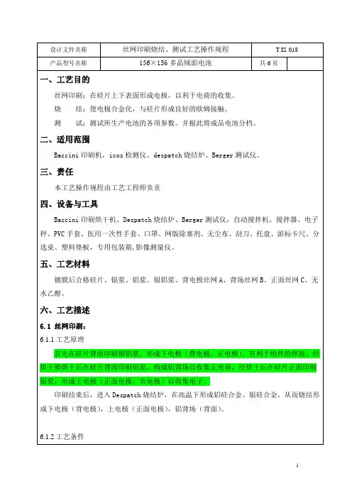
设计文件名称丝网印刷烧结、测试工艺操作规程T-IS-018产品型号名称156×156多晶绒面电池共6页一、工艺目的丝网印刷:在硅片上下表面形成电极,以利于电荷的收集。
烧结:使电极合金化,与硅片形成良好的欧姆接触。
测试:测试所生产电池的各项参数。
并据此将成品电池分档。
二、适用范围Baccini印刷机,icos检测仪、despatch烧结炉、Berger测试仪。
三、责任本工艺操作规程由工艺工程师负责四、设备与工具Baccini印刷烘干机、Despatch烧结炉、Berger测试仪,自动搅拌机、搅拌器、电子秤、PVC手套、医用一次性手套、口罩、网版除塞剂、无尘布、刮刀、托盘、游标卡尺、分选桌、塑料垫板,专用包装箱,影像测量仪。
五、工艺材料镀膜后合格硅片、银浆、铝浆、银铝浆、背电极丝网A、背场丝网B、正面丝网C、无水乙醇。
六、工艺描述6.1 丝网印刷:6.1.1工艺原理首先在硅片背面印刷银铝浆,形成下电极(背电极,正电极),有利于组件的焊接。
经烘干箱烘干后在硅片背面印刷铝浆,构成铝背场以收集正电荷,经烘干后在硅片正面印刷银浆,形成上电极(正面电极,负电极)以收集电子。
印刷结束后,进入Despatch烧结炉,在高温下形成铝硅合金、银硅合金,从而烧结形成下电极(背电极),上电极(正面电极),铝背场(背面)。
6.1.2工艺条件印刷线烘干抽气功率印一为:30%-50%,印二为 60%-80%烧结冷却水:PH值 7.2-7.6 入水16-20℃,压力150PSI,流量10GPM压缩空气:流量2700SCFH,压力60-70PSI6.1.3.注意事项:在印刷过程中应该调整适当的印刷压力、丝网和电池片之间的间隙和印刷速度。
C丝网更换周期为16小时(即隔班更换)。
印刷各项参数必须在规定范围内进行调整,如超出范围,需经技术人员同意,并做好相关记录,不得随意更改。
B丝网更换周期为24小时。
使用期间,根据铝浆印刷量调整参数,通常是调整丝网间隙、压力和印刷速度。
JRT Operating Instructions SPL DSP2Typ:DSP2 Machine no.:DSP2 Year of construe:2008JRT Photovoltaics GmbH & Co. KGRobert-Bosch-Str. 1 D-79331 Teningen Tel.: +49(0)7641 / 583-0 Fax: +49(0)7641 / 583-110www.jrt-pv.deGermany Operating InstructionsSolarprinter SPLJRT Operating Instructions SPL DSP2Basic instructionsBasic instructionsThese Operating Instructions describes the JRT Solar Printer Line DSP2.This is intended as a provisional document. A detailed and thoroughversion of the technical documents will be provided on delivery of thecomplete system.These SOP are a constituent part of the system. They must always bekept in the proximity of the system. Strict observation of the SOP is aprerequisite for the correct use and handling of the system and for thesafety of the operators which depends on this.All of the supplied technical information, care and maintenanceinstructions or separate instruction manuals for parts, components oraccessories must also be observed.Flawless functioning, safety during operation, and the least possiblenumber of disturbances are ensured only when used in combination withcomponents tested and approved by JRT.Use only accessories that were tested and approved by JRT together withthis machine. If third party accessories are used JRT cannot assume anyguarantee for the safe operation or reliable function of the system.There can be no guarantee claims in the event of damages caused by theuse of third party accessories.JRT only regards itself as responsible for the system in terms of safety,reliability and function if:installation, extensions, resetting, modifications and repairs arecarried out by a party expressly authorised by JRT or by JRT itself.the system is used in compliance with these SOP.All documents correspond to the version of the system and the state of thesafety standards on which it is based on going to print. All protective rightsare reserved for the devices, switches, processes, software programs,and names mentioned in the documentation.Duplication - even of extracts - is only permitted with the writtenpermission of JRT GmbH & Co. KG.The Basic safety instructions are marked in this manual as on page 4:Version history of the operating instructionsThe changes to the operating instructions and the change date arerecorded in this section in table form. The latest changes are always at thestart of the table.Date Changes02/15/2008Key word index (page 38) and version history (page 3) extended.Table of contents updated.02/14/2008Machine name changed. All headers and footers regenerated.Basic safety instructionsThese SOP contain safety instructions which must be observed to ensurepersonal safety and to avoid damage to property.The instructions for personal safety are emphasised by several additionalwarning and hazard symbols.Instructions regarding exclusively material damage or other importantinformation are not marked by warning symbols.Depending on the degree of risk, these are treated as follows:HAZARD Means that death, serious injury or substantial material damage willoccur if the corresponding precautionary measures are not taken.WARNING Means that death, serious injury or substantial material damage mayoccur if the corresponding precautionary measures are not taken.CAUTION Means that minor injury may occur if the correspondingprecautionary measures are not taken.NOTE Without a warning triangle means that material damage can occur if thecorresponding precautionary measures are not taken. This may be animportant or an informative instruction.NOTE The information “maximum workplace concentration” can be found in:Deutsche Forschungsgesellschaft, Kennedyallee 40, D-53175 Bonn.During normal operation, the noise level is 65 dB (A).The machine and accessories must be disposed of in accordance with thelocal regulations at the end of their service life. Besides the battery in theoperating panel and the lubricants (oils and greases), the machine doesnot contain any hazardous materials.In case of doubts, questions or service requirements, please contact:JRT GmbH & Co. KG Tel.: +49 (0) 7641 / 583-0Robert-Bosch-Str. 1Fax: +49 (0) 7641 / 583-110D-79331 Teningen www.jrt-pv.deGermany1 Use and functional setup1.1 Proper useBasic principles The system is built in accordance with the state of the art and therecognised safety standards. Nonetheless, its use can result in risks to thelife and health of the users or third parties, damage to the system itself orother material damage.Only use the system in technically perfect condition and for the intendedpurpose in a safety and risk-conscious manner and in accordance with theoperating instructions. In particular, any faults which could impair safetymust be rectified immediately!The JRT solar printer SPL-ALBATROS is used exclusively for the printingof solar cells (wafers). Only materials such as pastes, lacquers andcleaning agents with a flashpoint over 40 °C may be used. The pastesand cleaning agents may not be mechanically atomised even if theirflashpoint is above 40 °C.Adequate room ventilation must be provided.The machine is intended for commercial use only.Any other or more extensive usage is improper.Correct usage also includes:Strict observation of these short operating procedures / SOP.Personnel selection.and Work on the system may only be carried out by reliable, trained or qualification instructed personnel.Clear allocation of responsibilities. Obligation to supervise personnel intraining.Work on the electrical equipment of the system may only be carried out bya qualified electrician or by instructed personnel under the direction andsupervision of a qualified electrician in accordance with the electricalengineering regulations.Work on pneumatic equipment may only be carried out by personnelqualified for this purposeNOTE The JRT screen printing machines have diverse applications. They can beused to apply the widest possible range of pastes to the widest possiblerange of print materials. As we always draw up the performance featuresindividually for our customers, please note that the use of print materials orpastes other than those used in the projection phase can alter theperformance features cited in our offers.1.2 Functional setupThe cited item nos.:-1-to-8-are in fig.1.2.2on page 9.Rotary indexing table -1-On the rotary indexing table there are four print tables – so-called printnests-2-;-3-;-4-. The table turns by 90 °on every cycle, so that it movesto 4 positions in one rotation.Inlet station -5-In the inlet station the wafers are placed on the print table.A paper is spanned over the print table onto which the wafers are placed.The paper, which is rolled off a roll-6-behind the print tables and rolledonto a roll underneath the print table, has two tasks: on the one hand itconveys the wafers after printing onto the transport belt to thedownstream dryer, and on the other hand it ensures that the cells arealways placed on a clean underlay which is free of ink or other residues.After they are placed on the print table, the wafers are fixed by a vacuum. Print station -4-Here the wafers are printed using the screen printing process. The printstation consists mainly of the print head-9-with squeegee carriage-10-and the screen rails-11-.The print head can be raised for cleaning the underside of the screen.Two vertical positions are available: an upper and a middle position. Inboth positions the print head is mechanically locked for safety reasons toprevent unintended lowering.The squeegee pressure can be adjusted separately for the right and theleft cylinder. The pre-squeegee pressure cannot be changed. Thesqueegee bar is swivelled and can be passed over a drip channel-12-.1.2 Functional setup Item no.Fig. 1.2.1Designation -9-Printing head -10-squeegee carriage -11-Screen rail -12-Drip channel -13-Squeegee pressure cylinder Printing cycle Lowering the print headPrinting the material by advancing the squeegeeRaising the print headFlooding the screen by returning the flood bar.Register setting (screen alignment) is automatic.Outlet station Item3 on the rotaryindexing table The camera over the output station (optional) checks the print quality and the condition of the wafer. Only predefined print errors are recognised by the camera. Damaged wafers are removed.To output the wafers the paper is rolled off the upper roll until the solar cells have reached the connecting transport belt.The machine is controlled via an operating panel with monitor.As required by the applicable directives, all moving or rotating parts are secured with technical protective measures.Fig. 1.2.2on page 9 shows the main components of the JRT solar printer SPL-ALBATROS.1.2 Functional setupItem no.Fig. 1.2.2Designation -1-Rotary indexing table -2-Inlet station -3-Paper control station -4-Print station -5-Paper roll -6-Outlet station with camera (optional)-7-Jockey roller on the paper transport system Fig. 1.2.2 Solarprinter Aufbau3 The operating panelThe machine is equipped with a SIMATIC control system and is operatedby mouse and keyboard. Operation is menu aided, i.e. related settings aregrouped respectively in a menu window on the screen.In all of the menu windows the lower section always shows the standardoperating keys(see page 18) with which you can execute the mostfrequent operating steps.You actuate the buttons by clicking on them with the mouse.To enter values, click on the entry field. A keyboard is displayed withwhich you can make all of the necessary entries. Use the enter key toconfirm the entry and remove the keyboard from the screen.The operating panel also contains the key to switch on the control systemand an emergency stop switch.4 The menusBasic principles This chapter briefly introduces the individual menus.Reminder:The control system is menu aided, i.e. related settings are groupedrespectively in a menu window on the screen.In the following section Machine setup(see page 20) you can read howthe machine is started up and which settings have to be made in themenusNOTE The individual menus are called up by clicking on the corresponding button;the buttons shown in the menus are actuated in the same way.To enter values or text, click on the entry field. A keyboard is displayedwith which you can make all of the necessary entries. Use the enter keyto confirm the entry and close the keyboard.In all of the menus the standard operating keys are shown on the lowersoftkey bar on the screen (see page 18), e.g.Automatic ON/OFF,Automatic START/STOP or Starting position.JRT Operating Instructions SPL DSP2Once the system is booted up, the system start window appears. Click on The control system is booted up and theappears.the function of the individual stations pending error messages and warnings The other menus for printer, dryer etc. can be called up with the buttonsbelow the header.On page 15 you will find a detailed description of the individual functionsin correspondence to the numbers on this page (14).JRT Operating InstructionsSPL DSP21In the system overview window you can call up the other individual menus on the menu bar at the top. These are: printer, dryer, statistics, miscellaneous and fault reports2List with fault reports. Fault reports cause a shutdown of the machine.3List with warning reports.4To select the machine setting.5To load the corresponding machine settings in the machine control system.6Diagram of rotary indexing table (middle) and the four stations: print station, inlet station, paper control station, outlet station; the red panel symbolises the switched-on camera lighting. Numbers displayedrepresent the individual print nests. When the rotary indexing table turns, the print nest numbers turn with it.7Diagram of the trapdoor (to remove rejected parts).8Diagram of the synchronising belt.9Extreme left: result for the last wafer, then the result for the second last etc.10List of pending reports (fault or warning reports).11To confirm reports.12Control lamps dryer, cooling zone green: temperature OKyellow: heating/cooling red: fault13Control lamps dryer, heating zone. green: temperature OKyellow: heating/cooling red: fault14Control lamps dryer belt. green: speed OKred: fault15To switch the dryer belt on and off.16Standard operating keys.17Function control inlet, print and outlet station as well as paper control and rotary indexing table. yellow: station working green: station has workedred: fault18To start automatically (e.g. after a change of screen) the machine moves to the basic position, automatic mode is switched on and the machine starts up.19To call up the camera image (screen centering) on the separate monitor. 20To initiate a change of screen. Automatic operation stops. Squeegee carriage is raised and passes over the drip channel. The screen frame clamp opens.21To start the automatic screen alignment process.22Last fault occurringDisplay of the information You can display detailed information for the individual stations.windowA window appears in each case with two lines:The first line shows the current action.The second line shows the conditions for the next action.The control lamps below indicate the function of the step chain.To display the information window, click on the symbol of the station andselect Open / close information. Use the same procedure to close theinformation window.Fig. 4.2 SYSTEM OVERVIEW Open /close informationSwitch step mode on / off You can switch on step mode to make settings at the individual stations.The buttons Reset and Step forwards are displayed.To switch step mode on, click on the icon for the station and select Stepmode on /off. You can switch the step mode off in the same wayFig. 4.3 Menu SYSTEM OVERVIEW Switch step mode on / off Attention!If step mode is activated you have to continue through the individual stepson the step chain by individual clicks on the corresponding button.The machine comes to a standstill after every step.Standard operating keys. The lower standard operating keys bar is the same in all menu windows1 Automatic ON/OFF.To switch from manual to automatic mode.You can only switch to automatic mode if the machine is in the startingposition. In automatic mode, pressing Automatic START/STOP triggersthe print cycles automatically until the machine is stopped by pressingAutomatic START/STOP2 Automatic START/STOP For starting and stopping the machine in automatic mode.3 Squeegee forwards / back To move the squeegee in manual operation (Automatic START/STOP is not pressed). The squeegee carriage moves forwards to the end position and then back again.4 Screen cleaning.To activate the screen cleaning (before the print head can be raised withFrame UP / DOWN,Clean screen must be pressed). To lower the printhead you must press either the button Starting position or Frame UP /DOWN.The function ”Clean screen” is automatically deactivated5 Swivel squeegee Use this to swivel the squeegee bar upwards and pass it over the dripchannels.When you press key5:the squeegee carriage moves to the centre of the print headthe squeegee bar swivels upwardsthe squeegee carriage waits for the drip-off timethe squeegee carriage passes over the drip channelWhen you press the key again:the squeegee carriage moves to the centre of the print headthe squeegee bar swivels downward6 Starting positionBrings the machine to the starting position. While approaching the startingposition, the key flashes green. As soon as starting position is reached,the key is permanently lit in green.7 Dryer ON/OFF To switch the dryer on and off.8 Screen clamp To open and close the screen frame clamp.9 Squeegee forward Causes the squeegee carriage to remain in the position “print end” afterevery print (screen open).10 Frame UP / DOWN To raise or lower the print head in setup mode or to raise and lower theprint head for cleaning the screen or changing the paper roll.5 Adjusting the machine5.1 Referencing, bringing the machine to the starting positionWARNING Risk of injury due to moving machine parts.Serious physical injury to head and hands by crushing or severingof body parts.Before switching on (start-up) the machine (system), make surethat nobody is working on or in the machine.Close the protective doors.Apply safety and protection covers.After actuating the main switch, the drives for print head, squeegeecarriage and screen lift have to execute a reference motion.Only then can the machine be brought to the starting position.Switch on compressed air supply.Actuate main switch.First the start information window appears.The system is booting up! Please wait.After booting up, the start window appears on the screen.The system overview window is opened by mouse click on the softkeySystem loaded!Fig. 5.1.1 System loaded5.1 Referencing, bringing the machine to the starting positionFig. 5.1.2 SYSTEM OVERVIEW Switch on the control system at the control panel. The illuminated button must be lit up.Click on the Starting position key.The machine now carries out a reference motion with the print head, i.e. the print head is raised to the end position where it remains. During the reference motion the button Starting positionflashes. Click on Starting position once more.The print head. is lowered and remains in the position “raised”.Click on Starting position once more.Now the squeegee carriage and the screen lift carry out a reference motion.Click on Starting position once more.The squeegee carriage moves forward to the position “print end”. The machine has reached its starting position and the button Starting position is lit permanently in green5.2 Inserting screenClick on the button Printer in the system overview window. The windowPRINTER – print parameters appears. Click on the button Setup in theupper standard operating key bar and the window PRINTER – setupappears(Fig. 5.2.1).Fig. 5.2.1 PRINTER - setupOpen the screen clamp.Insert screen.Close the screen clamp again. The screen frame is alignedautomatically.5.3 Inserting the squeegee Press the softkey Squeegee forwards / back on the lower standard operating key bar to move the squeegee carriage to a favourable position for inserting the squeegee.Select a squeegee of the appropriate length.The squeegee should extend beyond both sides of the printed image by approximately 20 mm.The maximum length of the squeegee depends on the size of the screen frame.. Maintain a distance of at least 100 mm between the end of the squeegee and the screen frame. Make sure that the two swivel plates are set at the same squeegeeangle. If not, this can be corrected using the clamp lever.Insert the flood bar (front) and the printing squeegee (rear) into theclamping receivers and tighten the clamping levers (6).Make sure that the squeegee is under symmetrical tension and does not protrude to the right and left more than 25% of the total lengthBefore switching on (start-up) the machine (system), make sure that nobody is working on the squeegee cylinders.If the controller fails, the cylinders may raise or lowerunpredictably. For this reason, switch off the main switch before performing adjustment work that requires a longer amount of time.If the cylinders were moved manually while the power wasswitched off (like when the main switch is switched off), they will return to the previously selected position when the power is turned back on.WARNING Risk of injury due to moving machine parts.Serious physical injury to head and hands by crushing or severing of body parts.5.4 Setting the print parametersEntering the print and Click on the softkey Print parameters in the upper softkey bar to flood speed.open the PRINTER - print parameters windowClick on the entry panel-1- print speed and used the keyboarddisplayed to enter the starting value 100 mm/s (input range 100 (400)mm/s).Press the enter key J+to confirm the entry. This also closes thekeyboard.Proceed in the same way for-2- flood speed.Fig. 5.4.1 PRINTER – print parameters Print speed / Flood speed5.4 Setting the print parametersAdjusting the SqueegeeYou can set the squeegee path in two ways:Stroke . 1. By driving the squeegee carriage to the front and back end positionand then storing the respective position by pressing a key.2. By entering the front (print start) and rear (print end) end position as anumerical value in the squeegee menu NOTERisk of the squeegee arm colliding with the screen frame.Damage to the squeegee and the screen frame. Whenever possible, always set the squeegee path by moving the squeegee carriage.1. Moving the squeegeecarriage and storingthe end position (Fig. 5.4.1) Move the squeegee carriage with -3- Squeegee forwards /back to the print start and press-4- Teach In Start.Then move the squeegee carriage to the print end and press -5-Teach In End .Fig. 5.4.1 PRINTER – print parameters Teach In Start / End HAZARD Insufficient minimum distance at the end positions betweensqueegee and screen frame.Increased risk of crushing injury to hands.The distance between the squeegee and the screen framemust not be less than 25 mm.5.4 Setting the print parameters2. Entering end positions Click on the entry panel-6- Position print start end enter the value (theas numerical values value is entered in mm and measured from the rear end stop of the (Fig. 5.4.2)squeegee carriagePress the enter key J+to confirm the entry.Proceed in the same way for-7- Position print endFig. 5.4.2 PRINTER – print parameters Position print start / print end5.5 Changing the paper rollTo change the paper roll, the corresponding print nest must be in the printstation.When the system demands a change of paper, click on the softkey-1-Request paper change in the menu PRINTER – print parameters (Fig.5.5.1).The machine continues running until the corresponding print nest is in theprint station. The machine stops and the print head moves upwards intothe cleaning position.-1-Fig. 5.5.1 PRINTER – print parameters Request paper change5.5 Changing the paper rollOpen the holder for the take-up roll. To do this lift the locking lever and slide itto the right (Fig 5.5.1). Remove the roll to be changed.Fig. 5.5.1 Locking lever to open the holderPlace the new roll on the lower tray (Fig. 5.5.2).Fig. 5.5.2 Inserting the new roll5.5 Changing the paper rollStick the end of the paper (Fig. 5.5.3) to the end of the take-up roll withadhesive tape and wind on some paper with a few turns.Insert the take-up roller. and close the holderFig. 5.5.3 Sticking the end of the paper to the take-up roll.Wind on paper with a few turns.Now grip the new roll and lead the paper under the jockey roller and overthe print head (Fig. 5.5.4).Place the new roll into the holder after the print head and close the lockinglever.Fig. 5.5.4 Thread paper under the jockey roller Fasten the roll on the rear holder.5.5 Changing the paper rollSwitch to the submenu Manual control.Use the symbol key at-1- Take-up roll in the paper transport window to windon paper until the jockey roller has reached the upper position (Fig. 5.5.5).Fig. 5.5.5. PRINTER – Manual control Take-up roll5.6 Working on the underside of the screen To carry out work on the underside of the screen, the whole print head can be raised.There are two positions to choose from: one at the top and one around the middle. You can select the position in the submenu print parameters.Make sure that the print head reaches this position and stops automatically. Only in these positions is the print head mechanically locked and is thus secured against unintentional lowering. Click onStarting position. Click on Clean screen . Click on Frame UP / DOWN .The print head is raised into the cleaning position. Wait until the print head reaches its end position and all movement has stopped. Move the print head to the end position. Then the print head is mechanically locked and thus prevented from unintentional lowering.Now you can open the door and begin work.After work is completed you must close the door and either press Starting position or Frame UP / DOWN . The Clean screen function is automatically deactivated.If you would like to clean the screen during automatic mode you only have to click on Clean screen : the machine stops. the squeegee carriage stops in the forwards position (screen notflooded). The print head is raised into the cleaning position.When work is completed, press: Basic position Automatic ON/OFF Automatic START/STOP HAZARDPrint head not in end position.Increased crushing risk for head, neck and hands.5.7 Storing and loading machine settingsIn the menu PRINTER – print parameters you can store machine settingsunder a data set name or reload them using this data set name.In the window Recipe administration Printer you can enter thecorresponding data.Storing settings Make all of the machine settings.Click on key-1-(see Fig. 5.7.2on page 33).Load the data from the machine control system with the key-4-.Enter a data set name in the entry panel-6-.Store the data with one of the keys-2-.Load settings Enter the data set name under which the settings are stored in theentry panel-6-or select it with-7-.Use key-5-to load the data in the machine control system.The loaded settings appear in the table column Value(see item no.-8-onpage 32).Delete stored machine settingsEnter the data set name under which the settings are stored in the entry panel-6-or select it with-7-.Use the key-3-to delete the settings.Fig. 5.7.1 PRINTER – print parameters Recipe administration Printer5.7 Storing and loading machine settingsFig. 5.7.2 Recipe administration Printer5.8 Selecting a languageThe language of the display texts can be selected in the Miscellaneous menuby clicking on key-1- Select language(Fig. 5.8.1).Fig.5.-1-8.1MISCELLANEOUFig. 5.8.1.MISCELLANEOUS Select language6 Automatic mode 6.1PrintingSet up the machine (see Chapter 5, page 20). Add paste.Click on the softkey -1- Start position .Select automatic mode with -2- Automatic ON/OFF . Start automatic mode with -3- Automatic START/STOP .You can also start the machine by simply clicking on-4- Machine START . With this key the starting process is executed automatically:The machine moves to the starting position. Automatic mode is selected. The machine starts running.-Fig. 6.1.1 SYSTEM OVERVIEW Print-4--3--2--1-。
![太阳能硅电池片丝网印刷装置及印刷方法[发明专利]](https://uimg.taocdn.com/f9ec54f0866fb84ae55c8d84.webp)
2019运动会通讯稿100字【十篇】运动场上有你飒爽的英姿;运动场上有你拼搏的身影。
面对着漫漫征途,你没有畏惧和退缩。
任汗水大湿脊背;任疲惫爬满全身;你依然奋力追赶,只有一个目标;只有一个信念为了班级的荣誉,拼搏吧!快去击败困难、快去夺取胜利!千百双眼睛在注视着你们,希望就在前面,加油啊,运动健儿们,胜利就在前面。
一根细细的杆子横放在半空中,它细,然而却像你生命中的坎,不可怕,不要怕,只要你有决心,只要你有信心,这又算得了什么?没有经历过坎坷就不会有成功的喜悦,一次次的战胜,一次次的超越自己,加油吧,努力跳过这挡在你前面的坎去燃烧你的青春!篇三热情地释放光芒的红日,被阵阵此起彼伏的加油声震撼,慌张地投入到乌云的怀抱那群北飞的候鸟却因为热火朝天的场面而盘旋在运动场上,留恋着这里与寂静的天空截然不同的热闹围绕在运动场边的树木,在秋风的频繁光顾下奏鸣出悦耳的树叶的交响曲,仿佛是为了配合场上的拉拉队,为奋斗的运动员们加油鼓劲篇三短暂的一瞬间,显示出你惊人的速度,铿锵有力的一声吼叫,把你全身的力量都凝聚在这一刻上努力吧!加油啊!时间短暂并不代表你激情短暂,距离不长却表示你成功不远,相信自己,冲啊!胜利就在眼前,失去不会再现!篇四一条跑道,要四个人去打造一个信念,要四个人去拼搏!每次交接都是信任的传递!每次交接都是永恒的支持!前世的五百次回眸,才能够换来今天的相遇,冲吧!向着终点,向着个四个人的共同目标,前进!篇五漫漫长路,你愿一人独撑,忍受着孤独与寂寞,承受着体力与精神的压迫,任汗水溶于泪水,可脚步却从不停歇。
好样的,纵然得不了桂冠,可坚持的你,定会赢得最后的掌声篇六深深的呼吸,等待你的是艰难的5000米。
相信胜利会属于你们。
但在这征途上,需要你用勇敢的心去面对。
我们在为你加油,你是否听到了我们发自心中的呐喊? 困难和胜利都在向你招手,去呀,快去呀,不要犹豫。
快去击败困难、快去夺取胜利!相信你会送给我们一个汗水浸湿的微笑!篇七磨炼的是非凡的毅力,较量的是超常的体力,拼搏的是出类拔萃的耐力。


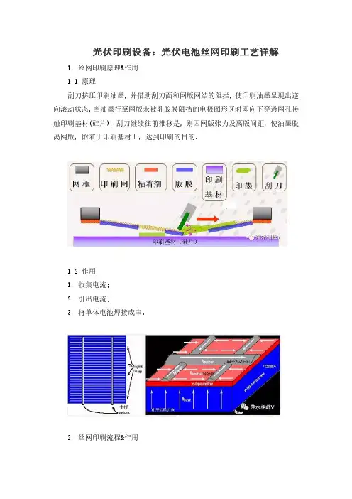
光伏印刷设备:光伏电池丝网印刷工艺详解1.丝网印刷原理&作用1.1原理刮刀挤压印刷油墨,并借助刮刀面和网版网结的阻拦,使印刷油墨呈现出逆向滚动状态,当油墨行至网版未被乳胶膜阻挡的电极图形区时即向下穿透网孔接触印刷基材(硅片),刮刀继续往前推移是,则因网版张力及离版间距,使油墨脱离网版,附着于印刷基材上,达到印刷的目的。
1.2作用1.收集电流;2.引出电流;3.将单体电池焊接成串。
2.丝网印刷流程&作用2.1印刷流程2.2背电极印刷a.作用:形成良好的欧姆接触特性、焊接性能和附着性;b.银浆组成:银铝浆是由银粉,铝粉,无机添加物和有机载体组成;c.印刷参数:在印刷图形完好时,印刷头压力在范围内尽可能的小。
2.3背电场印刷1.作用a.形成P+结区,使到达P/P+结的长波光子所激发的光生载流子对被P/P+结分离,增加少子扩散能力,提高开路电压。
b.P/P+结可阻止P区光生电子到背表面复合,与没有P+区相比较,这种高低结P/P+结构可大大降低背表面的复合速率。
c.P+区的存在可制作良好的欧姆接触。
2.银浆组成铝浆由铝粉,无机添加物和有机载体组成;3.印刷参数影响所印铝浆的厚度因素有:丝网目数、网线直径、开孔率、乳胶层厚度、印刷头压力、印刷头硬度、印刷速度及浆料粘度。
2.4正面栅极印刷a.作用:形成良好的欧姆接触特性、焊接性能和附着性,收集电流,引出电流。
b.银浆组成:正面栅极银浆是由银粉,无机添加物和有机载体组成的。
c.印刷参数:参数的调整以图形完整、线条饱满、印刷浆料重量适当为基准。
3.丝网网版&刮条3.1丝网网版调整1.在保证印刷质量的前提下,网版间距越小越好;2.一般为(-900~-1300)μm;3.太小易粘版或模糊不清,过大易印刷不良和损坏网版;4.印第二道时可适当加大间距。
3.2刮条调整1.在保证印刷质量的前提下,刮条下降深度和压力越小越好;2.刮条深度一般为(-900~-1300)μm;3.刮条下降过深或压力过大,易碎片和损坏网版;4.刮条下降深度不够或压力太小易印刷不良或粘版。
太阳能电池丝网印刷新技术填补国内空白作者:暂无
来源:《网印工业》 2015年第2期
丝网印刷是太阳能电池制造的重要工艺,它质量的好坏会对太阳能电池的性能特别是电性能产生重要影响。
据悉,迈为技术有限公司新研发的太阳能电池丝网印刷“超级单线SSL-65K”设备技术取得突破,达到了国际领先水平,打破了光伏行业丝网印刷设备完全依赖进口的局面,填补了国内空白。
以往光伏产业太阳能电池丝网印刷设备几乎全部都由国外进口,吴江迈为技术有限公司从2008年便开始着手研发该行业高端设备,此次新发布的“超级单线SSL-65K”大大节省了电力与时间,使产量从原先的40000片/日迅速升为65000片/日。
该设备只要多花20%的电费,20%的人工以及10%的占地面积,就可以增加80%的产量。
包装印刷太阳能电池丝网印刷技术引言随着环境意识的提高和可再生能源的重要性日益增加,太阳能电池在能源行业中的应用得到了广泛关注。
而包装印刷太阳能电池丝网印刷技术作为一种关键的制备技术,被广泛应用于太阳能电池的制造过程中。
本文将介绍包装印刷太阳能电池丝网印刷技术的基本原理、关键步骤及其在太阳能电池制造中的应用。
1. 基本原理包装印刷太阳能电池丝网印刷技术是一种利用丝网印刷技术制备太阳能电池的方法。
其基本原理是利用特制的丝网,通过将电子浆料转印到太阳能电池基板上,形成太阳能电池的导电层或电极。
该技术的核心在于丝网印刷机,它由传送系统、丝网印刷系统和固化系统三部分组成。
其中,传送系统用于将基板顺序送入机器,丝网印刷系统负责将浆料通过丝网转印到基板上,固化系统则用于固化印刷而形成的导电层或电极。
2. 关键步骤包装印刷太阳能电池丝网印刷技术的关键步骤如下:步骤一:基板准备首先,需要准备好太阳能电池的基板。
通常采用的基板材料包括硅基板和聚酰亚胺基板。
这些基板需要经过一系列的清洗和处理过程,以保证表面的洁净和光滑。
步骤二:浆料制备其次,需要制备好电子浆料。
电子浆料通常由导电粒子、有机高分子和溶剂等组成。
在制备过程中,需要将这些材料按照一定的比例混合,并通过搅拌或超声处理,使其生成均匀的浆料。
步骤三:丝网印刷接下来,将准备好的电子浆料倒入丝网印刷机的供墨槽中。
然后,将基板送入丝网印刷机,通过控制丝网印刷机的运行速度和压力,可以使电子浆料通过丝网转印到基板上。
在转印过程中,丝网的尺寸和形状决定了浆料的转印面积和形态。
步骤四:固化最后,将印刷而形成的导电层或电极进行固化。
通常采用的固化方式有烘干、烧结、紫外线照射等。
固化的目的是使浆料中的溶剂挥发,使导电粒子与基板之间形成牢固的结合。
3. 应用包装印刷太阳能电池丝网印刷技术在太阳能电池制造过程中起着至关重要的作用。
其应用主要体现在以下几个方面:1.制备导电层或电极:通过丝网印刷技术,可以将电子浆料转印到基板上,形成太阳能电池的导电层或电极,从而实现电流的导通功能。