DinoCapture2.0显微镜使用手册
- 格式:pdf
- 大小:2.54 MB
- 文档页数:74
显微镜的操作规程操作规程:1、实验时要把显微镜放在座前桌面上稍偏左的位置,镜座应距桌沿6~7cm左右。
2、打开光源开关,调节光强到合适大小。
3、转动物镜转换器,使低倍镜头正对载物台上的通光孔。
先把镜头调节至距载物台1~2cm左右处,然后用左眼注视目镜内,接着调节聚光器的高度,把孔径光阑调至最大,使光线通过聚光器入射到镜筒内,这时视野内呈明亮的状态。
4、将所要观察的玻片放在载物台上,使玻片中被观察的部分位于通光孔的正中央,然后用标本夹夹好载玻片。
5、先用低倍镜观察全景,再转高倍镜进行局部观察。
从低倍转到高倍镜时,必须在低倍镜下目视转移到视野中心,然后把镜筒转上,再转动物镜转盘,将高倍镜对准标本,然后调节焦距。
6、镜检时,须两眼同时睁开,用左眼观察,以便右眼以绘图或记录。
7、使用完毕,进行使用登记。
注意事项:1、显微镜要安装在坚固、平坦桌面或工作台上,不要堵塞镜基下面的通风口。
2、使用前要仔细阅读厂家提供的使用说明书。
显微镜后表面的灯室表面会非常热,安装显微镜时,要在周围特别是灯室上方保留充分的散热空间(10厘米以上)。
3、安装显微镜时,让电源线远离灯室,如果电源线接触到灯室,电源线会因为受热而熔化,造成触电。
4、更换灯泡时需关闭电源,拔出电源线,以免触电或着火,如果显微镜使用中或刚刚使用后,要等到灯座和灯泡冷却后才能更换灯泡。
5、移动显微镜时,要用双手小心地握住镜臂和镜基后面的把手,操作时要小心,并避免突然或剧烈的震动。
6、清洁镜头时,先用吹气球将灰尘吹去,然后用镜头纸轻轻擦拭。
如要除掉指纹或油渍,可蘸取少量无水酒精擦试。
7、不要使用有机溶剂擦拭玻璃部件以外的显微镜其他部件。
如果要清洁这些部件,请使用一块无毛柔软的布蘸少量中性清洁剂擦拭。
8、不使用显微镜时,请用防尘罩盖上。
化验室显微镜使用说明
1.再下底盘的右侧印有电源的开和关的标志符号,按照标志打开即可。
2.转动粗动手轮,使载物台降低到适当位置。
扳动片夹手柄,把被观察载玻片轻轻夹在载物台上,转动载物台横向或纵向转动手轮,将载玻片移入光路。
3.选择10X物镜,转动转换器,听到咔哒声音表示已将其转入光路。
4.对于单目型产品,只用单目观察,先用梢快速度转动粗动手轮,知道眼睛从目镜里观察到标本像的大致轮廓为止,然后慢慢转动微调手轮,使成像清晰。
5.对于双目产品,双目观察头有滑扳双目组和转轴双目组两种,双手向两侧拉动滑扳双目头的左右盖扳,以右盖扳的左端面对准刻度板上的瞳距刻度,调节两目镜管之间的出瞳距离,使之与观察者两眼的瞳距相匹配,转动右目镜管上的长补偿圈,使其对准的刻度值与瞳距刻度相一致。
6.调节双目成像过程与单目基本一样,先找到轮廓,再慢慢的转动微动手轮,有右眼从右目镜里观察,使标本像越来越清晰,直到满意为止。
7.然后用左眼从左目镜里观察,稍微转动左目镜管的筒长补偿调节圈,使左右双眼看到的标本像一样清晰。
8.松紧调节圈的使用:松紧调节圈可以调节粗微动组的松紧,防止载物台自行下滑,同时增加粗微动操作上的舒适感,顺时针旋转,可以
发送,相反,可以锁紧。
9.物镜的选择:根据需要可以随时变换不同发大倍数的物镜,转动转换器,将锁需物镜转入光路。
LED indicator lightKnurled diopter collarEyepiece tube housing Eyepiece tubeEyepiece locking set screwEyepiecesHeadFocusing knobObjective turretTop light housing BaseStage plateStage clipsUSB jackPower switch switchesDC outputEyepiece rubber shieldsAbout the Digital MicroscopeYour new digital stereomicroscope incorporates a built in camera that utilizes ultra high-speed data transmission made possible through a simple plug and play USB 2.0 cable. Your stereoscopic microscope can be used independent of the camera so that you can view 3 dimensional objects, inspection or assembly of small pats, and for dissection of biological specimen. They provide upright, un-reversed image that permits easy manipulation of the object being viewed while looking through the microscope. They are designed for viewing solid objects at low magnification, but they will also permit viewing of some transparent specimen slides.UNPACKING1. Your microscope is packed with the following components, all of which have been checked at the factory.Do not touch any of the lens surfaces while handling the microscope. Dust, dirt, fingerprints can damage the delicate lens surfaces or adversely affect image quality. Carefully remove all components and check against this list.A. Microscope with WF10x eyepieces (pair) already installedB. Instruction manualC. CD Motic Images softwareD. Calibration slideE. 12VDC switching power supply, operates on 100v-240v, 50H/60HF. AC power cordG. USB 2.0 cable (for connecting to computer)H. Rubber eyecups (pair)I. Two 80mm stage plates: plastic white & frosted glass (one installed)J. 1.27mm “L” type hex wrench (for tightening stage plate locking screw)K. Pin spanner wrench (for turning tension adjustment collar)L. Dustcover2. Examine packing material before you discard it. Retain the Styrofoam container in case you need totransport, store or return the microscope for service. If it becomes necessary to ship the microscope for any reason, repack it in the styrofoam container, and then pack the styrofoam in another corrugated shipping container for optimum protection. Use of the styrofoam alone will not provide adequate protection in transit, and will void your warranty.DESCRIPTION OF COMPONENTS1. LED INDICATOR LIGHT: Indicates if camera is on. The LED lamp is illuminated after microscope isconnected to computer with USB 2.0 cable and camera is turned on by software commands.2. WIDEFIELD 10X EYEPIECES: Lens closest to the eye, magnifies the primary image formed by theobjective lens.3. RUBBER EYEGUARDS: These help block out undesired light reflections, and to position your eyes at theproper point above the eyepieces.4. EYEPIECE LOCKING SET SCREW: Prevents removal of eyepiece. In secure environment, locking screwsare not required.5. KNURLED DIOPTER COLLAR: On one eyepiece only, for adjusting microscope to each individual’s vision.See operating instructions.6. HEAD RETAINING SCREW: Locks head of microscope in a fixed position, to protect camera components,7. OBJECTIVE TURRET: Turns 90° to change magnification of microscope. Number positioned at front ofmicroscope indicates objective power in use.8. FOCUSING KNOBS: For focusing image seen through microscope and camera. Tension adjustment collaris located between knob on one side and arm of microscope.9. TOP LIGHT HOUSING: Covers incidental (top) light of microscope.10. STAGE PLATE: 80mm stage plate secured by locking setscrew located on one side of base. Both whiteplastic and frosted glass plates are included.11. MAIN POWER SWITCH: Turns power to microscope on and off.12. LIGHT CONTROLS: “I” controls incidental (top) light and “T” controls transmitted (bottom) light. When “T”(bottom) light is in use, frosted glass plate MUST be in place.13. 12VDC POWER CORD/CONVERTER: Accepts 100v-240v 50H/60H input and supplies 12VDC power tothe microscope. Note that this converter accommodates either 120v or 240v and 50H or 60H power supply, eliminating the need for any other transformer.14. USB JACK: USB 2.0 cable connection.ASSEMBLYYour microscope comes fully assembled, except minor parts.1. Slip rubber eyeguards over top edge of eyepieces, with flared portion positioned at the outside edge ofeyepieces. These help block out undesired light reflections, and to position your eyes at the proper point above the eyepieces.2. Plug detachable power supply cord into the 12VDC switching power converter, then into power outlet. Notethat the switching power converter will accept 120v or 240v current, 50H/60H, and no other transformer is required. Then plug jack on other end of power converter into port on back of microscope base.3. Two 80mm stage plates are furnished. The frosted glass plate is used when viewing transparent specimenslides, or for viewing some specimen thin enough through which light can pass. The white plastic plate can be used when viewing opaque objects or for dissecting.NOTE: FROSTED GLASS PLATE MUST BE USED IF USING BOTTOM ILLUMINATION. HEATGENERATED IN BASE FROM BOTTOM LIGHT WILL WARP OR DAMAGE WHITE PLASTIC PLATE.SUCH DAMAGE WILL NOT BE COVERED BY WARRANTY.It is acceptable to leave the glass plate in place for most viewing. To switch plates, use the “L” hex wrench to loosen setscrew at side of base, only enough to permit removal of stage plate. Replace stage plate and retighten setscrew.OPERATION1. There are three rocker type light controls located on top surface of microscope base:MAIN = Turns power to light selector switches on and off“I” = Turns incidental light on (top illumination)“T” = Turns transmitted light on (substage illumination)2. Turn MAIN power switch to ON position and select appropriate illumination for your specimen.3. Adjust the interpupillary distance between eyepieces to match that of your own eyes. Looking throughmicroscope will both eyes, grasp both sides of microscope head and gently push eyepiece tube housings together or pull apart until the two images blend into one image.4. Turn objective turret until small number (lowest magnification) is towards front of microscope (away fromarm), making certain that turret “clicks” into indexed position.5. Magnification is determined by multiplying the number on the eyepieces times the number on the objectiveturret. For example, your microscope is supplied with WF10x eyepieces, when the “3x” on the objective turret is facing to the front of the microscope, the magnification resulting will be 30 times.To change magnification, turn objective turret 90° until it clicks into indexed position with another number on turret facing to front of microscope. Your microscope is parfocalled, and only slight adjustment of thefocusing knobs may be required after changing from one magnification to the other.Use of eyepieces other than WF10x will affect microscope magnification according to the chart above, only as viewed through the microscope. The digital camera has built in lenses and therefore, use of othereyepieces on the microscope will not affect image magnification as viewed on the computer monitor.Any reticle installed in eyepiece will be visible only when viewing through microscope, and will not be visible on computer or video monitor.6. Place object to be viewed on center of stage surface.7. Turn the focusing knobs until object being viewed is in focus.8. Looking through right side of microscope with right eye, adjust image sharpness by turning the focusingknobs.9. Looking through left side of microscope with left eye, turn diopter adjustment collar located on left eyepieceuntil left image is sharp. Note the scale on the diopter collar and its position in relationship to the index mark on the eyepiece tube.You have now adjusted the microscope for your personal vision. When viewing other objects ofvarious sizes, you should not have to make further adjustment of the diopter, and will need onlyto adjust the focus knobs. If other users change the diopter setting for their vision, you need onlyto return the diopter scale to your setting in order for it to once again be adjusted for your vision.10. For optimum sharpness of image in the entire field of view, it is important to position your eyes at the correctpoint above the eyepieces. Looking through both eyepieces, slowly move your eyes towards eyepieces to a level where clarity of the entire field of view is achieved. After a brief period of viewing, you will easily find the best point for your vision.MAINTENANCEWARNING: For your own safety, turn switch off and remove plug from power source before maintaining your microscope. If the power cord is worn, cut or damaged in any way, have it replaced immediately to avoid shock or fire hazard.1. OPTICAL MAINTENANCEA. Do not attempt to disassemble any lens components. Consult a microscope service technician whenany repairs not covered by instructions are needed.B. Prior to cleaning any lens surface, brush dust or lint off lens surface using a camel hair brush. You canalso use an ear syringe or canned compressed air, such as that sold by most computer stores.C. To clean eyepiece lenses, do not remove from eyepiece tube. Clean only the outer lens surface.Breathe on lens to dampen surface, then wipe with lens paper or tissue or use a cotton swab moistened with distilled water. Wipe lenses with a circular motion, applying as little pressure as possible. Avoidwiping dry lens surface as lenses are scratched easily. If excessive dirt or grease gets on lens surfaces,a small amount of distilled water or Windex can be used on a cotton swab or lens tissue. To cleanobjective lenses, do not remove objectives from microscope. Clean front lens element only, followingsame procedure.2. MECHANICAL MAINTENANCEThe only mechanical adjustment you might ever require is the tension of the focusing mechanism. This has been adjusted at the factory, but over the course of time it may loosen and cause the head of themicroscope to slip downward on the focusing block.To adjust, observe that stem of focus knob on one side of microscope has a tension adjustment collar with four small holes. Only one of these holes contains a small set screw. Using a small jewelers screwdriver, loosen this setscrew. Turn collar clockwise to tighten tension, counter-clockwise to loosen tension. Use of a large rubber band placed around the collar will permit you to grip the collar and turn it by hand in order to accomplish the adjustment. After adjusting, tighten the small setscrew to lock collar in place.NOTE: It is recommended that you leave the tension as loose as possible for ease of focusing, yet not so loose that it permits the head of microscope to drift downward from its own weight and cause the microscope to “drift” out of focus.3. ELECTRICAL MAINTENANCEThe extent of electrical maintenance, by other than a qualified technician, should be bulb replacement. BE CERTAIN TO TURN SWITCHES OFF AND REMOVE PLUG FROM POWER SOURCE OUTLET BEFORE CHANGING BULBS. After unplugging microscope, ALLOW SUFFICIENT TIME FOR LAMP HOUSING TO COOL COMPLETELY.A. To replace top lamp:The top lamp requires a 12 volt 10 watt halogen bulb, a common microscope bulb available from yourdealer (National part #800-423)For easy access to the lamp housing, gently lay microscope on its side. Remove black lamp housing by rotating in a counter-clockwise direction. Using a tissue or cloth, gently grasp the halogen bulb and pull straight out from lamp socket.Make certain that new bulb is clean, as any oil or other contaminants can affect light transmission and shorten bulb life. Holding bulb with tissue or cloth, insert pins straight into lamp socket. Install blacklamp housing by rotating in a clockwise direction.B. To replace bottom lamp:The bottom lamp requires a 12 volt 10 watt tubular type bulb available from your dealer (National part#800-400)Loosen setscrew at side of base in order to remove stage plate. This will expose bottom bulb. Withtissue or cloth, gently grasp tubular bulb and pull from clips holding it in place. Make certain that newbulb is clean. Holding bulb with tissue or cloth, gently press into clips. Reinstall stage plate and tighten locking setscrew at side of base.TROUBLESHOOTINGOPTIONAL ACCESSORIES AND PARTS:#615-400 WF15X Eyepieces (pair) increases magnification 50% (when viewing through microscope only.Does not affect image magnification on computer monitor)#800-423 12v 10w halogen, replacement bulb (top illuminator)#800-400 12v 10w tungsten, replacement bulb (bottom illuminator)#940-410 Frosted glass stage plate, 80mm#941-460W White plastic plate, 80mm#965-400-05 Eyepiece reticle, 5mm/100 divisions, O.D. 22.9 mm for WF 10x eyepiece#965-400-10 Eyepiece reticle, 10mm/100 divisions, O.D. 22.9 mm for WF 10x eyepieceNote: Any reticle installed in the 10x eyepiece will be visible only when viewing throughmicroscope, and will not be visible on computer or video monitorLIMITED LIFETIME WARRANTYPlease see our website, for complete warranty details and exclusions.(Revised 5/9/13)。
Dino-Lite 手持式数码显微镜AM-413T使用说明书恭喜您购买了Dino-Lite 手持式数码显微镜!Dino-Lite手持式数字显微镜有许许多多的应用范围, 例如:1.皮肤检视2.发根检视3.工业检视,例如印刷电路板、精密机械等4.扩视器,协助视障人士阅读5.印刷检视6.纺织检视7.生物观察8.宝石鉴定9.其它Dino-Lite手持式数码显微镜可和计算机连接,容易操作。
利用检附的DinoCapture 软件, 可轻松地进行拍摄照片, 动态录像, 定时录像等功能.为使您能尽情享受使用Dino数码显微镜学习或观察的乐趣,敬请务必详阅本使用说明书。
目次产品规格 (3)安全警告及注意事项 (3)配件与外观说明 (4)连接计算机安装说明 (4)系统需求 (4)驱动程序安装步骤 (5)Windows XP安装说明 (5)Windows 2000安装说明 (10)硬件安装步骤 (13)操作Dino-Lite 手持式数码显微镜步骤 (13)应用软件DinoCapture操作步骤 (14)启始 (14)DinoCapture工具列按键说明 (15)照片与影片档案匣 (15)拍摄照片 (16)拍摄影片 (17)自动定时摄影 (17)另存照片或影片 (18)传送邮件 (18)分享 (19)全屏幕显示 (19)菜单说明 (20)开照片档 (22)按键功能说明 (23)开影片档 (23)疑难解答 (24)版权/商标 (25)认证 (25)免责声明 (26)产品规格1.分辨率:1.3M2.内建1组光学镜头3.放大倍率:10倍~200倍4.量测功能 (via DinoCapture)5.MicroTouch 触摸式拍摄功能6.内建LED灯, LED 开关设定(via DinoCapture)7.影像速率:最大值 30 FPS8.界面:USB (PC)安全警告及注意事项1.请勿以手指直接触摸镜头及LED部份, 以免发生危险或招致镜头损坏.2.请勿自行拆解产品或改造内部结构,以避免故障或电击危险等事故发生。

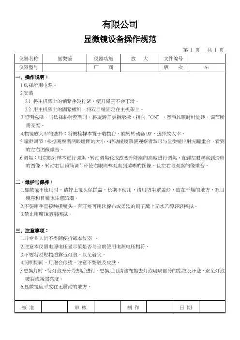
文件制修订记录1.0目的:为正确操作工具显微镜以达到精确测量之目的。
2.0范围:为工具显微镜操作使用。
3.0权责:品管部4.0操作步骤:4.1开机,按以下顺序。
4.1.1墙壁上总开关使指示灯亮。
4.1.2按下稳压器NO一端,观察稳压器指针是否有指220V。
4.1.3显微镜上绿色开关。
4.1.4显微镜上两黑色开关。
4.2调试:4.2.1转动左右轴或前后轴,使镜头对准镜头中间。
4.2.2将产品放置于工作台镜片中央。
4.2.3调焦距,旋转立柜手轮进行调焦距,至在目视镜上能看清晰物品。
4.3测试平面:4.3.1转动左右或上下轴,使物品一平面与基准线重合,将物品所测基准点/线与基准线重合,后将数显器ON/OFF打开,按in/mm转化为mm,红色键为归零,然后水平/垂直方向旋转工作台,使物品另一点/线与所找显微镜基准线完全重合。
4.3.2读数测量:所转动轴的数显器上所示数据即为实测数据。
4.4度数测量:4.4.1转动左右或上下轴使物品一平面与基准线重合,取角度焦点将物品所量基准线与基准线重合,拧松右上螺丝,(右下螺丝不许动,为调试精度用)左手转动齿轮,使物品另一线所找显微基准完全重合。
4.4.2读数:齿轮顺着转动以基准0度指示度数所测实际宽数,齿轮逆转动360度一基准0度指示度数=所测实际度数。
4.5关机:按以下顺序4.5.1显微镜上两黑色开关。
4.5.2显微镜上两黑色开关。
4.5.3按下稳压器开关OFF一端。
4.5.4墙壁上总开关使指示灯灭。
5.0注意事项:5.1工作台玻璃上保护膜,测零件修毛刺,擦试干净,以免划花保护膜。
5.2注意产品接角玻璃轻拿轻放。
5.3严禁用脏布、手擦载物镜片、显微镜片。
5.4操作者的手必须干净,测量后物品一并带走,随时保持显微镜与桌面的卫生。
工时(秒)
版本发布日期B
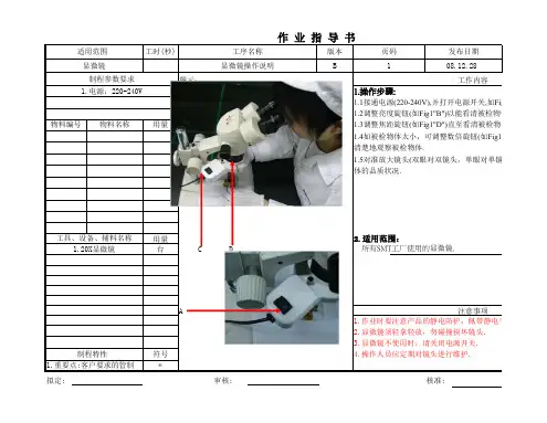
08.12.28 图示:
1.操作步骤:
1.1接通电源(220-240V),并打开电源开关,如Fig11"A".1.2调整亮度旋钮(如Fig1"B")以能看清被检物体为宜.物料编号用量
1.3调整焦距旋钮(如Fig1"D")直至看清被检物体.
1.4如被检物体太小,可调整数倍旋钮(如Fig1.C)至20倍,以清楚地观察被检物体.1.5对准放大镜头(双眼对双镜头,单眼对单镜头),仔细观察
体的品质状况.
用量 2.适用范围:
台
C
D
所有SMT工厂使用的显微镜.A
符号*
1.重要点:客户要求的管制点
拟定:
审核:
核准:
2.显微镜须轻拿轻放,勿碰撞损坏镜头.
3.显微镜不使用时,请关闭电源开关.制程特性
4.操作人员应定期对镜头进行维护.
注意事项
1.作业时要注意产品的静电防护,佩带静电手套 工具、设备、辅料名称
1.20X显微镜
制程参数要求工作内容
1.电源:220-240V
物料名称适用范围 工序名称页码显微镜显微镜操作说明
1
文件编号
KT-M-030
接通电源(220-240V),并打开电源开关,如Fig11"A".
调整亮度旋钮(如Fig1"B")以能看清被检物体为宜.
调整焦距旋钮(如Fig1"D")直至看清被检物体.
如被检物体太小,可调整数倍旋钮(如Fig1.C)至20倍,以便于更对准放大镜头(双眼对双镜头,单眼对单镜头),仔细观察被检物
电手套和静电环.。
显微镜使用说明书认识显微镜:(1)各结构名称(见书本54页)(2)物镜与目镜中的10*代表放大10倍40*代表放大40倍(3)显微镜放大倍数=目镜放大倍数*物镜放大倍数显微镜的使用:1.右手握镜臂,左手托底座,将显微镜放在水平桌面上,镜筒在前,镜臂在后,放于身体坐前方。
2.依次将目镜与物镜装好。
(装物镜时左手食指与中指夹住物镜,右手旋转,低倍与高倍各装一个)3.转动转换器,让低倍物镜对牢通光孔,转动集光器,使用大光圈,然后左眼看目镜,右手转动反光镜,直到看一个明亮的视野。
(光线不足时用凹面镜,光线充足时用平面反光镜)4.将所需观察的物体或装片放在载物台上,正对通光孔,用压片夹夹住。
5.两手向外(顺时针)转动粗准焦螺旋,将镜筒下降,从旁观看物镜,以免物镜压破装片或物体损坏镜头6.左眼对牢目镜,两手慢慢地向内(逆时针)转动粗准焦螺旋,直到观察到物像,若不够清晰,再调节细准焦螺旋。
若放大倍数不够则进行如下操作:(1)将观察物移到视野的中央(2)转动物镜让高倍物镜对牢通光孔(3)调节细准焦螺旋,直到物象清晰。
(在此过程中不能转动粗准焦螺旋)显微镜使用说明书认识显微镜:(1)各结构名称(见书本54页)(2)物镜与目镜中的10*代表放大10倍40*代表放大40倍(3)显微镜放大倍数=目镜放大倍数*物镜放大倍数显微镜的使用:1右手握镜臂,左手托底座,将显微镜放在水平桌面上,镜筒在前,镜臂在后,放于身体坐前方。
2.依次将目镜与物镜装好。
(装物镜时左手食指与中指夹住物镜,右手旋转,低倍与高倍各装一个)3.转动转换器,让低倍物镜对牢通光孔,转动集光器,使用大光圈,然后左眼看目镜,右手转动反光镜,直到看一个明亮的视野。
(光线不足时用凹面镜,光线充足时用平面反光镜)4.将所需观察的物体或装片放在载物台上,正对通光孔,用压片夹夹住。
5.两手向外(顺时针)转动粗准焦螺旋,将镜筒下降,从旁观看物镜,以免物镜压破装片或物体损坏镜头6.左眼对牢目镜,两手慢慢地向内(逆时针)转动粗准焦螺旋,直到观察到物像,若不够清晰,再调节细准焦螺旋。
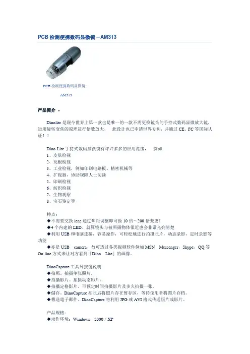
PCB检测便携数码显微镜-AM313PCB检测便携数码显微镜-AM313产品简介»Dinolite是现今世界上第一款也是唯一的一款不需更换镜头的手持式数码显微放大镜,运用旋转变焦的原理进行倍数放大,此设计也已申请世界专利,并通过CE、FC等国际认证!!Dino-Lite手持式数码显微镜有许许多多的应用范围,例如:1、皮肤检视2、发根检视3、工业检视,例如印刷电路板、精密机械等4、扩视器,协助视障人士阅读5、印刷检视6、纺织检视7、生物观察8、宝石鉴定等特点:◆不需要交换lens通过焦距调整即可做10倍~200倍变更!◆4个内建的LED、就算镜头与被照摄物体很近也会非常光亮清楚◆利用USB和电脑连接,容易操作,可轻松地进行拍摄照片,动态录影,定时录影等功能◆亦是USB camera、故可透过各类视频软件例如MSN Messenger,Skype,QQ等On-line方式来让对方看到「Dino Lite」的画像。
DinoCapture工具列按键说明◆拍照。
拍摄单张照片。
◆拍攝影片。
拍摄动态影片。
◆拍攝定格影片。
可预定时间拍摄影片及多久拍摄一张。
◆儲存。
DinoCapture拍照后将照片存在暂存区,等待使用者将图片存档。
◆傳送電子郵件。
DinoCapture将利用JPG或AVI格式传送照片或影片。
产品规格:◆动作环境:Windows2000/XP◆Interface:USB1.1(2.0)◆sensor:1/4CMOS◆解析度:VGA(640x480)◆倍率:10x~200x◆Light:内建LED Light◆frame rate:30fps◆使用可能范囲:3.2cm~10cm◆曝光补正:自动曝光/自动补正/自动Color balance彩度对比补正◆Size:90g◆软件带测量功能:可测量直线、连续线、半径圆、直径圆、三点圆、角度;可在拍摄图片之上任意颜色进行标注、进行绘图;测量单位可选择mm、um、mil(0.001inch)等等。
激光扫描共聚焦显微镜操作指南说明书[激光扫描共聚焦显微镜操作指南说明书]引言:本操作指南为用户提供激光扫描共聚焦显微镜的详细操作流程及相关注意事项。
在使用本设备之前,请仔细阅读本指南,以确保能够正确、安全地操作设备,并获得最佳的成像效果。
一、设备介绍激光扫描共聚焦显微镜是一种先进的显微镜技术,结合了共聚焦成像和激光扫描技术,可以实现高分辨率、三维成像及活细胞观察等功能。
本设备由以下主要部分组成:1. 共聚焦显微镜主体:包括光源系统、光学系统、扫描系统、探测器等核心部件。
请勿对主体进行任何未经授权的拆卸或修改。
2. 控制系统:用于控制设备的开关、成像参数设置、图像采集及处理等功能。
在操作设备之前,请确保控制系统处于正常工作状态。
二、准备工作在操作激光扫描共聚焦显微镜之前,请进行以下准备工作:1. 检查设备:确保设备的电源线、信号线、光纤等连接线路良好,无损坏或松动情况。
2. 准备标本:根据需要观察的样本类型,准备适当的标本片,并在标本片上施加适当的荧光染料。
3. 调整镜片:根据需要选择适当的镜头,并按照设备说明进行安装和调整。
三、操作步骤以下为基本的操作流程,具体步骤可能会因设备型号和厂家而有所不同,请根据实际情况进行操作:1. 打开设备电源:将电源开关置于“开启”位置,待设备启动完全后,检查设备各部分是否正常。
2. 设置成像参数:通过控制系统,设置激光波长、放大倍数、成像模式等参数。
根据标本类型及观察需求,合理选择参数设置。
3. 校准镜片:根据设备说明书,进行扫描头和标本之间的焦距调整,保证成像过程中的清晰度和准确度。
4. 开启激光:根据标本需要,选择相应的激光波长,并逐一打开相应激光。
5. 定位标本:通过显微镜目镜进行初步观察,调整位置和焦距,使标本位于成像区域。
6. 开始扫描成像:在控制系统中选择扫描图像模式,点击“开始扫描”按钮,启动扫描成像过程。
7. 图像采集和处理:根据需要,可设置图像采集的帧数、分辨率等参数,并在采集图像后进行必要的图像处理和分析。
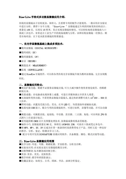
Dino-Lite手持式多功能显微镜应用介绍:传统的显微镜由于结构复杂,体积大,且需要专用的配件才能使用,一般应用在实验室中进行分析,携带十分不方便,“Dino-Lite ”显微镜通过专利的同轴变焦结构设计,重量仅100克,长度仅10厘米,真正实现显微镜轻便化、可以轻松地将显微镜放入口袋或工具包中,非常适合工业生产中的现场观测与分析,该种结构显微镜一经推出,颇受市场欢迎,以下是该款显微镜的简要描述。
一、在光学显微镜基础上集成多项技术:■数码显微镜(DIGITAL MICROSCOPE)■数码相机(DC)■数码摄像机(DV)■录音(RECORD)■测量技术(MEASUREMENT)■监视(SURVEILLANCE)■通过DinoEye目镜组件,可以将各类传统光学显微镜升级为数码显微镜,完全实现数码化。
二、显微镜应用特点:■视觉扩展功能:眼睛不必紧靠显微镜目镜,可大大减少操作使用者视觉疲劳,将眼睛解放出来。
■直接成像:在电脑或电视屏幕上成像, 可进行多媒体演示并供多人观看。
■无级旋转变焦功能:不需更换显微镜目镜镜头,通过焦距调整可放大10~200 ;500放大倍率。
■照明功能:内置高亮度白色、荧光、红外LED灯、勿需借助外部辅助光源。
■连接电脑USB接口,配合专用的显微镜软件,可进行拍照, 录像等功能,并可自动储存。
■测量功能:可测量直线、连续线、半径圆、直径圆、三点圆、角度;可在所拍JPG格式图片上任意进行标注。
■采用超清晰CMOS芯片及图像处理技术,显微镜成像效果晶莹剔透。
■袖珍小巧,显微镜重量仅90克, 体积仅10CM*D3.2CM,可放在口袋或笔记本包中。
■继MP3、MP4、DC、DV后成为年青一族新的时尚消费类电子产品,同时又是一种良好的教学、分析、鉴定、检测及学习工具。
■ 配合专用开发的DINOCAPTURE显微应用软件,具备测量、测绘、模式识别等功能。
三、Dino-Lite显微镜应用范围■医学分析:耳道、耳膜、眼睛虹膜、牙齿检查、分析及诊断。
荧光显微镜操作手册Olympus BX51物镜: 4 ×0.16 (无DIC)10×0.4020×0.7540×1.00 oil100×1.40 oil荧光滤色块转盘: 1. WU 蓝2. WIB 绿(长通)3. WIBA 绿(带通)4. WIG 红5. CFP 青6. YFP 黄操作步骤:(注意:样品须在低倍镜下放置和取下)DIC观察:1.打开明场电源开关(“︱”为开,“○”为关)2.将样品置于载物台上,用样品夹夹好3.将起偏器、检偏器、DIC棱镜推入光路,荧光滤块转盘拨到“1”位置,DIC棱镜应与相应的物镜倍数相匹配4.先选用低倍物镜(“10×”)5.调节透射光的强度,调节焦距,找到视野6.换到高倍镜头,观察样品7.DIC观察时,光路选择拉杆拉到中间位置,既可观察,也可拍照荧光观察:1.打开明场电源开关2.打开汞灯电源开关3.将样品置于载物台上,用样品夹夹好4.检偏器、DIC棱镜在光路外5.将荧光光路shutter打开(“○”为开,“●”为关),需保护样品时关闭shutter6.光路选择拉杆推至最里边7.根据样品的标记情况将荧光滤块转盘转到相应的位置8.通过两组减光滤片调节激发光强度9.从低倍镜开始观察,调焦,找到预观察视野,10.依次换到高倍镜头,观察样品11.拍照时光路选择拉杆完全拉出普通明场观察:1.打开明场电源开关(“︱”为开,“○”为关)2.将样品置于载物台上,用样品夹夹好3.起偏器、检偏器、DIC棱镜在光路外,荧光滤块转盘拨到“1”位置,DIC棱镜拨到明场(BF)位置4.先选用低倍物镜(“4×”)5.调节透射光的强度,调节焦距,找到视野6.依次换到高倍镜头,观察样品7.光路选择拉杆拉到中间位置既可观察,也可拍照关机:1.关闭汞灯电源(注意:汞灯需使用半小时以上方可关闭,关闭半小时以后方可再次开启)2.将透射光调到最小,关闭明场电源开关3.将镜头转到低倍镜,取出样品,若使用过油镜用干净的擦镜纸擦拭镜头4.确认数据已经保存,关闭软件5.使用光盘拷贝数据(禁止使用移动储存设备拷贝数据)6.关闭电脑,登记使用时间、荧光数字等使用情况Olympus IX71物镜:物镜倍数相差环4 ×0.13 PHL10×0.30 PH1 20×0.45 PH1 40×0.60 PH2 60×1.35 oil (无相差)荧光滤色块转盘: 1. WU 蓝2. WIB 绿(长通)3. WIBA 绿(带通)4. WIGA 红5. CFP6. YFP操作步骤:相差观察:1.打开明场电源开关(“︱”为开,“○”为关)2.将样品置于载物台上3.将光路选择旋钮调至观察位置4.从低倍镜开始观察,调节到与镜头相匹配的相差环,荧光滤块转盘拨到“1”的位置5.调节透射光光强,调节焦距,找到预观察视野6.依次换到高倍镜,(注意调节相差环)观察样品7.拍照时将光路选择旋钮调至相机位置荧光观察:1.打开明场电源开关2.打开汞灯开关3.将样品置于载物台上4.将荧光光路shutter打开(“○”为开,“●”为关),需保护样品时关闭shutter5.将光路选择旋钮调至观察位置6.根据样品的标记情况将荧光滤块转盘转到相应的位置7.通过两组减光滤片调节激发光强度8.从低倍镜开始观察,调焦,找到预观察视野,9.依次换到高倍镜头,观察样品10.拍照时将光路选择旋钮调至相机位置普通明场观察:1.打开明场电源开关(“︱”为开,“○”为关)2.将样品置于载物台上3.将光路选择旋钮调至观察位置4.从低倍镜开始观察,相差环拨到明场(BF)位置,荧光滤色块转盘拨到“1”的位置5.调节透射光光强,调焦,找到预观察视野6.依次换到高倍镜,观察样品7.拍照时将光路选择旋钮调至相机位置关机:1. 关闭汞灯电源(注意:汞灯需使用半小时以上方可关闭,关闭半小时以后方可再次开启)2. 将透射光强调到最小,透射光选择按钮按出3. 关闭明场电源开关4. 将镜头转到低倍镜,取出样品,若使用过油镜用干净的擦镜纸擦拭镜头5. 确认数据已经保存,关闭软件6. 使用光盘拷贝数据(禁止使用移动储存设备拷贝数据)7. 关闭电脑,登记使用时间、荧光数字等使用情况Olympus SZX16物镜:1×变倍:0.7~11.5荧光滤色块转盘:UV 蓝GFPHQ 绿RFP2 红操作步骤:明场观察:1.将样品置于载物台上2.推入光路选择拉杆,荧光滤块转盘拨到空位3.选择合适的光源⑴冷光源观察使用不透明的底板(黑或白),打开环形光电源开关(“︱”为开,“○”为关),调节光强度,找到预观察视野,调节变倍比,观察样品⑵底光源观察使用透明玻璃底板,打开底座电源开关(“︱”为开,“○”为关),将LBD滤片推入光路,调节反光镜方向、对比度和光强度,找到预观察视野,调节变倍比,观察样品4.拍照时将光路选择拉杆拉出荧光观察:1.将样品置于载物台上2.一般选择黑色不透明底板3.打开汞灯电源开关4.荧光光路挡板推出5.根据样品的标记情况将荧光滤块转盘转到相应的位置6.找到预观察视野,调节变倍比7.观察样品8.拍照时将光路选择拉杆拉出关机:1.关闭汞灯电源(注意:汞灯需使用半小时以上方可关闭,关闭半小时以后方可再次开启)2.将明场光强调到最小,关闭明场电源开关3.取出样品,将变倍比调到最小4.确认数据已经保存,关闭软件5.使用光盘拷贝数据(禁止使用移动储存设备拷贝数据)6.关闭电脑,登记使用时间、荧光数字等使用情况软件应用1.双击打开DP Controller软件2.点击预览键,选择image size(一般1360 X 1024)、objective、ISO sensitivity(明场拍照选择ISO200,荧光拍照选择ISO400)、exposure mode(一般选择manual),调节exposure time3.调节黑/白平衡(明场拍照用白平衡,荧光拍照用黑平衡)。
Dino Capture 迪光数码显微镜使用手册目录第一章:文件夹使用功能1.1 新建 (1)1.2 打开 (1)1.3 文件夹属性 (1)1.4 退出程序 (1)第二章:使用文件功能2.1 打开 (2)2.2 复制 (2)2.3 另存新档 (2)2.4 删除 (2)2.5 传送邮件 (2)2.6 打印 (2)2.7 关闭所有已开启文件 (2)第三章:Dino-Lite 设定3.1 显示影像列表 (3)3.2 显示工具窗口 (3)3.3 显示状态列表 (3)3.4 显示测量属性 (3)3.5 显示十字线 (3)3.6 语言设置 (3)3.7 音效.................. (3)3.8 自动更新............. .. (3)第四章:帮助4.1 使用说明 (4)4.2 关于软件 (4)4.2 许可协议 (4)第五章:工具按钮使用说明5.1 画图工具 (5)5.1.1文本 (5)5.1.2直线 (6)5.1.3箭头 (6)5.1.4任意线 (7)5.1.5矩形 (7)5.1.6椭圆 (8)5.2 测量工具 (9)5.2.1直线测量 (9)5.2.2连续线测量 (9)5.2.3点到线测量 (10)5.2.4多边形测量 (11)5.2.5半径圆测量 (11)5.2.6直径圆测量 (12)5.2.7三点圆测量 (12)5.2.8三点弧度测量 (13)5.2.9三点角度测量 (13)5.2.10四点角度测量 (14)5.2.11中心距离测量 (14)5.2.12圆格 (15)5.2.13十字线 (15)5.2.14网格线 (16)第六章:文本和线条编辑6.1 线条颜色 (17)6.2 线条类型 (17)6.3 线条宽度 (17)6.4 字体设置 (18)第七章:测量属性7.1 测量属性窗口 (19)7.1 放大按钮 (19)第八章:测量工具8.1 测量工具 (20)8.2 放大倍率 (20)8.3 单元 (20)第九章:测量校正功能 (21)第十章:辅助说明 (25)第一章:文件夹使用功能文件夹1.1 新建“新建文件夹”选项,允许您创建一个新的文件夹保存照片影像或者照片档案:如果没有文件创建,“新建文件夹”选项将会显示灰色,自动失效。
显微镜使用说明1,显微镜开关时卤素灯电压一般应调至最低。
2,转换物镜时,应旋转物镜架,不要用手直接转物镜。
3,荧光光源汞灯由于使用寿命短,为保证尽可能的延长使用时间和安全,汞灯电源开/关间隔时间必须大于三十分钟。
4,显微镜的各光学部件应调节到位(如,DIC 插件,荧光滤片,物镜等),以免影响显微镜的正常工作。
如果不到位,那么观察时通常会看到月牙形阴影.5,使用油镜时应使用专业用油,不要用其它介质(如香柏油),以免损伤镜头。
每次使用完油镜后,需将油镜擦拭干净(物镜及玻片)。
(正置显微镜,油滴在样品上。
倒置显微镜,油直接滴在物镜上。
)6,不要用手直接触摸光学部件的表面(如物镜,荧光模块,目镜等),以免留下手指印在上面,影响观察效果。
7,在拆卸全自动显微镜的聚光镜,荧光滤片盒(倒置显微镜)等部件时,应在断电的情况下进行操作。
8,因为各款显微镜的有效工作距离/特性等各有不同,使用前应充分了解所用仪器的特性及观测范围,以免因不恰当的操作,对显微镜及其配件造成损害。
提示:1,观测样品时(特别是金相样品),切不可将物镜撞及样品,以免将物镜镜头压碎。
2,移动显微镜时,应做到小心轻放,以免因震动而对光学部件及光路造成损害,影响显微镜的使用。
(建议移动显微镜时,先将各光学部件拆除,移位后,再重新安装。
)二一般观察方式的调节为了观察和拍摄好图像,需要对显微镜和CCD以及CCD软件都要求进行调节。
在进行显微观察和摄影前,首先要做的就是对显微镜进行调节。
调节项目包括柯勒照明、相差环调节、荧光中心调节等。
其中后两项一般在安装是已经调节好,以后一般情况下就不需要再调节了。
柯勒照明调节方法如下:1,放一张你即将观察的样本,使用明场照明状态(聚光镜转轮选择 H 或 BF,荧,光滤镜轮选择空位,DIC 附件全部拉出光路,照相光路转换到观察状态)10X 物镜,通过粗调和微调将其调节到样本能观察到的最清楚的状态。
然后不要再动调焦螺旋。
English 1Dino-Lite User manualENGLISHThank you for purchasing a Dino-Lite microscope. The DinoCapture software is designed to give you the best possible digital microscopy experience by the inventors of the handheld digital microscope. The DinoCapture software runs on computers with a Windows XP , Windows Vista or Windows 7/8 operating system. The DinoXcope software is designed to work with Apple Macintosh OS.Important safety information• Avoid touching the lens with finger to protect theproduct from electrostatic damage• Do not drop• Keep dryIndexSoftware installation2Software interface DinoCapture / Windows4Software interface DinoXcope / Mac11Cleaning and maintenance, warranty, support122 English Dino-Lite User manualSoftware installationThe DinoCapture and DinoXcope software is licensed from Anmo Electronics Corporation and is subject to an End User License Agreement (EULA) that users will have to accept during theinstallation process.Important notice: DO NOT connect the USB cable of the Dino-Lite to the PC before installing the software.1. Use the CD delivered with your Dino-Lite to install theDinoCapture and DinoXcope software and drivers. Alternatively, download and run the latest version of the software from the support section of the website: www.dino-lite.eu .2. Click ‘Next’ and the Installshield wizard will start. (An ‘OpenFile-security warning’ may appear on some systems.Select ‘Run’ or ‘YES’). Choose the language you want for the DinoCapture 2.0 interface.3. Read the User License Agreement. If you agree, press ‘Yes’ tocontinue or press ‘no’ to stop the installation.4. Select a destination folder for the DinoCapture software. Whendone, press ‘Next’. Click ‘Install’ to start installing the software. If the Windows security warning message appears, click ‘Install this driver software anyway’.5. When the installation is complete, selecting ‘Finish’ completesthe software installation.6. The DinoCapture software has an auto-update feature that willcheck for software updates when you start DinoCapture.7. A full manual can be found in the help function of DinoCapture,as a pdf on the CD or on the website.Hardware installation1. After full installation of the DinoCapture software and driverpackage, connect the Dino-Lite to one of the USB ports of your computer.Dino-Lite User manual 2. Please use a USB 2.0 port that is fully powered. Some USB portson portable computers do not supply sufficient power.3. The driver will be automatically installed. Please WAIT untilthe notification appears: ‘Device driver software installedsuccessfully’.4. Now start DinoCapture 2.0 by double clicking on the desktop icon.5. The LED lights should go on and an image should appear inDinoCapture. If this is not the case, refer to the frequently-asked-questions (FAQ) on www.dino-lite.eu.Hardware features1. At the center of the device, the adjustable dial is used toset the focus. The focus of the image depends on the distance to the object. Once you have focused on the object, you canread the magnification rate achieved from the number next to ƚŚĞ ȴ ƐLJŵďŽů͘2. The models in the AM/AD 411X series feature a magnificationlock. The magnification lock is particularly useful for repetitive inspection at a given level of magnification.3. Dino-Lite models with the letter T in their product name havea Microtouch function at the cable end of the device. Touchingthis sensor will capture the current image or start/stop videorecording (for usb-devices). On the Dino-Lite high speed realtime models the Microtouch sensor can be used to switch the LEDs on/off (all models) or freeze the image (AM5116 models only).4. Models with the letter Z in their product name have apolarization function, that can be controlled by turning theadjustable cap.5. Models with the letter L operate at a longer working distance.These models only achieve focus at some distance from theobject.6. The AD and Edge models have exchangeable front covers/caps. Align the red lines on cap and frontend of the Dino-Lite toEnglish 3Dino-Lite User manualremove or place the cap, then turn the cap 180 degrees. Some caps are designed to be clicked onto the microscope. In thiscase, there is no red line on the cap.7. The DinoEye models are designed as a replacement of theexisting ocular of a traditional microscope. The U model isintended to be placed over an existing ocular and the C model is intended to be connected to a C-mount adapter on a suitable microscope or optical device.8. Models with the letters TW have the macro zoom function. Software interface DinoCapture / WindowsThere are five key sections in the DinoCapture software:1. Menu bar2. Image list tools3. Preview window management bar4. Tool bar5. Preview window toolsMenu barFolder – create folders or access existing folders. Files – manage files, such as open, copy, save, print ordelete as well as send as e-mail or create slide show.Settings – customize the way the software operatessuch as:• Showing or hiding elements on the screen• The properties for measurements• T he way the Microtouch or foot pedal(if attached) work• A ccessing the Motorized focus accessorysettings• Connecting over IP• Bar code recognition function• ExternalGPS• Auto update function4 EnglishDino-Lite User manual Help – access the full user guide on screen, or readDinoCapture 2.0 information or the license agreement.Image list toolsOpen – open a picture selected from the imagethumbnail gallery below the image list tool bar.Copy – copy a selected picture to the windowsclipboard.Save as – save selected picture(s) to the desired fileformat or folder.E-mail – attach the selected picture(s) to a newmessage opened in your default e-mail client.Print – print the selected picture.Slideshow – run a slideshow of the selected pictures.Delete – clean up the image thumbnail gallery bydeleting the selected picture(s).Preview window management barThis window enables you to switch between windows if two or more Dino-Lite’s are connected at the same time or multiplepictures are opened.Tool barThe tool bar is divided into four parts:Draw tools – The draw tool set allows you to write text and draw on the images. The bar is located below the preview windowEnglish 56 English Dino-Lite User manualmanagement bar.Measurement tools – Many different measurement types can be done with the measurement tools. The double flash icon gives youaccess to the grid and ruler settings.Notice: The measurement and calibration feature is only available for certain models. For the DinoEye models, it isrecommended to make calibrated measurements only. Pleasecontact a local sales representative for further information.LineLeft click and drag to the desired length, and click again to finish.ContinuouslineClick and drag to form one section of distance, click again to start another section. Continue until the total desired distance is measured. Double click to finish.Point to lineCreate a line to represent the base by clicking once to start, drag, and then click again to set the endpoint. Branch off from the base line to start measuring the line that is 90 degrees from the base line and a final click to finish the measurement.PolygonClick and drag to form the desired length, and click again to start the next section. When finished, double click to finish the polygon measurement.Radius circleClick and extend out to the desired radius.Dino-Lite User manual Diameter Click and extend out to the desired diameter.Three point circle Click on any three points on the circle you wish to measure.Three point arc Click on three consecutive points on an arc to measure.Three point angle Start at the pivot point and extend out to start measuring an angle.Four points angle Select two points from one line segment and another two points from another line segment to complete the angle measurement.Center distance After drawing at least two circles, select the icon and the mouse pointer will change to a pointing finger for selectable circles. Click on each circle and the software will measure the distance.Gridlines The pitch will match the magnification inputted. Circle grid The pitch will match the magnification inputted.Crosshair on camera The crosshair XY position can be moved when you select it. The cursor position is the location of the mouse pointer and location 0,0 is the center coordinates of the crosshair.Scale crosshair The scale crosshair increments can be compared to the scale on the bottom left corner. The centre of the crosshair can be moved. (Magnification value needs to be entered for this feature to work).Text and line toolsLine format Select line color, style and widthFont Select font, font style, size and colorEnglish 7Dino-Lite User manualMeasurement optionsMeasure m ent properties Organize and show the status of all the measurements as well as the ability to adjust how the results are shown on the image.Magnifier Digitally enlarge the area around yourmouse pointer for more details and accuratemeasurements.Magnifi c ation Input the magnification in the blue box. Themagnification can be read from the dial on themicroscope.Units Select the unit of measurement, inch, mil, mm orum.Calibration menu Select calibration, create new calibration profile or open the calibration folder.Barcode Reader Click on the icon to enable and disable barcodedetection.Preview window toolsMicrotouch - This is activated when you touchthe Microtouch sensor. Activate or deactivate theMicrotouch. Some Dino-Lite models do not havethis feature.Auto Exposure – This allows you to change theexposure or turn off auto exposure. Sliding the barto the right increases the exposure time and viceversa.8 EnglishDino-Lite User manualWhite Balance - Select the required White Balance Mode (available on certain models only)LED control - Lets you turn ON/OFF or switch LED’s on the Dino-Lite (most models).Setting - The setting window allows you to control the camera settings.Maximize - Lets you see the live video or picture in full screen. To exit full screen mode, click anywhere on the screen or press “ESC”.Close window - Allows you to close the current windowSnapshot - Take a picture.Video recorder - Start/stop recording of a videoTime-Lapsed Video - Create a series of images orvideos taken at a regular time interval.EDR - Save a picture using Extended Dynamic Range(EDR)EDOF - Save a picture using EDOF (Extended Depth of Field)Choose the resolution for the image. Please note that an additional Codec may be required to display 5 megapixel resolution. See the support section onwww.dino-lite.eu for further information.Choose the folder where images/videos will be storedEnglish 9Dino-Lite User manualClick on the grey bar on the bottom of the previewwindow and the annotation box will expand. Writetext within this box and press ENTER to start anew line. When done, left click anywhere in thepreview window to save the annotation and exitthe annotation box.Focus strength indicator - Indicates the level offocus achieved (available on certain models only)10 EnglishDino-Lite User manual Software interface DinoXcope / MacThere are four main sections in the DinoXcope program window: bar1. Actionthe input magnification that you read from the focus dial.• Make video. Choose frame rate, recording time, quality and compression. To stop recording manually, use the ESC key • Make time lapse video. Choose capture interval, number of frames and playback frame rate, as well as quality andcompression.• Switch LED’s on/off• Go to full screen mode, to end full screen mode use the ESC keylist2. Image• Look at an image with mouse-over, or double-click to open in new windowEnglish 11Dino-Lite User manual3. Live image• Use the action bar for the action that you want to perform • Use the Controls menu (the menu bar is on top of the screen) to change settings, use (digital) zoom, freeze theimage, change the resolution or change the functioning ofthe Microtouch button.• Use the Live measurement function (in the Tools menu) to open a special selection window for drawing andmeasurement tools. After selection, click okay and use thetool on the live image.image4. Openmeasurement tools.Cleaning and maintenanceAvoid touching the lens with any substance. Clean the lens periodically with compressed air. Clean the body of the microscope regularly with a soft cloth dampened with disinfectant. Clean the detachable caps with a 50%-70% alcohol solution, do not use diethyl ether, 100% alcohol or alcohol gel.12 EnglishEnglish 13Dino-Lite User manualWarrantyThe DinoCapture software is provided for use with a Dino-Lite digital microscope supplied by AnMo Electronics or one of its distributors or resellers. The use of the DinoCapture software is guided by the End User License Agreement.The Dino-Lite product is delivered with a two year warrantyfrom the date of purchase by the end customer. Please note that accessories (i.e. detachable caps/extensions) are not covered under warranty. For warranty issues please contact the reseller or store where you bought the product.SupportIf you have any problem or issue with your Dino-Lite or the DinoCapture software, please contact your reseller or check the Dino-Lite Europe support pages at www.dino-lite.eu . An extensive user manual for DinoCapture can be found within the software and on the website.IDCP BV/Dino-Lite EuropeEnergiestraat 23-A, 1411 AR NaardenThe NetherlandsTel: +31206186322Fax: +31 20 6189692E-mail: *****************Web:www.dino-lite.euDino-Lite User manual2015Q1 © AnMo/IDCP/Dino-Lite Europe.No part of this publication may be reproduced or distributed unless for personal use in conjunction with usage of Dino-Lite digital microscopes.Patent info:US Pat. No. 7.102.817.B1Germany Pat. No. 20 2006 001 409.8Japan Pat. No. 3123176Taiwan Pat. No. M302031AnMo Electronics Corporation and its authorized representativein the EU, IDCP BV, declare that the apparatus Dino-Lite and DinoEye comply with the essential requirements and other relevant provisions of Directive 1999/5/EC. The original Declaration of Conformity can be found at www.dino-lite.eu/doc/dino-lite.pdf Version 2015Q1 Copyright14 English。