Calculated Absorption and Scattering Properties of Gold Nanoparticles of Different Size shape
- 格式:pdf
- 大小:341.67 KB
- 文档页数:11
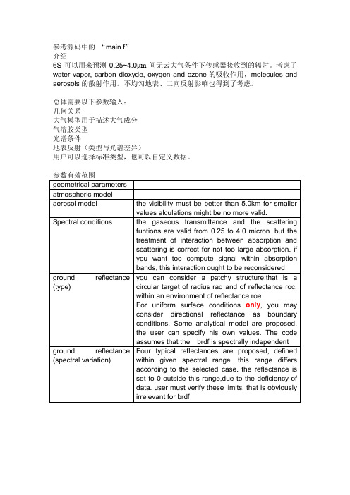
参考源码中的“main.f”介绍6S可以用来预测0.25~4.0μm间无云大气条件下传感器接收到的辐射。
考虑了water vapor, carbon dioxyde, oxygen and ozone的吸收作用,molecules and aerosols的散射作用。
不均匀地表、二向反射影响也得到了考虑。
总体需要以下参数输入:几何关系大气模型用于描述大气成分气溶胶类型光谱条件地表反射(类型与光谱差异)用户可以选择标准类型,也可以自定义数据。
1.输入几何条件igeom 取值0 , 1-70:用户输入太阳天顶角太阳方位角卫星天顶角卫星方位角月天以上参数按顺序用空格隔开1:meteosat observation用户需要再输入月天十进制的小时(universal time)列行(full scal 5000*2500)2:goes east observation用户需要再输入月天十进制的小时(universal time)列行(full scal 17000*12000)3:goes west observation用户需要再输入月天十进制的小时(universal time)列行(full scal 17000*12000)4:avhrr ( PM noaa )用户需要再输入月天十进制的小时(universal time)列(1-2048)xlonan hna5:avhrr ( AM noaa )用户需要再输入月天十进制的小时(universal time)列(1-2048)xlonan hnalong.(xlonan) and overpass hour (hna) at the ascendant node at equator xlonan 和hna 分别是卫星升交点与赤道的角度经度与时间6:hrv ( spot )用户需要再输入月天十进制的小时经度纬度7:tm ( landsat )用户需要再输入月天十进制的小时经度纬度2.输入大气模型idatm 取值0-80:no gaseous absorption 没有大气吸收1:tropical2:midlatitude summer3:midlatitude winter4:subarctic summer5:subarctic winter6:us standard 627:用户输入大气廓线radiosonde(无线探空仪)data on 34 levels,每一个level输入以下5个数据:enter altitude ( in km )pressure ( in mb )temperature ( in k )h2o density (in g/m3)o3 density (in g/m3)8:输入水汽含量和臭氧含量,大气廓线使用us62uw 单位g/cm2uo3 单位cm-atm3.输入气溶胶类型iaer 取值-1 , 0~3 , 5~7 , 4 , 8~9 , 11 , 12-1:user-defined profile先输入层数number of layers,在依次输入各层参数:高度(km),550nm光学厚度,气溶胶类型(下面的1-3,5-7)Example for iaer = -1:42.0 0.200 110.0 0.025 18.0 0.003 180.0 0.000 10:没有气溶胶1:大陆型2:海洋型3:城市5:沙漠background desert6:biomass burning7:平流层stratospheric4:define your own model using basic componentsc(1) = volumetric % of dust-likec(2) = volumetric % of water-solublec(3) = volumetric % of oceanicc(4) = volumetric % of soot 煤灰,烟灰between 0 to 1define your own model using a size distribution function8:Multimodal Log-Normal distribution (up to 4 modes)9:Modified Gamma distribution10:Junge Power-Law distributiondefine a model using sun-photometer measurements11:Sun Photometer distribution (50 values max)You have to enter:r and dV/d(logr)where r is the radius (in micron), V is the volume, and dV/d(logr) is in(cm3/cm2/micron). Then you have to enter: nr and ni for eachwavelength where nr and ni are respectively the real and theimaginary parts of the refractive indexor you can use the results computed and saved previously 12:Reading of data previously saved into FILEyou have to enter the identification name FILE in the next line of inputs. Note:For iaer=8,9,10,and 11:Results from the MIE subroutine may be saved into the file FILE.mie (Extinction and scattering coefficients, single scattering albedo, asymmetry parameter, phase function at predefined wavelengths) and then can be re-used with the option iaer=12, where FILE is an identification name youhave to enter.So, if you select iaer=8,9,10, or 11, you will have to enter iaerp after the inputs requested by options 8,9,10, or 11:iaerp=0 results will not be savediaerp=1 results will be saved into the file FILE.mie. Next line enterFILE.Example for iaer and iaerp8Multimodal Log-Normal distribution selected0.001 20 3Rmin, Rmax, 3 components0.471 2.512 0.17Rmean, Sigma, % density - 1st component1.53 1.53 1.53 1.53 1.53 1.53 1.53 1.53 1.53 1.53 1.53 1.53 1.5281.52 1.462 1.4 1.368 1.276 1.22 1.2 nr for 20 wavelengths 0.008 0.008 0.008 0.008 0.008 0.008 0.008 0.008 0.008 0.008 0.0080.008 0.008 0.008 0.008 0.008 0.008 0.008 0.0085 0.011ni0.0285 2.239 0.61Rmean, Sigma, % density - 2nd component1.53 1.53 1.53 1.53 1.53 1.53 1.53 1.53 1.53 1.53 1.53 1.53 1.5281.52 1.51 1.42 1.42 1.42 1.42 1.452 nr for 20 wavelengths 0.005 0.005 0.005 0.005 0.005 0.005 0.0053 0.006 0.006 0.0067 0.0070.007 0.0088 0.0109 0.0189 0.0218 0.0195 0.0675 0.046 0.004ni0.0118 2.0 0.22 Rmean, Sigma, % density - 3rd component1.75 1.75 1.75 1.75 1.75 1.75 1.75 1.75 1.75 1.75 1.75 1.75 1.751.75 1.77 1.791 1.796 1.808 1.815 1.9nr for 20 wavelengths 0.465 0.46 0.4588 0.4557 0.453 0.4512 0.447 0.44 0.436 0.435 0.4330.4306 0.43 0.433 0.4496 0.4629 0.472 0.488 0.5 0.57 ni 1Results will be saved into FILE.mieUrban_Indust Identification of the output file (FILE). results will be saved into Urban_Indust.mie4.输入气溶胶浓度v能见度,以km为单位。


学校代码 10459学号或申请号密级硕士学位论文论文题目作者姓名:张三导师姓名:李四教授学科门类:工科专业名称:培养院系:大电气、大物工完成时间:20xx年4月A thesissubmitted toZhengzhouUniversityfor the degree ofMasterThesis TitleBySan ZhangSupervisor: Prof. Si LiMajor NameInstitute NameApril20xx学位论文原创性声明本人郑重声明:所呈交的学位论文,是本人在导师的指导下,独立进行研究所取得的成果。
除文中已经注明引用的内容外,本论文不包含任何其他个人或集体已经发表或撰写过的科研成果。
对本文的研究作出重要贡献的个人和集体,均已在文中以明确方式标明。
本声明的法律责任由本人承担。
学位论文作者:日期:年月日学位论文使用授权声明本人在导师指导下完成的论文及相关的职务作品,知识产权归属郑州大学。
根据郑州大学有关保留、使用学位论文的规定,同意学校保留或向国家有关部门或机构送交论文的复印件和电子版,允许论文被查阅和借阅;本人授权郑州大学可以将本学位论文的全部或部分编入有关数据库进行检索,可以采用影印、缩印或者其他复制手段保存论文和汇编本学位论文。
本人离校后发表、使用学位论文或与该学位论文直接相关的学术论文或成果时,第一署名单位仍然为郑州大学。
保密论文在解密后应遵守此规定。
学位论文作者:日期:年月日摘要随着我国工业技术水平的快速发展与进步,对材料的质量的要求也越来越高。
在各个行业领域中,材料和器件中表面和亚表面的完整性会影响和决定系统和仪器设备的工作效率以及运行寿命。
此外,随着中国工业的高速发展,空气及水源污染问题也变得日益严峻。
环境污染导致了某些疾病的高发,皮肤病即是受环境因素诱导的典型疾病之一。
近年来,中国居民的皮肤病发病率逐年上升,且新增病例呈年轻化趋势。
因此实现对材料表面裂纹和皮肤表面病变的无损检测尤为重要。

laParticle size analysis-Laser diffraction methods(ISO-13320-1)IntroductionLaser diffraction methods are nowadays widely used for particle sizing in many different applications. The success of the technique is based on the tact that it can be applied to various kinds of particulate systems, is fast and can be automated and that a variety of commercial instruments is available. Nevertheless, the proper use of the instrument and the interpretation of the results require the necessary caution.Therefore, there is a need for establishing an international standard for particle size analysis by laser diffraction methods. Its purpose is to provide a methodology for adequate quality control in particle size analysis.Historically, the laser diffraction technique started by taking only scattering at small angles into consideration and, thus, has been known by the following names:-fraunhofer diffraction;-(near-) forward light scattering;-low-angle laser light scattering (LALLS).However, the technique has been broadened to include light scattering in a wider angular range and application of the Mie theory in addition to approximating theories such as Fraunhofer and anomalous diffraction.The laser diffraction technique is based on the phenomenon that particles scatter light in all directions with an intensity pattern that is dependent on particle size. All present instruments assume a spherical shape for the particle. Figure 1 illustrates the characteristics of single particle scattering patterns: alternation of high and low intensities, with patterns that extend for smaller particles to wider angles than for larger particles[2-7,10,15 in the bibliography].Within certain limits the scattering pattern of an ensemble of particles is identical to the sum of the individual scattering patterns of all particles present. By using an optical model to compute scattering for unit volumes of particles in selected size classes and a mathematical deconvolution procedure, a volumetric particle size distribution is calculated, the scattering pattern of which fits best with the measured pattern (see also annex A).A typical diffraction instrument consists of a light beam (usually a laser), a particulate dispersing device, a detector for measuring the scattering pattern and a computer for both control of the instrumentand calculation of the particle size distribution. Note that the laser diffraction technique cannot distinguish between scattering by single particles and scattering by clusters of primary particles forming an agglomerate or an aggregate. Usually, the resulting particle size for agglomerates is related to the cluster size, but sometimes the size of the primary particles is reflected in the particle size distribution as well. As most particulate samples contain agglomerates or aggregates and one is generally interested in the size distribution of the primary particles, the clusters are usually dispersed into primary particles before measurement.Historically, instruments only used scattering angles smaller than 14°,which limited the application to a lower size of about 1μm. The reason for this limitation is that smaller particles show most of their distinctive scattering at larger angles (see also annex Z).Many recent instruments allow measurement at larger scattering angles, some up to about 150°,for example through application of a converging beam, more or larger lenses, a second laser beam or more detectors. Thus smaller particles down to about μm can be sized. Some instruments incorporate additional information from scattering intensities and intensity differences at various wavelengths and polarization planes in order to improve the characterization of particle sizes in the submicrometre range.Particle size analysis – Laser diffraction methods-Part 1:General principles1 scopeThis part of ISO 13320 provides guidance on the measurement of size distributions of particles in any two-phase system, for example powders, sprays, aerosols, suspensions, emulsions and gas bubbles in liquids, through analysis of their angular light scattering patterns. It does not address the specific requirements of particle size measurement of specific products. This part of ISO13320 is applicable to particle sizes ranging from approximately μm to 3μm.For non-spherical particles, an equivalent-sphere size distribution is obtained because the technique uses the assumption of spherical particles in its optical model. The resulting particle size distribution may be different from those obtained by methods based on other physical principles . Sedimentation, sieving).3,terms, definitions and symbolsFor the purposes of this part of ISO 13320, the following terms, definitions and symbols apply.terms, definitionsabsorptionintroduction of intensity of a light beam traversing a medium through energy conversion in the mediumcoefficient of variation (变异系数)Noative measure(%) for precision: standard deviation divided by mean value of population and multiplied by 100 or normal distributions of data the median is equal to the meanrefractive index(Np)Refractive index of a particle, consisting of a real and an imaginary (absorption) part.Np=n p-ik prelative refractive index (m)complex refractive index of a particle, relative to that the medium。
Seismic 地震abnormal events:Coherent events which are not reflections. Refraction, reflected refractions, diffractions, surface waves, and sometimes multiple reflections are included (though there ' s nothing —abnormal II about any of these ).异常同相轴:相干非反射同相轴,包括折射波、反射折射波、绕射波、面波,往往也包括多次反射波(尽管这些波本身无任何异常) 。
absorption:A process whereby some of the energy of seismic wave is converted into heat while passing through a medium. Absorption for seismic waves is perhaps of the order of 1/2 db/cycle. Sometimes claimed to be proportional to the frequency squared rather than linear with frequency. See Q.吸收作用:为地震波通过某一介质时,其一部分能量转化为热量的一个过程。
地震波吸收衰减约为每周期1/2 分贝,有时表述为吸收与频率的平方成正比,而不是与频率成简单的线性正比关系。
见品质因数Q 。
acoustic: Sonic; pertaining to sound. Usually refers to compressional P waves, sometimes restricted to P-waves in fluids (liquids and gases ), sometimes generalized to include other elastic wave types.声学的,声的:声音的,声速的;属于声学范畴。
光学中光滑的英文Title: The Optical Phenomenon of Surface SmoothnessLight, a fundamental aspect of our physical world, has fascinated scientists and philosophers for centuries. One of the intriguing phenomena associated with light is the concept of surface smoothness and its optical implications. In the realm of optics, the smoothness of a surface plays a crucial role in the behavior of light as it interacts with various materials and surfaces.At the most basic level, the smoothness of a surface can be described as the absence of significant irregularities or deviations from a perfectly flat or uniform surface. When light encounters a smooth surface, it interacts with the surface in a predictable manner, exhibiting specific optical properties that are distinct from those observed when light interacts with a rough or uneven surface.One of the primary consequences of surface smoothness in optics is the phenomenon of specular reflection. Specular reflection occurs when light is reflected off a smooth surface in a manner where the angle of reflection is equal to the angle of incidence. This type of reflection is often observed in everyday life, such as the reflection of lightoff a mirror or a still body of water. The smoothness of the surface is a critical factor in determining the quality and clarity of the reflected image, as any irregularities or imperfections on the surface can distort or scatter the reflected light.In contrast, when light encounters a rough or uneven surface, the reflection of light is diffuse, meaning that the light is scattered in multiple directions rather than being reflected in a single, predictable direction. This diffuse reflection is responsible for the appearance of many everyday objects, such as matte painted surfaces or rough-texturedmaterials, where the light is scattered in a more random and unpredictable manner.The smoothness of a surface can also influence the refractive properties of light as it passes through the material. Refraction is the bending of light as it transitions from one medium to another, such as from air to glass or water. When light passes through a smooth surface, the refraction is consistent and predictable, allowing for the precise control and manipulation of light beams. This property is essential in the design and manufacture of optical components, such as lenses and prisms, where the smooth surfaces are crucial for achieving desired optical outcomes.Furthermore, the smoothness of a surface can also impact the transmission of light through the material. In the case of transparent materials, such as glass or certain plastics, the smoothness of the surfaces can minimize the scatteringand absorption of light, allowing for efficient transmission and the preservation of image quality. This is particularly important in the design of optical devices, such as camera lenses, where the quality of the transmitted light is crucial for capturing high-resolution images.The importance of surface smoothness extends beyond the realm of optics and has significant implications in various scientific and technological fields. In the field of materials science, the smoothness of a surface can influence the adhesive properties, friction, and wear characteristics of a material. Smooth surfaces can exhibit reduced friction and improved resistance to wear, making them valuable in applications such as mechanical engineering, tribology, and surface coatings.In the semiconductor industry, the smoothness of surfaces is critical for the fabrication of high-performanceelectronic devices. The manufacturing of integrated circuitsand microchips requires the creation of extremely smooth surfaces, often at the nanoscale level, to ensure the accurate deposition of thin films and the precise patterning of features. Any irregularities or roughness on the surface can lead to defects and performance issues in the final devices.Moreover, the smoothness of surfaces plays a crucial role in the development of advanced materials and technologies, such as in the field of nanotechnology. The ability to engineer and control surface smoothness at the nanoscalelevel has opened up new possibilities for the creation of novel materials with unique optical, electronic, and mechanical properties. These materials find applications in areas like quantum computing, energy storage, and medical diagnostics.In conclusion, the optical phenomenon of surface smoothness is a multifaceted and profoundly important aspectof the study of light and its interactions with various materials. The smooth or rough nature of a surface can significantly impact the behavior of light, influencing phenomena such as reflection, refraction, and transmission. The understanding and optimization of surface smoothness have far-reaching implications in a wide range of scientific and technological fields, from optics and materials science to semiconductor fabrication and nanotechnology. As our understanding of the optical properties of smooth surfaces continues to evolve, the potential for innovativeapplications and groundbreaking discoveries in these fields remains vast and exciting.。
Guide to Selecting Refractive Index Refractive index is a physical property of a material that can have a significant effect on light scattering particle size measurements. As such it is important to have an understanding of what refractive index is and how to make the correct selection for the material to be analyzed.IntroductionRefractive Index is defined by two components - real andimaginary:RI = n – i k, where:n = the real component, which is the ratio of the velocity of light in a vacuum to the velocity of light in the materialk = the extinction coefficient of the materiali = √ - 1The real component can be determined from published tables or it can be measured using Snell’s Law:n sin θ = n′θ sin ′, where:n = refractive index (RI) of first substance (usually air)θ = angle of incidencen′ = refractive index of secondsubstance (usually measured substance)θ′= angle of refraction (deviation from original directionFigure 1. RefractionThe imaginary component (k) of the refractive index is the extinction of the material, defined as the reduction of transmission of optical radiation caused by absorption and scattering of light k = (λ/4 π ) α, where:k = the extinction coefficientα = the absorption coefficientλ = the wavelength of light usedFigure 2. AbsorptionThe absorption coefficient (α) is the reciprocal of the distance light will penetrate the surface and be attenuated to 1/e of its original intensity, about 37%. Opaque materials will have a higher absorption coefficient than transparent materials.The effects of refractive index (RI) selection on reported particle size results are most pronounced when particles are spherical, particles are transparent, when the RI of the particle is close to the RI of the fluid, or when the particle size is close to the wavelength of the incident light.If particle characteristics deviate from any or all of these conditions, the refractive index value selected will have a smaller effect on the calculatedparticle size results.Calculating Relative Refractive IndexThe calculation of relative refractive index is includedto help users transition from older to more modern instruments. Modern HORIBA instruments do not require Relative Refractive Index. Users enter the refractive index of the medium (typically air or water) and the refractive index of the particle. This is simply the refractive index of the particle divided by the refractive index of the dispersion medium. If n = 1.33 (water) and n’ = 1.60 (particle), then the relative refractive index is 1.60/1.33 = 1.203.If the particles are totally transparent, then k = 0 and the selected kernel function would be 120-000. However, if the particles are somewhat opaque, then k > 0 and the selected kernel function would be 120-010.If the sample is being analyzed dry, then the relative index is as follows: If n = 1.0 (air) and n’ = 1.60 (particle), then the relative refractive index is 1.60/1.0 = 1.60. The selected kernel function would 160-000 or 160-020 depending on the degree of transparency of the particles.Practical Approach T o Selecting The Refractive Index (RI) ValuesThere are scores of RI values stored in the LA-seriesprograms. Values can be obtained from reference texts. In some cases, a single material may have several values of index of refraction depending upon its crystal structure. Alumina exists in alpha (a), beta (b), and gamma (g)crystalline forms. If the type is not known, use the average - the values usually are similar.The most difficult decision to be faced in selecting arefractive index value is that in which a mixture of materials is involved, each with a different RI value.If the particles are all roughly the same size, use a weighted average of the different RI values. If there is one component that is smaller in size, then it will bemore sensitive to changes in refractive index. It would be more important to use the correct value for this smaller component. In any case,any potential errors from differing refractive index materials should cancel each other out. There are situations in which a value for refractive index is not known and is not readily available. Remembering that RI compensation is much less important for non-spherical particles, the best approach is to use a default value. Choose a relatively large number such as 1.8 for the real index.In the case of truly spherical particles, it is important to determine an accepted value for RI unless the particles are very large. Large particles fall into the realm of Fraunhofer Diffraction and are affected less by refractive index.Important Variables to ConsiderOpaque particlesIf material is absorbing, it does not transmit light—such as a metal powder, carbon black, coke, coal or other similar material. If it is not transparent, a high imaginary component should be inserted.Non-spherical particlesIf the particles are not perfectly spherical, index correction is generally not critical. Very few industrial materials are truly spherical. Even latex particles made on earth are not absolutely spherical, but may be sufficiently so as to be considered spherical for index correction purposes. Unless an estimated 80% or greater amount of the sample is spherical, the sample should be considered non-spherical.Very large particlesMeasurement of particles that are larger than several microns is influenced very little by the refractive index of the material. Particles that are very largecompared to wavelength of light can be measured using Fraunhofer Diffraction which is the deflection of light at an edge. High, default real index and large imaginary component should be selected.Imaginary valueThe imaginary component is the Extinction Coefficient (k), which is a direct function of the absorption coefficient (α). If the particles are completely transparent, the value approaches zero (0). If they are opaque, the value can be very large. Corrections for the imaginary component are less critical for very large values of k.Effect on resultsHigher refractive index gives a higher angle of scatter for the same particle size. Changing to a higher refractive index for the same sample material would yield results showing an increased size; the instrument is getting a higher angle of scatter than it expects for that size of particle. Changing the imaginary component should not change the median size of the distribution significantly, but it will change the shape of the distribution. The maindifference will be observed when changing between 0.00 (transparent, spherical) and any other value.Using «chemistry» to estimate RI: Refractive index is the ratio of the velocity of light in a vacuum to the velocity of light in the material. This difference in speed is related to the interaction of the light wave with the electrons in the material. A material with a looser hold on its electrons will interact with the light wave more, giving a higher refractive index. This applies to electrons in a bond as well.ExamplesRI will increase as you proceed down or to the right in the periodic table. Use this to approximate RI from other known materials (SiO 2 - 1.46, GeO 2 - 1.65). In an organic molecule, the more functional groups, the higher the RI (Hexane 1.37, Bromohexane 1.45).*********************/scientificUSA: +1 (800) 446-7422 • France: +33 (0)1 64 54 13 00 • Japan: +81 (0)3 38618231T h i s d o c u m e n t i s n o t c o n t r a c t u a l l y b i n d i n g u n d e r a n y c i r c u m s t a n c e s - © H O R I B A I n s t r u m e n t s , I n c . 01/2018。