Verilog硬件描述语言cpu设计实例
- 格式:pdf
- 大小:622.67 KB
- 文档页数:65
verilog hdl语言100例详解Verilog HDL语言是一种硬件描述语言,用于描述数字电路和系统的行为和结构。
它是硬件设计工程师在数字电路设计中的重要工具。
本文将介绍100个例子,详细解释Verilog HDL语言的应用。
1. 基本门电路:Verilog HDL可以用于描述基本门电路,如与门、或门、非门等。
例如,下面是一个描述与门电路的Verilog HDL代码:```verilogmodule and_gate(input a, input b, output y);assign y = a & b;endmodule```2. 多路选择器:Verilog HDL也可以用于描述多路选择器。
例如,下面是一个描述2:1多路选择器的Verilog HDL代码:```verilogmodule mux_2to1(input a, input b, input sel, output y);assign y = sel ? b : a;endmodule```3. 寄存器:Verilog HDL可以用于描述寄存器。
例如,下面是一个描述8位寄存器的Verilog HDL代码:```verilogmodule register_8bit(input [7:0] d, input clk, input reset, output reg [7:0] q);always @(posedge clk or posedge reset)if (reset)q <= 0;elseq <= d;endmodule```4. 计数器:Verilog HDL可以用于描述计数器。
例如,下面是一个描述8位计数器的Verilog HDL代码:```verilogmodule counter_8bit(input clk, input reset, output reg [7:0] count);always @(posedge clk or posedge reset)if (reset)count <= 0;elsecount <= count + 1;endmodule```5. 加法器:Verilog HDL可以用于描述加法器。
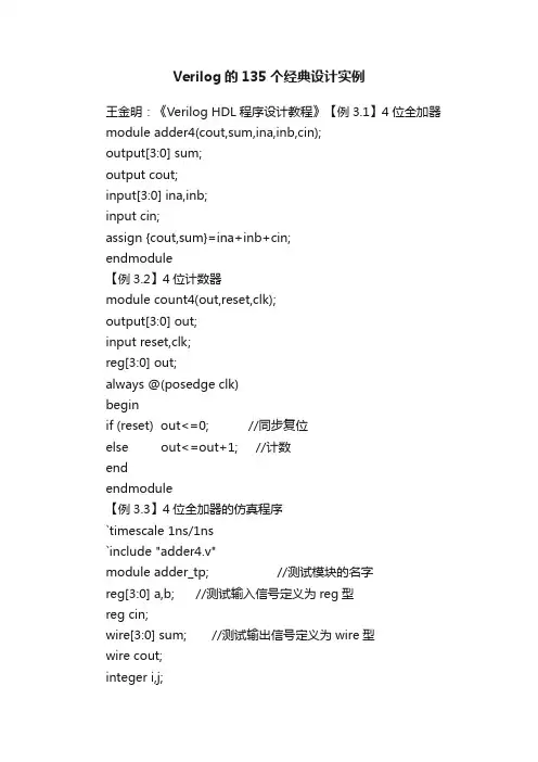
Verilog的135个经典设计实例王金明:《Verilog HDL程序设计教程》【例3.1】4位全加器module adder4(cout,sum,ina,inb,cin);output[3:0] sum;output cout;input[3:0] ina,inb;input cin;assign {cout,sum}=ina+inb+cin;endmodule【例3.2】4位计数器module count4(out,reset,clk);output[3:0] out;input reset,clk;reg[3:0] out;always @(posedge clk)beginif (reset) out<=0; //同步复位else out<=out+1; //计数endendmodule【例3.3】4位全加器的仿真程序`timescale 1ns/1ns`include "adder4.v"module adder_tp; //测试模块的名字reg[3:0] a,b; //测试输入信号定义为reg型reg cin;wire[3:0] sum; //测试输出信号定义为wire型wire cout;integer i,j;adder4 adder(sum,cout,a,b,cin); //调用测试对象always #5 cin=~cin; //设定cin的取值initialbegina=0;b=0;cin=0;for(i=1;i<16;i=i+1)#10 a=i; //设定a的取值end- 1 - 程序文本initialbeginfor(j=1;j<16;j=j+1)#10 b=j; //设定b的取值endinitial //定义结果显示格式begin$monitor($time,,,"%d + %d + %b={%b,%d}",a,b,cin,cout,sum);#160 $finish;endendmodule【例3.4】4位计数器的仿真程序`timescale 1ns/1ns`include "count4.v"module coun4_tp;reg clk,reset; //测试输入信号定义为reg型wire[3:0] out; //测试输出信号定义为wire型parameter DELY=100;count4 mycount(out,reset,clk); //调用测试对象always #(DELY/2) clk = ~clk; //产生时钟波形initialbegin //激励信号定义clk =0; reset=0;#DELY reset=1;#DELY reset=0;#(DELY*20) $finish;end//定义结果显示格式initial $monitor($time,,,"clk=%d reset=%d out=%d", clk, reset,out);endmodule【例3.5】“与-或-非”门电路module AOI(A,B,C,D,F); //模块名为AOI(端口列表A,B,C,D,F)input A,B,C,D; //模块的输入端口为A,B,C,Doutput F; //模块的输出端口为F- 2 -王金明:《Verilog HDL程序设计教程》wire A,B,C,D,F; //定义信号的数据类型assign F= ~((A&B)|(C&D)); //逻辑功能描述endmodule【例5.1】用case语句描述的4选1数据选择器module mux4_1(out,in0,in1,in2,in3,sel);output out;input in0,in1,in2,in3;input[1:0] sel;reg out;always @(in0 or in1 or in2 or in3 or sel) //敏感信号列表case(sel)2'b00: out=in0;2'b01: out=in1;2'b10: out=in2;2'b11: out=in3;default: out=2'bx;endcaseendmodule【例5.2】同步置数、同步清零的计数器module count(out,data,load,reset,clk);output[7:0] out;input[7:0] data;input load,clk,reset;reg[7:0] out;always @(posedge clk) //clk上升沿触发beginif (!reset) out = 8'h00; //同步清0,低电平有效else if (load) out = data; //同步预置else out = out + 1; //计数endendmodule【例5.3】用always过程语句描述的简单算术逻辑单元`define add 3'd0`define minus 3'd1`define band 3'd2`define bor 3'd3`define bnot 3'd4- 3 - 程序文本module alu(out,opcode,a,b);output[7:0] out;reg[7:0] out;input[2:0] opcode; //操作码input[7:0] a,b; //操作数always@(opcode or a or b) //电平敏感的always块begincase(opcode)`add: out = a+b; //加操作`minus: out = a-b; //减操作`band: out = a&b; //求与`bor: out = a|b; //求或`bnot: out=~a; //求反default: out=8'hx; //未收到指令时,输出任意态endcaseendendmodule【例5.4】用initial过程语句对测试变量A、B、C赋值`timescale 1ns/1nsmodule test;reg A,B,C;initialbeginA = 0;B = 1;C = 0;#50 A = 1; B = 0;#50 A = 0; C = 1;#50 B = 1;#50 B = 0; C = 0;#50 $finish ;endendmodule【例5.5】用begin-end串行块产生信号波形`timescale 10ns/1nsmodule wave1;reg wave;parameter cycle=10;initialbegin- 4 -王金明:《Verilog HDL程序设计教程》wave=0;#(cycle/2) wave=1;#(cycle/2) wave=0;#(cycle/2) wave=1;#(cycle/2) wave=0;#(cycle/2) wave=1;#(cycle/2) $finish ;endinitial $monitor($time,,,"wave=%b",wave); endmodule【例5.6】用fork-join并行块产生信号波形`timescale 10ns/1nsmodule wave2;reg wave;parameter cycle=5;initialforkwave=0;#(cycle) wave=1;#(2*cycle) wave=0;#(3*cycle) wave=1;#(4*cycle) wave=0;#(5*cycle) wave=1;#(6*cycle) $finish;initial $monitor($time,,,"wave=%b",wave); endmodule【例5.7】持续赋值方式定义的2选1多路选择器module MUX21_1(out,a,b,sel);input a,b,sel;output out;assign out=(sel==0)?a:b;//持续赋值,如果sel为0,则out=a ;否则out=b endmodule【例5.8】阻塞赋值方式定义的2选1多路选择器module MUX21_2(out,a,b,sel);input a,b,sel;- 5 - 程序文本output out;reg out;always@(a or b or sel)beginif(sel==0) out=a; //阻塞赋值else out=b;endendmodule【例5.9】非阻塞赋值module non_block(c,b,a,clk);output c,b;input clk,a;reg c,b;always @(posedge clk)beginb<=a;endendmodule【例5.10】阻塞赋值module block(c,b,a,clk);output c,b;input clk,a;reg c,b;always @(posedge clk)beginb=a;c=b;endendmodule【例5.11】模为60的BCD码加法计数器module count60(qout,cout,data,load,cin,reset,clk); output[7:0] qout;output cout;input[7:0] data;input load,cin,clk,reset;reg[7:0] qout;always @(posedge clk) //clk上升沿时刻计数- 6 - 王金明:《Verilog HDL程序设计教程》beginif (reset) qout<=0; //同步复位else if(load) qout<=data; //同步置数else if(cin)beginif(qout[3:0]==9) //低位是否为9,是则beginqout[3:0]<=0; //回0,并判断高位是否为5if (qout[7:4]==5) qout[7:4]<=0;elseqout[7:4]<=qout[7:4]+1; //高位不为5,则加1endelse //低位不为9,则加1qout[3:0]<=qout[3:0]+1;endendassign cout=((qout==8'h59)&cin)?1:0; //产生进位输出信号endmodule【例5.12】BCD码—七段数码管显示译码器module decode4_7(decodeout,indec);output[6:0] decodeout;input[3:0] indec;reg[6:0] decodeout;always @(indec)begincase(indec) //用case语句进行译码4'd0:decodeout=7'b1111110;4'd1:decodeout=7'b0110000;4'd2:decodeout=7'b1101101;4'd3:decodeout=7'b1111001;4'd4:decodeout=7'b0110011;4'd5:decodeout=7'b1011011;4'd6:decodeout=7'b1011111;4'd7:decodeout=7'b1110000;4'd8:decodeout=7'b1111111;4'd9:decodeout=7'b1111011;default: decodeout=7'bx;endcaseend- 7 - 程序文本endmodule【例5.13】用casez描述的数据选择器module mux_casez(out,a,b,c,d,select); output out;input a,b,c,d;input[3:0] select;reg out;always @(select or a or b or c or d) begincasez(select)4'b1: out = a;4'b??1?: out = b;4'b?1??: out = c;4'b1: out = d;endcaseendendmodule【例5.14】隐含锁存器举例module buried_ff(c,b,a);output c;input b,a;reg c;always @(a or b)beginif((b==1)&&(a==1)) c=a&b;endendmodule【例5.15】用for语句描述的七人投票表决器module voter7(pass,vote);output pass;input[6:0] vote;reg[2:0] sum;integer i;reg pass;always @(vote)beginsum=0;- 8 -王金明:《Verilog HDL程序设计教程》for(i=0;i<=6;i=i+1) //for语句if(vote[i]) sum=sum+1;if(sum[2]) pass=1; //若超过4人赞成,则pass=1 else pass=0;endendmodule【例5.16】用for语句实现2个8位数相乘module mult_for(outcome,a,b);parameter size=8;input[size:1] a,b; //两个操作数output[2*size:1] outcome; //结果reg[2*size:1] outcome;integer i;always @(a or b)beginoutcome=0;for(i=1; i<=size; i=i+1) //for语句if(b[i]) outcome=outcome +(a << (i-1));endendmodule【例5.17】用repeat实现8位二进制数的乘法module mult_repeat(outcome,a,b);parameter size=8;input[size:1] a,b;output[2*size:1] outcome;reg[2*size:1] temp_a,outcome;reg[size:1] temp_b;always @(a or b)beginoutcome=0;temp_a=a;temp_b=b;repeat(size) //repeat语句,size为循环次数beginif(temp_b[1]) //如果temp_b的最低位为1,就执行下面的加法outcome=outcome+temp_a;temp_a=temp_a<<1; //操作数a左移一位- 9 - 程序文本temp_b=temp_b>>1; //操作数b右移一位endendendmodule【例5.18】同一循环的不同实现方式module loop1; //方式1integer i;initialfor(i=0;i<4;i=i+1) //for语句begin$display(“i=%h”,i);endendmodulemodule loop2; //方式2integer i;initial begini=0;while(i<4) //while语句begin$display ("i=%h",i);i=i+1;endendendmodulemodule loop3; //方式3integer i;initial begini=0;repeat(4) //repeat语句begin$display ("i=%h",i);i=i+1;endendendmodule【例5.19】使用了`include语句的16位加法器- 10 -王金明:《Verilog HDL程序设计教程》`include "adder.v" module adder16(cout,sum,a,b,cin);output cout;parameter my_size=16;output[my_size-1:0] sum;input[my_size-1:0] a,b;input cin;adder my_adder(cout,sum,a,b,cin); //调用adder模块endmodule//下面是adder模块代码module adder(cout,sum,a,b,cin);parameter size=16;output cout;output[size-1:0] sum;input cin;input[size-1:0] a,b;assign {cout,sum}=a+b+cin;endmodule【例5.20】条件编译举例module compile(out,A,B);output out;input A,B;`ifdef add //宏名为addassign out=A+B;`elseassign out=A-B;`endifendmodule【例6.1】加法计数器中的进程module count(data,clk,reset,load,cout,qout);output cout;output[3:0] qout;reg[3:0] qout;input[3:0] data;input clk,reset,load;- 11 - 程序文本always @(posedge clk) //进程1,always过程块beginif (!reset) qout= 4'h00; //同步清0,低电平有效else if (load) qout= data; //同步预置else qout=qout + 1; //加法计数endassign cout=(qout==4'hf)?1:0; //进程2,用持续赋值产生进位信号endmodule【例6.2】任务举例module alutask(code,a,b,c);input[1:0] code;input[3:0] a,b;output[4:0] c;reg[4:0] c;task my_and; //任务定义,注意无端口列表input[3:0] a,b; //a,b,out名称的作用域范围为task任务内部output[4:0] out;integer i;beginfor(i=3;i>=0;i=i-1)out[i]=a[i]&b[i]; //按位与endendtaskalways@(code or a or b)begincase(code)2'b00: my_and(a,b,c);/* 用任务my_and,需注意端口列表的顺序应与任务定义中的一致,这里的a,b,c分别对应任务定义中的a,b,out */2'b01: c=a|b; //或2'b10: c=a-b; //相减2'b11: c=a+b; //相加endcaseendendmodule- 12 -王金明:《Verilog HDL程序设计教程》【例6.3】测试程序`include "alutask.v"module alu_tp;reg[3:0] a,b;reg[1:0] code;wire[4:0] c;parameter DELY = 100;alutask ADD(code,a,b,c); //调用被测试模块initial begincode=4'd0; a= 4'b0000; b= 4'b1111;#DELY code=4'd0; a= 4'b0111; b= 4'b1101;#DELY code=4'd1; a= 4'b0001; b= 4'b0011;#DELY code=4'd2; a= 4'b1001; b= 4'b0011;#DELY code=4'd3; a= 4'b0011; b= 4'b0001;#DELY code=4'd3; a= 4'b0111; b= 4'b1001;#DELY $finish;endinitial $monitor($time,,,"code=%b a=%b b=%b c=%b", code,a,b,c);endmodule【例6.4】函数function[7:0] get0;input[7:0] x;reg[7:0] count;integer i;begincount=0;for (i=0;i<=7;i=i+1)if (x[i]=1'b0) count=count+1;get0=count;endendfunction【例6.5】用函数和case语句描述的编码器(不含优先顺序)module code_83(din,dout);input[7:0] din;output[2:0] dout;- 13 - 程序文本function[2:0] code; //函数定义input[7:0] din; //函数只有输入,输出为函数名本身casex (din)8'b1xxx_xxxx : code = 3'h7;8'b01xx_xxxx : code = 3'h6;8'b001x_xxxx : code = 3'h5;8'b0001_xxxx : code = 3'h4;8'b0000_1xxx : code = 3'h3;8'b0000_01xx : code = 3'h2;8'b0000_001x : code = 3'h1;8'b0000_000x : code = 3'h0;default: code = 3'hx;endcaseendfunctionassign dout = code(din) ; //函数调用endmodule【例6.6】阶乘运算函数module funct(clk,n,result,reset);output[31:0] result;input[3:0] n;input reset,clk;reg[31:0] result;always @(posedge clk) //在clk的上升沿时执行运算beginif(!reset) result<=0; //复位else beginresult <= 2 * factorial(n); //调用factorial函数endendfunction[31:0] factorial; //阶乘运算函数定义(注意无端口列表)input[3:0] opa; //函数只能定义输入端,输出端口为函数名本身reg[3:0] i;beginfactorial = opa ? 1 : 0;for(i= 2; i <= opa; i = i+1) //该句若要综合通过,opa应赋具体的数值factorial = i* factorial; //阶乘运算end- 14 -王金明:《Verilog HDL程序设计教程》endfunction【例6.7】测试程序`define clk_cycle 50`include "funct.v"module funct_tp;reg[3:0] n;reg reset,clk;wire[31:0] result;initial //定义激励向量beginn=0; reset=1; clk=0;for(n=0;n<=15;n=n+1)#100 n=n;endinitial $monitor($time,,,"n=%d result=%d",n,result);//定义输出显示格式always # `clk_cycle clk=~clk; //产生时钟信号funct funct_try(.clk(clk),.n(n),.result(result),.reset(reset)); //调用被测试模块endmodule【例6.8】顺序执行模块1module serial1(q,a,clk);output q,a;input clk;reg q,a;always @(posedge clk)beginq=~q;a=~q;end【例6.9】顺序执行模块2 module serial2(q,a,clk); output q,a;- 15 - 程序文本input clk;reg q,a;always @(posedge clk) begina=~q;q=~q;endendmodule【例6.10】并行执行模块1 module paral1(q,a,clk); output q,a;input clk;reg q,a;always @(posedge clk) beginq=~q;endalways @(posedge clk) begina=~q;endendmodule【例6.11】并行执行模块2 module paral2(q,a,clk); output q,a;input clk;reg q,a;always @(posedge clk)begina=~q;endalways @(posedge clk)beginq=~q;endendmodule【例7.1】调用门元件实现的4选1 MUX- 16 -王金明:《Verilog HDL程序设计教程》module mux4_1a(out,in1,in2,in3,in4,cntrl1,cntrl2);output out;input in1,in2,in3,in4,cntrl1,cntrl2;wire notcntrl1,notcntrl2,w,x,y,z;not notcntrl1,cntrl2),(notcntrl2,cntrl2);and (w,in1,notcntrl1,notcntrl2),(x,in2,notcntrl1,cntrl2),(y,in3,cntrl1,notcntrl2),(z,in4,cntrl1,cntrl2);or (out,w,x,y,z);endmodule【例7.2】用case语句描述的4选1 MUXmodule mux4_1b(out,in1,in2,in3,in4,cntrl1,cntrl2);output out;input in1,in2,in3,in4,cntrl1,cntrl2;reg out;always@(in1 or in2 or in3 or in4 or cntrl1 or cntrl2)case({cntrl1,cntrl2})2'b00:out=in1;2'b01:out=in2;2'b10:out=in3;2'b11:out=in4;default:out=2'bx;endcaseendmodule【例7.3】行为描述方式实现的4位计数器module count4(clk,clr,out);input clk,clr;output[3:0] out;reg[3:0] out;always @(posedge clk or posedge clr)beginif (clr) out<=0;else out<=out+1;endendmodule- 17 - 程序文本【例7.4】数据流方式描述的4选1 MUXmodule mux4_1c(out,in1,in2,in3,in4,cntrl1,cntrl2);output out;input in1,in2,in3,in4,cntrl1,cntrl2;assign out=(in1 & ~cntrl1 & ~cntrl2)|(in2 & ~cntrl1 & cntrl2)|(in3 & cntrl1 & ~cntrl2)|(in4 & cntrl1 & cntrl2);endmodule【例7.5】用条件运算符描述的4选1 MUXmodule mux4_1d(out,in1,in2,in3,in4,cntrl1,cntrl2); output out;input in1,in2,in3,in4,cntrl1,cntrl2;assign out=cntrl1 ? (cntrl2 ? in4:in3):(cntrl2 ? in2:in1); endmodule【例7.6】门级结构描述的2选1MUXmodule mux2_1a(out,a,b,sel);output out;input a,b,sel;not (sel_,sel);and a1,a,sel_),(a2,b,sel);or (out,a1,a2);endmodule【例7.7】行为描述的2选1MUXmodule mux2_1b(out,a,b,sel);output out;input a,b,sel;reg out;always @(a or b or sel)beginif(sel) out = b;else out = a;endendmodule【例7.8】数据流描述的2选1MUXmodule MUX2_1c(out,a,b,sel);output out;- 18 -王金明:《Verilog HDL程序设计教程》input a,b,sel;assign out = sel ? b : a; endmodule【例7.9】调用门元件实现的1位半加器module half_add1(a,b,sum,cout); input a,b;output sum,cout;and cout,a,b);xor sum,a,b);endmodule【例7.10】数据流方式描述的1位半加器module half_add2(a,b,sum,cout); input a,b;output sum,cout;assign sum=a^b;assign cout=a&b;endmodule【例7.11】采用行为描述的1位半加器module half_add3(a,b,sum,cout); input a,b;output sum,cout;reg sum,cout;always @(a or b)begincase ({a,b}) //真值表描述2'b00: begin sum=0; cout=0; end2'b01: begin sum=1; cout=0; end2'b10: begin sum=1; cout=0; end2'b11: begin sum=0; cout=1; end endcaseendendmodule【例7.12】采用行为描述的1位半加器module half_add4(a,b,sum,cout); input a,b;output sum,cout;- 19 - 程序文本reg sum,cout;always @(a or b)beginsum= a^b;cout=a&b;endendmodule【例7.13】调用门元件实现的1位全加器module full_add1(a,b,cin,sum,cout); input a,b,cin;output sum,cout;wire s1,m1,m2,m3;and m1,a,b),(m2,b,cin),(m3,a,cin);xor s1,a,b),(sum,s1,cin);or (cout,m1,m2,m3);endmodule【例7.14】数据流描述的1位全加器module full_add2(a,b,cin,sum,cout); input a,b,cin;output sum,cout;assign sum = a ^ b ^ cin;assign cout = (a & b)|(b & cin)|(cin & a);endmodule【例7.15】1位全加器module full_add3(a,b,cin,sum,cout);input a,b,cin;output sum,cout;assign {cout,sum}=a+b+cin;endmodule【例7.16】行为描述的1位全加器module full_add4(a,b,cin,sum,cout);input a,b,cin;output sum,cout;- 20 -王金明:《Verilog HDL程序设计教程》reg sum,cout; //在always块中被赋值的变量应定义为reg型reg m1,m2,m3;always @(a or b or cin)beginsum = (a ^ b) ^ cin;m1 = a & b;m2 = b & cin;m3 = a & cin;cout = (m1|m2)|m3;endendmodule【例7.17】混合描述的1位全加器module full_add5(a,b,cin,sum,cout);input a,b,cin;output sum,cout;reg cout,m1,m2,m3; //在always块中被赋值的变量应定义为reg型wire s1;xor x1(s1,a,b); //调用门元件always @(a or b or cin) //always块语句beginm1 = a & b;m2 = b & cin;m3 = a & cin;cout = (m1| m2) | m3;endassign sum = s1 ^ cin; //assign持续赋值语句endmodule【例7.18】结构描述的4位级连全加器`include "full_add1.v"module add4_1(sum,cout,a,b,cin);output[3:0] sum;output cout;input[3:0] a,b;input cin;full_add1 f0(a[0],b[0],cin,sum[0],cin1); //级连描述full_add1 f1(a[1],b[1],cin1,sum[1],cin2);full_add1 f2(a[2],b[2],cin2,sum[2],cin3);- 21 - 程序文本full_add1 f3(a[3],b[3],cin3,sum[3],cout); endmodule【例7.19】数据流描述的4位全加器module add4_2(cout,sum,a,b,cin);output[3:0] sum;output cout;input[3:0] a,b;input cin;assign {cout,sum}=a+b+cin;endmodule【例7.20】行为描述的4位全加器module add4_3(cout,sum,a,b,cin);output[3:0] sum;output cout;input[3:0] a,b;input cin;reg[3:0] sum;reg cout;always @(a or b or cin)begin{cout,sum}=a+b+cin;endendmodule【例8.1】$time与$realtime的区别`timescale 10ns/1nsmodule time_dif;reg ts;parameter delay=2.6;initialbegin#delay ts=1;#delay ts=0;#delay ts=1;#delay ts=0;endinitial $monitor($time,,,"ts=%b",ts); //使用函数$time- 22 - 王金明:《Verilog HDL程序设计教程》endmodule【例8.2】$random函数的使用`timescale 10ns/1nsmodule random_tp;integer data;integer i;parameter delay=10;initial $monitor($time,,,"data=%b",data);initial beginfor(i=0; i<=100; i=i+1)#delay data=$random; //每次产生一个随机数endendmodule【例8.3】1位全加器进位输出UDP元件primitive carry_udp(cout,cin,a,b);input cin,a,b;output cout;table//cin a b : cout //真值表0 0 0 : 0;0 1 0 : 0;0 0 1 : 0;0 1 1 : 1;1 0 0 : 0;1 0 1 : 1;1 1 0 : 1;1 1 1 : 1;endtableendprimitive【例8.4】包含x态输入的1位全加器进位输出UDP元件primitive carry_udpx1(cout,cin,a,b);input cin,a,b;output cout;table// cin a b : cout //真值表0 0 0 : 0;- 23 - 程序文本0 1 0 : 0;0 0 1 : 0;0 1 1 : 1;1 0 0 : 0;1 0 1 : 1;1 1 0 : 1;1 1 1 : 1;0 0 x : 0; //只要有两个输入为0,则进位输出肯定为0 0 x 0 : 0;x 0 0 : 0;1 1 x : 1; //只要有两个输入为1,则进位输出肯定为1 1 x 1 : 1;x 1 1 : 1;endtableendprimitive【例8.5】用简缩符“?”表述的1位全加器进位输出UDP元件primitive carry_udpx2(cout,cin,a,b);input cin,a,b;output cout;table// cin a b : cout //真值表0 0 : 0; //只要有两个输入为0,则进位输出肯定为00 ? 0 : 0;0 0 ? : 0;1 1 : 1; //只要有两个输入为1,则进位输出肯定为11 ? 1 : 1;1 1 ? : 1;endtableendprimitive【例8.6】3选1多路选择器UDP元件primitive mux31(Y,in0,in1,in2,s2,s1);input in0,in1,in2,s2,s1;output Y;table//in0 in1 in2 s2 s1 : Y0 ? ? 0 0 : 0; //当s2s1=00时,Y=in01 ? ? 0 0 : 1;0 ? 0 1 : 0; //当s2s1=01时,Y=in1 - 24 -王金明:《Verilog HDL程序设计教程》1 ? 0 1 : 1;0 1 ? : 0; //当s2s1=1?时,Y=in21 1 ? : 1;0 0 ? 0 ? : 0;1 1 ? 0 ? : 1;0 ? 0 ? 0 : 0;1 ? 1 ? 0 : 1;0 0 ? 1 : 0;1 1 ? 1 : 1;endtableendprimitive【例8.7】电平敏感的1位数据锁存器UDP元件primitive latch(Q,clk,reset,D);input clk,reset,D;output Q;reg Q;initial Q = 1'b1; //初始化table// clk reset D : state : Q1 ? : ? : 0 ; //reset=1,则不管其他端口为什么值,输出都为00 0 0 : ? : 0 ; //clk=0,锁存器把D端的输入值输出0 0 1 : ? : 1 ;1 0 ? : ? : - ; //clk=1,锁存器的输出保持原值,用符号“-”表示endtableendprimitive【例8.8】上升沿触发的D触发器UDP元件primitive DFF(Q,D,clk);output Q;input D,clk;reg Q;table//clk D : state : Q(01) 0 : ? : 0; //上升沿到来,输出Q=D(01) 1 : ? : 1;(0x) 1 : 1 : 1;(0x) 0 : 0 : 0;(?0) ? : ? : -; //没有上升沿到来,输出Q保持原值(??) : ? : - ; //时钟不变,输出也不变- 25 - 程序文本endtableendprimitive【例8.9】带异步置1和异步清零的上升沿触发的D触发器UDP 元件primitive DFF_UDP(Q,D,clk,clr,set);output Q;input D,clk,clr,set;reg Q;table// clk D clr et state : Q (01) 1 0 0 : ? : 0; (01) 1 0 x : ? : 0;0 x : 0 : 0;(01) 0 0 0 : ? : 1; (01) 0 x 0 : ? : 1;x 0 : 1 : 1;(x1) 1 0 0 : 0 : 0;(x1) 0 0 0 : 1 : 1;(0x) 1 0 0 : 0 : 0;(0x) 0 0 0 : 1 : 1;1 ? : ? : 1; //异步复位0 1 : ? : 0; //异步置1 n ? 0 0 : ? : -;* ? ? : ? : -;(?0) ? : ? : -;(?0): ? : -;: ? : x;endtableendprimitive【例8.12】延迟定义块举例module delay(out,a,b,c); output out;input a,b,c;and a1(n1,a,b);or o1(out,c,n1);specify(a=>out)=2;(b=>out)=3;(c=>out)=1;- 26 -王金明:《Verilog HDL程序设计教程》endspecifyendmodule【例8.13】激励波形的描述'timescale 1ns/1nsmodule test1;reg A,B,C;initialbegin //激励波形描述A = 0;B = 1;C = 0;#100 C = 1;#100 A = 1; B = 0;#100 A = 0;#100 C = 0;#100 $finish;endinitial $monitor($time,,,"A=%d B=%d C=%d",A,B,C); //显示endmodule【例8.15】用always过程块产生两个时钟信号module test2;reg clk1,clk2;parameter CYCLE = 100;alwaysbegin{clk1,clk2} = 2'b10;#(CYCLE/4) {clk1,clk2} = 2'b01;#(CYCLE/4) {clk1,clk2} = 2'b11;#(CYCLE/4) {clk1,clk2} = 2'b00;#(CYCLE/4) {clk1,clk2} = 2'b10;endinitial $monitor($time,,,"clk1=%b clk2=%b",clk1,clk2); endmodule【例8.17】存储器在仿真程序中的应用module ROM(addr,data,oe);output[7:0] data; //数据信号input[14:0] addr; //地址信号input oe; //读使能信号,低电平有效- 27 - 程序文本reg[7:0] mem[0:255]; //存储器定义parameter DELAY = 100;assign #DELAY data=(oe==0) ? mem[addr] : 8'hzz; initial $readmemh("rom.hex",mem); //从文件中读入数据endmodule【例8.18】8位乘法器的仿真程序`timescale 10ns/1nsmodule mult_tp; //测试模块的名字reg[7:0] a,b; //测试输入信号定义为reg型wire [15:0] out; //测试输出信号定义为wire型integer i,j;mult8 m1(out,a,b); //调用测试对象//激励波形设定initialbegina=0;b=0;for(i=1;i<255;i=i+1)#10 a=i;endinitialbeginfor(j=1;j<255;j=j+1)#10 b=j;endinitial //定义结果显示格式begin$monitor($time,,,"%d * %d= %d",a,b,out);#2560 $finish;endendmodulemodule mult8(out, a, b); //8位乘法器源代码parameter size=8;input[size:1] a,b; //两个操作数output[2*size:1] out; //结果assign out=a*b; //乘法运算符- 28 -王金明:《Verilog HDL程序设计教程》endmodule 【例8.19】8位加法器的仿真程序`timescale 1ns/1nsmodule add8_tp; //仿真模块无端口列表reg[7:0] A,B; //输入激励信号定义为reg型reg cin;wire[7:0] SUM; //输出信号定义为wire型wire cout;parameter DELY = 100;add8 AD1(SUM,cout,A,B,cin); //调用测试对象initial begin //激励波形设定A= 8'd0; B= 8'd0; cin=1'b0;#DELY A= 8'd100; B= 8'd200; cin=1'b1;#DELY A= 8'd200; B= 8'd88;#DELY A= 8'd210; B= 8'd18; cin=1'b0;#DELY A= 8'd12; B= 8'd12;#DELY A= 8'd100; B= 8'd154;#DELY A= 8'd255; B= 8'd255; cin=1'b1;#DELY $finish;end//输出格式定义initial $monitor($time,,,"%d + %d + %b = {%b, %d}",A,B,cin,cout,SUM);endmodulemodule add8(SUM,cout,A,B,cin); //待测试的8位加法器模块output[7:0] SUM;output cout;input[7:0] A,B;input cin;assign {cout,SUM}=A+B+cin;endmodule【例8.20】2选1多路选择器的仿真`timescale 1ns/1nsmodule mux_tp;reg a,b,sel;wire out;- 29 - 程序文本MUX2_1 m1(out,a,b,sel); //调用待测试模块initialbegina=1'b0; b=1'b0; sel=1'b0;#5 sel=1'b1;#5 a=1'b1; el=1'b0;#5 sel=1'b1;#5 a=1'b0; b=1'b1; el=1'b0;#5 sel=1'b1;#5 a=1'b1; b=1'b1; sel=1'b0;#5 sel=1'b1;endinitial $monitor($time,,,"a=%b b=%b sel=%b out=%b",a,b,sel,out);endmodulemodule MUX2_1(out,a,b,sel); //待测试的2选1MUX模块input a,b,sel;output out;not #(0.4,0.3) (sel_,sel); //#(0.4,0.3)为门延时and #(0.7,0.6) (a1,a,sel_);and #(0.7,0.6) (a2,b,sel);or #(0.7,0.6) (out,a1,a2);endmodule【例8.21】8位计数器的仿真`timescale 10ns/1nsmodule count8_tp;reg clk,reset; //输入激励信号定义为reg型wire[7:0] qout; //输出信号定义为wire型parameter DELY=100;counter C1(qout,reset,clk); //调用测试对象always #(DELY/2) clk = ~clk; //产生时钟波形initialbegin //激励波形定义clk =0; reset=0;- 30 -王金明:《Verilog HDL程序设计教程》#DELY reset=1;#DELY reset=0;#(DELY*300) $finish;end//结果显示initial $monitor($time,,,"clk=%d reset=%d qout=%d",clk,reset,qout);endmodulemodule counter(qout,reset,clk); //待测试的8位计数器模块output[7:0] qout;input clk,reset;reg[7:0] qout;always @(posedge clk)begin if (reset) qout<=0;else qout<=qout+1;endendmodule【例9.1】基本门电路的几种描述方法(1)门级结构描述module gate1(F,A,B,C,D);input A,B,C,D;output F;nand(F1,A,B); //调用门元件and(F2,B,C,D);or(F,F1,F2);endmodule(2)数据流描述module gate2(F,A,B,C,D);input A,B,C,D;output F;assign F=(A&B)|(B&C&D); //assign持续赋值endmodule(3)行为描述module gate3(F,A,B,C,D);input A,B,C,D;output F;- 31 - 程序文本reg F;always @(A or B or C or D) //过程赋值beginF=(A&B)|(B&C&D);endendmodule【例9.2】用bufif1关键字描述的三态门module tri_1(in,en,out);input in,en;output out;tri out;bufif1 b1(out,in,en); //注意三态门端口的排列顺序endmodule【例9.3】用assign语句描述的三态门module tri_2(out,in,en);output out;input in,en;assign out = en ? in : 'bz;//若en=1,则out=in;若en=0,则out为高阻态endmodule【例9.4】三态双向驱动器module bidir(tri_inout,out,in,en,b);inout tri_inout;output out;input in,en,b;assign tri_inout = en ? in : 'bz;assign out = tri_inout ^ b; endmodule【例9.5】三态双向驱动器module bidir2(bidir,en,clk);inout[7:0] bidir;input en,clk;reg[7:0] temp;assign bidir= en ? temp : 8'bz; always @(posedge clk)begin- 32 -王金明:《Verilog HDL程序设计教程》if(en) temp=bidir;else temp=temp+1;endendmodule【例9.6】3-8译码器module decoder_38(out,in);output[7:0] out;input[2:0] in;reg[7:0] out;always @(in)begincase(in)3'd0: out=8'b11111110;3'd1: out=8'b11111101;3'd2: out=8'b11111011;3'd3: out=8'b11110111;3'd4: out=8'b11101111;3'd5: out=8'b11011111;3'd6: out=8'b10111111;3'd7: out=8'b01111111;endcaseendendmodule【例9.7】8-3优先编码器module encoder8_3(none_on,outcode,a,b,c,d,e,f,g,h); output none_on;output[2:0] outcode;input a,b,c,d,e,f,g,h;reg[3:0] outtemp;assign {none_on,outcode}=outtemp;always @(a or b or c or d or e or f or g or h)beginif(h) outtemp=4'b0111;else if(g) outtemp=4'b0110;else if(f) outtemp=4'b0101;else if(e) outtemp=4'b0100;else if(d) outtemp=4'b0011;else if(c) outtemp=4'b0010;- 33 - 程序文本else if(b) outtemp=4'b0001;else if(a) outtemp=4'b0000;else outtemp=4'b1000;endendmodule【例9.8】用函数定义的8-3优先编码器module code_83(din, dout);input[7:0] din;output[2:0] dout;function[2:0] code; //函数定义input[7:0] din; //函数只有输入端口,输出为函数名本身if (din[7]) code = 3'd7;else if (din[6]) code = 3'd6;else if (din[5]) code = 3'd5;else if (din[4]) code = 3'd4;else if (din[3]) code = 3'd3;else if (din[2]) code = 3'd2;else if (din[1]) code = 3'd1;else code = 3'd0;endfunctionassign dout = code(din); //函数调用endmodule【例9.9】七段数码管译码器module decode47(a,b,c,d,e,f,g,D3,D2,D1,D0);output a,b,c,d,e,f,g;input D3,D2,D1,D0; //输入的4位BCD码reg a,b,c,d,e,f,g;always @(D3 or D2 or D1 or D0)begincase({D3,D2,D1,D0}) //用case语句进行译码4'd0: {a,b,c,d,e,f,g}=7'b1111110;4'd1: {a,b,c,d,e,f,g}=7'b0110000;4'd2: {a,b,c,d,e,f,g}=7'b1101101;4'd3: {a,b,c,d,e,f,g}=7'b1111001;4'd4: {a,b,c,d,e,f,g}=7'b0110011;4'd5: {a,b,c,d,e,f,g}=7'b1011011;- 34 -王金明:《Verilog HDL程序设计教程》4'd6: {a,b,c,d,e,f,g}=7'b1011111;。
电子科技大学计算机科学与工程学院单周期CPU的设计与实现实验指导书[计算机组成原理实验]张建2013-12-13目录前言 (1)1.1 实验内容 (2)1.2实验要求 (2)2. 实验环境 (3)2.1 硬件平台 (3)2.2 软件平台 (3)2.3 实验主要仪器设备连接框图 (4)3. 实验原理 (5)3.1 概述 (5)3.2 单周期CPU的总体电路 (5)3.3 MIPS指令格式 (6)3.4 数据路径设计 (7)3.4.1 下一条指令地址的选择 (7)3.4.2 ALU的输入端 (8)3.4.3寄存器堆的输入端 (8)4. 基本功能部件的设计与实现 (10)4.1 32位2选1选择器的设计与实现 (10)4.2 32位4选1选择器的设计与实现 (18)4.3 5位2选1选择器的设计与实现 (19)4.4 带有异步清零的32位D触发器的设计与实现 (19)4.5 移位器的设计 (20)4.6 32位加/减法器的设计与实现 (20)5.运算器(ALU)的设计与实现 (21)6.寄存器堆(Register File)的设计与实现 (24)7.控制器(Control Unit)的设计与实现 (27)8. CPU的封装 (30)9. 测试 (32)9.1 指令存储器及测试程序 (32)9.2 数据存储器及测试数据 (33)9.3 仿真测试 (33)9.4 下载到开发板验证 (35)附件: (39)BTN_Anti_Jitter模块 (39)Hex7seg_decode模块 (39)前言《计算机组成原理》是计算机科学专业的一门重要专业基础课。
在该课程中的理论学习中系统地阐述了计算机各组成部件的工作原理、逻辑实现和设计方法及将各部件连接成整机的方法,计算机硬件与底层软件的接口,培养了学生对计算机硬件系统的分析、开发与设计的基本技能能力。
本实验开设的目的是让学生通过设计一个单周期的CPU,加深对计算机各组成部件功能的理解和掌握,更好地理解计算机的基本工作原理,培养和锻炼学生掌握计算机硬件设计的基本方法和技能。
基于VerilogHDL的简单CPU设计摘要:本文实现了一个基于veriloghdl的简单cpu,系统由运算器、控制器、译码器、存储器、指令计数器五大模块构成。
在对各个模块时序仿真实验的基础上,系统整体功能测试成功。
系统具有良好的稳定性和灵活性,指令集易扩展。
关键词:veriloghdl;cpu;时序仿真中图分类号:tp3341 引言veriloghdl【1】是一种硬件描述语言(hdl:hardwarediscriptionlanguage),是一种以文本形式来描述数字系统硬件的结构和行为的语言,用它可以表示逻辑电路图、逻辑表达式,还可以表示数字逻辑系统所完成的逻辑功能。
由于verilog接近c语言的语言规则,适合进行fpga的开发和教学工作,得到了广泛的应用。
本文基于对cpu的研究,设计并实现了一个基于verilog的简单cpu,并成功进行了仿真实验。
2 cpu的功能和结构2.1 cpu的功能本cpu模型由五大部分组成,分别是运算器、控制器、译码器、存储器、指令计数器。
实现了一个简单指令集,包括停机指令,加,减,与,加载,存储等指令。
同时能进行数据的存储和管理【2】。
2.2 cpu的结构图2.2.1 cpu的架构图cpu的整体结构如上面两个图所示,各个模块协调工作,共同完成cpu的每一次任务。
指令格式为“op+0+opd1+opd2”其中op为3位操作码,0为固定位(或者说是没用的一位),opd1,opd2为6位操作数的地址(之前已经写入内存)。
寻址方式固定为立即数寻址。
3 cpu主要模块的实现3.1 运算器模块alu算术逻辑运算单元alu。
根据输入的6种不同操作码分别实现相应的加、减、与、加载,存储,停机等6种基本操作运算。
利用这几种基本运算可以实现很多种其它运算以及逻辑判断等操作:(1)hlt停机操作。
该操作将空一个指令周期,即6个时钟周期;(2)add相加。
该操作将取存储器中的两个数据相加;(3)and相与。
1个时钟周期 Clock 电子科技大学计算机科学与工程学院标 准 实 验 报 告(实验)课程名称: 计算机组成原理实验 电子科技大学教务处制表电 子 科 技 大 学 实 验 报 告学生姓名: 郫县尼克杨 学 号: 2014 指导教师:陈虹 实验地点: 主楼A2-411 实验时间:12周-15周一、 实验室名称:主楼A2-411二、 实验项目名称:单周期CPU 的设计与实现。
三、 实验学时:8学时四、 实验原理:(一) 概述单周期(Single Cycle )CPU 是指CPU 从取出1条指令到执行完该指令只需1个时钟周期。
一条指令的执行过程包括:取指令→分析指令→取操作数→执行指令→保存结果。
对于单周期CPU 来说,这些执行步骤均在一个时钟周期内完成。
(二) 单周期cpu 总体电路本实验所设计的单周期CPU 的总体电路结构如下。
(三) MIPS 指令格式化MIPS 指令系统结构有MIPS-32和MIPS-64两种。
本实验的MIPS 指令选用MIPS-32。
以下所说的MIPS 指令均指MIPS-32。
MIPS 的指令格式为32位。
下图给出MIPS 指令的3种格式。
本实验只选取了9条典型的MIPS 指令来描述CPU 逻辑电路的设计方法。
下图列出了本实验的所涉及到的9条MIPS 指令。
五、 实验目的1、掌握单周期CPU 的工作原理、实现方法及其组成部件的原理和设计方法,如控制器、运算器等。
?2、认识和掌握指令与CPU 的关系、指令的执行过程。
?3、熟练使用硬件描述语言Verilog 、EDA 工具软件进行软件设计与仿真,以培养学生的分析和设计CPU 的能力。
六、 实验内容(一)拟定本实验的指令系统,指令应包含R 型指令、I 型指令和J 型指令,指令数为9条。
(二)CPU 各功能模块的设计与实现。
(三)对设计的各个模块的仿真测试。
(四)整个CPU 的封装与测试。
七、 实验器材(设备、元器件):(一)安装了Xilinx ISE Design Suite 的PC 机一台(二)FPGA 开发板:Anvyl Spartan6/XC6SLX45(三)计算机与FPGA 开发板通过JTAG (Joint Test Action Group )接口连接,其连接方式如图所示。
cpu设计实验报告CPU设计实验报告摘要:本实验旨在设计一个基本的中央处理器(CPU),并通过实验验证其性能和功能。
在设计过程中,我们使用了Verilog硬件描述语言和ModelSim仿真工具。
通过对CPU的设计和仿真实验,我们验证了CPU的正确性和性能,并对其进行了性能分析和优化。
1. 引言CPU是计算机系统中最核心的部件之一,它负责执行计算机指令和控制数据流动。
因此,设计一个高效、稳定的CPU对于计算机系统的性能至关重要。
本实验旨在通过Verilog硬件描述语言和ModelSim仿真工具,设计一个基本的CPU,并验证其性能和功能。
2. 设计过程我们首先对CPU的功能和性能进行了分析和规划,确定了CPU的基本架构和指令集。
然后,我们使用Verilog语言编写了CPU的硬件描述,并通过ModelSim进行了仿真验证。
在设计过程中,我们重点关注了CPU的时序逻辑、数据通路和控制逻辑,确保CPU能够正确地执行指令并保持稳定的性能。
3. 实验结果通过对CPU的设计和仿真实验,我们验证了CPU的正确性和性能。
我们使用了一系列的测试用例对CPU进行了功能和性能测试,并对其进行了性能分析和优化。
实验结果表明,我们设计的CPU能够正确地执行各种指令,并在性能上达到了预期的目标。
4. 总结和展望本实验通过Verilog硬件描述语言和ModelSim仿真工具,设计并验证了一个基本的CPU。
通过实验,我们对CPU的设计和性能有了更深入的了解,并对其进行了性能分析和优化。
未来,我们将进一步完善CPU的设计,提高其性能和功能,以满足计算机系统的需求。
综上所述,本实验为我们提供了一个宝贵的机会,通过实际设计和验证,深入了解了CPU的工作原理和性能特点,为我们今后的学习和研究打下了坚实的基础。
希望通过不懈的努力,我们能够设计出更加高效、稳定的CPU,为计算机系统的发展做出更大的贡献。
mips单周期cpu课程设计一、课程目标知识目标:1. 掌握MIPS单周期CPU的基本结构和工作原理;2. 了解指令集、指令执行过程和指令周期;3. 学会分析并设计简单的MIPS指令;4. 理解CPU性能指标,如时钟频率、吞吐率等。
技能目标:1. 能够运用硬件描述语言(如Verilog)进行单周期CPU的设计与仿真;2. 能够独立编写简单的MIPS汇编程序,并在单周期CPU上运行;3. 能够分析单周期CPU的性能,并进行优化;4. 培养学生的团队合作能力和问题解决能力。
情感态度价值观目标:1. 培养学生对计算机组成原理和硬件设计的兴趣,激发学生的创新意识;2. 增强学生的工程素养,使其认识到工程实践在计算机科学领域的重要性;3. 培养学生严谨、细致、负责任的科学态度,提高学生的自主学习能力。
本课程针对高中年级学生,课程性质为实践性较强的硬件课程。
结合学生特点,课程目标注重理论与实践相结合,通过设计单周期CPU,使学生深入理解计算机硬件原理,提高实践能力。
在教学要求上,注重培养学生的团队合作精神,提高学生分析和解决问题的能力,为后续计算机组成原理及相关课程打下坚实基础。
通过本课程的学习,学生将能够独立完成单周期CPU的设计与仿真,具备一定的硬件编程能力。
二、教学内容1. 引言:介绍CPU在计算机系统中的作用,引出MIPS单周期CPU的概念及其重要性。
相关教材章节:第一章 计算机系统概述2. MIPS单周期CPU基本结构:讲解CPU的基本组成部分,包括寄存器组、控制单元、算术逻辑单元(ALU)、数据通路等。
相关教材章节:第二章 计算机组成原理3. 指令集与指令执行:分析MIPS指令集特点,讲解指令执行过程和指令周期。
相关教材章节:第三章 指令系统4. 硬件描述语言与单周期CPU设计:介绍Verilog硬件描述语言,通过实例讲解如何使用Verilog设计单周期CPU。
相关教材章节:第四章 硬件描述语言与数字电路设计5. 单周期CPU仿真与优化:指导学生进行单周期CPU的仿真,分析性能瓶颈,探讨优化方案。
基于硬件描述语言的简易CPU设计肖海燕;杨建波【摘要】Based on FPGA, the hardware description language Verilog and the top-to-down design method of modularization are adopted to achieve the design of a simple CPU logic controller, in which the software design and simulation are conducted for each module of CPU, and then each module is synthesized. The principle analysis is performed for the key function modules of CPU. The time-sequence simulation diagrams are given by means of compilation and adaptation with software MAX+plus II. The water lamp controlled by simple instructions was implemented by using the hardware device. The complete design of simple CPU based on Verilog was accomplished. This design has a strong flexibility and reliability. The CPU can achieve more functions as long as extending or amending the instructions appropriately.%基于可编程逻辑器件FPGA,利用Verilog硬件描述语言,采用自顶向下和模块化的设计方法,先将CPU的每个模块进行软件设计与仿真,再将每个模块综合起来,设计并验证了一种简单CPU逻辑控制器.对CPU关键功能模块进行了原理分析,并通过Max+-PlusⅡ软件编译适配,给出了时序仿真图.同时在硬件上实现了简单指令控制的流水灯实例,完成了完整的Verilog硬件描述语言的简易CPU设计.该设计具有很强的灵活性与可靠性,只要适当扩展或修改指令集就可以使CPU实现更多的功能.【期刊名称】《现代电子技术》【年(卷),期】2011(034)022【总页数】4页(P178-181)【关键词】FPGA;Verilog;CPU;时序仿真【作者】肖海燕;杨建波【作者单位】湖北师范学院物理与电子科学学院,湖北黄石435002;湖北师范学院物理与电子科学学院,湖北黄石435002【正文语种】中文【中图分类】TN710-34;TP2820 引言随着系统级FPGA 及系统芯片的出现,软、硬件协调设计和系统设计变得越来越重要。

【例3.1】4 位全加器【例3.2】4 位计数器【例3.3】4 位全加器的仿真程序【例3.4】4 位计数器的仿真程序【例3.5】“与-或-非”门电路【例5.1】用case 语句描述的4 选1 数据选择器【例5.2】同步置数、同步清零的计数器【例5.3】用always 过程语句描述的简单算术逻辑单元【例5.4】用initial 过程语句对测试变量A、B、C 赋值【例5.5】用begin-end 串行块产生信号波形【例5.6】用fork-join 并行块产生信号波形【例5.7】持续赋值方式定义的2 选1 多路选择器【例5.8】阻塞赋值方式定义的2 选1 多路选择器【例5.9】非阻塞赋值【例5.10】阻塞赋值【例5.11】模为60 的BCD 码加法计数器【例5.12】BCD 码—七段数码管显示译码器【例5.13】用casez 描述的数据选择器【例5.14】隐含锁存器举例【例5.15】用for 语句描述的七人投票表决器【例5.16】用for 语句实现2 个8 位数相乘【例5.17】用repeat 实现8 位二进制数的乘法【例5.18】同一循环的不同实现方式【例5.19】使用了`include 语句的16 位加法器【例5.20】条件编译举例【例6.1】加法计数器中的进程【例6.2】任务举例【例6.3】测试程序【例6.4】函数【例6.5】用函数和case 语句描述的编码器(不含优先顺序)【例6.6】阶乘运算函数【例6.7】测试程序【例6.8】顺序执行模块1【例6.9】顺序执行模块2【例6.10】并行执行模块1【例6.11】并行执行模块2【例7.1】调用门元件实现的4 选1 MUX【例7.2】用case 语句描述的4 选1 MUX【例7.3】行为描述方式实现的4 位计数器【例7.4】数据流方式描述的4 选1 MUX【例7.5】用条件运算符描述的4 选1 MUX【例7.6】门级结构描述的2 选1MUX【例7.7】行为描述的2 选1MUX【例7.8】数据流描述的2 选1MUX【例7.9】调用门元件实现的1 位半加器【例7.10】数据流方式描述的1 位半加器【例7.11】采用行为描述的1 位半加器【例7.12】采用行为描述的1 位半加器【例7.13】调用门元件实现的1 位全加器【例7.14】数据流描述的1 位全加器【例7.15】1 位全加器【例7.16】行为描述的1 位全加器【例6.2】任务举例【例6.3】测试程序【例6.4】函数【例6.5】用函数和case 语句描述的编码器(不含优先顺序)【例6.6】阶乘运算函数【例6.7】测试程序【例6.8】顺序执行模块1【例6.9】顺序执行模块2【例6.10】并行执行模块1【例6.11】并行执行模块2【例7.1】调用门元件实现的4 选1 MUX【例7.2】用case 语句描述的4 选1 MUX【例7.3】行为描述方式实现的4 位计数器【例7.4】数据流方式描述的4 选1 MUX【例7.5】用条件运算符描述的4 选1 MUX【例7.6】门级结构描述的2 选1MUX【例7.7】行为描述的2 选1MUX【例7.8】数据流描述的2 选1MUX【例7.9】调用门元件实现的1 位半加器【例7.10】数据流方式描述的1 位半加器【例7.11】采用行为描述的1 位半加器【例7.12】采用行为描述的1 位半加器【例7.13】调用门元件实现的1 位全加器【例7.14】数据流描述的1 位全加器【例7.15】1 位全加器【例7.16】行为描述的1 位全加器【例7.17】混合描述的1 位全加器【例7.18】结构描述的4 位级连全加器【例7.19】数据流描述的4 位全加器【例7.20】行为描述的4 位全加器【例8.1】$time 与$realtime 的区别【例8.2】$random 函数的使用【例8.3】1 位全加器进位输出UDP 元件【例8.4】包含x 态输入的1 位全加器进位输出UDP 元件【例8.5】用简缩符“?”表述的1 位全加器进位输出UDP 元件【例8.6】3 选1 多路选择器UDP 元件【例8.7】电平敏感的1 位数据锁存器UDP 元件【例8.8】上升沿触发的D 触发器UDP元件【例8.9】带异步置1 和异步清零的上升沿触发的D 触发器UDP 元件【例8.12】延迟定义块举例【例8.13】激励波形的描述【例8.15】用always 过程块产生两个时钟信号【例8.17】存储器在仿真程序中的应用【例8.18】8 位乘法器的仿真程序【例8.19】8 位加法器的仿真程序【例8.20】2 选1 多路选择器的仿真【例8.21】8 位计数器的仿真【例9.1】基本门电路的几种描述方法【例9.2】用bufif1 关键字描述的三态门【例9.3】用assign 语句描述的三态门【例9.4】三态双向驱动器【例9.5】三态双向驱动器【例9.6】3-8 译码器【例9.7】8-3 优先编码器【例9.8】用函数定义的8-3 优先编码器【例9.9】七段数码管译码器【例9.10】奇偶校验位产生器【例9.11】用if-else 语句描述的4 选1 MUX【例9.12】用case 语句描述的4 选1 MUX【例9.13】用组合电路实现的ROM【例9.14】基本D 触发器【例9.15】带异步清0、异步置1 的D 触发器【例9.16】带同步清0、同步置1 的D 触发器【例9.17】带异步清0、异步置1 的JK 触发器【例9.18】电平敏感的1 位数据锁存器【例9.19】带置位和复位端的1 位数据锁存器【例9.20】8 位数据锁存器【例9.21】8 位数据寄存器【例9.22】8 位移位寄存器【例9.23】可变模加法/减法计数器【例9.24】4 位Johnson 计数器(异步复位)【例9.25】256×8 RAM 模块【例9.26】256×16 RAM 块【例9.27】4 位串并转换器【例9.28】用函数实现简单的处理器【例9.29】微处理器的测试代码【例9.30】乘累加器(MAC)代码【例9.31】乘累加器的测试代码【例10.1】非流水线方式8 位全加器【例10.2】4 级流水方式的8 位全加器【例10.3】两个加法器和一个选择器的实现方式【例10.4】两个选择器和一个加法器的实现方式【例10.5】状态机设计的例子【例10.6】自动转换量程频率计控制器【例10.7】8 位全加器【例10.8】8 位寄存器【例10.9】累加器顶层连接文本描述【例10.10】用`include 描述的累加器【例10.11】阻塞赋值方式描述的移位寄存器1【例10.12】阻塞赋值方式描述的移位寄存器2【例10.13】阻塞赋值方式描述的移位寄存器3【例10.14】非阻塞赋值方式描述的移位寄存器【例10.15】长帧同步时钟的产生【例10.16】引入了D 触发器的长帧同步时钟的产生【例11.1】数字跑表【例11.2】4 位数字频率计控制模块【例11.3】4 位数字频率计计数子模块【例11.4】频率计锁存器模块【例11.5】交通灯控制器【例11.6】“梁祝”乐曲演奏电路【例11.7】自动售饮料机【例11.8】多功能数字钟【例11.9】电话计费器程序【例12.1】8 位级连加法器【例12.2】8 位并行加法器【例12.3】8 位超前进位加法器【例12.4】8 位并行乘法器【例12.5】4×4 查找表乘法器【例12.6】8 位加法树乘法器【例12.7】11 阶FIR 数字滤波器【例12.8】16 位高速数字相关器【例12.9】(7,4)线性分组码编码器【例12.10】(7,4)线性分组码译码器【例12.11】(7,4)循环码编码器【例12.12】(7,4)循环码纠错译码器【例12.13】CRC 编码。
单周期CPU——verilog语⾔实现⼀. 实验内容设计⼀个单周期CPU,要求:1. 实现MIPS的20条指令2. 在该CPU上实现斐波那契函数计算机每执⾏⼀条指令都可分为三个阶段进⾏。
即取指令(IF)——>分析指令(ID)——>执⾏指令(EXE)取指令:根据程序计数器PC中的指令地址,从存储器中取出⼀条指令,同时,根据控制信号,决定选择某个来源的指令地址作为下⼀条指令的地址。
分析指令:对取指令操作中得到的指令进⾏分析并译码,确定这条指令需要完成的操作,从⽽产⽣相应的操作控制信号,⽤于驱动执⾏状态中的各种操作。
执⾏指令:根据指令译码得到的操作控制信号,具体地执⾏指令动作。
⼆. 20条指令的情况R指令I指令J指令三. 取指令(IF)的相关模块代码//PCmodule PC(input [31:0] next_addr,input rst,input clk,output reg [31:0] addr);always @(posedge clk)beginif(rst==1'b1)beginaddr<=next_addr;endelsebeginaddr<=32'b0;endendinitial$monitor($time,,"PC:addr=%h",addr);endmodule//ROMmodule rom(input [31:0] addr,output [31:0] data);reg[31:0] romdata;always @(*)case(addr[31:2])4'h0:romdata=32'b10001100000000110000000000100000; //lw $0,$3,32 *4'h1:romdata=32'b00110100000100000000000000000010; //ori $0,$16,2 *4'h2:romdata=32'b00000000000000111000100000100101; //or $0,$3,$17 * 4'h3:romdata=32'b00110100000100110000000000000001; //ori $0,$19,1 *4'h4:romdata=32'b00110100000001000000000000000001; //ori $0,$4,1 *4'h5:romdata=32'b00010010001100110000000000001011; //beq $17,$19,11 * 4'h6:romdata=32'b00000000000001000100000000100101; //or $0,$4,$8 *4'h7:romdata=32'b00100010011100110000000000000001; //addi $19,$19,1 * 4'h8:romdata=32'b00110100000001000000000000000001; //ori $0,$4,1 *4'h9:romdata=32'b00010010001100110000000000000111; //beq $17,$19,7 * 4'ha:romdata=32'b00000000000001000100100000100101; //or $0,$4,$9 * 4'hb:romdata=32'b00000001000010010010000000100000; //add $8,$9,$4 * 4'hc:romdata=32'b00000000000010010100000000100101; //or $0,$9,$8 *4'hd:romdata=32'b00000000000001000100100000100101; //or $0,$4,$9 *4'he:romdata=32'b00100010000100000000000000000001; //addi $16,$16,1 * 4'hf:romdata=32'b00010110000100011111111111111011; //bne $16,$17,-5 * default:romdata=32'b10101100000001000000000000010000; //sw $0,$4,16 endcaseassign data=romdata;initial$monitor($time,,"rom:romdata=%h",romdata);endmodule//Selectormodule selector(input [31:0] addr0,input [31:0] addr1,input [31:0] addr2,input [31:0] addr3,input [1:0] pcsource,output reg [31:0] next_addr);always @(*)begincase(pcsource)2'b00:beginnext_addr=addr0;end2'b01:beginnext_addr=addr1; //bne,beqend2'b10:beginnext_addr=addr2; //jend2'b11:beginnext_addr=addr3; //jal,jrendendcaseendinitial$monitor($time,,"selector: pcsource=%h, next_addr=%h",pcsource,next_addr); endmodule四. 所使⽤的控制信号pcindex: pc值的来源ram2reg: 是否将数据从RAM写⼊到寄存器中,=1为是,否则为否ramWE: 是否写内存,=1为是,否则为否aluOP: ALU的运算类型regWE: 是否写寄存器,=1为是,否则为否imm: 是否产⽣⽴即数,=1为是,否则为否shift: 是否移位,=1为是,否则为否isrt: ⽬的寄存器地址,=1选择rt,否则选择rdsign_ext: ⽴即数拓展,=1为符号数拓展,否则为零拓展jal: 是否调⽤⼦程序跳转,=1为是,否则为否五. 各指令对应产⽣的控制信号pcindex ram2reg ramWE aluOP regWE imm shift isrt sign_ext jal add 0 0 0 0001 1 0 00 00 sub 0 0 0 0010 1 0 0 0 0 0 and 0 0 0 00111 0 00 0 0 or0 0 0 0100 1 0 0 0 0 0 xor0 0 0 01011 0 0 0 0 0 sll0 0 0 01101 0 1 1 0 0 srl0 0 0 01111 0 1 1 0 0 sra0 0 0 1000 1 0 1 1 0 0 jr10 0 0 0 0 0 0 0 0 0 addi0 0 0 00011 1 0 1 1 0 andi0 0 0 0011 1 1 0 1 0 0 ori0 0 0 01001 1 0 1 0 0 xori0 0 0 01011 1 0 1 0 0 lw0 1 0 0001 1 1 0 1 1 0 sw 0 0 1 000101 0 1 1 0 beq00/01 0 0 00100 0 0 0 1 0 bne00/01 0 0 0010 0 0 0 0 1 0 lui 0 0 0 100111 0 1 0 0 j 11 0 0 00 0 0 0 0 0 jal 11 0 0 01 0 0 0 0 1六. 分析指令(ID)相关模块代码//IDmodule ID(input [31:0] instrument,output reg [5:0] opcode,output reg [5:0] func,output reg [4:0] rs,output reg [4:0] rt,output reg [4:0] rd,output reg [4:0] sa,output reg [15:0] immediate,output reg [25:0] addr);always @(*)beginopcode=instrument[31:26];rs=5'b0;rt=5'b0;rd=5'b0;sa=5'b0;immediate=16'b0;addr=25'b0;case(opcode)6'b000000: //R类型beginfunc=instrument[5:0];sa=instrument[10:6];rd=instrument[15:11];rt=instrument[20:16];rs=instrument[25:21];end6'b001000,6'b001100,6'b001101,6'b001110,6'b100011,6'b101011,6'b000100,6'b000101,6'b001111: beginimmediate=instrument[15:0];rt=instrument[20:16];rs=instrument[25:21];end6'b000010,6'b000011:beginaddr=instrument[25:0];enddefault: rs=5'b00000;endcaseendendmodule//CUmodule CU(input [5:0] opcode,input [5:0] func,input z,output reg [1:0] pcindex,output reg ram2reg,output reg ramWE,output reg [3:0] aluOP,output reg regWE,output reg imm,output reg shift,output reg isrt,output reg sign_ext,output reg jal);always @(*)begin//设置默认值shift=1'b0;ram2reg=1'b0;ramWE=1'b0;regWE=1'b0;imm=1'b0;isrt=1'b0;sign_ext=1'b0;pcindex=2'b00;aluOP=4'b0000;jal=1'b0;case(opcode)//R指令6'b000000:begincase(func)6'b100000: //add指令beginaluOP=4'b0001;regWE=1'b1;end6'b100010: //sub指令beginaluOP=4'b0010;regWE=1'b1;end6'b100100: //and指令beginaluOP=4'b0011;regWE=1'b1;end6'b100101: //or指令beginaluOP=4'b0100;regWE=1'b1;end6'b100110: //xor指令beginaluOP=4'b0101;regWE=1'b1;end6'b000000: //sll指令beginaluOP=4'b0110; regWE=1'b1;shift=1'b1;isrt=1'b1;end6'b000010: //srl指令beginaluOP=4'b0111; regWE=1'b1;shift=1'b1;isrt=1'b1;end6'b000011: //sra指令beginaluOP=4'b1000; regWE=1'b1;shift=1'b1;isrt=1'b1;end6'b001000: //jr指令beginpcindex=2'b10;endendcaseend//I指令6'b001000: //addi指令beginaluOP=4'b0001;imm=1'b1;regWE=1'b1;sign_ext=1'b1;isrt=1'b1;end6'b001100: //andi指令beginaluOP=4'b0011;imm=1'b1;regWE=1'b1;isrt=1'b1;end6'b001101: //ori指令beginaluOP=4'b0100;imm=1'b1;regWE=1'b1;isrt=1'b1;end6'b001110: //xori指令beginaluOP=4'b0101;imm=1'b1;regWE=1'b1;isrt=1'b1;end6'b100011: //lw指令beginram2reg=1'b1;aluOP=4'b0001;imm=1'b1;regWE=1'b1;sign_ext=1'b1;isrt=1'b1;end6'b101011: //sw指令beginramWE=1'b1;aluOP=4'b0001;imm=1'b1;sign_ext=1'b1;isrt=1'b1;end6'b000100: //beq指令beginaluOP=4'b0010;sign_ext=1'b1;if(z==1'b1)beginpcindex=2'b01;endend6'b000101: //bne指令beginaluOP=4'b0010;sign_ext=1'b1;if(z==1'b0)beginpcindex=2'b01;endend6'b001111: //lui指令beginregWE=1'b1;imm=1'b1;isrt=1'b1;aluOP=4'b1001;end//J指令6'b000010: //j指令beginpcindex=2'b11;end6'b000011: //jal指令beginjal=1'b1;regWE=1'b1;pcindex=2'b11;endendcaseendinitial$monitor($time,,"CU:imm=%b,op=%h, isrt=%h, pcindex=%h, regWE=%h, shift=%h, ram2reg=%h, ramWE=%h ",imm,aluOP,isrt,pcindex,regWE,shift,ram2reg,ramWE); endmodule七. 总体电路图⼋. 执⾏指令(EXE)相关模块的代码//selector_5module selector_5(input [4:0] a,input [4:0] b,input choice,output [4:0] f);assign f=(choice==1'b0)?a:b;initial$monitor($time,,"selector_5: a=%h, b=%h, f=%h",a,b,f);endmodule//selector_32module selector_32(input [31:0] a,input [31:0] b,input choice,output [31:0] f);assign f=(choice==1'b0)?a:b;initial$monitor($time,,"selector_32: f=%h",f);endmodule//ext_immmodule ext_imm(input [15:0] immediate,input sign_ext,output [31:0] imm);//sign_ext为1时,有符号拓展;为0时,0拓展assign imm=(sign_ext==0)?{{16{1'b0}},immediate}:{{16{immediate[15]}},immediate}; initial$monitor($time,,"ext_imm: imm=%h",imm);endmodule//alu_add_4module alu_add_4(input [31:0] a,output [31:0] f);assign f=a+32'b0100;initial$monitor($time,,"alu_add_4:f=%h",f);endmodule//registersmodule registers(input clk,input oc,input [4:0] raddr1,input [4:0] raddr2,input [4:0] waddr,input [31:0] wdata,input we,output reg [31:0] rdata1,output reg [31:0] rdata2);reg[31:0] regts[1:31];always @(*)beginif(oc==1'b1)beginrdata1=32'bz;endelse if(raddr1==5'b00000)beginrdata1=32'b0;endelsebeginrdata1=regts[raddr1];$monitor($time,,"Read R %d data1=%d",raddr1,rdata1); endalways @(*)beginif(oc==1'b1)beginrdata2=32'bz;endelse if(raddr2==5'b00000)beginrdata2=32'b0;endelsebeginrdata2=regts[raddr2];end$monitor($time,,"Read R %d data2=%d",raddr2,rdata2); endalways @(posedge clk)begin#1if((we==1'b1)&&(waddr!=5'b00000))beginregts[waddr]<=wdata;$monitor($time,,"write %h to data=%d",waddr,wdata);endendendmodule//isimmmodule isimm(input [31:0] rt,input [31:0] immediate,input imm,output [31:0] b);assign b=imm?immediate:rt;initial$monitor($time,,"isimm:b=%h",b);endmodule//ALUmodule alu(input [31:0] a,input [31:0] b,input [3:0] op,output [31:0] f,output z);reg [31:0]result;always@(*)begincase(op)4'b0000:result=32'b0;4'b0001:result=a+b;4'b0010:result=a-b;4'b0011:result=a&b;4'b0100:result=a|b;4'b0101:result=a^b;4'b0110:result=b<<a;4'b0111:result=b>>a;4'b1000:result=$signed(b)>>>a;4'b1001:result={b,{16{1'b0}}};default:result=32'b0;endcaseendassign f=result;assign z=~(|result);initial$monitor($time,,"alu:a:%h,b:%h,op:%h,",a,b,op);initial$monitor($time,,"alu:f:%h,z:%b",f,z);endmodulemodule IOManager(input [5:0] addr,input [31:0] din,output [31:0] dout,input we,input clk,input [3:0] switch,output reg[31:0] displaydata);reg [31:0] indata,outdata;wire [31:0] ramdout;wire ramWE;wire enable;assign enable=(|addr[5:4]);ram dram(addr[3:0],din,clk,enable,ramWE,ramdout);assign dout=(addr[5]==1'b1)?{{28{1'b0}},switch}:ramdout;assign ramWE=we&(~addr[4]);always @(posedge clk)beginif((addr[4]==1'b1)&&we)displaydata<=din;endinitial$monitor($time,,"IOM: addr=%h, din=%h, dout=%h",addr,din,dout); initial$monitor($time,,"IOM: switch=%h, displaydata=%h",switch,displaydata); endmodule//rammodule ram(input [3:0] addr,input [31:0] wdata,input clk,input ce,input we1,output reg[31:0] rdata);reg [31:0] ram[0:30];always @(*)beginif(ce==1'b0)beginrdata=ram[addr];endendalways @(posedge clk)begin#1if((ce==1'b0)&&(we1==1'b1))beginram[addr]<=wdata;endendinitial$monitor($time,,"ram: ram=%h,rdata=%h",ram[addr],rdata); endmodule//leftmodule left(input [31:0] a,output [31:0] b);assign b=a<<2;endmodule//alu_add_bmodule alu_add_b(input [31:0] addr,input [31:0] immediate,output [31:0] f);assign f=addr+immediate;initial$monitor($time,,"alu_add_b: addr=%h, immediate=%h, f=%h ",addr,immediate,f); endmodule//ext_addermodule ext_adder(input [25:0] address,output [27:0] f);assign f={address,{2{1'b0}}};initial$monitor($time,,"ext_addr: address=%h, f=%h ",address,f);endmodule//mixaddrmodule mixAddr(input [31:0] addr,input [27:0] address,output [31:0] f);assign f={{addr[31:28]},address};initial$monitor($time,,"mixAddr: addr=%h, address=%h, f=%h",addr,address,f);endmodule九. TOP⽂件代码1module top(2input clk,3input rst,4input [4:0] n,5output [31:0] result6 );78wire [31:0] next_addr;9wire [31:0] addr,addr0,addr1,addr2,addr3;10wire [31:0] immediate;11wire [27:0] fAddress;12wire [31:0] instrument;13wire [5:0] opcode,func;14wire [4:0] rs,rt,rd,sa;15wire [15:0] imm;16wire [25:0] address;17wire z;18wire [1:0] pcindex;19wire ram2reg,ramWE,regWE,isimm,shift,isrt,sign_ext,jal;20wire [3:0] aluOP;21wire [4:0] waddr;22wire [4:0] tmp_waddr;23wire [4:0] regs31=5'b11111;24wire [31:0] wdata,rdata1,rdata2,f,tmp_f;25wire oc=1'b0;26wire [31:0] a,b;27wire [31:0] dout;28wire [31:0] lImmediate;29wire [31:0] fsa;3031 PC myPC(next_addr,rst,clk,addr);32 rom myRom(addr,instrument);33 ID myID(instrument,opcode,func,rs,rt,rd,sa,imm,address);34 CU myCU(opcode,func,z,pcindex,ram2reg,ramWE,aluOP,regWE,isimm,shift,isrt,sign_ext,jal);35 ext_imm myExtImm(imm,sign_ext,immediate);36 selector_5 mySelector5_1(rd,rt,isrt,tmp_waddr); //⽬的寄存器是否rt37 selector_5 mySelector5_2(tmp_waddr,regs31,jal,waddr); //是否调⽤⼦程序调转wa38 alu_add_4 myAdd4(addr,addr0);39 selector_32 mySelector32_1(f,addr0,jal,wdata); //是否调⽤⼦程序调转wd40 registers myRegs(clk,oc,rs,rt,waddr,wdata,regWE,rdata1,rdata2);41 isimm myIsImm(rdata2,immediate,isimm,b);42assign fsa={{27{1'b0}},sa};43 selector_32 mySelector32_2(rdata1,fsa,shift,a); //选择sa和rs数据44 alu myAlu(a,b,aluOP,tmp_f,z);45 IOManager myIOM(tmp_f,rdata2,dout,ramWE,clk,n,result);46 selector_32 mySelector32_3(tmp_f,dout,ram2reg,f); //是否将数据从ram中写⼊reg47 left myLeft(immediate,lImmediate);48 alu_add_b myAddb(addr0,lImmediate,addr1);49 ext_adder myExtAddr(address,fAddress);50 mixAddr myMixAddr(addr,fAddress,addr3);51 selector mySelector(addr0,addr1,rdata1,addr3,pcindex,next_addr);525354initial55 $monitor($time,,"top: n=%h, result=%h",n,result);5657endmodule。
基于FPGA的MIPS单周期处理器的实现作者:***来源:《电脑知识与技术》2021年第19期摘要:在MIPS CPU設计原理的基础上,通过Verilog硬件描述语言编程、使用Xilinx FPGA开发板的调试和仿真工具Vivado,实现基于FPGA的MIPS单周期处理器。
最终下载到Nexys4-DDR平台上,通过ChipScope工具抓取运行过程中产生的波形进行验证。
关键词:MIPS;硬件描述语言 ; Vivado ;单周期处理器中图分类号:TP311 文献标识码:A文章编号:1009-3044(2021)19-0005-04本文旨在使读者理解和掌握基于FPGA的MIPS单周期处理器的设计和实现。
我们要在了解MIPS CPU设计原理的基础上,掌握Verilog硬件描述语言编程、Xilinx FPGA开发板(Nexys4-DDR)的调试和仿真工具(Vivado 2014.4)。
过程大致分为用Vivado设计套件创建工程、编写 Verilog 代码、仿真测试和下载验证等四部分。
1 用Vivado设计套件创建工程1.1 关于Vivado设计套件Vivado设计套件是FPGA厂商赛灵思Xilinx公司2012年发布的集成设计环境,以提升生产力、缩短产品上市时间、实现可编程系统集成等目标。
Vivado设计套件可实现FPGA部分的设计和开发,管脚和时序的约束,编译和仿真,实现RTL 到比特流的设计流程。
包括高度集成的设计环境和新一代从系统级到IC级的工具,全新的系统级设计的中心思想是基于知识产权(IP)核的设计,Vivado工具把各类可编程技术结合在一起,能够扩展多达1亿个等效ASIC门的设计。
这些均建立在共享的可扩展数据模型和通用调试环境基础上,可以让用户更快地实现设计收敛。
1.2 新工程的创建和设置打开 Vivado设计套件(本文使用的是Vivado 2014.4)新建工程,输入工程名和存储路径如图1所示。
(完整word版)MIPS流水线CPU的verilog实现一、实验目的1.了解提高CPU性能的方法。
2.掌握流水线MIPS微处理器的工作原理。
3.理解数据冒险、控制冒险的概念以及流水线冲突的解决方法。
4.掌握流水线MIPS微处理器的测试方法。
二、实验任务设计一个32位流水线MIPS微处理器,具体要求如下:1.至少运行下列MIPS32指令。
(1)算术运算指令:ADD、ADDU、SUB、SUBU、ADDI、ADDIU。
(2)逻辑运算指令:AND、OR、NOR、XOR、ANDI、ORI、XORI、SLT、SLTU、SLTI、SLTIU。
(3)移位指令:SLL、SLLV、SRL、SRLV、SRA。
(4)条件分支指令:BEQ、BNE、BGEZ、BGTZ、BLEZ、BLTZ。
(5)无条件跳转指令:J、JR。
(6)数据传送指令:LW、SW。
(7)空指令:NOP。
2.采用5级流水线技术,对数据冒险实现转发或阻塞功能。
3.在XUP Virtex-Ⅱ Pro 开发系统中实现MIPS微处理器,要求CPU的运行速度大于25MHz。
三、实验原理1.总体设计流水线是数字系统中一种提高系统稳定性和工作速度的方法,广泛应用于高档CPU的架构中。
根据MIPS处理器的特点,将整体的处理过程分为取指令(IF)、指令译码(ID)、执行(EX)、存储器访问(MEM)和寄存器会写(WB)五级,对应多周期的五个处理阶段。
如图3.1所示,一个指令的执行需要5个时钟周期,每个时钟周期的上升沿来临时,此指令所代表的一系列数据和控制信息将转移到下一级处理。
图3.1 流水线流水作业示意图由于在流水线中,数据和控制信息将在时钟周期的上升沿转移到下一级,所以规定流水线转移变量命名遵守如下格式:名称_流水线级名称例如:在ID级指令译码电路(Decode)产生的寄存器写允许信号RegWrite在ID级、EX级、MEM级和WB级上的命名分别为RegWrite_id、RegWrite_ex、RegWrite_mem和RegWrite_wb。