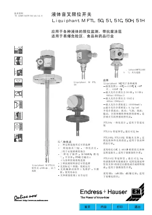
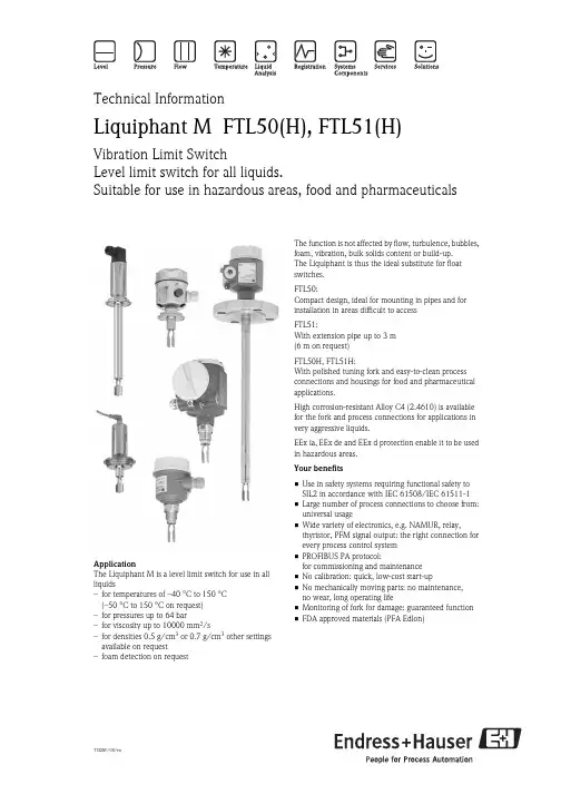
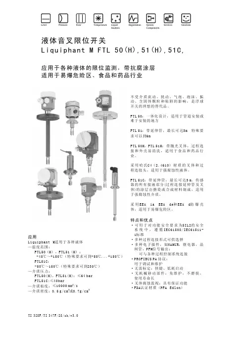
TI328F/00/enTechnical InformationLiquiphant M FTL50(H), FTL51(H)Vibration Limit SwitchLevel limit switch for all liquids.Suitable for use in hazardous areas, food and pharmaceuticalsApplicationThe Liquiphant M is a level limit switch for use in all liquids–for temperatures of –40 °C to 150 °C (–50 °C to 150 °C on request)–for pressures up to 64 bar–for viscosity up to 10000 mm 2/s–for densities 0.5 g/cm 3 or 0.7 g/cm 3 other settings available on request–foam detection on requestThe function is not affected by flow, turbulence, bubbles, foam, vibration, bulk solids content or build-up. The Liquiphant is thus the ideal substitute for float switches.FTL50:Compact design, ideal for mounting in pipes and for installation in areas difficult to access FTL51:With extension pipe up to 3 m (6 m on request)FTL50H, FTL51H:With polished tuning fork and easy-to-clean process connections and housings for food and pharmaceutical applications.High corrosion-resistant Alloy C4 (2.4610) is available for the fork and process connections for applications in very aggressive liquids.EEx ia, EEx de and EEx d protection enable it to be used in hazardous areas.Your benefits•Use in safety systems requiring functional safety to SIL2 in accordance with IEC 61508/IEC 61511-1•Large number of process connections to choose from: universal usage•Wide variety of electronics, e.g. NAMUR, relay,thyristor, PFM signal output: the right connection for every process control system •PROFIBUS PA protocol:for commissioning and maintenance •No calibration: quick, low-cost start-up•No mechanically moving parts: no maintenance, no wear, long operating life•Monitoring of fork for damage: guaranteed function •FDA approved materials (PFA Edlon)Liquiphant M FTL50(H), FTL51(H)2Endress+HauserTable of contentsApplication . . . . . . . . . . . . . . . . . . . . . . . . . . . . . . . . .4Level limit detection . . . . . . . . . . . . . . . . . . . . . . . . . . . . . . . . . . . 4Function and system design. . . . . . . . . . . . . . . . . . . . .4Measuring principle . . . . . . . . . . . . . . . . . . . . . . . . . . . . . . . . . . . 4Modularity . . . . . . . . . . . . . . . . . . . . . . . . . . . . . . . . . . . . . . . . . . 4Electronic versions for level limit switches . . . . . . . . . . . . . . . . . . 5Electronic versions for level sensor . . . . . . . . . . . . . . . . . . . . . . . . 5Galvanic isolation . . . . . . . . . . . . . . . . . . . . . . . . . . . . . . . . . . . . . 5Design . . . . . . . . . . . . . . . . . . . . . . . . . . . . . . . . . . . . . . . . . . . . . 5Input . . . . . . . . . . . . . . . . . . . . . . . . . . . . . . . . . . . . . .5Measured variable . . . . . . . . . . . . . . . . . . . . . . . . . . . . . . . . . . . . 5Measuring range (detection range) . . . . . . . . . . . . . . . . . . . . . . . . 5Product density . . . . . . . . . . . . . . . . . . . . . . . . . . . . . . . . . . . . . . 5Electronic insert AC, FEL51 . . . . . . . . . . . . . . . . . . . .6Electrical connection . . . . . . . . . . . . . . . . . . . . . . . . . . . . . . . . . . 6Output signal . . . . . . . . . . . . . . . . . . . . . . . . . . . . . . . . . . . . . . . . 6Signal on alarm . . . . . . . . . . . . . . . . . . . . . . . . . . . . . . . . . . . . . . 6Connectable load . . . . . . . . . . . . . . . . . . . . . . . . . . . . . . . . . . . . . 6Electronics AC, FEL51 in compact housing . . . . . . . . .7Electrical connection . . . . . . . . . . . . . . . . . . . . . . . . . . . . . . . . . . 7Output signal . . . . . . . . . . . . . . . . . . . . . . . . . . . . . . . . . . . . . . . . 7Signal on alarm . . . . . . . . . . . . . . . . . . . . . . . . . . . . . . . . . . . . . . 7Connectable load . . . . . . . . . . . . . . . . . . . . . . . . . . . . . . . . . . . . . 7Electronic insert DC PNP, FEL52. . . . . . . . . . . . . . . . .8Electrical connection . . . . . . . . . . . . . . . . . . . . . . . . . . . . . . . . . . 8Output signal . . . . . . . . . . . . . . . . . . . . . . . . . . . . . . . . . . . . . . . . 8Signal on alarm . . . . . . . . . . . . . . . . . . . . . . . . . . . . . . . . . . . . . . 8Connectable load . . . . . . . . . . . . . . . . . . . . . . . . . . . . . . . . . . . . . 8Power supply . . . . . . . . . . . . . . . . . . . . . . . . . . . . . . . . . . . . . . . . 8Electronics DC PNP, FEL52 in compact housing . . . . .9Electrical connection . . . . . . . . . . . . . . . . . . . . . . . . . . . . . . . . . . 9Output signal . . . . . . . . . . . . . . . . . . . . . . . . . . . . . . . . . . . . . . . 9Signal on alarm . . . . . . . . . . . . . . . . . . . . . . . . . . . . . . . . . . . . . 10Connectable load . . . . . . . . . . . . . . . . . . . . . . . . . . . . . . . . . . . . 10Power supply . . . . . . . . . . . . . . . . . . . . . . . . . . . . . . . . . . . . . . . 10Electronic insert AC/DC with relay output,FEL54 . . . . . . . . . . . . . . . . . . . . . . . . . . . . . . . . . . . .11Electrical connection . . . . . . . . . . . . . . . . . . . . . . . . . . . . . . . . . 11Output signal . . . . . . . . . . . . . . . . . . . . . . . . . . . . . . . . . . . . . . . 11Signal on alarm . . . . . . . . . . . . . . . . . . . . . . . . . . . . . . . . . . . . . 11Connectable load . . . . . . . . . . . . . . . . . . . . . . . . . . . . . . . . . . . . 11Power supply . . . . . . . . . . . . . . . . . . . . . . . . . . . . . . . . . . . . . . . 11Electronic insert 8/16 mA, FEL55. . . . . . . . . . . . . . .12Electrical connection . . . . . . . . . . . . . . . . . . . . . . . . . . . . . . . . . 12Output signal . . . . . . . . . . . . . . . . . . . . . . . . . . . . . . . . . . . . . . . 12Signal on alarm . . . . . . . . . . . . . . . . . . . . . . . . . . . . . . . . . . . . . 12Connectable load . . . . . . . . . . . . . . . . . . . . . . . . . . . . . . . . . . . . 12Electronic insert NAMUR L-H edge, FEL56. . . . . . . .13Electrical connection . . . . . . . . . . . . . . . . . . . . . . . . . . . . . . . . . 13Output signal . . . . . . . . . . . . . . . . . . . . . . . . . . . . . . . . . . . . . . . 13Signal on alarm . . . . . . . . . . . . . . . . . . . . . . . . . . . . . . . . . . . . . 13Connectable load . . . . . . . . . . . . . . . . . . . . . . . . . . . . . . . . . . . . 13Electronic insert NAMUR H-L edge, FEL58. . . . . . . .14Electrical connection . . . . . . . . . . . . . . . . . . . . . . . . . . . . . . . . . 14Output signal . . . . . . . . . . . . . . . . . . . . . . . . . . . . . . . . . . . . . . . 14Signal on alarm . . . . . . . . . . . . . . . . . . . . . . . . . . . . . . . . . . . . . 14Connectable load . . . . . . . . . . . . . . . . . . . . . . . . . . . . . . . . . . . . 14Electronics NAMUR H-L edge, FEL58in compact housing . . . . . . . . . . . . . . . . . . . . . . . . . .15Electrical connection . . . . . . . . . . . . . . . . . . . . . . . . . . . . . . . . . 15Output signal . . . . . . . . . . . . . . . . . . . . . . . . . . . . . . . . . . . . . . . 15Signal on alarm . . . . . . . . . . . . . . . . . . . . . . . . . . . . . . . . . . . . . 15Connectable load . . . . . . . . . . . . . . . . . . . . . . . . . . . . . . . . . . . . 15Electronic insert PFM, FEL57 . . . . . . . . . . . . . . . . . .16Electrical connection . . . . . . . . . . . . . . . . . . . . . . . . . . . . . . . . . 16Output signal . . . . . . . . . . . . . . . . . . . . . . . . . . . . . . . . . . . . . . . 17Signal on alarm . . . . . . . . . . . . . . . . . . . . . . . . . . . . . . . . . . . . . 17Connectable load . . . . . . . . . . . . . . . . . . . . . . . . . . . . . . . . . . . . 17Electronic insert PROFIBUS PA, FEL50A. . . . . . . . . .18Electrical connection . . . . . . . . . . . . . . . . . . . . . . . . . . . . . . . . . 18Output signal . . . . . . . . . . . . . . . . . . . . . . . . . . . . . . . . . . . . . . . 19Signal on alarm . . . . . . . . . . . . . . . . . . . . . . . . . . . . . . . . . . . . . 19Connection and function . . . . . . . . . . . . . . . . . . . . . .20Connecting cables . . . . . . . . . . . . . . . . . . . . . . . . . . . . . . . . . . . 20Fail-safe mode . . . . . . . . . . . . . . . . . . . . . . . . . . . . . . . . . . . . . . 20Switching time . . . . . . . . . . . . . . . . . . . . . . . . . . . . . . . . . . . . . . 20Switch-on behaviour . . . . . . . . . . . . . . . . . . . . . . . . . . . . . . . . . 20Performance characteristics. . . . . . . . . . . . . . . . . . . .20Reference operating conditions . . . . . . . . . . . . . . . . . . . . . . . . . . 20Maximum measured error . . . . . . . . . . . . . . . . . . . . . . . . . . . . . 20Repeatability . . . . . . . . . . . . . . . . . . . . . . . . . . . . . . . . . . . . . . . 20Hysteresis . . . . . . . . . . . . . . . . . . . . . . . . . . . . . . . . . . . . . . . . . 20Influence of medium temperature . . . . . . . . . . . . . . . . . . . . . . . 20Influence of product density . . . . . . . . . . . . . . . . . . . . . . . . . . . . 20Influence of medium pressure . . . . . . . . . . . . . . . . . . . . . . . . . . 20Operating conditions. . . . . . . . . . . . . . . . . . . . . . . . .21Installation. . . . . . . . . . . . . . . . . . . . . . . . . . . . . . . . .21Installation instructions . . . . . . . . . . . . . . . . . . . . . . . . . . . . . . . 21Examples of mounting . . . . . . . . . . . . . . . . . . . . . . . . . . . . . . . . 21Orientation . . . . . . . . . . . . . . . . . . . . . . . . . . . . . . . . . . . . . . . . 23Environment . . . . . . . . . . . . . . . . . . . . . . . . . . . . . . .23Ambient temperature range . . . . . . . . . . . . . . . . . . . . . . . . . . . . 23Ambient temperature limits . . . . . . . . . . . . . . . . . . . . . . . . . . . . 23Liquiphant M FTL50(H), FTL51(H) Storage temperature . . . . . . . . . . . . . . . . . . . . . . . . . . . . . . . . . . 24Climate class . . . . . . . . . . . . . . . . . . . . . . . . . . . . . . . . . . . . . . . 24Degree of protection . . . . . . . . . . . . . . . . . . . . . . . . . . . . . . . . . 24Vibration resistance . . . . . . . . . . . . . . . . . . . . . . . . . . . . . . . . . . 24Electromagnetic compatibility . . . . . . . . . . . . . . . . . . . . . . . . . . 24Medium conditions . . . . . . . . . . . . . . . . . . . . . . . . . . 24Medium temperature range . . . . . . . . . . . . . . . . . . . . . . . . . . . . 24Thermal shock . . . . . . . . . . . . . . . . . . . . . . . . . . . . . . . . . . . . . . 24Medium pressure pe . . . . . . . . . . . . . . . . . . . . . . . . . . . . . . . . . 24Test pressure . . . . . . . . . . . . . . . . . . . . . . . . . . . . . . . . . . . . . . . 24State of aggregation . . . . . . . . . . . . . . . . . . . . . . . . . . . . . . . . . . 24Density . . . . . . . . . . . . . . . . . . . . . . . . . . . . . . . . . . . . . . . . . . . 24Viscosity . . . . . . . . . . . . . . . . . . . . . . . . . . . . . . . . . . . . . . . . . . 24Solids content . . . . . . . . . . . . . . . . . . . . . . . . . . . . . . . . . . . . . . 24Mechanical construction . . . . . . . . . . . . . . . . . . . . . . 25Design . . . . . . . . . . . . . . . . . . . . . . . . . . . . . . . . . . . . . . . . . . . . 25Dimensions (in mm) . . . . . . . . . . . . . . . . . . . . . . . . . . . . . . . . . 26Weights . . . . . . . . . . . . . . . . . . . . . . . . . . . . . . . . . . . . . . . . . . . 30Material . . . . . . . . . . . . . . . . . . . . . . . . . . . . . . . . . . . . . . . . . . . 30Process connections . . . . . . . . . . . . . . . . . . . . . . . . . . . . . . . . . . 30Human interface . . . . . . . . . . . . . . . . . . . . . . . . . . . . 31Electronic inserts . . . . . . . . . . . . . . . . . . . . . . . . . . . . . . . . . . . . 31Compact housings . . . . . . . . . . . . . . . . . . . . . . . . . . . . . . . . . . . 32Operating concept . . . . . . . . . . . . . . . . . . . . . . . . . . . . . . . . . . . 34Certificates and approvals. . . . . . . . . . . . . . . . . . . . . 35General approvals . . . . . . . . . . . . . . . . . . . . . . . . . . . . . . . . . . . 35Other certificates . . . . . . . . . . . . . . . . . . . . . . . . . . . . . . . . . . . . 35Combination of housings and electronic inserts . . . . . . . . . . . . . 35Ordering information . . . . . . . . . . . . . . . . . . . . . . . . 37Product structure Liquiphant MFTL50. FTL51 . . . . . . . . . . . . . . . . . . . . . . . . . . . . . . . . . . . . . . 37Product structure Liquiphant MFTL50H, FTL51H . . . . . . . . . . . . . . . . . . . . . . . . . . . . . . . . . . . 41Accessories . . . . . . . . . . . . . . . . . . . . . . . . . . . . . . . . 44Welding boss G ¾ . . . . . . . . . . . . . . . . . . . . . . . . . . . . . . . . . . . 44Welding boss G 1 . . . . . . . . . . . . . . . . . . . . . . . . . . . . . . . . . . . . 44Welding boss G 1 . . . . . . . . . . . . . . . . . . . . . . . . . . . . . . . . . . . . 44Welding neck . . . . . . . . . . . . . . . . . . . . . . . . . . . . . . . . . . . . . . 44DRD welding flange . . . . . . . . . . . . . . . . . . . . . . . . . . . . . . . . . . 45Lap joint flange . . . . . . . . . . . . . . . . . . . . . . . . . . . . . . . . . . . . . 45Lap joint flanges . . . . . . . . . . . . . . . . . . . . . . . . . . . . . . . . . . . . . 45Sliding sleeves for unpressurised operation . . . . . . . . . . . . . . . . . 46High pressure sliding sleeves . . . . . . . . . . . . . . . . . . . . . . . . . . . 46Cover with sight glass . . . . . . . . . . . . . . . . . . . . . . . . . . . . . . . . 47Cover with sight glass . . . . . . . . . . . . . . . . . . . . . . . . . . . . . . . . 47Circular Connector . . . . . . . . . . . . . . . . . . . . . . . . . . . . . . . . . . 47Supplementary Documentation. . . . . . . . . . . . . . . . . 47KA . . . . . . . . . . . . . . . . . . . . . . . . . . . . . . . . . . . . . . . . . . . . . . 47BA . . . . . . . . . . . . . . . . . . . . . . . . . . . . . . . . . . . . . . . . . . . . . . . 48TI . . . . . . . . . . . . . . . . . . . . . . . . . . . . . . . . . . . . . . . . . . . . . . . 48SD . . . . . . . . . . . . . . . . . . . . . . . . . . . . . . . . . . . . . . . . . . . . . . . 48XA . . . . . . . . . . . . . . . . . . . . . . . . . . . . . . . . . . . . . . . . . . . . . . . 49SI . . . . . . . . . . . . . . . . . . . . . . . . . . . . . . . . . . . . . . . . . . . . . . . 493Endress+HauserLiquiphant M FTL50(H), FTL51(H)4Endress+HauserApplicationLevel limit detectionMaximum or minimum detection in tanks or pipes containing all kinds of liquids, including use in hazardous areas, food and pharmaceuticalsFunction and system designMeasuring principleThe sensor's fork vibrates at its intrinsic frequency.This frequency is reduced when covered with liquid. The change in frequency then activates a limit switch.ModularityLevel limit switchLiquiphant M FTL with electronic versions FEL51, FEL52, FEL54L00-FTL5xxxx-15-05-xx-xx-000Level sensorLiquiphant M FTL with electronic versions FEL55, FEL56, FEL57, FEL58for connecting to a separate switching unit or or an isolating amplifier FEL50Afor connecting to PROFIBUS PA segmentLiquiphant M FTL50(H), FTL51(H)Endress+Hauser 5Electronic versions for level limit switchesFEL51:Two-wire AC version;Switch the load directly into the power supply circuit via the thyristor.FEL52:Three-wire DC version;Switch the load via the transistor (PNP) and separate connection.FEL54:Universal current version with relay output;Switch the loads via 2 floating change-over contacts.Electronic versions for level sensor FEL55:For separate switching unit; signal transmission 16/8 mA along two-wire cabling.FEL56:For separate switching unit; signal transmission L-H edge 0.6…1.0 / 2.2…2.8 mA to EN 50227 (NAMUR) along two-wire cabling.FEL58:For separate switching unit; signal transmission H-L edge 2.2…3.5 / 0.6…1.0 mA to EN 50227 (NAMUR) along two-wire cabling.Checking of connecting cabling and other devices by pressing a key on the electronic insert.FEL57:For separate switching unit; PFM signal transmission;Current pulses superposed on the power supply along the two-wire cabling. Cyclical checking from the switching unit without changing levels.FEL50A:For connecting to PROFIBUS PA;Cyclic and acyclic data exchange acc. to PROFIBUS PA Profile 3.0 Discrete InputGalvanic isolationFEL51, FEL52, FEL50A:Between sensor and power supply FEL54:Between sensor and power supply and load FEL55, FEL56, FEL57, FEL58: See Switching unit connectedDesignFTL50: CompactFTL51:With extension pipeFTL50H:Compact, with polished tuning fork and hygienic process connections FTL51H:With extension pipe, polished tuning fork and hygienic process connectionsInputMeasured variable Level (limit value)Measuring range (detection range)FTL50:Depends on mounting point.FTL51:Depends on mounting point and the pipe extension. Standard 3000 mmm (up to 6000 mm on request)Product densityAdjustment on the electronic insert > 0.5 g/cm 3 or > 0.7 g/cm 3 (other on request)Liquiphant M FTL50(H), FTL51(H)6Endress+HauserElectronic insert AC, FEL51Electrical connectionTwo-wire AC connection Output signalSignal on alarm Output signal on power failure or in the event of damaged sensor: < 3.8 mAConnectable load•Permitted for relay with a holding power/rated power > 2.5 VA for 253 V (10 mA), min. 0.5 VA for 24 V (20 mA);•Relays with a lower holding power/rated power can be operated by means of an RC module connected in parallel (option).•Load switched directly into the power supply circuit via the thyristor.Transient (40 ms) max. 1.5 A, max. 375 VA at 253 V or max. 36 VA at 24 V (Not short-circuit proof);Continuous max. 89 VA at 253 V, max. 8.4 VA at 24 V;Voltage drop across FEL51 max. 12 V;Residual current with blocked thyristor max. 3.8 mA.Overvoltage protection FEL51: overvoltage category IIIAlways connect in series with a load!Check the following:•The residual current in blocked state (up to 3.8 mA)•that for low voltage–the voltage drop across the load is such that the minimum terminal voltage at the electronic insert (19 V) when blocked is not undershot.–the voltage drop across the electronics when switched through is observed (up to 12 V)•that a relay cannot de-energise with holding power below 3.8 mA.If this is the case, a resistor should be connected parallel to the relay.(RC module available on request).•When selecting the relay, pay attention to the holding power/rated power (See "Connectable load")IL< 3.8 mA xx-xx-000= load current(switched through)= residual current(blocked)= lit = unlitLiquiphant M FTL50(H), FTL51(H)Endress+Hauser 7Electronics AC, FEL51 in compact housingElectrical connectionTwo-wire AC connection Output signalSignal on alarm Output signal on power failure or in the event of damaged sensor: < 3.8 mAConnectable load•Permitted for relay with a holding power/rated power > 2.5 VA for 253 V (10 mA), min. 0.5 VA for 24 V (20 mA);•Relays with a lower holding power/rated power can be operated by means of an RC module connected in parallel (option).•Load switched directly into the power supply circuit via the thyristor.Transient (40 ms) max. 1.5 A, max. 375 VA at 253 V or max. 36 VA at 24 V (Short-circuit proof);Continuous max. 89 VA at 253 V, max. 8.4 VA at 24 V;Voltage drop across FEL51 max. 12 V;Residual current with blocked thyristor max. 3.8 mA.Overvoltage protection FEL51: overvoltage category IIIAlways connect in series with a load!Check the following:•The residual current in blocked state (up to 3.8 mA)•that for low voltage–the voltage drop across the load is such that the minimum terminal voltage at the electronic insert (19 V) when blocked is not undershot.–the voltage drop acrossthe electronics when switched through isobserved (up to 12 V).•That a relaycannot de-energise withholding power below 3.8 mA.If this is the case, a resistor should be connected parallel to the relay.(RC module available on request).IL< 3.8 mA xx-xx-000= load current(switched through)= residual current(blocked)= lit = unlitLiquiphant M FTL50(H), FTL51(H)8Endress+HauserElectronic insert DC PNP, FEL52Electrical connectionThree-wire DC connection Output signalSignal on alarm Output signal on power failure or in the event of damaged sensor: < 100 µA Connectable loadLoad switched via the transistor and separate PNP connection.Max. 55 V (pulsed overload and short-circuit protection);Continuous max. 350 mA;Max. 0.5 µF at 55 V, Max. 1.0 µF at 24 V;Residual voltage < 3 V (with transistor switched through);Residual current < 100 µA (with transistor blocked).Power supply10 V…55 V DCRipple max. 1.7 V, 0…400 Hz Current consumption max. 15 mA Power consumption max. 0.83 W Reverse polarity protectionOvervoltage protection FEL52: overvoltage category IIIPreferably used with programmable logic controllers (PLC).DI module as per EN 61131-2.Positive signal at switching output of the electronics (PNP);Output blocked on reaching limit.IL< 100 µA xx-xx-000= load current(switched through)= residual current(blocked)= lit = unlitLiquiphant M FTL50(H), FTL51(H)Endress+Hauser 9Electronics DC PNP, FEL52 in compact housingOutput signal With valve connector or cable tailIL< 100 µA xx-xx-000= load current(switched through)= residual current(blocked)= lit = unlitLiquiphant M FTL50(H), FTL51(H)10Endress+HauserWith M12x1 connector 52010285 (without LEDs)Signal on alarm Output signal on power failure or in the event of damaged sensor: < 100 µAConnectable loadLoad switched via the transistor and separate PNP connection.Max. 55 V (pulsed overload and short-circuit protection);Continuous max. 350 mA;Max. 0.5 µF at 55 V, max. 1.0 µF at 24 V;Residual voltage < 3 V (with transistor switched through);Residual current < 100 µA (with transistor blocked).Power supply10 V…55 V DCRipple max. 1.7 V, 0…400 Hz Current consumption max. 15 mA Power consumption max. 0.83 W Reverse polarity protectionOvervoltage protection FEL52: overvoltage category IIIxx-xx-002IL< 100 µA = load current(switched through)= residual current(blocked)xx-xx-000= lit = unlitElectronic insert AC/DC with relay output, FEL54Electrical connectionUniversal current connection with relay output Output signalSignal on alarm Output signal on power failure or in the event of damaged sensor: relay de-energisedConnectable loadLoads switched via 2 floating change-over contacts.I~ max. 6 A, U~ max. 253 V;P~ max.1500 VA, cos ϕ = 1, P~ max. 750 VA, cos ϕ > 0.7;I– max. 6 A to 30 V, I– max. 0.2 A to 125 V.When connecting a low-voltage circuit with double isolation according to IEC 1010 the following applies:total of voltages of relay output and power supply max. 300 V.Power supply19 V…253 V AC voltage, 50/60 Hz or DC voltage 19 V…55 V Power consumption max. 1.3 W Reverse polarity protectionOvervoltage protection FEL54: overvoltage category IIIPower supply:Please note the different voltage ranges for AC and DC.Output:When connecting an instrument with high inductance, provide a spark arrester to protect the relay contact.A fine-wire fuse (depending on the load connected) protects the relay contact on short-circuiting.Both relay contacts switch simultaneously.*When jumpered, the relay output works with NPN logic.L00-FTL5xxxx-07-05-xx-xx-001= relay energised = relay de-energised = lit = unlitElectronic insert 8/16 mA, FEL55Electrical connectionTwo-wire connection for separate switching unit Output signalSignal on alarm Output signal on power failure or in the event of damaged sensor: < 3.6 mA Connectable loadR = (U - 11 V) : 16.8 mAU = connection DC voltage 11 V…36 VOvervoltage protection FEL55: overvoltage category IIIFor connecting to programmable logic controllers (PLC).AI module 4-20 mA to EN 61131-2.Output signal jump from high to low current on limit.(H-L edge)~ 16 mA ~8 mA xx-xx-000= 16 mA ± 5 %= 8 mA ± 6 %= lit = unlitElectronic insert NAMUR L-H edge, FEL56Electrical connectionTwo-wire connection for separate switching unit Output signalSignal on alarm Output signal in the event of damaged sensor: > 2.2 mAConnectable loadSee Technical Data of isolating amplifier connected according to IEC 60947-5-6 (NAMUR)For connecting to isolating amplifiers acc. to NAMUR (IEC 60947-5-6),e.g. FXN421, FXN422, FTL325N, FTL375N or Commutec SIN100, SIN110 from Endress+Hauser.Output signal jump from low to high current on limit .(L-H edge)Connecting to multiplexer: Set clock time to min. 2 s.L00-FTL5xxxx-07-05-xx-xx-002= lit = flashes = unlitElectronic insert NAMUR H-L edge, FEL58Electrical connectionTwo-wire connection for separate switching unit Output signalSignal on alarm Output signal in the event of damaged sensor: < 1.0 mAConnectable loadSee Technical Data of isolating amplifier connected according to IEC 60947-5-6 (NAMUR). Connection also to isolating amplifiers which have special safety circuits (I > 3.0 mA).For connecting to isolating amplifiers acc. to NAMUR (IEC 60947-5-6), e.g. FXN421, FXN422, FTL325N, FTL375N or Commutec SIN100, SIN110 from Endress+Hauser.Output signal jump from high to low current on limit .(H-L edge)Additional function:Test key on the electronic insert.Pressing the key breaks the connection to the isolating amplifier.!Note!For Ex-d applications, the additional function can only be used if the housing is not exposed to an explosive atmosphere.Connecting to multiplexer:Set clock time to min. 2 s.L00-FTL5xxxx-07-05-xx-xx-002= lit = flashes = unlitElectronics NAMUR H-L edge, FEL58 in compact housingOutput signalSignal on alarm Output signal in the event of damaged sensor: < 1.0 mAConnectable loadSee Technical Data of isolating amplifier connected according to IEC 60947-5-6 (NAMUR). Connection also to isolating amplifiers which have special safety circuits (I > 3.0 mA).L00-FTL5xxxx-07-05-xx-xx-002= lit = flashes = unlitElectronic insert PFM, FEL57Electrical connectionTwo-wire connection for separate switching unit Switching behaviour of the connected device:Please note this switching response and function of the plant, especially when replacing a Liquiphant with an EL17Z or FEL37 electronic insert by a Liquiphant M with the FEL57 electronic insert.For connecting to switching units Nivotester FTL320, FTL325P, FTL370, FTL372, FTL375P (also with cyclical checking)Commutec SIF101, SIN111from Endress+Hauser.Output signal jump of PFM signal from high to low frequency when sensor is covered.Switching between minimum/maximum safety in the Nivotester.Additional function "cyclical checking":After interruption of the power supply,a test cycle is activated which checks the sensor and electronics without any change in level.Approved for overfill protection acc. to WHG, Germany.The following can be switched at the electronic insert:–Standard (STD):for low corrosive liquids; simulation approx. 8 stuning fork exposed – covered – exposed.–Extended (EXT):for highly corrosive liquids;simulation approx. 41 stuning fork exposed – covered – corroded – exposed.The check is activated and monitored at the switching unit.* De-energised on power supply failure。