A 12-GHz GaAs HBT VCO based on push-push output extraction from capacitive common-node
- 格式:pdf
- 大小:501.95 KB
- 文档页数:4

A Novel Model for Implementation of GammaRadiation Effects in GaAs HBTs Jincan Zhang,Yuming Zhang,Senior Member,IEEE,Hongliang Lu,Member,IEEE,Yimen Zhang,Senior Member,IEEE,and Min LiuAbstract—For predicting the effects of gamma radiation on gal-lium–arsenide(GaAs)heterojunction bipolar transistors(HBTs), a novel model is presented in this paper,considering the radiation effects.Based on the analysis of radiation-induced degradation in forward base current and cutoff frequency,three semiempirical models to describe the variation of three sensitive model parame-ters are used for simulating the radiation effects within the frame-work of a simplified vertical bipolar inter-company model.Its va-lidity was demonstrated by analysis of the experimental results of GaAs HBTs before and after gamma radiation.Index Terms—Cutoff frequency,forward base current,gamma radiation effects,heterojunction bipolar transistor(HBT),semi-conductor device modeling,vertical bipolar inter-company (VBIC).I.I NTRODUCTIONG ALLIUM–ARSENIDE(GaAs)heterojunction bipolartransistors(HBTs),due to their superior performance, are widely used in space radiation environments,and the recent boost of wireless and other high-end communications continue to draw more and more attention to its reliable long-term per-formance under radiation.Earlier studies on radiation effects on GaAs HBT have shown that GaAs HBTs are very attractive candidates for applications in space-based communication sys-tems[1],[2].In this case,many integrated circuits(ICs)have been designed with a GaAs HBT process[3]–[5].However, to improve the radiation hardness of HBT ICs,designers need electrical models taking account for the degradation induced by radiation.However,most of the radiation studies on GaAs HBTs re-ported thus far have mainly focused on the radiation induced changes from the experimental results with the measured elec-trical characteristics of the devices(e.g.,excess base current, cutoff frequency,etc.)[1],[2],[6],[7].To our knowledge,there is not much published information on modeling the electrical characteristics of HBTs subjected to high-energy radiations[8]. The work of modeling the effects of gamma radiation on the dc characteristics of GaAs HBTs has been studied in our pre-vious work[9].However,the complexity of the radiation-in-Manuscript received May03,2012;revised September16,2012;accepted September20,2012.This work was supported by the National Basic Research Program of China under Grant2010CB327505,the Advance Research Project of China under Grant51308030306,and the Advance Research Foundation of China under Grant9140A08030511DZ111.The authors are with the Microelectronics Institute,Xidian University,Xi’an, Shaanxi710071,China(e-mail:zjc850126@).Digital Object Identifier10.1109/TMTT.2012.2221137duced degradation processes makes it difficult to develop a de-tailed physical model of the device after radiation.An alter-native semiempirical approach is to develop an improved ver-tical bipolar inter-company(VBIC)model to describe electrical characteristics of the device before and after irradiation.One can use the extracted model parameters to describe the degra-dation of sensitive model parameters as a function of radiation dose,and then assemble the device model.We believe that such an approach is very useful to predict the degradation effects of devices.There were reports for simulating radiation-induced degradation of dc characteristics in bipolar transistors of silicon based on the semiempirical approach[10],[11].However,very little progress has been made in modeling the degradation of ac characteristics as a function of radiation dose in bipolar transis-tors based on the semiempirical approach,which is now studied in this work.In this paper,a novel model for implementation of gamma ra-diation effects in GaAs HBTs is developed.This paper is orga-nized as follows.The novel model based on a simplified VBIC model is presented in Section II.To validate the validity of the model,the experimental results of GaAs HBTs under gamma radiation are shown in Section III.The modeled results are com-pared with the measured results in Section IV and conclusions are presented in Section V.II.M ODELThe VBIC model was defined by a group of representa-tives from IC and computer-aided design(CAD)industries to overcome the shortcomings of the Spice Gummel Poon(SGP) model.The equivalent network of VBIC is given in[12].There are several improvements comparing with the SGP model, such as temperature-dependence modeling,quasi-saturation modeling,and decoupling of base and collector currents. However,special characteristics of HBTs make it possible to consider a simplified VBIC model,as shown in Fig.1.In this simplified VBIC model,the following assumptions are consid-ered.1)There is no parasitic pnp transistor in npn HBTs[13];there-fore,the parameters to describe the parasitic transistor can be eliminated.2)The extrinsic base–emitter current and chargecan be neglected compared to the intrinsic base–emitter current and charge,respectively.3)Since de-embedding the parasitic parameters has beendone,base–collector small-signal capacitance and base–emitter small-signal capacitance can be ig-nored.0018-9480/$31.00©2012IEEEFig.1.Simplified VBIC model.4)In HBTs,both early voltages and knee currents for the for-ward and reverse operations can be considered to be infi-nite[14],therefore the normalized base charge tends to be1.The validity of the model to describe HBTs characteristics has been verified in our earlier work[15].Unfortunately,the simplified VBIC model also has not taken account of the par-ticular effects of radiation on the electrical behavior of devices. However,HBTs are significantly degraded when exposed to ra-diation.Forward base current and cutoff frequency are mainly affected.A.Forward Base CurrentIn the measurement of forward-mode Gummel plot,the base current is measured when isfixed at zero while the base–emitter junction is in forward bias.The presence of the relatively large valence band discontinuity at the base–emitter heterointerface leads to effective suppression of the hole current injected from the base region into the emitter.Thus,the base current is mostly determined by the recombination of:1)in the bulk and along the periphery of the base–emitter space-charge region(BE-SCR)and2)in the bulk and at the surface of the neutral base region(NBR).In the simplified VBIC model,the total forward base current for low-level injection where voltage drop across parasitic re-sistances can be neglected is followed by(1) where is the thermal voltage.As can be seen from (1),the base current includes a component,formed by the NBR recombination modeled with saturation current and ideality factor,and a component,caused by the BE-SCR recombination modeled with saturation currentand ideality factor.Radiation-induced degradation in the forward base current of HBTs is attributed to excess carrier recombination including ra-diation-induced traps in the BE-SCR[9],whereas excess base current defined as the difference between the post-radi-ation and pre-radiation base current can be experimentally ex-tracted by the variations of and with radiation dose. In this case,(1)will be improved as(2),in which radiation-in-duced excess saturation current and excess ideal factor are included.(2)B.Cutoff FrequencyPhysically,can be expressed as(3)(4)(5) where is the base–emitter junction capacitor charge time,is the base–collector junction capacitor charge time,is the base transit time,and is the base–collector space-charge region delay time.It has been shown that capacitance and resistance are slightly or even not degraded under radiation for HBTs in our previous works[16],Therefore,the degradation of is mainly caused by the increase of the transit time,which is just the sum of the variations of and in the compact model[17].In the simplified VBIC model,the transit time is modeled as(6) where is the forward transit time,is the variation of with basewidth modulation,is the coefficient of bias dependence,is the coefficient of dependence on, is the coefficient of dependence on,and is the forward collector current.Inserting a parameter related to the variation of due to radiation effect,the equation of the transit time can be im-proved as(7) where radiation-induced excess forward transit time is used to predict the increase of,in turn to describe the degra-dation of.III.E XPERIMENTSIn order to determine the regulations of,,and with radiation dose,and verify the validity of the presented model,the following radiation experiment has been performed.ZHANG et al.:NOVEL MODEL FOR IMPLEMENTATION OF GAMMA RADIATION EFFECTS IN GaAs HBTs3Fig.2.Radiation-induced degradation of base current for different total dose levels.The devices applied in the experiment are GaAs HBTs with a single fabrication batch from the WIN Semiconductors Corpo-ration,Tao Yuan Shien,Taiwan(type Q1H201B1).The width and length of each emitter mesa for Q1H201B1are1and20 m,respectively.Radiation of devices,without bias,was im-plemented in a“Gamma-Cell”with a Co source providing a dose rate of about50rd(Si)/s rd Si rd GaAs, and radiation time of5.5,16.5,38.5,and55h,equivalent to a gamma total dose of1,3,7,and10Mrd(Si),respectively.In order to get enough accurate test data,there were four test sam-ples under every radiation total dose mentioned above.Before the experiment,the samples were carefully selected to ensure the differences of performances among the16tested HBTs to be less than3%and the spread of the measured data for the four devices at each radiation to be within0.1%.All of samples were measured at room temperature K before and after radiation.On-chip forward dc Gummel characteristic measure-ments were made with an HP4142Semiconductor Analyzer. Scattering parameters(-parameters)were measured using an HP8510C vector network analyzer from100MHz to40GHz, and in a wide bias current range based on circuit applications.A.Forward Base CurrentFig.2shows the plot of measured versus with the base–collector junction shorted for different total dose radiation, while the collector current remains approximately unchanged. As can be seen from thisfigure,at low current levels,the curve shows significant change after radiation.In the high current regime,almost has no change.The increase rate of base current,defined as the ratio of excess base current to pre-radiation base current,is plotted with incremental dose values,as shown in Fig.3.The increase rate increases with the total dose,and reaches620%at V after a gamma total dose of10Mrd(Si).However,as can be seen from Fig.3,the increase rate of base current versus decreases.In the regime of V,the increase rate becomes close to0.Fig.4shows the effect of the total dose on the excess base current for different total dose levels.The results presented are limited in the low injection current region where the excess base current remains significant compared with thevalue of the total base current.The excess basecurrent is approximately linear throughout the biasrange with a slope of the idea factor Fig.3.Increase rate of forward base current.Fig.4.Radiation-induced excess base current.Fig.5.versus collector current for different total dose levels..These results indicate that radiation-induced recombi-nation mechanism in the BE-SCR is more dominant in the ex-cess base current.Thus,it is reasonable that only the and parameters associated with the BE-SCR are improved in the novel model,as shown in(2).There are two possible recombination mechanisms in the BE-SCR to be consistent with the measured base current ide-ality factor[18].One is trap-assisted tunneling due to gamma radiation induced traps.The second possible mecha-nism is the recombination from a nonuniform distribution of Shockley–Read–Hall centers within the BE-SCR.B.Cutoff FrequencyThe cutoff frequency was extracted using-parameters measurements in the common-emitter configuration by extrap-olating.Fig.5shows measured versus collector current for different total dose levels.In general,relatively obvious degradation is observed for the GaAs HBT after10-Mrd(Si)ra-diation.4IEEE TRANSACTIONS ON MICROWA VE THEORY ANDTECHNIQUESing fly-backing fly-back measurement.The emitter series resistance was measured with the fly-back technique in which the emitter is grounded and current is forced into the base.The open circuit collector voltage was measured.The emitter resistance is taken as the slope of the linear segment of the curve.Fig.6shows the comparison of from fly-back measurement curves before and after 10-Mrd(Si)radiation.As can be seen from this figure,there is almost no change in .In the simpli fied VBIC model,includes the extrinsic col-lector resistance and intrinsic collector resistance .Fig.7shows from fly-back measurement curves to be similar to measurement.The value of is equal to the slope of the linear segment of the curve,and has no change after radiation.can be determined by optimizing the fitting to quasi-saturation region data of common-emitter char-acteristics.It can then be obtained that there is almost no change in .The possible reason for almost unchanged and after radiation is that the doped concentration in HBT devices is high,which makes radiation induced a little reduction of carrier con-centration causing no obvious increment in and .Fig.8shows the comparison of the capacitances for the GaAs HBT.The curves nearly coincide,suggesting that even after 10-Mrd(Si)total dose gamma radiation,the capacitances almost do not change.According to the measured results,it can be concluded that the degradation of is only due to the change of ,which validates the correctness of the discussion in Section II-B.IV .A NALYSIS AND D ISCUSSIONTo predict the electrical behavior of ICs for a given radiation total dose,designers usually need an ef ficient evaluation oftheFig.8.Capacitances (and )for GaAs HBT.TABLE I V ALUES OF,,,AND P ARAMETERS FOR P RE -R ADIATIONAND P OST -R ADIATION OF D IFFERENT R ADIATION L EVELSradiation parameters embedded in sensitive device model pa-rameters to determine the degradation of these parameters with dose.Such an approach permits an easy implementation for ra-diation-induced degradation in the electrical simulator,such as the Advanced Design System (ADS),by means of symbolically de fined device (SDD),which is an equation-based module to en-able designer to quickly and easily de fine custom and nonlinear components.Furthermore,this approach,which allows reason-able computation time,is generally preferred for the applica-tions of complex physics with large numbers of parameters.A.Forward Base CurrentTo extract the forward Gummel base current parameters,theand parameters can be determined from the inter-cept and the slope of the plot in the region of low .The values of and are then easily obtained by fitting the curve in the high injection region.The obtained ,,,and parameter values are listed in Table I for pre-radiation and post-radiation of different radiation levels.The extracted curves for and versus total dose are plotted in Fig.9(a)and (b),respectively.A saturation effect is exhibited for high total doses.The objective functions for fitting and are shown in (8)and (9),respec-tively,where Dose represents the gamma radiation total dose [in Mrd(Si)]and ,,,,,and are fitting parametersDose (8)Dose(9)As can be seen from Fig.9(a)and (b),the fitting curves of the first four dose levels (first four modeled)nearly coincide with that of all the five dose levels (modeled).The values of and at Dose Mrd(Si)obtained from the first four modeled,modeled,and measured are shown in Table II.ThereZHANG et al.:NOVEL MODEL FOR IMPLEMENTATION OF GAMMA RADIATION EFFECTS IN GaAs HBTs5(a)(b)Fig.9.(a)Comparison of the measured and modeled.(b)Comparisonof the measured and modeled.TABLE IIVALUES OFANDP ARAMETERS AT DoseMrd(Si)parison of the measured and first four modeled excess base cur-rent for 10-Mrd(Si)gamma radiation.are little deviations between the measured values and the firstfour modeled values.The error between the measured excess base current and the excess base current based on first four modeled is less than 5%for the fifth total dose 10Mrd(Si),as depicted in Fig.10.Thus,it can be concluded that the novel model should be able to pre-dict accurately the radiation-induced degradation in excess base current even after more than 10-Mrd(Si)gammaradiation.The measured and modeled forward base current for dif-ferent total doses is drawn in Fig.11.The modeled results parison of the measured and modeled forward base current for different total dose levels.TABLE IIIV ALUES OF,,,,AND P ARAMETER FOR P RE -R ADIATION AND P OST -R ADIATION OF D IFFERENT R ADIATION L EVELSmatch the measured data reasonably well (the error within 2%)up to V.The difference between the measured and modeled increases up to 3%for the high injection current region because our model does not account for the degradation of the NBR.However,this mismatch is still not bad.B.Cutoff FrequencyIn order to extract the transit time parameters,the forward transit time is obtained from the intercept of against the curve.The ,,,and param-eters of the transit time are further estimated by optimization.Table III presents the extracted ,,,,and parameter values for pre-radiation and post-radiation of dif-ferent radiation levels.It seems that parameters do not change much between pre-radiation and post-radiation.Since the most susceptible transistor materials to be sensitive to the total dose effect are insulators,the SiN insulator instead of oxides in the GaAs HBTs does not show serious degradation to the total dose effect.To describe the decrease of ,the following objective func-tion is used to describe excess forward transit time :Dose(10)where ,,and are fitting parameters.The measured and modeled versus total dose is pre-sented in Fig.12.The fitting curve based on the first four dose levels almost entirely coincides with that based on all five dose levels,suggesting that the novel model should be able to predict the degradation of cutoff frequency under more than 10-Mrd(Si)gamma radiation.The cutoff frequency versus is illustrated in Fig.13for different total dose levels with a maximum error less than 1%in the all-bias range.6IEEE TRANSACTIONS ON MICROWA VE THEORY ANDTECHNIQUESparison of the measured and modeled.parison of the measured and modeled cutoff frequency for dif-ferent total dose levels.V .C ONCLUSIONA novel model to include total dose effects for HBTs has been presented in this paper.To predict the behavior of ICs in space-like environments,semiempirical models for radiation parameters as a function of radiation total dose have been pro-posed.By incorporating the radiation parameters into sensitive model parameters,a novel model based on a simpli fied VBIC model has been implemented to simulate accurately the radia-tion-induced degradation in forward base current and cutoff fre-quency at least 10-Mrd(Si)gamma total dose.Our analysis also shows that the model can possibly predict the electrical charac-teristics of HBTs even more than 10-Mrd(Si)gamma radiation;however,further experimental study is required to prove the de-duction.R EFERENCES[1]S.M.Zhang,G.F.Niu,J.D.Cressler,S.J.Mathew,U.Gogineni,S.D.Clark,P.Zampardi,and R.L.Pierson,“A comparison of the effects of gamma radiation on SiGe HBT and GaAs HBT technologies,”IEEE Trans.Nucl.Sci.,vol.47,no.6,pp.2521–2527,Dec.2000.[2]S.Vuppala,C.S.Li,P.Zwicknagl,and S.Subramanian,“Neutron,proton and electron radiation effects in InGaP/GaAs single hetero-junc-tion bipolar transistors,”IEEE Trans.Nucl.Sci.,vol.50,no.6,pp.1846–1851,Dec.2003.[3]U.Karthaus,D.Sukumaran,S.Tontisirin,S.Ahles,A.Elmaghraby,L.Schmidt,and H.Wagner,“Fully integrated 39dBm,3-stage doherty PA MMIC in a low-voltage GaAs HBT technology,”IEEE Microw.Wireless Compon.Lett.,vol.22,no.2,pp.94–96,Feb.2012.[4]N.G.Constantin,P.J.Zampardi,and M.N.El-Gamal,“Automatichardware recon figuration for current reduction at low power in RFIC PAs,”IEEE Trans.Microw.Theory Techn.,vol.59,no.6,pp.1560–1570,Jun.2011.[5]K.Yamamoto,H.Kurusu,S.Suzuki,and M.Miyashita,“High-direc-tivity enhancement with passive and active bypass circuit techniques for GaAs MMIC microstrip directional couplers,”IEEE Trans.Mi-crow.Theory Techn.,vol.59,no.12,pp.3095–3107,Dec.2011.[6]E.P.Wilcox,S.D.Phillips,P.Cheng,T.Thrivikraman,A.Madan,J.D.Cressler,G.Vizkelethy,P.W.Marshall,C.Marshall,J.A.Babcock,K.Kruckmeyer,R.Eddy,G.Cestra,and B.Y.Zhang,“Single event transient hardness of a new complementary npn pnp SiGe HBT technology on thick-film SOI,”IEEE Trans.Sci.,57,no.6,pp.3293–3297,Dec.2010.[7]S.Díez,M.Lozano,G.Pellegrini,F.Campabadal,I.Mandic,D.Knoll,B.Heinemann,and M.Ullán,“Proton radiation damage on SiGe:C HBTs and additivity of ionization and displacement effects,”IEEE Trans.Nucl.Sci.,vol.56,no.4,pp.1931–1936,Aug.2009.[8]M.V.Uffelen,S.Geboers,P.Leroux,and F.Berghmans,“Spice mod-elling of a discrete COTS SiGe HBT for digital applications up to MGy dose levels,”IEEE Trans.Nucl.Sci.,vol.53,no.4,pp.1945–1949,Aug.2006.[9]J.C.Zhang,Y.M.Zhang,H.L.Lu,Y.M.Zhang,and S.Yang,“Themodel parameter extraction and simulation for the effects of gamma ir-radiation on the DC characteristics of InGaP/GaAs single heterojunc-tion bipolar transistors,”Microelectron.Reliab.,Art.ID MR-D-11-00657,to be published.[10]X.Montagner,R.Briand,P.Fouillat,R.D.Schrimpf,A.Touboul,K.F.Galloway,M.C.Calvet,and P.Calve1,“Dose-rate and irradiation temperature dependence of BJT spice model rad-parameters,”IEEE Trans.Nucl.Sci.,vol.45,no.3,pp.1431–1437,Jun.1998.[11]X.Montagner,P.Fouillat,R.Briand,R.D.Schrimpf,A.Touboul,K.F.Galloway,M.C.Calvet,and P.Calvel,“Implementation of total dose effects in the bipolar junction transistor Gummel–Poon model,”IEEE Trans.Nucl.Sci.,vol.44,no.6,pp.1922–1929,Dec.1997.[12]C.C.McAndrew,J.A.Seitchik,D.F.Bowers,M.Dunn,M.Foisy,I.Getreu,M.McSwain,S.Moinian,J.Parker,D.J.Rouston,M.Schroter,P.van Wijnen,and L.F.Wagner,“VBIC95:The vertical bipolarinter-company model,”IEEE J.Solid-State Circuits ,vol.31,no.10,pp.1476–1483,Oct.1996.[13]S.V.Cherepko and J.C.M.Hwang,“VBIC model applicability andextraction procedure for InGaP/GaAs HBT,”in –Paci fic Mi-crow.Conf.,2001,pp.716–721.[14]W.Liu,“Switching characteristics and spice models,”in Handbook ofIII–V Heterojunction Bipolar Transistors .New York:Wiley,1998,pp.1088–1090.[15]J.C.Zhang,Y.M.Zhang,H.L.Lu,Y.M.Zhang,S.Yang,and P.Yuan,“A simpli fied VBIC model and SDD implementation for InP DHBT,”in IEEE Int.Electron Devices and Solid-State Circuits Conf.,Tianjin,China,2011,pp.1–2.[16]S.Yang,H.L.Lu,Y.M.Zhang,Y.M.Zhang,J.C.Zhang,and H.P.Zhang,“The effects of gamma irradiation on GaAs HBT,”in IEEE Int.Electron Devices and Solid-State Circuits Conf.,Tianjin,China,2011,pp.1–2.[17]J.Ge,Z.Jin,Y.B.Su,W.Cheng,X.T.Wang,G.P.Chen,and X.Y.Liu,“A physics-based charge-control model for InP DHBT including current-blocking effect,”Chinese Phys.Lett.,vol.26,no.7,pp.1–4,2009.[18]G.A.Schrantz et al.,“Neutron radiation effects on AlGaAs/GaAs het-erojunction bipolar transistors,”IEEE Trans.Nucl.Sci.,vol.35,no.6,pp.1657–1661,Dec.1988.Jincan Zhang,photograph and biography not available at time of publication.Yuming Zhang (M’01–SM’05),photograph and biography not available at time of publication.Hongliang Lu (M’07),photograph and biography not available at time of pub-lication.Yimen Zhang (SM’91),photograph and biography not available at time of pub-lication.Min Liu,photograph and biography not available at time of publication.。

低噪声C波段MMIC VCO
江兴
【期刊名称】《半导体信息》
【年(卷),期】2004(000)005
【摘要】<正> Hittite Microwave公司新近开发出一对GaAs/InGaP HBT MMIC压控振荡器(VCO),VCO与电阻、负阻器件、变容二极管及缓冲放大器集成,其工作频率为5.0~6.1GHz。
这两种型号为HMC430LP4和HMC431LP4的VCO适用于C波段无线局域网、甚小孔径终端、点到点无线电设备等。
上述两种型号的VCO无需外部元件,使用+3V单电源,耗电27mA。
其封装为塑料表面安装封装。
HMC430LP4在5.0~5.5GHz、100KHz相噪偏移下的缓冲输出功率为+2dBm,相噪仅—103dBc/Hz;HMC431LP4在5.5~6.1GHz、100KHz相噪偏移下的缓冲输出功率
【总页数】2页(P35-36)
【作者】江兴
【作者单位】
【正文语种】中文
【中图分类】TN752
【相关文献】
1.低噪声C波段MMIC VCO [J],
2.Hittite Microwave宽带MMIC VCO [J],
3.Ku波段源极调谐HFET MMIC VCO [J], 王绍东;高学邦;吴洪江;吴阿惠
4.基于准MMIC技术的12~18GHz宽带VCO(英文) [J], 王绍东;高学邦;吴洪江;王向玮;默立冬
5.S波段低相位噪声HBT MMIC VCO [J], 陈新宇;林金庭;陈效建
因版权原因,仅展示原文概要,查看原文内容请购买。

设计应用技术Telecom Power Technology相位噪声/(d B c /H z )1-160-150-140-130-120-110-100-190-80-70-6010100频率偏移/kHz1 00010 000相位噪声/(d B c /H z )1-160-150-140-130-120-110-100-190-80-70-6010100频率偏移/kHz1 00010 000 2023年10月25日第40卷第20期25号混频后,通过低通滤波器滤除高频分量,再取其差频作为主环鉴相器的射频信号;综合相位噪声、频率切换时间等指标,采用4级有源环,并选取合适的环路带宽,降低鉴相泄露;对各器件供电电源进行充分的隔离滤波,防止电源串扰。
1.2.2 空间串扰产生的杂散优化设计混频环内部同时存在主环信号、副环信号、中频信号,需要对不同的信号进行隔离处理,防止不同信号空间串扰。
该产品结构通过压框将主环信号、副环信号、中频信号进行分腔,并且每个隔腔进行单独封盖处理,减小不同信号空间串扰。
1-160-150-140-130-120-110相位噪声/(d B c /H z )-100-90-80-706010100k 频率偏移/kHz1 00010 000 (a )相位噪声 (b )杂散图4 混频环测试结果2 测试结果混频环的测试结果如图4所示。
由测试结果可知,该混频环的输出频率为16~20 GHz ,步进频率为100 MHz ,相位噪声为-111 dBc/Hz@1 kHz ,杂散为-60 dBc 。
其中,混频环-111 dBc/Hz@1 kHz 的相位噪声实测值较图3中主环-112 dBc/Hz@1 kHz 的相位噪声仿真值恶化1 dB ,这是由于图2中副环 -114 dBc/Hz@1 kHz 的相位噪声未优于图3中主环-112 dBc/Hz@1 kHz 的相位噪声6 dB 以上,混频过程相位噪声恶化导致的,后续可根据测试结果优化副环相位噪声。

华中科技大学硕士学位论文LTCC手机前端模块DCS/PCS频段设计姓名:***申请学位级别:硕士专业:微电子学与固体电子学指导教师:***20070601摘要随着全球移到通信进入3G时代,手机成为日常生活中的必需品。
人们对手机的性能、尺寸和价格提出了更高要求。
LTCC技术凭借其立体布线优势、优异的微波/射频性能和与半导体IC工艺的良好兼容性而成为无源集成的一项关键技术。
由于手机射频前端部分含有大量无源元件,FEM成为利用LTCC的典型器件。
然而,国内在LTCC 技术方面至少落后发达国家五年,目前国内手机中使用的FEM几乎全部依赖进口,研究设计LTCC产品具有重要意义。
本文完成了一款GSM制式双频段手机前端模块和一款三频段手机前端模块的设计(其中双频段已流片生产),所设计的FEM结构新颖、体积小巧、性能优良。
材料、工艺和设计是LTCC技术的三大关键因素。
本文重点放在设计方面,从GSM 手机前端模块的电路结构设计到在LTCC介质基板中的三维结构实现,对整个设计流程做了较为全面的分析。
在电路结构设计部分,主要讨论了采用集总参数传输零点滤波器实现天线双工器和采用PIN管实现天线开关的设计方法。
在三维结构实现部分,本文从基本的电感电容等无源元件的三维建模、各部分电路在LTCC介质基板内部的布局到整个模块的仿真优化都做了详细的分析和讨论。
最后将我们设计的一款FEM样品的测试结果与市场上同类型的商用产品进行了分析比较,结果表明我们设计的FEM 样品各项参数指标达到商用要求,有的指标优于商用产品。
关键词:手机前端模块滤波器 LTCC 电磁耦合多层结构AbstractAs global mobile communications get into the third-generation, handsets become necessary in daily life. People make higher demand on the size, performance and cost of the handsets. Low temperature co-fired ceramic(LTCC) technology,which has excellent electrical performance at RF and microwave frequencies, compatibility with semiconductor IC technics , with its main advantage of there-dimensional(3-D) design, has became an important technology of passive integration. The RF part of mobile phone has a lot of passive devices, so FEM becomes of a typical LTCC device. In china, however, LTCC technology trailed the developed countries by at least 5 years, most of the LTCC products are imports. This paper Designed a 2-band and a 3-band FEM using LTCC technology. The FEM designed by us has small size, novel structure, and good performance.Material, manufacture and design are key elements of LTCC technology. This paper focuses on the design,and researches on LTCC front-end module(FEM). It introduces the circuit design and the 3-D structure realization in detail. The circuit design part mainly introduces the duplexer design with lumped apices filter, and the antenna switch design with PIN diode. The 3-D structure realization part introduces the modeling of passive devices and the EM simulation of the whole structure of the module. At the last, it compares a 2-band FEM sample, which is designed by us, with a commercial product of the same type, the measured results of the sample are almost the same as the commercial product, and some parameters of the sample are better than the commercial product .Keywords:front-end module filter LTCC EM coupled multilayer structure独创性声明本人声明所呈交的学位论文是我个人在导师的指导下进行的研究工作及取得的研究成果。

传统来说,一部可支持打电话、发短信、网络服务、APP应用的手机,一般包含五个部分部分:射频部分、基带部分、电源管理、外设、软件。
射频部分:一般是信息发送和接收的部分;基带部分:一般是信息处理的部分;电源管理:一般是节电的部分,由于手机是能源有限的设备,所以电源管理十分重要;外设:一般包括LCD,键盘,机壳等;软件:一般包括系统、驱动、中间件、应用。
在手机终端中,最重要的核心就是射频芯片和基带芯片。
射频芯片负责射频收发、频率合成、功率放大;基带芯片负责信号处理和协议处理。
那么射频芯片和基带芯片是什么关系?射频芯片和基带芯片的关系先讲一下历史,射频(Radio Frenquency)和基带(Base Band)皆来自英文直译。
其中射频最早的应用就是Radio——无线广播(FM/AM),迄今为止这仍是射频技术乃至无线电领域最经典的应用。
基带则是band中心点在0Hz的信号,所以基带就是最基础的信号。
有人也把基带叫做“未调制信号”,曾经这个概念是对的。
例如AM为调制信号,无需调制,接收后即可通过发声元器件读取内容。
但对于现代通信领域而言,基带信号通常都是指经过数字调制的,频谱中心点在0Hz的信号。
而且没有明确的概念表明基带必须是模拟或者数字的,这完全看具体的实现机制。
射频电路方框图接收电路的结构和工作原理接收时,天线把基站发送来电磁波转为微弱交流电流信号经滤波,高频放大后,送入中频内进行解调,得到接收基带信息(RXI-P、RXI-N、RXQ-P、RXQ-N);送到逻辑音频电路进一步处理。
该电路掌握重点:接收电路结构;各元件的功能与作用;接收信号流程。
电路结构接收电路由天线、天线开关、滤波器、高放管(低噪声放大器)、中频集成块(接收解调器)等电路组成。
早期手机有一级、二级混频电路,其目的把接收频率降低后再解调(如下图)。
接收电路方框图各元件的功能与作用1)、手机天线:结构如下图,由手机天线分外置和内置天线两种;由天线座、螺线管、塑料封套组成。
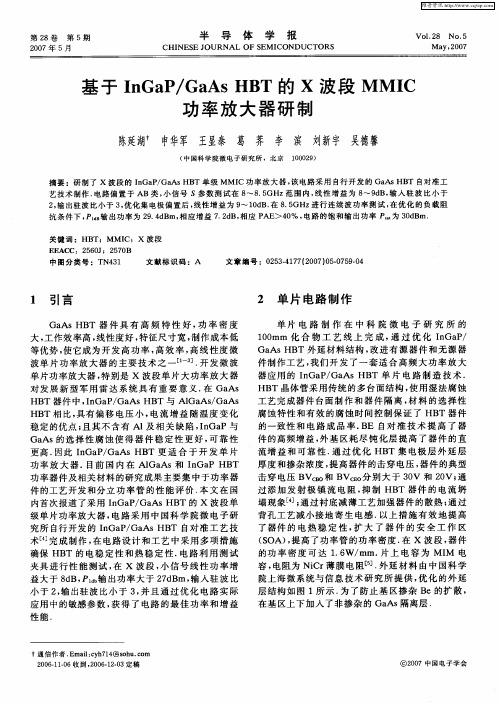
Units GHz GHz dBm dBm dBc/Hz dBc/Hz dBc dBc dBcMHz/VoltVDC VDC mAMin.14.7 1.84---------+1.0-Typ.--+5.0+2.0-88.0-113.0-35.0-45.0-42.040.0+4.0-110Max.15.71.96---------+6.013014.7-15.7 GHz GaAs MMIC Voltage Controlled OscillatorFeaturesOn-Chip Prescaler+5.0 dBm Output Power-35 dBc Harmonic Suppression -88 dBc/Hz @ 100KHz Phase Noise 110mA @ 4.0V Bias Supply100% On-Wafer, DC and Output Power Testing 100% Visual Inspection to MIL-STD-883Method 2010General DescriptionParameterSupply Voltage (Vcc1,2,3)Supply Voltage (Vtune)Supply Current (Icc1,2,3)Supply Current (Itune)Storage Temperature (Tstg)Operating Temperature (Ta)Junction Temperature (Tjn)+5.0 VDC +7.0 VDC 150 mA 1 mA -65 to +165 O C -55 to MTTF Table MTTF Table Chip Device Layout(1) Junction temperature affects a device's MTTF. It is recommended to keep channel temperature as low as possible for maximum life.11Mimix Broadband's 14.7-15.7 GHz GaAs HBT VCO is a fully integrated oscillator MMIC with on-chip frequency doubler and divide-by-8 prescaler (w.r.t RFout). This design is based on a cross coupled differential pair with on-chip tuning diode and resonator. The use of a high-Q resonator structure and integrated varactor diodes results in optimum phase-noise performance, whilst the integration of frequency doubler and prescaler reduce application complexity and time-to-market. This MMIC uses Mimix Broadband's 2 um GaAs HBT device model technology to ensure low flicker (1/f) noise and high reliability. The chip has surface passivation to protect and provide a rugged part with backside via holes and gold metallization to allow either a conductive epoxy or eutectic solder die attach process. This device is well suited forMillimeter-wave Point-to-Point Radio, LMDS, SATCOM and VSAT applications.Electrical Characteristics (Ambient T emperature T = 25 o C)Absolute Maximum RatingsFrequency Range (f)Prescaler Frequency Range (f)Fundamental Output Power (Pout)Prescaler Output Power (Pout)SSB Phase Noise @ 100 kHz Offset SSB Phase Noise @ 1 MHz Offset Subharmonic Suppression 2nd Harmonic Suppression 3rd Harmonic Suppression Frequency Pushing (Vcc)Supply Voltage (Vcc)Frequency Tuning Voltage (Vtune)Supply Current (Icc) (Vcc=4.0V Typical)April 2007 - Rev 17-Apr-07X Q 1006-B DOscillator Measurements14.7-15.7 GHz GaAs MMIC Voltage Controlled OscillatorXQ1006-BD Output Frequency vs. Tuning VoltageF o u t (GH z )April 2007 - Rev 17-Apr-07XQ1006-BD Kvco vs. Tuning VoltageP o u t (d B m )1324567X Q 1006-B D2.000(0.079)0.732Mechanical Drawing14.7-15.7 GHz GaAs MMIC Voltage Controlled OscillatorApril 2007 - Rev 17-Apr-07App Note [1] Biasing - As shown in the bonding diagram, this device is operated by separately biasing Vcc (1,2,3) and Vtune with Vcc(1,2,3)= +4.0 V and Vtune = +1.0 to +6.0 V, Icc1=30mA, Icc2=10mA, Icc3=70mA.App Note [2] Bias Arrangement - Each DC pad (Vcc1, 2, 3 and Vtune) needs to have DC bypass capacitance. (~100 - 200 pF, 100pF max on Vtune) as close to the device as possible. Prescaler output (RF Div1, RF Div2) can be used differential or single-end as required.T14.7-15.7 GHz GaAs MMIC Voltage Controlled OscillatorApril 2007 - Rev 17-Apr-07Handling and Assembly InformationCAUTION! - Mimix Broadband MMIC Products contain gallium arsenide (GaAs) which can be hazardous to the human body and the environment. For safety, observe the following procedures:Do not ingest.Do not alter the form of this product into a gas, powder, or liquid through burning, crushing, or chemical processing as these by-products are dangerous to the human body if inhaled, ingested, or swallowed.Observe government laws and company regulations when discarding this product. This product must bediscarded in accordance with methods specified by applicable hazardous waste procedures.14.7-15.7 GHz GaAs MMIC Voltage Controlled OscillatorLife Support Policy - Mimix Broadband's products are not authorized for use as critical components in life support devices or systems without the express written approval of the President and General Counsel of MimixBroadband. As used herein: (1) Life support devices or systems are devices or systems which, (a) are intended for surgical implant into the body, or (b) support or sustain life, and whose failure to perform when properly used in accordance with instructions for use provided in the labeling, can be reasonably expected to result in asignificant injury to the user. (2) A critical component is any component of a life support device or system whose failure to perform can be reasonably expected to cause the failure of the life support device or system, or to affect its safety or effectiveness.ESD - Gallium Arsenide (GaAs) devices are susceptible to electrostatic and mechanical damage. Die are supplied in antistatic containers, which should be opened in cleanroom conditions at an appropriately grounded anti-static workstation. Devices need careful handling using correctly designed collets, vacuum pickups or, with care,sharp tweezers.Die Attachment - GaAs Products from Mimix Broadband are 0.100 mm (0.004") thick and have vias through to the backside to enable grounding to the circuit. Microstrip substrates should be brought as close to the die aspossible. The mounting surface should be clean and flat. If using conductive epoxy, recommended epoxies are Tanaka TS3332LD, Die Mat DM6030HK or DM6030HK-Pt cured in a nitrogen atmosphere per manufacturer's cure schedule.Apply epoxy sparingly to avoid getting any on to the top surface of the die. An epoxy fillet should be visible around the total die periphery. For additional information please see the Mimix "Epoxy Specifications for Bare Die" application note.If eutectic mounting is preferred, then a fluxless gold-tin (AuSn) preform, approximately 0.0012 thick, placed between the die and the attachment surface should be used. A die bonder that utilizes a heated collet and provides scrubbing action to ensure total wetting to prevent void formation in a nitrogen atmosphere is recommended. The gold-tineutectic (80% Au 20% Sn) has a melting point of approximately 280 ºC (Note: Gold Germanium should be avoided). The work station temperature should be 310 ºC +/- 10 ºC. Exposure to these extreme temperatures should be kept to minimum. The collet should be heated, and the die pre-heated to avoid excessive thermal shock. Avoidance of air bridges and force impact are critical during placement.Wire Bonding - Windows in the surface passivation above the bond pads are provided to allow wire bonding to the die's gold bond pads. The recommended wire bonding procedure uses 0.076 mm x 0.013 mm (0.003" x0.0005") 99.99% pure gold ribbon with 0.5-2% elongation to minimize RF port bond inductance. Gold 0.025 mm (0.001") diameter wedge or ball bonds are acceptable for DC Bias connections. Aluminum wire should beavoided. Thermo-compression bonding is recommended though thermosonic bonding may be used providing the ultrasonic content of the bond is minimized. Bond force, time and ultrasonics are all critical parameters.Bonds should be made from the bond pads on the die to the package or substrate. All bonds should be as short as possible.April 2007 - Rev 17-Apr-07Part Number for Ordering DescriptionXQ1006-BD-000V Where “V” is RoHS compliant die packed in vacuum release gel paksXQ1006-BD-EV1XQ1006 die evaluation module。
MMIC是单片微波集成电路的缩写,是在半绝缘半导体衬底上用一系列的半导体工艺方法制造出无源和有源元器件,并连接起来构成应用于微波(甚至毫米波)频段的功能电路。
单片微波集成电路,即MMIC是Monolithic Microwave Integrated Circuit 的缩写,它包括多种功能电路,如低噪声放大器(LNA)、功率放大器、混频器、上变频器、检波器、调制器、压控振荡器(VCO)、移相器、开关、MMIC收发前端,甚至整个发射/接收(T/R)组件(收发系统)。
由于MMIC 的衬底材料(如GaAs、InP)的电子迁移率较高、禁带宽度宽、工作温度范围大、微波传输性能好,所以MMIC具有电路损耗小、噪声低、频带宽、动态范围大、功率大、附加效率高、抗电磁辐射能力强等特点。
国外概况自1974年,美国的Plessey公司用GaAs FET作为有源器件,GaAs半绝缘衬底作为载体,研制成功世界上第一块MMIC放大器以来,在军事应用(包括智能武器、雷达、通信和电子战等方面)的推动下,MMIC的发展十分迅速。
80年代,随着分子束外延、金属有机物化学汽相淀积技术(MOCVD)和深亚微米加工技术的发展和进步,MMIC发展迅速。
1980年由Thomson-CSF和Fujitsu两公司实验室研制出高电子迁移率晶体管(HEMT),在材料结构上得到了不断的突破和创新。
1985年Maselink用性能更好的InGaAs沟道制成的赝配HEMT(PHEMT),使HEMT向更调频率更低噪声方向发展。
继HEMT之后,1984年用GaAlAs/GaAs异质结取代硅双极晶体管中的P-N结,研制成功了频率特性和速度特性更优异的异质结双极晶体管(HBT)和HBT MMIC。
由于InP材料具有高饱和电子迁移率、高击穿电场、良好的热导率、InP基的晶格匹配HEMT,其性能比GaAs基更为优越,近年来随着InP单晶的制备取得进展,InP基的HEMT、PHEMT、MMIC性能也得到很大的提高。