EP3000 iverter SPEC
- 格式:pdf
- 大小:719.18 KB
- 文档页数:1

3000W PowerVerter RV Inverter/Charger with Hardwire Input/OutputMODEL NUMBER: RV3012OEM Highlights12V DC or 120V AC input; 120V AC output (hardwired)3000 watts continuous, 4500FeaturesRV3012OEM serves as an automotive or stationary DC-to-AC inverter with automatic line-to-battery transfer and integrated battery chargerSupports 120V AC output from a 120V AC line power source or 12V DC battery source16.6 millisecond automatic transfer between line and battery power supports UPS protection during blackouts and voltage fluctuations for equipmentcompatible with a one cycle transfer time3000 watts continuous AC output in inverter mode, 4800 watts continuous via dual circuit AC output in AC modeDouble Boost inverter output supports momentary startup loads up to 200% of the continuous rating for up to 10 secondsOverPower inverter output supports longer duration overloads to 150% for 1-60 minutes under ideal battery and temperature conditions.(For best results, utilize OverPower usage for as short of a duration as possible, ensure battery bank and cabling is able to provide full nominal DC voltage under load and allow inverter/charger to fully cool before and after OverPower usage.)3 stage, selectable 35/140 amp battery charger with adjustable settings for wet/gel battery types offers fast, reliable battery rechargingProtected hardwire bolt-down input lugs safely accept heavy gauge input wiring from attached battery bankProtected hardwire output passes 120V line power or inverter output through to connected equipment. Includes optional dual-circuit hardwire AC input to enable full charger output from the first 120V 20A circuit and full AC pass-through from the second 120V 20A input feedReliability enhanced large-transformer design tested to UL(USA) and CSA(Canada) standardsMoisture-resistant construction enables vehicular or marine operation in high humidity environments3 position operating mode switch supports "AUTO" mode to enable automatic transfer between DC and AC modes, CHARGE-ONLY to maintain a fullbattery charge when AC is present without auto transfer and SYSTEM OFF settingsSet of six front panel LEDs display AC/DC operational modes, overload status, DC voltage level, shutdown status and system fault statusSet of 4 configuration dipswitches support wet/gel battery charging profiles, adjustable 135/145V high voltage auto transfer during overvoltages and selectable 75/85/95/105V AC low voltage auto transfer during brownoutsSet of 4 additional configuration dipswitches support 4 levels of charger limiting relative to output load size, a battery equalization program and battery charger low/high settingsResettable 30A charger AC input breaker and resettable dual 20A branch-rated AC output breakers and automatic 2 speed cooling fan protect the inverter from load and temperature related failuresGrounding lug properly connects the inverter/charger system to earth ground or vehicle grounding systemAutomatic overload and thermal shutoff safely turns off inverter as excessive loads or overheating conditions developFront panel remote control connector enables remote off/on switching(requires APSRM4 switch accessory). Optional APSRM4 accessory also includes user configurable jacks to support inverter shutoff or startup as a vehicle ignition is engagedLoad sensing control dial enables adjustable load threshold required to automatically turn the inverter on and off in DC mode as load conditions change Includes battery temperature sensor with 20 foot cable to prolong battery life by adjusting the charge level based on battery temperatureAutomatic Generator Starter jack enables user configuration of automatic generator startup as inverter batteries drop to 11.5VDC and generator shutoff as inverter batteries are recharged to 14.1VDCSpecificationsOUTPUTFrequency Compatibility60 HzOutput Receptacles HardwireOutput (Watts)3000Continuous Output Capacity (Watts)3000Peak Output Capacity (Watts)6000Output Nominal Voltage120VOutput Voltage Regulation LINE POWER (AC): Maintains 120V nominal sine wave output from line power source. INVERTER POWER (AC):Maintains PWM sine wave output voltage of 120 VAC (+/-5%).Output Frequency Regulation60 Hz (+/- 0.3 Hz)Overload Protection Includes 30A input breaker dedicated to the charging system and 2 branch rated 20A output load breakersPure Sine Wave Output NoINPUTNominal Input Voltage(s) Supported120V ACRecommended Electrical Service DC INPUT: Requires 12VDC input source capable of delivering 290A for the required duration (when used at fullcontinuous capacity - DC requirements increase during Over-Power and Double-Boost operation).Maximum Input Amps / Watts DC INPUT: Full continuous load - 282A at 12VDC. AC INPUT: 40 amps total (20A line 1 / 20A line 2) at 120VAC with full inverter and charger load (25A max charger-only from line 1 / combined input load to support charger and AC output is automatically controlledInput Connection Type DC INPUT: Set of 4 DC bolt-down terminals (2 red / 2 black). AC INPUT: hardwire (2 input circuits - see manual) Input Cord Length Details DC INPUT: User supplies cabling. 0 gauge or larger (see manual). AC INPUT: hardwireVoltage Compatibility (VAC)120Voltage Compatibility (VDC)12BATTERYExpandable Battery Runtime Runtime is expandable with any number of user supplied wet or gel type batteriesDC System Voltage (VDC)12Battery Pack Accessory (Optional)98-121 sealed lead acid battery(optional)Battery Charge35A / 140A (selectable)LVC (Low Voltage Cut-Off)10V DC +/-3%Expandable Runtime YesUSER INTERFACE, ALERTS & CONTROLSFront Panel LEDs Set of 6 LEDs offer continuous status information on load percentage (6 levels reported) and battery charge level (7levels reported). See manual for sequences.Switches 3-position on/off/remote switch enables simple on/off power control plus auto/remote setting that enables distant on/off control of the inverter system when used in conjunction with APSRM4 accessory(sold separately) in inverter mode. In AC uninterruptiblSURGE / NOISE SUPPRESSIONAC Suppression Joule Rating450PHYSICALShipping Dimensions (hwd / in.)15.25 x 16 x 24Shipping Dimensions (hwd / cm)38.74 x 40.64 x 60.96Shipping Weight (lbs.)67.7Shipping Weight (kg)30.7Unit Dimensions (hwd / in.)9.75 x 11.5 x 16.75Unit Dimensions (hwd / cm)24.77 x 29.21 x 42.55Unit Weight (lbs.)62.6Unit Weight (kg)28.4Cooling Method Multi-speed fanMaterial of Construction SteelForm Factors Supported Mounting slots enable permanent placement of inverter on any horizontal surface (see manual for additionalmounting information)ENVIRONMENTALRelative Humidity0-95% non-condensingLINE / BATTERY TRANSFERTransfer Time (Line Power to Battery Mode)16.6 milliseconds (typical - compatible with many computers - verify transfer time compatibility of loads for UPS applications)Low Voltage Transfer to Battery Power In AC "auto" mode, inverter/charger switches to battery mode as line voltage drops to 75V (user adjustable to 85, 95, 105V - see manual)High Voltage Transfer to Battery Power In AC "auto" mode, inverter/charger switches to battery mode as line voltage increases to 135V (user adjustable to 145 - see manual)SPECIAL FEATURESLoad Sensing Optional load sense function enables automatic inverter shutoff and startup as connected equipment is powered off and on. Front panel load sense potentiometer can be set to shutoff or turn on inverter power in response to loads of any level, up to 150 watts.Remote Control Capability YesCERTIFICATIONSCertifications Tested to UL458 (USA) and CSA (Canada)WARRANTYProduct Warranty Period (U.S. &Canada)30-month limited warrantyProduct Warranty Period(International)1-year limited warrantyProduct Warranty Period (Mexico)30-month limited warrantyProduct Warranty Period (Puerto30-month limited warrantyRico)© 2015 Tripp Lite. All rights reserved. All product and company names are trademarks or registered trademarks of their respective holders. Use of them does not imply any affiliation with or endorsement by them. Tripp Lite has a policy of continuous improvement. Specifications are subject to change without notice. Tripp Lite uses primary and third-party agencies to test its products for compliance with standards. See a list of Tripp Lite's testing agencies:/products/product-certification-agencies。

危险在通电的状态下, 因内部存在高电压,所以控制柜门打开之前, 先把主电源切断。
不然的话, 因高压触电, 会有致人身伤亡的危险。
警告如不遵守本说明书上要求的操作方法的话, 会引起产品故障或使用者受伤。
1.电源投入之前, 确认3相主电源R、S、T的电压和连接状态。
2.按照说明书上要求的屏蔽处理及起动程序,机房上的运行操作稳定、安全之前,千万不要在较厢里或较顶上进行工作。
电气冲击本表是表示不遵守说明书上要求的程序的场合会发生电击危险的部分。
SICON-3000CCi 编码器连接 (5)1章. SICON-3000CCi 使用说明书 (6)1. 产品概况 (6)1-1. 安装前的注意事项 (6)1-2. 特征 (7)2. 开箱检查注意事项 (8)3. 形式及规格 (9)3-1. 控制器的构成 (9)3-2. 控制器的形式符号及规格 (11)4. 功能说明 (12)4-1. 端子信号说明 (12)5. 安装 (13)5-1. 安装时的注意 (13)5-2. 接线时候注意事项 (13)5-3. 限位开关和平层感应板 ( 60m /min 的时候) (14)5-4. 井道安装 (15)5-5. 楼层显示板安装 (15)5-6. 门机驱动装置设置 (16)6. 起动说明书 (17)6-1. 运行之前 (17)6-1-1. 基本设置 (17)6-2. 变频器自学习以及手动运行 (18)6-2-1 变频器自学习以及手动运行(使用异步电机时) (18)6-2-2 变频器自学习以及手动运行(使用同步电机时) (21)6-3. 楼层高度测定(Calibration) (24)6-3-1. 进行楼高度测定之前 (24)6-3-2. 实施楼层高度测定 (25)6-3-3. 楼层测定完毕后(OPP 设定) (25)6-4. 自动运行 (25)2 章. OPP-2000 (调试器) (26)1. OPP-2000 产品概况 (26)1-1. 产品概况 (26)1-2. OPP-2000的外形图 (26)2. OPP-2000 Menu (27)2-1. Main Menu (27)2-2. Category Menu (27)3. OPP-2000 Menu 说明 (28)3-1. Main Menu (28)3-1-1. 可变 Menu窗 (30)3-2. Category Menu (36)3-2-1. Mode Menu (36)3-2-2. View Menu (38)3-2-3. Setup Menu (41)3-2-4. OPT menu (51)3-2-5. PROG menu (55)3-2-6. DISP menu (57)3-2-7. VER menu (58)3-2-8. PWORD menu (58)4. Error Code (60)4-1. Error Code 形式 (60)4-2. Error Code 表 1 (60)4-3. Error Code 表 2 (67)3 章. MCB-3000CCi (主控板) (69)1. MCB-3000CCi Board 构成图 (69)2. Connector 说明 (70)3. Jumper Pin 说明 (76)4. DIP 开关说明 (76)5. LED 说明 (77)6. Test Pin 说明 (77)4 章. OPB-101 Board (轿顶通讯板) (78)1. OPB-101 Board 构成图 (78)2. Connector 说明 (79)3. DIP 开关说明 (83)4. LED 说明 (83)5. FUSE 说明 (83)6. Load Sensor(称重装置) 输入说明 (84)6-1. Analog Load Sensor 安装 (84)6-2. Analog Load Sensor(0%,100%) 输入数值设定 (85)6-3. Analog Load Sensor的 CH0和 CH1 输入不正常时候 (85)1章. SICON-3000CCi 使用说明书1. 产品概况本文件是有关SAMIL ELTEC公司 SICON-3000CCi 控制柜的使用说明书。

EMC TESTS, SEMINARS, HARD AND SOFTWARETechnical SpecificationNo. ESD3000.docrevised: 23.06.20061 Tester Type ESD3000-SystemThe ESD3000 is the newly designed hand held ESD discharge tester from EMC Partner. The ESD3000 simulates different discharges such as contact and air discharges in accordance with IEC 61000-4-2 and several other standards. When discharge modules or relay module with discharge networks are added the ESD3000 can be expanded to comply with test standards up to 30 kV.1 Tester Type ESD3000-System 12 General ESD3000 System of EMC-PARTNER 22.1 Overview on ESD3000 system 22.1.1 ESD3000 Contact Discharge (CD) up to max. 10kV with Discharge Module (DM ) 22.1.2 ESD3000 Contact Discharge (CD) up to 30 kV) with Relay Module (RM), DischargeNetwork (DN) 22.2 ESD3000 with Discharge Modules (DM). Voltages: Contact Discharge (CD) up to 10 kVand Air Discharge (AD) up to 30 kV 32.2.1 Accessories Discharge Modules (DM) 32.2.2 Overview Discharge Module (DM) - Standards - C, R, Voltage ranges 32.2.3 Customised Discharge Modules DM - C, R, Voltage ranges 32.3 ESD3000 with Relay Module (RM), Contact Discharge (CD) up to 30 kV and Air Discharge(AD) up to 30 kV 42.3.1 Accessories Discharge Networks DN 42.3.2 RM32 - DN - Standards - C, R, Voltage ranges 42.3.3 Modules for Special Applications 53 Generator, Technical Data 53.1 Mechanical dimensions, climatic conditions 53.2 Technical data 63.2.1 ESD high voltage circuit - Example ESD3000DM1 63.2.2 ESD control circuit 64 ESD3000 Accessories 74.1.1 ESD3000 Remote control Software 9 IntroductionThe ESD3000 can be operated as stand alone or together with the TRA2000 from EMCP. The TEMA software to the ESD3000 is the most sophisticated software for Transient Immunity tests.The ESD3000 generator is compact and has an excellent value for money.•All relevant parameters in one display•Easy parameter changes during operation•Voltage generation up to 30 kV positive and negative•Commercially available standard rechargeable or non-rechargeable batteries can be used•Low weight only 870 grams•Ergonomic form of the ESD3000•The additional module can be easily interchanged2 General ESD3000 System of EMC-PARTNER2.1 Overview on ESD3000 systemDischarge Module (DM)ESD3000Sharp Tip forcontact discharge (CD)Rounded Tip for air discharge (AD) 30 mm Tip Electrode for (AD) V > 16 kVBatteries standard VM size 32.1.1 ESD3000 Contact Discharge (CD) up to max. 10kV with Discharge Module (DM )Relay Module (RM)Discharge Network (DN)ESD3000Sharp Tip forcontact discharge (CD) Rounded Tip for air discharge (AD) 30 mm Tip Electrode for (AD) V > 16 kVBatteries standard VM size 32.1.2 ESD3000 Contact Discharge (CD) up to 30 kV) with Relay Module (RM), Discharge Network (DN)2.2 ESD3000 with Discharge Modules (DM). Voltages: Contact Discharge (CD)up to 10 kV and Air Discharge (AD) up to 30 kV• The equipment ESD3000 include a rechargeable battery pack and a charger. The battery capacity is designed to operate at highest level and 1 Hz repetition one full work day (8 hours).• For long term ESD evaluation the ESD3000 can be set on top of a support (standard M5 thread). • The discharge modules must be selected from the list below. For contact discharge a sharp tip and for air discharge a rounded tip is included.2.2.1 Accessories Discharge Modules (DM)The modules contain the high voltage source and the impulse network, therefore the discharge modules are in an optimum way designed to specified voltage range and impulse shaping network of standards. The modules can be easily interchanged. Discharge Module (DM) include waveform calibration according the listed standard. All DM will be shipped with calibration report. At any time DM’s can be ordered after the first delivery with a calibration report.2.2.2 Overview Discharge Module (DM) - Standards - C, R, Voltage ranges DM-Modules Standards Cap /Res. Voltage range (CD)Contact Discharge Voltage range (AD)Air Discharge DM1 IEC 61000-4-2 150 pF / 330 Ohm +/- 0.2 up to 10 kV +/- 0.2 up to 16 kV DM2 ISO TR10605 330 pF / 2000 Ohm +/- 0.2 up to 10 kV+/- 0.2 up to 16 kV DM3ISO TR10605150 pF / 2000 Ohmno CD + and -1 up to 30 kV DM4 MIL-STD-464 MIL-STD-883 GR78-CORE 100 pF / 1500 Ohm+/- 0.2 up to 10 kV+/- 0.2 up to 16 kVDM5RTCA/DO-160150 pF / 330 Ohmno CD + and -1 up to 30 kVDM6 IEC 61340-3-1 JEDEC 22-A114 MIL-STD-750D 100 pF / 1500 Ohm+/- 0.2 up to 8 kVno ADDM7 IEC 61340-3-2 JEDEC 22-A115 200 pF / 0 Ohm+/- 0.08 up to 2.5 kV no AD DM8 IEC 60571 EN50155 rise time < 0.05usduration 0.1us +/- 0.2 up to 10 kV+/- 0.2 up to 16 kV2.2.3 Discharge Modules DM – for spezial applications DM-Modules Standards Cap / Res. Voltage range CD Voltage range AD DM16-CAR3ISO TR 10605 330pF / 330 Ohm +/- 0.2 up to 10 kV +/- 0.2 up to 16 kV DM16-CAR4 ISO TR 10605 150pF / 2000 Ohm +/- 0.2 up to 10 kV+/- 0.2 up to 16 kV DM16-C63-HAND ANSI C63.16 330pF / 150 Ohm no CD +/- 0.2 up to 16 kVDM16-C63-HAND ANSI C63.16330pF / 150 Ohm+/- 0.2 up to 8 kVNo AD2.3 ESD3000 with Relay Module (RM), Contact Discharge (CD) up to 30 kV andAir Discharge (AD) up to 30 kV•For the 30 kV contact application the discharge module are divided into two part the relay module and the discharge networks. The relay module include the discharge and the polarity switch. The relay module generates the first current peak. The discharge networks generate the second part of the wave mainly determined by the C and R value and the charging voltage.•The discharge network includes the impulse capacitor, the discharge resistor and the high voltage generation.•The discharge networks must be selected from the list below.•The relay module includes a sharp tip for contact discharge and a rounded tip for air discharge.2.3.1 Accessories Discharge Networks DNThe Discharge Network contain the high voltage source and the impulse network, therefore the discharge modules are designed specifically to requirements of voltage range and impulse shaping network of applicable standards. The networks are easily interchanged. RM and DN networks include waveform calibrations according to the listed standard. All RM plus DN will be shipped with calibration report. At any time Discharge Networks (DN) can be ordered after the first delivery with a calibration report.2.3.2 RM32 - DN - Standards - C, R, Voltage rangesRM-Module Rise time firstcurrent peakCap /Res. Voltage range CD Voltage range ADRM32 0.7 up to 1 ns no specificcomponents+/- 1 up to 30 kV +/- 1 up to 30 kVAvailable networks that can be used together with the RM32 relay module are listed below. When the rise time 0.7 to 1 ns differs in a standard or an additional safety switch is required (e.g. explosive system testing) a filter network FN must be added. Customised FN on demand.DN-Module Standard Cap /Res. Voltage range CD Voltage range AD DN1 IEC61000-4-2RTCA/DO-160GMW 3100150pF / 330 Ohm +/- 1 up to 30 kV +/- 1 up to 30 kV DN2 ISOTR10605SAEJSSI-ISFORD AB/ACGMW3100330pF / 2000 Ohm +/- 1 up to 30 kV +/- 1 up to 30 kV DN3 ISOTR10605SAEJSSI-ISFORD AB/AC150pF / 2000 Ohm +/- 1 up to 30 kV +/- 1 up to 30 kVDN4 MIL-STD-331BSTANAG 4239ISO14304500pF / 5000 Ohm +/- 1 up to 30 kV +/- 1 up to 30 kVDN5 MIL-STD-331MIL-DTL-23659DSTANAG 4239500pF / 500 Ohm +/- 2 up to 30 kV +/- 2 up to 30 kV DN6 ISO TR10605 330pF / 330 Ohm +/- 2 up to 30 kV +/- 2 up to 30 kV2.3.3 Discharge Network DN - for Special Applications DN-Module Standards Cap / Res. Range Voltage range CD Voltage range AD CAR1JASO D 001-94150pF / 500 Ohm +/- 2 up to 30 kV +/- 2 up to 30 kV CAR5 Renault 32-10-001/D 330pF / 0 Ohm +/- 2 up to 30 kV +/- 2 up to 30 kV IND1 IEC801-2 150pF / 150 Ohm +/- 2 up to 30 kV +/- 2 up to 30 kV MIL2 ?400pF / 150 Ohm +/- 2 up to 30 kV +/- 2 up to 30 kV MIL3MIL-STD-1576500pF / 0 Ohm+/- 2 up to 30 kV+/- 2 up to 30 kV3 Generator, Technical Data3.1 Mechanical dimensions, climatic conditionsThe Tester ESD3000 is a hand held equipment TypeDimension L x D x H [ mm ]Weight [ g ]RemarksESD3000 with DM 340 x 70 x 190 mm 870 with batteries 1050 gDM alone 340 x 70 x 190 mm 355 RM alone 138 x diameter 68 350DN alone 131 x diameter 57 mm 270 Case450 x 350 x 120 mm3000Power adapter95 up to 250 V ( 50 /60 Hz )Power consumptionoperation mode< 20 VA Standby < 0 VAEnvironment conditionsTemperature range °C 0 to 40 °C Humidity rh % 30 to 60% Pressure kPa86 to 106Accessories included with ESD3000:• Power adapter with Lemo plug (type 1s 7 4 pin FFP.1s.304.CLAC47)• Earth connection cable (length 2 m) • One set of rechargeable batteries (NIMH)• User manual (1 pce)• EMCP E3Loader software • Verification Report3.2 Technical data3.2.1 ESD high voltage circuit - Example ESD3000DM1Energy storage capacitance 150 pF ± 10% Discharge resistance 330 Ω ± 10% Charging resistance > 50 M Ω holding time (drop to 95%) better than 5 sCurrent rise time, 2 Ω load 0,7 to 1 nsDefinition of current waveform: Current amplitude at 30 ns 2 A / kV ± 30% Current amplitude at 60 ns 1 A / kV ± 30% Voltage range …air discharge“ 0.5 to 16 kV ± 10% Voltage range …contact discharge“ 0.5 to 10 kV ± 10% First current amplitude into 2 Ω …contact discharge“ 3.75 A / kV± 10%ESD3000 with DMESD3000 with RM+DN3.2.2 ESD control circuit Polaritypositive / negative; automatic switchover Number of discharges Detection of the number of discharges-preselectable 1 up to 30000 -count every pulse or countdischarge only. Only the impulses whereas the voltage of thedischarge capacitor dropes lower then 10% of the charging voltage are counted.Rampsvoltage amplitude or polarity change after a predefined number of dischargesReportingtest sequence with the number of discharges -Voltage amplitude -PolarityDischarge modes:-Air discharge (AD) -Contact discharge (CD)Repetition of the discharges 0.055 up to 99 s or single discharge Note: The repetition rates are applicable to IEC61000-4-2 only. For all other modules or applications consult the relevant DM(Discharge Module) or DN (Discharge Network) specific Instruction sheets.4 ESD3000 AccessoriesESD-STAND3:Height adjustable from 0.4 mup to 1.75 mApplication:long term tests in contact andair discharge modeESD-VERI-V: 20 G divider for high voltagemeasurement on theESD3000 up to 25 kV.Ratio is determined by 1 MOhm input of theoscilloscope.Ration approximate 20’000ESD-TARGET1: 2 Ohm target with N connectorand N-BNC adapter, upperlimit approximately 2 GHzVCP05: Vertical coupling plate.Mechanical dimension: 0.5 x0.5 mApplication indirect ESDdischarge with contact tip.ESD3000DM-EXT Testing of EUTs that couldspontaneously explode orrapidly change state, such asairbags or munitions fusesCNH12Accessory to ESD3000 with RM32 and DN1 to simulate rapidly changing H-field as generated at real ESD discharge.TC-MIG24EDTest cabinet to protect operators when testingexplosive devices such as air bag initiators or fuses.Safety SwitchAccessory to ESD3000 with RM32 to make sure thegeenrator is discharged fully before conencting explosive devices.ESD-OPTOLINKAccessory to ESD3000 with RM32 and DN1 to simulate rapidly changing H-field as generated at real ESD discharge.4.1.1 ESD3000 Remote control SoftwareThe ESD3000 is controlled via the …E3Loader“ software for basic control functions or can be fully integrated into a test suite using …TEMA“ software.E3Loader software provided with each ESD3000 TEMA software for full EMC test integration。
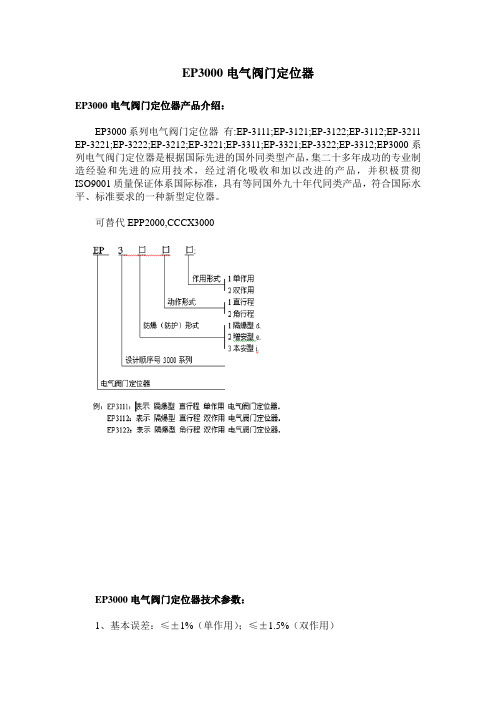
EP3000电气阀门定位器EP3000电气阀门定位器产品介绍:EP3000系列电气阀门定位器有:EP-3111;EP-3121;EP-3122;EP-3112;EP-3211 EP-3221;EP-3222;EP-3212;EP-3221;EP-3311;EP-3321;EP-3322;EP-3312;EP3000系列电气阀门定位器是根据国际先进的国外同类型产品,集二十多年成功的专业制造经验和先进的应用技术,经过消化吸收和加以改进的产品,并积极贯彻ISO9001质量保证体系国际标准,具有等同国外九十年代同类产品,符合国际水平、标准要求的一种新型定位器。
可替代EPP2000,CCCX3000EP3000电气阀门定位器技术参数:1、基本误差:≤±1%(单作用);≤±1.5%(双作用)2、回差:≤1% (单作用);≤1.5% (双作用)3、死区:≤0.2%(单作用);≤0.4%(双作用)4、额定行程:0-(10-100)mm。
[角行程(转角行程)0-(50°-90°)5、气源压力:0.14-0.7Mpa6、输入信号:4-20MA.DC(标准型、常规产品)(4-12MA.DC、12-20MA.DC)0-10MA.DC[变形产品](0-5MA.DC、5-10MA.DC)7、输出压力:0.02-0.7Mpa8、耗气量:单作用执行器:5L/min(供气0.14Mpa);双作用执行器:15L/min(供气0.4Mpa)9、输出特性:线性常规型;(等百分比、非线性特殊型)10、环境温度:-35-+60°c(本质安全型为-20- +60°C)11、相对湿度:5%-100%12)防爆(防护)型式(等级):隔爆型d(Diibt6),增安型e(Eiit6),本质安全型i(iaIICT6)13、输入阻抗:4-20.MA.DC/250?±5%(20°C时)14、外壳材料:铝合金喷朔工艺处理15、外形尺寸:205*192*78(mm)(长*宽*高)16、重量:2.1kgEP3000电气阀门定位器产品特点:1、兼容互换性好,适用范围广。

Accredited CalibrationQuality at EMC PARTNER is based on an ISO 9001 manage-ment system. This is the foundation for an ISO 17025 accredi-tation verified by the Swiss Calibration Service (SCS). SCS No. 146 is the accreditation number of EMC PARTNER AG. Locally accredited but recognized worldwide through affiliation with the ILAC organisationTHE ESD TESTING SOLUTIONPOWER AT YOUR FINGER TIPSElectrostatic Discharge (ESD) is the most common test procedure applied toany electronic or electrical equipment. Used extensively to test:›Commercial products›Industrial systems›Military electronics›Automotive electronics›Fuses and detonators›Railway electronics›Avionic equipment qualification›Telecom equipment›Electronic componentsThe easily changeable and fully calibrated discharge networks, quickly adaptESD3000 to the requirements of any new application.Light and easy to use.3EASIL Y EXPANDABLEESD3000 is designed with the user in mind. The modular design allows configuration ac -cording to customer wishes, addition of more networks when adding applications and easy extension from 16kV to 30kV using the same generator. Automatic network recognition means ESD3000 is always ready.ESD3000 + DMx ESD3000 + RM32 + DNxIncludedRechargable Long-life battteriesUp to 3 test tips (Sharp, Round, Corona)Charger & Firmware update cableHandy, robust carrying case4Discharge Modules (DMx)up to 16kV Air / 10kV Contact Discharges ESD3000 required Discharge Networks (DNx)up to 30kV Air- and Contact Discharges DM1 (150pF, 330 Ohm)DM2 (330pF / 2000 Ohm)DM4 (100pF / 1500 Ohm)DM6 (100pF / 1500 Ohm)DM7 (200pF / 0 Ohm)ESD3000 & RM32 required DN1 (150pF / 330 Ohm)DN2 (330 pF, 2000 Ohm)DN3 (150 pF, 2000 Ohm)DN4 (500 pF, 5000 Ohm)DN5 (500 pF, 500 Ohm)DN6 (330 pF, 330 Ohm)Available Extensions Available ExtensionsAVAILABLE MODULESCommercial & IndustrialIEC 61000-4-2 / ITU-T K.44ESD3000DM1 (150pF, 330 Ohm)ANSI / IEEE C63.16ESD3000 DM16A-C63H (150pF / 330 Ohm)ESD3000 DM16C-C63H (150pF / 330 Ohm)UL 991ESD3000DM32A-UL991 (100pF / 1000 Ohm)Component TestIEC 61340-3-1 / JEDEC 22-A114 / MIL-STD-750DESD3000DM6 (100pF / 1000 Ohm)IEC 61340-3-2 / JEDEC 22-A115ESD3000DM7 (200pF / 0 Ohm)AutomotivePSA B21 7110ESD3000DM2 (330pF / 2000 Ohm)ISO 10605 / SAEJSSI-IS/FORD AB/AC /GMW 3097ESD3000DN1(150pF / 330 Ohm)ESD3000DN2 (330pF / 2000 Ohm)ESD3000DN3 (150pF / 2000 Ohm)ISO 10605ESD3000DN6 (330pF / 330 Ohm)JASO D 001-94ESD3000DN32-CAR1 (150pF / 500 Ohm)Renault 32-10-001/D and 32-10-035/AESD3000DN32-CAR5 (330pF / 0 Ohm)MilitaryMIL-STD-883 / GR78-COREESD3000DM4 (100pF / 1500 Ohm)STANAG 4239 / ISO 14304 / MIL-STD-1512ESD3000DN4 (500pF / 5000 Ohm)MIL-STD-331C / MIL-DTL-23659D / STANAG 4239ESD3000DN5 (500pF / 500 Ohm)MIL-STD-1576ESD3000DN32-MIL2 (400pF / 150 Ohm)ESD3000DN32-MIL3 (500pF / 0 Ohm)5The original 30kV battery powered generator with a unique system of changeable modules. Flexibility and power combined.UNIQUE FEATURES Long life standard battery. Up to 8 hours on full battery charge. Readily available in any store.AA battery powered Add calibrated modules to maintain the system value. Unique modules and accessories for special applications. Extend testing capability Single key press switches polarity before and during the test.Electronic polarity changeErgonomic hand held tester without additional base unit. Program directly on generator.Compact solution6Technical Specifications7ESD3000 MODULES ESD3000M a i n f r a m e D M 1D M 2D M 4D M 6D M 7R M 32D N 1D N 2D N 3D N 4D N 5D N 6C A R 1C A R 5I N D 1M I L 2M I L 3A -C 63HC -63H U L 991IEC 61000-4-2✓✓✓ITU-T K20✓✓PSA B32 7110✓✓MIL-STD-883✓✓GR78-CORE ✓✓IEC 61340-3-1✓✓JEDEC 22-A114✓✓MIL-STD-750D ✓✓IEC 61340-3-2✓✓JEDEC22-A115✓✓✓ISO 10605✓✓✓✓✓✓DO-160 S25✓✓✓✓MIL-STD-461G CS118✓✓✓✓ GMW3100✓✓✓✓✓✓GMW3097✓✓✓✓STANAG4239✓✓✓✓ISO14304✓✓✓MIL-STD-1512✓✓✓✓MIL-STD-330C ✓✓✓✓JASO D 001-94✓✓✓Renault 32-10-001/D ✓✓ABD0100.1.2✓✓✓Special MIL ✓✓✓MIL-STD-1576✓✓✓ANSI C63.16✓✓✓UL991✓8ACCESSORIES FOR DIFFERENT MODULES ESD3000M a i n f r a me D M 1D M 2D M 4D M 6D M 7R M 32D N 1D N 2D N 3D N 4D N 5D N 6C A R 1C A R 5I ND 1M IL 2M IL3A -C 63HC -63HEARTH CABLE ✓IEC IECESD-VCP50✓IEC IECESD-TARGET2✓IECESD-TARGET2 DN ✓ISO ISO ISO ISOESD-VERI-V ✓✓O O O ✓O O ✓✓O O O ✓✓✓✓ESD-STAND ED2✓O O O O O O O O O O O O O O O O O O O ESD-HCP-AUTO ✓ISO ISODM-EXT ✓MIL MILSAFETY-S ✓MIL MILTC-MIG24 ED ✓MIL MILESD3000 CNH12✓O O O O O OOPTOLINK ✓O O O O O O O O O O O O O O O O O O O TEMA ✓O O O O O O O O O O O O O O O O O O O Overview ESD3000 | Modules | Accessories 91. ESD3000 MAINFRAME AND MODULES1.1. TECHNICAL SPECIFICATIONS ESD3000 MainframeTo be used with modules all modules from this document are compatible Construction fully portable, no additional basic unitControl LCD and 6 menu buttons, 1 trigger button Maximum voltage 16 kV or 30 kV, depending on modules chosen Voltage steps 100 V - testDischarge polarity positive, negative, alternatingDischarge modes contact discharge (CD) and air discharge (AD)Discharge frequency CD max. 20 Hz, (pulse every 0.05, 0.1, 0.2 … 99 s)Discharge frequency AD ≥ 30 Hz or more, for ex. with DM1, DN1, other Counter pre-selectable, 1 to 29999Discharge detection selectable, count pulses or count discharges Holding time ≥ 5 sTrigger manual, automatic, remote Ramps voltage, polarityReporting with TEMA automatic report sequence, amplitude,polarity Dimensions for ex. withDM1 and tip 340 x 130 x 70 mm Weight mainframe 730 g, w/o battery pack and module Weight equipped 1050 g, with battery pack, DM1 and AD tip Power supply 10 x AA rechargeable batteries or mainsIncluded 10 batteries, mains adapter, ground cable 2 m, 3 test tips (AD, AD2, CD), carrying case, RS232 cable, E3Loader for remote control Requires at least a DM module, or a DN module + RM32ESD3000DM1Standards IEC 61000-4-2 (latest), ITU-T K.20,Other standards MIL-STD-461G CS118, DO-160 Section 25Storage capacitor 150 pF ± 10 %Discharge resistor 330 Ω ± 10 %Voltage range AD 0.2 – 16 kV ± 5 %Voltage range CD 0.2 – 10 kV ± 5 %Current rise time into 2 Ω0.8 ± 25 %First I peak into 2 Ω CD 7.5 A @ 2 kV – 37.5 A @ 10 kV (± 15 %)Current at 30 ns 4 A @ 2 kV – 20 A @ 10 kV (± 30 %)Current at 60 ns 2 A @ 2 kV – 10 A @ 10 kV (± 30 %)Optional ESD-TARGET2Overview ESD3000 | Modules | Accessories10ESD3000DM2Standards PSA B32 7110 up to 16 kV / 10 kVStorage capacitor330 pF ± 10 %Discharge resistor2000 Ω ± 10 %Voltage range AD0.2 – 16 kV ± 5 %Voltage range CD0.2 – 10 kV ± 5 %Current rise time into 2 Ω0.7 – 1 nsFirst I peak into 2 Ω CD7.5 – 30 A ± 10 %RC time constant600 ± 130 nsESD3000DM4Standards MIL-STD-883, GR78-COREStorage capacitor100 pF ± 10 %Discharge resistor1500 Ω ± 10 %Voltage range AD0.2 – 16 kV ± 5 %Voltage range CD0.2 – 10 kV ± 5 %Current rise time into 2 Ω<********–8kVI peak into 2 Ω (CD) 2.66 A @ 4 kV, 3.33 A @ 5 kVESD3000DM6Standards IEC 61340-3-1, JEDEC 22-A114,MIL-STD-750DStorage capacitor100 pF ± 10 %Discharge resistor1500 Ω ± 10 %Voltage range CD0.25 – 8 kV ± 10 %Current rise time into 2 Ω2–*********–8kVRC time constant150 ± 20 nsESD3000DM7Standards IEC 61340-3-2, JEDEC 22-A115Storage capacitor200 pF ± 10 %Discharge resistor0 Ω ± 10 %Voltage range CD0.1 – 2 kV ± 5 %Current into short circuit 1. 7 A – 35 A ± 15 % into short circuit (< 1 Ω)Current waveform as per IEC 61340-3-2 into SC (< 1 Ω)Current ringing frequency11 – 16 MHz @ 0.1 – 2 kV into SC (< 1 Ω)ESD3000DM32A-UL991Standard UL991, paragraph 15.2.2Storage capacitor100 pF ± 10 %Discharge resistor1500 Ω ± 5 %Discharge mode AD only, consists of DM+ and DM- modulesVoltage range AD 4 – 30 kV ± 5 %Rise time at 4 kV, 20 kV< 5 nsRC const. at 4 kV, 20 kV150 ns ± 20 %Overview ESD3000 | Modules|Accessories1130 KVThese Extensions need the Module ESD3000RM32ESD3000DN1Standards IEC 61000-4-2,ISO 10605Other standards MIL-STD-461G CS118, DO-160 Section 25Storage capacitor150 pF ± 10 %Discharge resistor330 Ω ± 10 %Voltage range AD 1 – 32 kV ± 5 %Voltage range CD 1 – 30 kV ± 5 %Current rise time into 2 Ω0.8 ± 25 %First I peak into 2 Ω CD7.5 A @ 2 kV – 112.5 A @ 30 kV (± 15 %)Current at 30 ns 4 A @ 2 kV – 60 A @ 30 kV (± 30 %)Current at 60 ns 2 A @ 2 kV – 30 A @ 30 kV (± 30 %)Requires ESD3000RM32Included in ESD3000RM32Detachable module for faster tr (<700ps)Optional ESD-TARGET2 DN, ESD-HCP-AUTOESD3000DN2Standards ISO 10605, GMW3100, GMW3097Storage capacitor330 pF ± 10 %Discharge resistor2000 Ω ± 10 %Voltage range AD 2 – 30 kV ± 5 %Voltage range CD 2 – 30 kV ± 5 %Current rise time into 2 Ω0.7 – 1 nsFirst I peak into 2 Ω CD7.5 A @ 2 kV – 112.5 A @ 30 kV (- 0 / + 30 %) RC time constant600 ± 130 nsRequires ESD3000RM32Optional ESD-TARGET2 DNESD3000DN3Standards ISO 10605, GMW3100, GMW3097Storage capacitor150 pF ± 10 %Discharge resistor2000 Ω ± 10 %Voltage range AD 2 – 30 kV ± 5 %Voltage range CD 2 – 30 kV ± 5 %Current rise time into 2 Ω0.7 – 1 nsFirst I peak into 2 Ω CD7.5 A @ 2 kV – 112.5 A @ 30 kV (- 0 / + 30 %) RC time constant300 ± 60 nsRequires ESD3000RM32Optional ESD-TARGET2 DNOverview ESD3000 | Modules|Accessories12ESD3000DN4Standards STANAG4239, ISO14304MIL-STD-1512, MIL-STD-330Storage capacitor500 pF ± 10 %Discharge resistor5000 Ω ± 10 %Voltage range CD 2 – 30 kV ± 5 %I rise time into 2 Ω CD0.7 – 1 nsRequires ESD3000RM32Optional ESD3000 SAFETY-S, DM-EXT,TC-MIG24EDESD3000DN5Standards STANAG4239, MIL-STD-1512, MIL-STD-330Storage capacitor500 pF ± 10 %Discharge resistor500 Ω ± 10 %Voltage range CD 2 – 30 kV ± 5 %I rise time into 2 Ω CD0.7 – 1 nsRequires ESD3000RM32Optional ESD3000 SAFETY-S, DM-EXT,TC-MIG24EDESD3000DN6Standards ISO 10605, GMW3100Storage capacitor330 pF ± 10 %Discharge resistor330 Ω ± 10 %Voltage range AD 2 – 30 kV ± 5 %Voltage range CD 2 – 30 kV ± 5 %Current rise time into 2 Ω0.7 – 1 nsRC time constant300 ± 130Requires ESD3000RM32Optional ESD-TARGET2 DN, ESD-HCP-AUTOSPECIALESD3000DN32-CAR1Standard JASO D 001-94Storage capacitor150 pF ± 10 %Discharge resistor500 Ω ± 10 %Voltage range AD 2 – 30 kV ± 10 %Voltage range CD 2 – 30 kV ± 10 %I rise time into 2 Ω CD0.8 ± 25 %First I peak into 2 Ω AD< 5 nsRC time constant300 ± 60 nsRequires ESD3000RM32Optional ESD-TARGET2 DNOverview ESD3000 | Modules|Accessories13ESD3000DN32-CAR5Standard Renault 32-10-001/DApplication testing airbag initiatorsStorage capacitor330 pF ± 10 %Discharge resistor0 Ω ± 10 %Source impedance Rt< 30 ΩVoltage range AD 2 – 16 kV ± 5 %Voltage range CD 2 – 16 kV ± 5 %Requires the module is already integrated in RM32 ESD3000DN32-IND1Standard ABD0100.1.2, IEC801-2Storage capacitor150 pF ± 10 %Discharge resistor150 Ω ± 10 %Voltage range AD 2 – 30 kV ± 5 %Voltage range CD 2 – 30 kV ± 5 %I rise time into 2 Ω CD0.7 – 1 nsRC time constant30 ns ± 30 %Requires ESD3000RM32ESD3000DN32-MIL2Standards special military requirementStorage capacitor400 pF ± 10 %Discharge resistor150 Ω ± 10 %Voltage range AD 2 – 30 kV ± 5 %Voltage range CD 2 – 30 kV ± 5 %I rise time into 2 Ω CD0.8 ± 25 %Requires ESD3000RM32ESD3000DN32-MIL3Standard MIL-STD-1576Storage capacitor500 pF ± 10 %Discharge resistor0 Ω ± 10 %Voltage range CD 2 – 30 kV ± 5 %Requires ESD3000RM32ESD3000DM16A-C63HStandard ANSI C63.16 (AD requirement)Storage capacitor150 pF ± 10 %Discharge resistor330 Ω ± 10 %Voltage range AD 2 – 16 kV ± 5 %Requires-Overview ESD3000 | Modules|Accessories14ESD3000DM16C-C63HStandard ANSI C63.16 (CD requirement)Storage capacitor150 pF ± 10 %Discharge resistor330 Ω ± 10 %Voltage range CD 2 – 16 kV ± 5 %Requires-1.2. POWER, CLIMATIC CONDITIONS, SHIPPING WEIGHT, DIMENSIONSESD3000 mainframeMains adapter95 – 250 V (50/60 Hz)Power consumption ON < 20 VA, standby < 5 VATemperature range15 – 35 °CHumidity30 – 60 % non-condensingAir pressure86 – 106 kPaShipping weight 2.4 kg plus selected modulesCarrying case dimensions46 x 41 x 17 cmIncluded in deliveryUser manual with conformity declarationCalibration certificate factory calibration for selected modules2. ACCESSORIES FOR ESD30002.1. TECHNICAL SPECIFICATIONSEARTH CABLEApplication connection of HCP or VCP to ground planeImpedance 2 x 470 kΩLength 2 mConnectors 2 x banana plugsOverview ESD3000 | Modules|Accessories15ESD-VCP50Application indirect ESD application as per standardSpacer in between10 cm wooden spacerCoupling plane50 x 50 cmApplication points one on each sideDimensions50 x 50 x 10 cmWeight8 kgIncluded 2 m earth cable (with 2 x 470 kΩ)ESD-TARGET2Standard IEC 61000-4-2 latestApplication current target for calibration of ESD generator Input impedance 2 ΩInput voltage max. 10 kV CDFrequency range± 0.5 dB up to 1 GHz, ± 1.2 dB up to 4 GHzCurrent range0 – 50 A standard, could be extendedTransfer function0.2 V / 1 A with 20 dBDiameter70 mmThickness40 mmWeight398 g including attenuatorFixing8 x M3 screws, included in deliveryIncluded20 dB att., 50 Ω coax. cable (1 m) with BNC out ESD-TARGET2 DNStandard IEC 61000-4-2 latestApplication current target for calibration of ESD generator Input impedance 2 ΩInput voltage max. 30 kV CDFrequency range± 0.5 dB up to 1 GHz, ± 1.2 dB up to 4 GHzCurrent range0 – 120 A standard, could be extendedTransfer function0.2 V / 1 A with 20 dB, 0.02 V / 1 A with 40 dB Diameter70 mmThickness40 mmWeight398 g including attenuatorFixing8 x M3 screws, included in deliveryIncluded40 dB att., 50 Ω coax. cable (1 m) with BNC out ESD-VERI-VApplication target for ESD DC voltage measurementInput impedance20 GΩ || 3 pFInput voltage range0 – 32 kVOutput voltage range0 – 1.6 VOutput connector BNCDimensions17 cm height, 5.5 cm diameterWeight433 gIncluded earth conductorOverview ESD3000 | Modules|Accessories16ESD-STAND Ed2Application stand for supporting ESD gun, fixed point testHeight50 – 180 cm, adjustablePosition360˚ adjustableDimensions64 x 17 x 12 cm (packed)Weight 4 kgIncluded cable holder for calibrationESD-HCP-AUTOApplication coupling plane as per ISO 10605 annex FLength1500 mmInsulation distance50 mmTest level8 – 20 kV, as per standardDimensions180 x 120 x 5 cmWeight 2.2 kgIncluded EARTH CABLEESD3000DM-EXTApplication 1 m extension cable for ESD3000 modulesCompatibility DM and DN modulesCable length 1 ± 0.05 mWeight0.5 kg including accessoriesCan be used with DN modulesESD3000 SAFETY-SStandard MIL-STD-1512Application safety switch for testing explosive devicesVoltage max. 30 kV CDDimensions20 x 16 x 12 cmWeight 2 kg including accessoriesIncluded mains adapterTo be used with ESD3000DM-EXT, TC-MIG24 EDTC-MIG24 ED for testing explosive devicesApplication test cabinetVoltage insulation max. 36 kVEUT dimensions max. 30 x 30 x 20 cmEUT weight max. 5 kgSafety circuit door interlockSignal lamps red and green lamps built-inControl of signal lamps for example with ESD3000 SAFETY-SDimensions47 x 43.5 x 25.4 cmWeight8 kgIncluded connection cable 25pol/ESD3000 SAFETY-SOverview ESD3000 | Modules|Accessories17ESD3000 CNH12Application Magnetic field loop for ESD3000 test system Loop diameter12 cmLoop current allowed> 100 ADischarge mode selection contact discharge (CD)Current at 15 kV setting50 A, with RM32 and DN1Current at 30 kV setting108 A, with RM32 and DN1Dimensions33 x 13 x 1 cmWeight0.2 kg including accessoriesRequires ESD3000RM32, ESD3000DN1or other DNESD3000-OPTOLINKApplication(insulating) optical cable ESD3000 - computer Length10 mInterface RS232, requires USB adapterBaud rate9600 bpsWeight0.2 kgIncluded tranceiver with mains adapterRequires USB-RS 232 ADAPTERUSB-RS232 ADAPTERApplication adapter between RS232 and USB interfac-esAdapter type Passive, no power supplyInput RS232 maleOutput USBCable length0.35 mWeight0.2 kgTEMAApplication control software for ESD3000 systemLicense 1 license for 1 generatorCapabilities with ESD3000Sequences, reporting, remote controlCompatibility Windows XP, 7, 8, 10Requires ESD3000-OPTOLINK, USB-RS 232 ADAPTEROverview ESD3000 | Modules|Accessories18THE EMC PARTNER PRODUCT RANGE Find further brochures on our website /brochures or contact your local representative for a hardcopy.LIGHTNING TESTSImpulse test equipment and accessories for aircraft, military and tel -ecom applications. Complete solutions for RTCA / DO-160 and EURO -CAE / ED-14 for indirect lighting on aircraft systems, MIL-STD-461 tests CS106, CS115, CS116, CS117, CS118 and Telecom, ITU-T .K44 basic and enhanced tests for impulse, power contact and power induction.COMPONENT TESTSImpulse generators for testing; varistors, gas discharge tubes (GDT),surge protective devices (SPDs), X / Y capacitors, circuit breakers,electricity meters, protection relays, insulation material, suppressor diodes, connectors, chokes, fuses, resistors, emc-gaskets, cables, etc. EMISSION MEASUREMENTSMeasurement of Harmonics and Flicker in 1-phase and 3-phaseelectrical and electronic products according to IEC /EN 61000-3-2 and 61000-3-3 . HARCS Immunity software adds interharmonic tests, voltage variation according to IEC/EN 61000-4-13, -4-14.IMMUNITY TESTSTransient Test Systems for all EMC tests on electronic equipment. ESD, EFT, surge, AC dips, AC magnetic field, surge magnetic field, commonmode, damped oscillatory and DC dips. According to IEC and EN 61000-4-2, -4, -5, -8, -9, -10, -11, -12, -13, -14, -16, -18, -19, -29.SYSTEM AUTOMATIONA full range of accessories enhance the test systems. Test cabinets, test pistols, adapters and remote control software, simplify interfacing with the EUT. Programmable PSU, EMC hardened for frequencies from 16.7Hz to 400Hz. PS3-SOFT-EXT complies with IEC / EN 61000-4-14 and -4-28.SERVICEOur committment starts with a quality management system backing up our ISO 17025 accreditation. With the SCS number 146, EMC PARTNERprovide accredited calibration and repairs. Our customer support teamare at your service!。

Dedicated designed for High Voltage and High Current application• On wafer high power devic e measurement up to 10 kV/600 A• Gold plated c huc k surface for minimum contac t resis-tance and vacuum holes optimized for thin wafer hand-ling down to 50 µm• Taiko wafer chuck option• Dedicated high voltage and high current probes • Anti-arcing solutionsMPI ShieldEnvironment™ for Accurate Measurements • Designed for Advanced EMI / RFI / Light-Tight Shielding • fA low-leakage capabilities• Ready for temperature range -60 °C to 300 °CErgonomic Design and Safety• Easy wafer or single DUT loading from the front• Regulatory approved safety interlocked light curtain to protect users• Integrated active vibration isolation• Completely integrated prober c ontrol for faster, safer and c onvenient system and test operation• T he Safety Test Management (STM™) option to load/unload wafers at any chuck temperatures and auto dew point controlMPI TS3000-HP | 300 mm Automated Probe SystemFor accurate and reliable High Power measurementsFEATURES / BENEFITSSTAGE SPECIFICATIONSMax. movement speed 50 mm / secChuck Z Stage (Programmable)Travel range 30 mm (1.18 in)Resolution 0.2 µm Accuracy ± 2 µm Repeatability ± 1 µmZ stage drive Closed-loop high precision stepper motor GuiderPrecision ball bearingsPROBE PLATENMICROSCOPE MOVEMENTSTAGE SPECIFICATIONSChuck Theta Stage (Programmable)Travel range ± 5.0°Resolution 0.0001° (0.24 µm @ 300mm edge)Accuracy < 2.0 µm (measured at the edge of the 300 mm chuck)Repeatabilty < 1.0 µmTheta stage driveHigh resolution stepper motor with linear encoder feedback systemLarge Probe Platen supporting up to 8x DC or 4x DC + 4x RF MicroPositioners or standard 4.5” probe card holderXYZ Programmable XY - Travel range*50 x 50 mm / 300 x 300 mm Resolution 1 µm (0.04 mils)Repeatability ≤ 2 µm (0.08 mils)Accuracy ≤ 5 µm (0.2 mils)Z - Travel range 140 mmResolution 0.05 µm (0.002 mils)Repeatability ≤ 2 µm (0.08 mils)Accuracy≤ 4 µm (0.16 mils)*In case of ShielDEnvironment™ X x Y: 25 mm x 25 mmShielDEnvironment™MPI ShielDEnvironment™ is a high performance local environmental chamber providing excellent EMI- and light-tight shielded test environment for ultra-low noise, low capacitance measurements.MPI ShielDEnvironment™ allows up to 4-port RF or up to 8-ports DC/Kelvin or a combination of those configu-rations. MPI ShielDCap™ provides easy reconfiguration of measurement setup as well as EMI/noise shielding - which make great difference in simplifying day to day operations.ShielDEnvironment™ Electrical Specifications*EMI shielding> 30 dB (typical) @ 1 kHz to 1 MHzLight attenuation≥ 130 dBSpectral noise floor≤ -180 dBVrms/rtHz (≤ 1 MHz)System AC noise≤ 5 mVp-p (≤ 1 GHz)*Including 4 MicroPositioners.SAFETY MANAGEMENTLight CurtainLight Curtain Interloc k protec ts user from ac c identalhigh voltage shoc k by shutting down the instrumentthrough interlock system. The interlock system at reardoors provides safety, easy and convenient initial mea-surement set-up.WAFER LOADINGLoading or unloading of 150, 200 or 300 mm wafers or substrates is straight forward and intuitive. Special design of the chuck provides easy loading of a single IC of wafer fragments from the system front. SmartVacuum TM tech-nology automatically recognizes size of the wafer on single IC. It also protects the wafer from unexpected release of vacuum due to inexperienced operation when the wafer is located in the IceFreeEnvironment TM.Easy access to the AUX chucks serves for quick exchange of RF calibration substrates, probe cleaning and plana-rization accessories.Probe Hover Control™MPI Probe Hover Control PHC™ allows easy ma-nual c ontrol of probe c ontac t and separation to wafer. Separation distance can accurately control with micrometer feedback for probe to wafer/pad positioning. Ease of use guarantees the safest operation by minimizing error during critical set-up and probe change operations.THERMAL CHILLER INTEGRATIONPicture is courteously provided by ERS.Minimized CDA ConsumptionThe CDA consumption is reduc ed by as muc h as 50% by purging IceFreeEnvironment TM with the re-used cold air of the chiller. Additional automated valve enables purge by Nitrogen*.Additionally, recycled CDA cools the system probe platen and the probe card.*ERS patented technology.Thermal chuck touchscreen control display is an alternative way of interaction with the thermal system. Its ergo-nomic location supports an operator when keying commands and monitoring system status. The fully integrated intelligent hardware control panel is design for intuitive and safe system control and operation. All these signifi -cantly increase the speed and improve convenience of the system interaction work flow.The keyboard and mouse are placed on the sliding tray right below the system control panel. Both can control test instrumentation, if required.USB port is also in front of the system. It removes any hassles when exchanging data.INTEGRATED CONTROLSUnique and revolutionary multi-touch operation soft -ware SENTIO® controls MPI automated engineering pro-be systems. Its simple and intuitive operation c onc ept significantly saves operator training time. Scroll, Zoon, and Move functions mimic modern smart mobile device interface. Switching between applications is just a mat-ter of a simple finger swipe.SENTIO® makes everyone the system operation expert in just minutes.SOFTWARE SOLUTIONHigh Voltage Probes (HVP)Low leakage probes spec ially designed to withstand high voltage up to 10 kV (c oaxial) and 3 kV (triaxial). Choice of various connectors options such as Keysight Triax/UHV, Keithley Triax/UHV, SHV or Banana.High Current Probe (HCP)High performance probes specially designed for on wa-fer measurement of high c urrent up to 200 A (pulse). MPI multi-fingers high current probes are single piece consturction to efficiently handle high current and pro -vide low contact resistance.HIGH POWER PROBESHIGH POWER PROBES - SELECTION GUIDE[2]Keysight or Keithley [3]Banana: 100 A max, 1 ms max PW, 1% max PLC [4]BNC: 40 A max, 1 ms max PW, 1% Max PLCUltra High Power Probe (UHP)Designed for Ultra high voltage and c urrent on wafer measurement up to 10 kV/600 A (pulse). MPI replaceable multi-fingers probes tips and probe arms are design for low contact resistance for ultra-high current measure-ment and to support ultra-high voltage of up to 10 KV, without having to change probes for high voltage and current application.UL TRA HIGH POWER PROBESHigh current probe1 finger4 fingers6 fingers8 fingers12 fingersMax current*20 A 80 A120 A 160 A 250 A Max voltage10 KV 10 KV 10 KV 10 KV 10 KV Residual resistance (Typical)≤ 5 mΩ≤ 3 mΩ≤ 1 mΩ ≤ 1 mΩ≤ 1 mΩConnector options Banana Banana Banana Banana Banana Replaceable tip Yes Yes Yes Yes Yes Probe tip width 250 µm 250 µm 250 µm 250 µm 250 µm Probe pitch--650 µm650 µm650 µm650 µm*1 ms Max PW, 0.4% max PLCUL TRA HIGH POWER PROBES - SELECTION GUIDEDIMENSIONSUltra High Power probeOptional Anti-Arcing Probe CardIn addition, MPI is offering optional temperature control of the pressurized air in a range of 20 to 200 °C, which correlate direct with the chuck set temperature.High-voltage testing without arcing at higher tempera-tures are possible now.ANTI-ARCING SOLUTIONSOptional Anti-Arcing LiquidTray™Specially designed anti-arcing LiquidTray™ can be used for arcing suppressing by simply place on the high power chuck surface. Wafers can be safely placed inside the tray to submerge in the liquid for arcing free high voltage test.High Power Wafer ChucksConnectivity 110 kV Coaxial (Banana or SHV)Connectivity 2Kelvin Triax (f), 3 kV or 10 kV CoaxialDiameter310 mm with 2 integrated AUX areasMaterial Gold plated aluminum (flat with 100 µm holes)Chuck surface Planar with 0.5 mm diameter holes in centric sectionsVacuum holes sections (diameter)4, 24, 48, 72, 96, 120, 144, 168, 192, 216, 240, 264, 288 mm SmartVacuum™ distribution In front for single DUT 5x5 mm (4 holes) and 75 mm (3 in) In center for150, 200, 300 mm (6, 8, 12 in)Supported DUT sizes Single DUTs down to 5x5 mm size or wafers 100 mm (4 in) thru 300 mm(12 in)*Surface planarity≤± 5 µmRigidity< 15 µm / 10 N @edge*Single DUT testing requires higher vacuum conditions dependent upon testing application.NON-THERMAL HIGH POWER CHUCKSElectrical Specification (Triax)Chuck isolation> 30 TΩForce to guard> 30 TΩGuard to shield> 500 GΩForce to shield> 100 GΩMPI Non-thermal Triaxial High Power Chuc k with goldplated surface for low contact resistanceMPI 10 kV Triaxial Connector used for Kelvin chuck connectionHIGH POWER THERMAL CHUCKSSpecifications TC-300N Power TC-300NT Power TC-300NT ULN PowerCooling rates** (faster with -60 °C chiller)AC3 Mode25 to -10 °C< 11 min< 12 min< 18 min25 to -40 °C< 18 min< 20 min< 28 min25 to -60 °C< 36 min< 40 min< 66 min200 to 35 °C< 24 min< 27 min< 35 min200 to 20 °C< 28 min< 30 min< 40 min300 to 35 °C N/A N/A< 41 min300 to 20 °C N/A N/A< 54 minTURBO Mode25 to -10 °C< 11 min< 12 min< 18 min25 to -40 °C< 16 min< 18 min< 27 min25 to -60 °C< 34 min< 37 min< 65 min200 to 35 °C< 24 min< 27 min< 35 min200 to 20 °C< 28 min< 30 min< 40 min300 to 35 °C N/A N/A< 41 min300 to 20 °C N/A N/A< 54 minTYPICAL TRANSITION TIME102030405060708090100-100-50050100150200250300350time [min]t e m p e r a t u r e [°C ]MPI & ERS AirCool PRIME RF Chuck -60°C to +300°CMPI & ERS AirCool PRIME RF Chuck +20°C to +300°C5101520253035404550556065050100150200250300350time [min]t e m p e r a t u r e [°C ]102030405060708090100110-100-50050100150200250300350t e m p e r a t u r e [°C ]time [min]MPI & ERS AirCool PRIME Ultra Low Noise Chuck -60°C to +300°C510152025303540050100150200250300350t e m p e r a t u r e [°C ]time [min]MPI & ERS AirCool PRIME Ultra Low Noise Chuck +20°C to +300°CLeakage@ Voltage and:10 V 1.1 kV 10 V 3 kV 10 V 3 kV 10 kV @ -60 °C < 2 pA < 220 pA < 300 fA < 100 pA < 30 fA < 10 pA < 6 nA @ 25 °C < 1 pA < 110 pA < 150 fA < 50 pA < 15 fA < 5 pA < 6 nA @ 200 °C < 1 nA < 110 nA < 300 fA < 150 pA < 30 fA < 10 pA < 15 nA @ 300 °CN/AN/AN/AN/A< 50 fA < 15 pA < 40 nACapacitanceForce-to-Guard < 1600 pF < 600 pF < 600 pF ** Typical values, depends on chiller type and facility supply, please check MPI FPS for the certain chuck and system.300 mm PRIME High-Power Chuck -10°C to +300°CERS AirCool® Fusion*, Controller Integrated Chiller -40 °C / -60 °C ERS AirCool® Fusion*, ControllerIntegrated Chiller -10 °CERS High Power Thermal Chuck*ERS electronic GmbH patented solutionTS3000-HP can be configured with instrument connection package. The packages consists of necessary high voltage/high current probes and cabling accessories for optimal connection to the test instruments. Keysight B1505AHigh Power chuck shorting and floating plugs Keithley 2600-PCT-XB INSTRUMENT CONNECTION PACKAGESExample of Keysight B1505A and Keithley 2600-PCT-XB connection panels.REGULATORY COMPLIANCE WARRANTY• Warranty*: 12 months• Extended service contract: contact MPI Corporation for more information*See MPI Corporation‘s Terms and Conditions of Sale for more details.3rd party, TÜV tested according to • IEC 61010-1: 2010 + Am1:2016; EN 61010-1: 2010; IEC/EN 61010-2-010: 2014; IEC/EN 61010-2-081: 2015; EN ISO 12100: 2010; UL 61010-1: 2012/R: 2016-04; UL 61010-2-010: 2015; CAN/CSA-C22.2 No. 61010-1: 2012/U2: 2016-04; CAN/CSA-C22.2 No. 61010-2-010:2015and certified for CE and US/Canada (NRTL), SEMI S2 and S8.Copies of certificates are available on requestFACILITY REQUIREMENTSSYSTEM CONTROLLER SPECIFICATIONSSUPPORTED SOFTWARE PLATFORMSGeneral Probe SystemPower100-240 V AC nominal ; 50/60 Hz Vacuum-0.9 bar Compressed air 6.0 barCPUIntel® Core TM i7-7700, 3.6 GHz, 8M Cache, 14nm, 65W TDP, LGA1151(4C/8T)RAMDDR4 2400 MHz 16 GB x 164 bit operating systemWindows 10 Professional (English)Power460 W StorageSSD 500 GB LANOne internal and one external TCP/IP ports USB PortsInternal (on PC) x3, external x1GPIB interface OptionalDriversWaferPro / IC-CAP & EasyEXPERT from Keysight, BSIMPro & NoisePro from ProPlus, ACS from Keithley Emulation mode Available for various prober control software** Please contact your local support for more details.MPI Global PresenceDirect contact:Asiaregion:****************************EMEAregion:******************************Americaregion:********************************MPI global presence: for your local support, please find the right contact here:/ast/support/local-support-worldwide© 2022 Copyright MPI Corporation. All rights reserved.PHYSICAL DIMENSIONSTS3000-HPSystem Dimensions (W x D x H)1400 x 1300 x 1700 mm (55.1 x 51.2 x 66.9 in)Weight960 kg*Can vary depends on monitor/chiller position.。
Programat®EP 3000操作使用说明目录瓷炉概览,部件列表 41. 介绍 / 标识和符号 81.1 前言1.2 说明1.3 操作注意事项2. 安全守则 92.1 适用范围2.2 健康和安全指导3. 产品描述 123.1 部件3.2 危险区域和设备安全3.3 功能描述3.4 配件4. 安装和初始运行 134.1 卸货检查物件4.2 选择放置点4.3 装配4.4 取出瓷炉盖4.5 初启动5. 操作和配置 195.1 操作指导5.2 按键功能说明5.3 程序结构5.4 调节参数和允许数值范围5.5 设置和信息5.6 屏幕标记说明5.7 音调说明6. 实际应用 25 6.1 烤瓷程序6.2 铸瓷程序6.3 瓷炉其他选项和特点7. 维修,清洁和诊断 29 7.1 检测和维修7.2 清洁7.3 特殊程序7.4 校温7.5 起始7.6 更换压铸杆8. 错误信息 32 8.1 错误信息8.2 技术故障8.3 维修8.4 恢复出厂设置9. 产品规格 36 9.1 配货清单9.2 技术数据9.3 适合的操作条件9.4 适合的运输及储存条件10. 附录 37 10.1 程序包10.2 菜单结构部件列表1 密封面 33 散热孔 (基座)2 瓷炉盖密封圈 34 耐火盘 S3 耐火材裹衬 35 耐火盘螺丝4 电热偶 36 后罩5 耐烧台 2 37 后罩螺丝6 显示屏 38 炉盖散热孔7 框架板 39 后板散热孔8 QTK 炉膛 40 警告9 基座 41 瓷炉盖装配记号10 键盘 (密封膜) 42 瓷炉基座装配记号11 开/关 43 瓷炉盖装配12 加热部件保险丝 44 石英罩13 真空泵保险丝 46 真空管14 控制单元保险丝 47 硅胶垫15 保险丝夹 48 耐烧盘支台16 电源线 49 电热偶线17 电源线插座 50 连接杆轴18 真空泵插座 53 USB 接口19 铭牌 54 支架插头20 瓷炉盖护罩螺丝 55 操作台21 真空管连接 56 压铸装置护罩22 炉头内衬 58 炉头23 橡胶垫 59 压铸杆 12024 真空保护盖 60 压铸杆25 框架 61 压铸电子装置26 电热偶插头 62 压铸电子装置护罩27 插头保险丝 63 风扇28 炉膛插头 64 压铸杆开槽29 加热器插座 65 压铸杆固定螺丝 30电热偶插座 66 压铸器电线32 板簧 67 压铸器插座11 49 26 30 6067 29 27 28控制面板:70 程序键71 ESC 键72 ENTER 键73 START 键74 Start LED灯75 STOP 键76 +键77 –键78 设置/信息键79 右光标键80 左光标键81 起始温度82 干燥时间83 升温速率84 最终温度85 停留时间86 真空开始温度87 真空结束温度88 炉内冷却90 打开炉盖91 关闭炉盖92 数字键93 烤瓷 / 铸瓷7890939187 888475 86 83 73 8174 82 8592 80 79 70 7271 77 76100 烧结盘101 金属钉A102 金属钉 B103 金属钉 C110 数据线 115 冷却格 120 自动校温装置 –ATK 21. 介绍 / 标识和符号1.3 注意使用说明书1.1序言1.2 介绍尊敬的顾客操作说明中以及瓷炉上的标记和象征方便瓷炉操作,他们代表了以下的意思操作提示:非常感谢您购买EP3000.它是适用于牙科使用的简短科技产品.瓷炉相关:Programat EP 3000 目标客户: 牙科技术人员这本操作手册可协助您准确,安全,经济有效的使用EP 3000 瓷炉.如果您丢失了操作手册,请向义获嘉伟瓦登特公司索取此瓷炉的设计是按照最新的工业标准。