IDEAL-100型紫外传感器说明书
- 格式:doc
- 大小:839.50 KB
- 文档页数:18
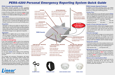
PERS ConsoleWristband Sensor Smoke SensorPendant Sensor Carbon Monoxide Sensor HOME BUTTON / INDICATOR• Press for 5 seconds to switch between • Blinks green when the activity timer is running • Flashes green when less than 15 minutes MICROPHONE• Used for 2-way communications • Used during Speakerphone Mode• Speaks voice announcements • Speaks reminder messages • Used for 2-way voice communications • Used during Speakerphone ModeOPTION MODULE(S)• One or two option modules can be installed • Modules plug into the rear of the Console • Option for cellular telephone reporting• Option for a wireless remote speaker / microphoneHELP BUTTON / INDICATOR• Press to trigger the emergency alarm • Press to answer an incoming call if Speakerphone Mode is enabled • Lights green during normal operation • Flashes red while sending alarm reports to the monitoring service • Lights orange during Speakerphone Mode • Flashes green every 3 seconds when the Console is without AC power and running on the backup battery • Blinks green when the Console battery is chargingCANCEL BUTTON / INDICATOR• Silences a pending alarm or reminder message • Press to clear alarm and silence announcements• Press for 3 seconds for sensor Learn Mode • Press to exit Test Mode or Learn Mode • Lights yellow for sensor fault • Blinks yellow for sensor low batteryesting Sensors Sensor Fault ConditionsService Information System ConnectionsIt's important to test your system at least once a monthor when the automatic test reminder message plays.CAUTION: BEFORE TESTING YOURSELF, CALL THE MONITORING SERVICE TO NOTIFY THEM THAT YOU WILL BE TESTING Testing should be done from all portable sensors and the Console.er.earned".resume(Status announcements will not sound while the Console is in Night Mode.)NOTE: Status reports arenot monitored while theConsole is in Away ModeFor service, refer to the information below.(Your monitoring service will typically make these connections.)The Console connects to power and the telephone.PERSCo ns oleHELPWARNING: THE CONSOLE WILL NOT BE ABLE TO REPORTAN EMERGENCY WHILE THE SPEAKERPHONE IS ACTIVEk erp ho ne. Th e HELP bu tto n w i ll lNOTE: TO REPORT AN EMERGENCY WHEN THE SPEAKERPHONE IS IN USE, PRESS EITHER THEBUTTON OR A PENDANT BUTTON TO END THE PHONE CALL AND THEN PRESS ONE OFTHESE BUTTONS AGAIN TO REPORT THE EMERGENCY.WARNING: THE CONSOLE WILL NOT BE ABLE TO REPORTAN EMERGENCY WHILE THE SPEAKERPHONE IS ACTIVENOTE: TO REPORT AN EMERGENCY WHEN THE SPEAKERPHONE IS IN USE, PRESS EITHER THEBUTTON OR A PENDANT BUTTON TO END THE PHONE CALL AND THEN PRESS ONE OFerspea k er.Cancel button"Cancel button"______________________n the da te.。
IDEAL-100型紫别传感器利用说明书中外合伙淄博爱迪尔测控技术尊重的用户:十分感激您利用我公司生产的产品。
利用本产品前请认真阅读这些说明。
本说明书中描述的产品只能适合通过培训合格的工作者利用。
本产品的调整、修理和保护必需由厂商指定的授权人员进行。
为正确及平安利用本产品,需要依照本说明书进行操作。
厂商建议维持产品标签完整。
厂商建议不要拆开本产品。
厂商建议本产品的所有保护和校准操作需要依照利用说明书中的要求进行。
厂商不对由于利用产品不妥造成的损害或损害承担任何责任。
厂商改良产品规格或修改说明书中的内容,恕不另行通知。
若是需要最新的产品规格或利用说明书,请及时与经销商或厂家联系。
咱们会尽可能完善本说明书以保证其内容的准确性。
若是您在本说明书中发觉任何错误,请同咱们联系,咱们表示超级感激。
未经我公司许诺,严禁拷贝和仿造本说明书全数或部份内容,违者必究。
本利用说明书包括紫别传感器的结构说明、功能介绍、接线方式和操作说明和注意事项。
为了保证正确利用本仪器,请您在利用以前详细阅读本说明书,并把其保留在平安方便的地址以便于显现问题时迅速查找。
目录一、二、三、四、五、一、产品概述小型紫别传感器要紧用于臭氧发生器出口臭氧浓度检测,采纳紫外灯管为光源系统,利用寿命是3万个小时以上,测量数据稳固、精度高;采纳仿造广州立美光池结构,具有无泄漏、耐压高、耐大流量采样气体冲击、易清洁、保护方便、操作简单。
在利用进程中设备手动校零,保证了浓度的准确性而且幸免了零漂,具有4-20mA及RS-485信号输出。
小型紫别传感器是光电转换检测技术具体应用的高新技术产物。
采纳了先进的微处置器操纵技术,长寿命脉冲方式光源,利用臭氧对紫外光特点吸收的特性,依据比尔—郎伯(Beer-Lambert )定律设计的紫别传感器。
具有设计寿命长;数据稳固精度高;利用、保护方便、操作简单等特点。
臭氧是一种强氧化剂,具有很强的杀菌消毒、漂白、除味等特性,普遍应用于水消毒、食物加工杀菌净化、食物贮藏保鲜、医疗卫生和家庭消毒净化等方面的产品。
紫外检测仪使用说明一、紫外检测仪概述:紫外检测仪是液相色谱中的一种紫外装置,仪器配上层析柱,恒流泵,部分收集器等,即组成一完整的液相色谱分离分析装置,它是从现代生物学研究,药物测定、农业科研、化工、食品及医疗单位对具有紫外吸收的样品的作定量分析,本仪器主要元件器采用进口,光电培增管IP28型,性能稳定、灵敏度高等。
二、紫外检测仪主要技术指标:1、核酸蛋白检测仪波长:254nm、280nm2、紫外检测仪波长:220nm、254nm、280nm、340nm3、样品池,容积100微升,光程3毫米4、量程范围:0-100%T、0-2A、0-1A、0-0.5A、0-0.2A、0-0.1A、0-0.05A5、LED数字显示6、仪器可连续工作一周7、电源:220VAC±10%50HZ8、温度:-5℃~35℃三、紫外检测仪工作原理:仪器工作原理的依据是光吸收定律。
从光源发出的光经狭缝、滤光片、样品池到光电培增管上,使束由于样品浓度不同所引起光强的变化转换成光电流的变化,此光电流经放大器输入到对数转换器,使透光率T转成A输出,即A=1g — =εCL式中ε为待测样品的克分子消光系统,C为样品浓度,采用克分子/升单位,L为光程,用厘米作单位。
根据上式就知测出了A,就知样品浓度C。
若从放大器直接输入记录仪,绘出的是样品透光率T变化的图谱,若从对数转换器输入到记录仪绘出的是样品光密度A变化的图谱。
四、紫外检测仪仪器结构:它由一组光源,四块干涉滤色片,一块聚光透镜,一只样品池,一只光电倍增管,一块放大板和一块对数板等组成,面板上有聚乙稀塑料管的进样口和出样口,A调零以及调节“光量”大小旋钮(光量大小以箭头表示)。
还有光源指示灯、电源指示灯以及量程转换旋钮。
光源主要提供220、254、280、340毫微米分别作为检测核酸、蛋白、酶、多肽的光源。
滤色器由220、254、280、340毫微米谱线外尚含有其它波长的谱线,通过各自所对应的滤色片就把非谱线波长以外的其它波长滤去,这保证了仪器的单色性。

OS100 SERIES Mini-Infrared Transmitter e-mail:**************For latest product manuals: Shop online at User’s G ui d e***********************Servicing North America:U.S.A. Omega Engineering, Inc.Headquarters: Toll-Free: 1-800-826-6342 (USA & Canada only)Customer Service: 1-800-622-2378 (USA & Canada only)Engineering Service: 1-800-872-9436 (USA & Canada only)Tel: (203) 359-1660 Fax: (203) 359-7700e-mail:**************For Other Locations Visit /worldwideThe information contained in this document is believed to be correct, but OMEGA accepts no liability for any errors it contains, and reserves the right to alter specifications without notice.Table of ContentsSection ...................................................................PageSafety Warnings and IEC Symbols (iii)Caution and Safety Information (iii)Section 1 Introduction ....................................................................1-1Section 2Installation ......................................................................1-12.1 Unpacking and Inspection ......................................1-12.2 Electrical Connection ..............................................2-1Section 3Operation ........................................................................3-13.1 Main Board ................................................................3-13.2 Ambient Temperature ..............................................3-23.3 Atmospheric Quality ................................................3-33.4 Measuring Temperature ..........................................3-33.5 Alarm Setting ............................................................3-43.6 Adding Extension Cable...........................................3-4Section 4 Laser Sight Accessory ...................................................4-14.1 Warning and Cautions .............................................4-14.2 Operating the Laser Sight Accessory .....................4-1Section 5 Specifications .................................................................5-15.1 General .......................................................................5-15.2 Laser Sight Accessory (OS100-LS) ..........................5-2Section 6Emissivity Table .............................................................6-1iTable of FiguresFigure Description Page2-1Power Supply & Analog Output Connections ..........2-12-2 Alarm Output Connection ............................................2-13-1 Main PC Board ...............................................................3-23-2 Sensor..............................................................3-2Housing3-3 Optical Field of View .....................................................3-43-4Setting the Temperature Engineering Unit..................3-43-5Mounting Bracket OS100-MB .......................................3-53-6Water Cooling Jacket, OS100-WC ................................3-53-7Typical Water Cool Jacket Assembly ...........................3-53-8Air Purge Collar, OS100-AP..........................................3-63-9DIN Rail Mounting Adapter, OS100-DR ....................3-63-10NEMA-4 Aluminum Enclosure ....................................3-64-1Laser Sighting Accessory, OS100-LS ............................4-24-2Laser Warning Label ......................................................4-2iiSafety Warnings and IEC SymbolsThis device is marked with international safety and hazard symbols in accordance with IEC 1010. It is important to read and follow all precautions and instructions in this manual before operating or commissioning this device as it contains important information relating to safety and EMC. Failure to follow all safety precautions may result in injury and or damage to your calibrator. IEC symbols DescriptionCaution and Safety Information• If the equipment is used in a manner not specified in this manual, the protection provided by the equipment may be impaired.• The installation category is one (1).• There are no user replaceable fuses in this product• The output terminals of this product are for use with equipment (digital meters, chart recorders, etc,) which have no accessible five parts. Such equipment should comply with all the applicable safety requirements.• Do not operate the equipment in flammable or explosive environments.• All connections to the thermometer should be made via a shielded cable, 24 AWG stranded wire with the following ratings: 300V , 105°C (221°F), PVC insulation.• Power must be disconnected before making any electrical connections.• The power supply used to power the thermometer should be VDE or UL approved with the following ratings: 12 to 24vdc @150mA with overload protection of 500mA.iiiCaution, refer to accompanying documentsDirect Current Laser SymbolFrame or ChassisNOTES: ivSection 1 - IntroductionThe low cost OS101 mini-infrared transmitter provides non-contacttemperature measurement for industrial applications. The unit measures atemperature range of -18 to 538°C (0-1000°F) and provides a linear analogoutput of either 4-20 mA, 0-5 VDC, K type TC, 1 mV/°C, or 1 mV/°F.The new OS102 mini-infrared transmitter has all the functions of OS101plus a built-in LED display that shows the measured temperature indegrees F or degrees C which is switchable in the field.The miniature sensor head design 2.5 cm dia. x 6.3 cm Length (1" x 2.5") isideal for measuring temperature in confined, and hard to reach places.The aluminum sensor head as well as the rugged electronic housing (Diecast Aluminum) are NEMA-4 rated.The sensor head is connected to the electronic housing via a 1.82 m (6 feet)shielded cable as standard. The unit provides field adjustable alarmoutput.Section 2 - Installation2.1UnpackingRemove the packing list and verify that you have received all yourequipment. If you have any questions about the shipment, please callCustomer Service at:1-800-622-2378 or 203-359-1660. We can also be reached on the internet:e-mail:**************When you receive the shipment, inspect the container and equipment forany signs of damage. Note any evidence of rough handling in transit.inspection. After examination and removing contents, save packing material and carton in theevent reshipment is necessary.The following items are supplied in the box:• The infrared transmitter including the sensor head and the 1.82 m(6 feet) shielded cable• User's Manual• Mounting Nut1-1The following describes the ordering information:OS102 or OS101 - MA- *,**, where The following optional accessories are available:Here are the Features of OS101 and OS102 infrared transmitters:2.2Electrical Connection Sensor Head Cable - The Sensor head is pre-wired to a 1.8 m (6 feet)shielded cable. Plug & lock-in the male connector to the mating female connector on the aluminum housing.Power & Output Connection - Open the cover of the main aluminum housing. Slide the cable through the strain relief and connect the wires to the terminal block on the board as shown in Fig. 2-1. For Alarm output connection, refer to Fig. 2-2.2-1MA - 4/20 mA output V1 - 0 to 5 VDC output K - Thermocouple output, K type MV - Millivolt output C - 1 mV/°C output F - 1 mV/°F output HT- High temperature sensor head3-1Figure 2-2. Alarm Output Connection Section 3 - Operation3-1Main BoardThe Main Board is shown in Fig. 3-1. Here are the important components on the board:(1) - Terminal Block for Power & Output connections(2) - Single Turn Potentiometer to adjust Emissivity in tenths (0.x_)(3) - Single Turn Potentiometer to adjust Emissivity in hundreds (0._x)(4) -Slide switch to select between real time (Normal Operation) and alarm set point(5) - Alarm set point adjust, P4(6) - Sensor Head connection(7) - Input Zero adjust, P3(8) - Input Span adjust, P2(9) - Output Zero adjust, P5(10) - Output Span adjust, P6Figure 3-1. Main PC Board3.2Ambient TemperatureThe Sensing head can operate in an ambient temperature of 0 to 70°C (32to 158°F). The Sensing head in the high temperature model (-HT) can operate in an ambient temperature of 0 to 85°C (32 to 185°F) without any cooling required. The Sensing head can operate up to 200°C (392°F) using the water cool jacket accessory OS100-WC (See Fig. 3-6).There is a warm up period of 3 minutes after power up. After the warm up period, temperature measurement can be made.When the ambient temperature around the sensor head changes abruptly,the sensor head goes through thermal shock. It takes a certain amount of time for the sensor head to stabilize to the new ambient temperature. For example, it takes about 30 minutes for the sensor head to stabilize going from 25°C to 50°C (77 to 122°F) ambient temperature.The sensor head dimensions are shown in Fig. 3-2.Figure 3-2. Sensor Housing3-23-33.3Atmospheric QualityEnvironments with smoke, dust, and fumes dirty up the optical lens, and cause erroneous temperature readings. To keep the surface of the optical lens clean, the air purge collar accessory is recommended, OS100-AP , See Fig. 3-7.3.4Measuring TemperatureBefore starting to measure temperature, make sure that the following check list is met:ߜ The power and analog output connections are made (Fig. 2-1).ߜThe sensor head is connected to the main unit.ߜThe slide switch (SW1) on the main board is set to real time (Fig. 3-1).ߜThe target is larger than the optical field of view of the sensor head (Fig. 3-3).ߜThe emissivity adjustment on the main board is set properly (Fig. 3-1).ߜThe output load is within the product specification.On OS102 transmitters, follow these additional steps:ߜ The temperature display is set to °F or °C (Fig. 3-4)ߜ For 4-20mA output models, make sure an output load is added, ie. 250ohms.Figure 3-3. Optical Field Of ViewFigure 3-4. Setting the Temperature Engineering Unit3.5Alarm SettingThe unit provides 0-100% alarm set point adjustment. Here is an exampleof an alarm setting.• An OS101-MA(4/20 mA output), the alarm is to be set at 400°Ftemperature.• Connect the alarm output as shown in Fig. 2-2.• Set the slide switch (SW1) on the main board to the Alarm position.• Measure the analog output, and set the Potentiometer P4 until theoutput reads 10.4 mA which is 40% (400°F) of the temperature range.40 x (20-4)[10.4mA=+ 4]100• Set the slide switch (SW1) back to the Real Time position.• If the temperature reading is below the alarm set point, the alarmoutput stays high, otherwise it goes low.On the OS102, you can set the alarm set point directly based on thetemperature display.3.6Adding Extension CableYou can add extension cable between the Sensor Head and the mainelectronic housing up to 15.2 m (50 feet). After adding the extension cable,the Zero input potentiometer, P3 may be re-adjusted. (See Fig. 3-1, forproper analog output reading)The following figures show the mounting bracket (OS100-MB), Watercooling jacket (OS100-WC), Air purge collar (OS100-AP), DIN RailMounting adapter (OS-100-DR), and the main aluminum enclosure. TheDIN Rail Mounting adapter (OS100-DR) is mounted to the bottom of themain aluminum enclosure using two 4-40 screws.A typical water cool jacket assembly is shown in Fig. 3-7, on the following page.1. Mounting Nut2. Mounting Bracket3. Water Cool Jacket4. Sensor Head3-4Figure 3-5. Mounting Bracket OS100-MBFigure 3-6. Water Cooling Jacket, OS100-WCFigure 3-7. Typical Water Cool Jacket Assembly3-5Figure 3-8. Air Purge Collar, OS100-APFigure 3-9. DIN Rail Mounting Adapter, OS-100-DRFigure 3-10. NEMA-4 Aluminum Enclosure3-6Section 4 - Laser Sight Accessory4.1Warning and Cautionsbelow:•Use of controls or adjustments or performance of procedures other than those specified here may result in hazardous radiation exposure.• Do not look at the laser beam coming out of the lens or view directly with optical instruments - eye damage can result.• Use extreme caution when operation the laser sight accessory • Never point the laser accessory at a person • Keep out of the reach of all children4.2Operating the Laser Sight AccessoryThe laser sight accessory screws onto the front of the sensor head. This accessory is only used for alignment of the sensor head to the target area.After the alignment process, the accessory has to be removed from the front of the sensor head before temperature measurement.The laser sight accessory is powered from a small compact battery pack (included with the accessory). Connect the battery pack to the accessory using the cable provided. Aim at the target, and turn on the battery power using the slide switch on the battery pack. Adjust the sensor head position so that the laser beam points to the center of the target area. Turn off the battery pack, and remove the laser sighting accessory from the sensor head. See Fig. 4-1 for reference.4-14-2Figure 4-2. Laser Warning LabelSection 5 - Specifications5.1 - GeneralTemperature Range-18 to 538°C (0 to 1000°F)Accuracy @ 22°C (72°F)±2% of Rdg. or 2.2°C (4°F) whichever is ambient temperature & greateremissivity of 0.95 or greaterOptical Field of View6:1 (Distance/Spot Size)Repeatability±1% of Rdg.Spectral Response 5 to 14 micronsResponse Time150 msec (0 to 63% of final value)Emissivity Range0.1 to 0.99, adjustableOperating Ambient TemperatureMain Transmitter0 to 50°C (32 to 122°F)Sensor Head0 to 70°C (32 to 158°F)Sensor Head (-HT Model)0 to 85°C (32 to 185°F)Sensor Head with OS100-WC(Water Cooling Jacket)0 to 200°C (32 to 392°F)Operating Relative Humidity Less than 95% RH, non-condensingWater Flow Rate for OS100-WC0.25 GPM, room temperatureThermal Shock About 30 minutes for 25°Cabrupt ambient temperature change Warm Up Period 3 minutesAir Flow Rate for OS100-AP 1 CFM (0.5 Liters/sec.)Power12 to 24 VDC @ 100 mAAnalog OutputsMV-F 1 mV/°FMV-C 1 mV/°CK K Type TC - OS101 onlyMA 4 to 20 mAV10 to 5 VDCOutput Load requirementsMin. Load (0 to 5VDC) 1 K-OhmsMax. Load (4 to 20 mA)(Supply Power - 4 )/20 mATransmitter Housing NEMA-4 & IP65, Die Cast AluminumSensor Head Housing NEMA-4 , AluminumAlarm Output Open Drain, 100 mAAlarm Set Point0 to 100% , Adjustable via P4Alarm Deadband14°C (25°F)5-15-25.1 - General Con’t.DimensionsSensor Head25.4 OD. x 63.5 mm L(1" OD. x 2.5" L)Main Housing, OS10165.5 W x 30.5 H x 115.3 mm L(2.58" W x 1.2" H x 4.54" L)Main Housing, OS10265.5 W x 55.9 H x 115.3 mm L(2.58" W x 2.2" H x 4.54" L)Weight 272 g (0.6 lb)5.2Laser Sight Accessory (OS100-LS)Wavelength (Color)630 - 670 nm (Red)Operating Distance (Laser Dot)Up to 9.1 m (30 ft.)Max. Output Optical Power Less than 1 mW at 22°F ambienttemperature.European Classification Class 2, EN60825-1/11.2001Maximum Operating current45 mA at 3 VDCFDA Classification Complies with 21 CFR 1040.10,Class II Laser ProductBeam Diameter 5 mmBeam Divergence< 2 mradOperating Temperature0 to 50°C (32 to 122°F)Operating Relative Humidity Less than 95% RH, non-condensingPower Switch ON / OFF , Slide switch on the BatteryPackPower Indicator Red LEDPower Battery Pack, 3 VDC (Consists of two 1.5VDC AA size Lithium Batteries) Laser Warning Label Located on the head sight circumferenceIdentification Label Located on the head sight circumferenceDimensions38 DIA x 50.8 mm L(1.5" DIA x 2" L)Section 6 - Emissivity Table6-1Material Emissivity (ε)Aluminum – pure highly polished plate . . . . . . . . . . . . . . . . . . . . . . . . 0.04 to 0.06Aluminum – heavily oxidized . . . . . . . . . . . . . . . . . . . . . . . . . . . . . . . 0.20 to 0.31Aluminum – commercial sheet . . . . . . . . . . . . . . . . . . . . . . . . . . . . . . . . . . . . 0.09Brass – dull plate. . . . . . . . . . . . . . . . . . . . . . . . . . . . . . . . . . . . . . . . . . . . . . 0.22Brass – highly polished, 73.2% Cu, 26.7% Zn. . . . . . . . . . . . . . . . . . . . . . . . . 0.03Chromium – polished. . . . . . . . . . . . . . . . . . . . . . . . . . . . . . . . . . . . . 0.08 to 0.36Copper – polished. . . . . . . . . . . . . . . . . . . . . . . . . . . . . . . . . . . . . . . . . . . . . 0.05Copper – heated at 600°C (1112°F). . . . . . . . . . . . . . . . . . . . . . . . . . . . . . . 0.57Gold – pure, highly polished or liquid. . . . . . . . . . . . . . . . . . . . . . . . . 0.02 to 0.04Iron and steel (excluding stainless)– polished iron . . . . . . . . . . . . . . . . 0.14 to 0.38Iron and steel (excluding stainless)– polished cast iron. . . . . . . . . . . . . . . . . . . 0.21Iron and steel (excluding stainless)– polished wrought iron . . . . . . . . . . . . . . . 0.28Iron and steel (excluding stainless)– oxidized dull wrought iron . . . . . . . . . . . . 0.94Iron and steel (excluding stainless)– rusted iron plate . . . . . . . . . . . . . . . . . . . 0.69Iron and steel (excluding stainless)– polished steel. . . . . . . . . . . . . . . . . . . . . . 0.07Iron and steel (excluding stainless)– polished steel oxidized at600°C (1112°F). . . . . . . . . . . . . . . . . . . . 0.79Iron and steel (excluding stainless)– rolled sheet steel . . . . . . . . . . . . . . . . . . . 0.66Iron and steel (excluding stainless)– rough steel plate . . . . . . . . . . . . . 0.94 to 0.97Lead – gray and oxidized . . . . . . . . . . . . . . . . . . . . . . . . . . . . . . . . . . . . . . . 0.28Mercury . . . . . . . . . . . . . . . . . . . . . . . . . . . . . . . . . . . . . . . . . . . . . 0.09 to 0.12Molybdenum filament . . . . . . . . . . . . . . . . . . . . . . . . . . . . . . . . . . . . 0.10 to 0.20Nickel – polished . . . . . . . . . . . . . . . . . . . . . . . . . . . . . . . . . . . . . . . . . . . . . 0.07Nickel – oxidized at 649 to 1254°C (1200°F to 2290°F). . . . . . . . . . . 0.59 to 0.86Platinum – pure polished plate . . . . . . . . . . . . . . . . . . . . . . . . . . . . . . 0.05 to 0.10Platinum – wire . . . . . . . . . . . . . . . . . . . . . . . . . . . . . . . . . . . . . . . . 0.07 to 0.18Silver – pure and polished . . . . . . . . . . . . . . . . . . . . . . . . . . . . . . . . . 0.02 to 0.03Stainless steel – polished . . . . . . . . . . . . . . . . . . . . . . . . . . . . . . . . . . . . . . . . 0.07Stainless steel – Type 301 at 232 to 942°C (450°F to 1725°F). . . . . . . 0.54 to 0.63Tin – bright . . . . . . . . . . . . . . . . . . . . . . . . . . . . . . . . . . . . . . . . . . . . . . . . . 0.06Tungsten – filament . . . . . . . . . . . . . . . . . . . . . . . . . . . . . . . . . . . . . . . . . . . . 0.39Zinc – polished commercial pure . . . . . . . . . . . . . . . . . . . . . . . . . . . . . . . . . . 0.05Zinc – galvanized sheet. . . . . . . . . . . . . . . . . . . . . . . . . . . . . . . . . . . . . . . . . 0.23M E T A L S6-2Material Emissivity (ε) Asbestos Board . . . . . . . . . . . . . . . . . . . . . . . . . . . . . . . . . . . . . . . . . . . . . . .0.96 Asphalt, tar, pitch . . . . . . . . . . . . . . . . . . . . . . . . . . . . . . . . . . . . . . .0.95 to 1.00 Brick– red and rough . . . . . . . . . . . . . . . . . . . . . . . . . . . . . . . . . . . . . . . . . .0.93 Brick– fireclay . . . . . . . . . . . . . . . . . . . . . . . . . . . . . . . . . . . . . . . . . . . . . . .0.75 Carbon– filament . . . . . . . . . . . . . . . . . . . . . . . . . . . . . . . . . . . . . . . . . . . . .0.53 Carbon– lampblack - rough deposit . . . . . . . . . . . . . . . . . . . . . . . . . .0.78 to 0.84 Glass- Pyrex, lead, soda . . . . . . . . . . . . . . . . . . . . . . . . . . . . . . . . . .0.85 to 0.95 Marble– polished light gray . . . . . . . . . . . . . . . . . . . . . . . . . . . . . . . . . . . . .0.93 Paints, lacquers, and varnishes– Black matte shellac . . . . . . . . . . . . . . . . . . . .0.91 Paints, lacquers, and varnishes– aluminum paints . . . . . . . . . . . . . . . .0.27 to 0.67 Paints, lacquers, and varnishes– flat black lacquer . . . . . . . . . . . . . . .0.96 to 0.98 Paints, lacquers, and varnishes– white enamel varnish . . . . . . . . . . . . . . . . . .0.91 Porcelain– glazed . . . . . . . . . . . . . . . . . . . . . . . . . . . . . . . . . . . . . . . . . . . . .0.92 Quartz– opaque . . . . . . . . . . . . . . . . . . . . . . . . . . . . . . . . . . . . . . . .0.68 to 0.92 Roofing Paper . . . . . . . . . . . . . . . . . . . . . . . . . . . . . . . . . . . . . . . . . . . . . . .0.91 Tape– Masking . . . . . . . . . . . . . . . . . . . . . . . . . . . . . . . . . . . . . . . . . . . . . .0.95 Water . . . . . . . . . . . . . . . . . . . . . . . . . . . . . . . . . . . . . . . . . . . . . . . .0.95 to 0.96 Wood– planed oak . . . . . . . . . . . . . . . . . . . . . . . . . . . . . . . . . . . . . . . . . . . .0.90 NONMETALSNOTES:6-3NOTES: 6-4OMEGA’s policy is to make running changes, not model changes, whenever an improvement is possible. T his affords our customers the latest in technology and engineering.OMEGA is a trademark of OMEGA ENGINEERING, INC.© Copyright 2017 OMEGA ENGINEERING, INC. All rights reserved. T his document may not be copied, photocopied, reproduced, translated, or reduced to any electronic medium or machine-readable form, in whole or in part, without the prior written consent of OMEGA ENGINEERING, INC.FOR WARRANTY RETURNS, please have the following information available BEFORE contacting OMEGA:1. P urchase Order number under which the product was PURCHASED,2. M odel and serial number of the product under warranty, and3. Repair instructions and/or specific problems relative to the product.FOR NON-WARRANTY REPAIRS, consult OMEGA for current repair charges. Have the following information available BEFORE contacting OMEGA:1. Purchase Order number to cover the COST of the repair,2. Model and serial number of the product, and 3. Repair instructions and/or specific problems relative to the product.RETURN REQUESTS/INQUIRIESDirect all warranty and repair requests/inquiries to the OMEGA Customer Service Department. BEFORE RET URNING ANY PRODUCT (S) T O OMEGA, PURCHASER MUST OBT AIN AN AUT HORIZED RET URN (AR) NUMBER FROM OMEGA’S CUST OMER SERVICE DEPART MENT (IN ORDER T O AVOID PROCESSING DELAYS). The assigned AR number should then be marked on the outside of the return package and on any correspondence.T he purchaser is responsible for shipping charges, freight, insurance and proper packaging to preventbreakage in transit.WARRANTY/DISCLAIMEROMEGA ENGINEERING, INC. warrants this unit to be free of defects in materials and workmanship for a period of 25 months from date of purchase. OMEGA’s WARRANTY adds an additional one (1) month grace period to the normal two (2) year product warranty to cover handling and shipping time. This ensures that OMEGA’s customers receive maximum coverage on each product.If the unit malfunctions, it must be returned to the factory for evaluation. OMEGA’s Customer Service Department will issue an Authorized Return (AR) number immediately upon phone or written request. Upon examination by OMEGA, if the unit is found to be defective, it will be repaired or replaced at no charge. OMEGA’s WARRANT Y does not apply to defects resulting from any action of the purchaser, including but not limited to mishandling, improper interfacing, operation outside of design limits, improper repair, or unauthorized modification. T his WARRANT Y is VOID if the unit shows evidence of having been tampered with or shows evidence of having been damaged as a result of excessive corrosion; or current, heat, moisture or vibration; improper specification; misapplication; misuse or other operating conditions outside of OMEGA’s control. Components in which wear is not warranted, include but are not limited to contact points, fuses, and triacs.OMEGA is pleased to offer suggestions on the use of its various products. However, OMEGA neither assumes responsibility for any omissions or errors nor assumes liability for any damages that result from the use of its products in accordance with information provided by OMEGA, either verbal or written. OMEGA warrants only that the parts manufactured by the company will be as specified and free of defects. OMEGA MAKES NO OTHER WARRANTIES OR REPRESENTATIONS OF ANY KIND WHATSOEVER, EXPRESSED OR IMPLIED, EXCEPT THAT OF TITLE, AND ALL IMPLIED W ARRANTIES INCLUDING ANY W ARRANTY OF MERCHANTABILITY AND FITNESS FOR A PARTICULAR PURPOSE ARE HEREBY DISCLAIMED. LIMITATION OF LIABILITY: The remedies of purchaser set forth herein are exclusive, and the total liability of OMEGA with respect to this order, whether based on contract, warranty, negligence, indemnification, strict liability or otherwise, shall not exceed the purchase price of the component upon which liability is based. In no event shall OMEGA be liable for consequential, incidental or special damages.CONDITIONS: Equipment sold by OMEGA is not intended to be used, nor shall it be used: (1) as a “Basic Component” under 10 CFR 21 (NRC), used in or with any nuclear installation or activity; or (2) in medical applications or used on humans. Should any Product(s) be used in or with any nuclear installation or activity, medical application, used on humans, or misused in any way, OMEGA assumes no responsibility as set forth in our basic WARRANT Y /DISCLAIMER language, and, additionally, purchaser will indemnify OMEGA and hold OMEGA harmless from any liability or damage whatsoever arising out of the use of theProduct(s) in such a manner.Where Do I Find Everything I Need forProcess Measurement and Control?OMEGA…Of Course!Shop online at TEMPERATUREM U Thermocouple, RTD & Thermistor Probes, Connectors,Panels & AssembliesM U Wire: Thermocouple, RTD & ThermistorM U Calibrators & Ice Point ReferencesM U Recorders, Controllers & Process MonitorsM U Infrared PyrometersPRESSURE, STRAIN AND FORCEM U Transducers & Strain GagesM U Load Cells & Pressure GagesM U Displacement TransducersM U Instrumentation & AccessoriesFLOW/LEVELM U Rotameters, Gas Mass Flowmeters & Flow ComputersM U Air Velocity IndicatorsM U Turbine/Paddlewheel SystemsM U Totalizers & Batch ControllerspH/CONDUCTIVITYM U pH Electrodes, Testers & AccessoriesM U Benchtop/Laboratory MetersM U Controllers, Calibrators, Simulators & PumpsM U Industrial pH & Conductivity EquipmentDATA ACQUISITIONM U Communications-Based Acquisition SystemsM U Data Logging SystemsM U Wireless Sensors, Transmitters, & ReceiversM U Signal ConditionersM U Data Acquisition SoftwareHEATERSM U Heating CableM U Cartridge & Strip HeatersM U Immersion & Band HeatersM U Flexible HeatersM U Laboratory HeatersENVIRONMENTALMONITORING AND CONTROLM U Metering & Control InstrumentationM U RefractometersM U Pumps & TubingM U Air, Soil & Water MonitorsM U Industrial Water & Wastewater TreatmentM U pH, Conductivity & Dissolved Oxygen InstrumentsM3572/1217。

Photoelectric Sensors2.144BMOA Miniature Remote Amplifier SensorsNeed the precision of a laserphotoelectric sensor, but have no room to mount something that big? Ultra miniaturesensing heads down to 2 mmcan fit into applications wheremost sensors won’t. The BMOA component systems use an amplifier to power and control the signals from the sensing head, making it a unique alternative to typical fiber optic solutions. The BMOA component systems offer maximum flexibility with high flex cable versions for moving applications likerobotic arms. The systems can detect targets as small as 0.05 mm. The BMOAamplifiers make set-up and operation easy, using a simpledynamic teach function, or amanual push-button adjustment mode. Available in economical discrete or advanced analog outputversions to solve difficult applications.Features– Smallest sensing head in the industry– Laser-like precision to detect targets as small as 0.05 mm – High speed switching up to 5 kHz– 50 ms pulse stretching delay – Simple pushbuttonadjustment of dynamic teach function– Stability and Output Function LEDs– Discrete output versions PNP and NPN– Analog Output versions 0…10 Vdc and 4…20 mA – Din-rail or panel mountable Applications– Thread detection – Small part profiling – Robotic end-effectors– Semiconductor component detection– High performance alternative to fiber opticsBMOAMiniature Remote Amplifier SensorsBMO A01... amplifiers only.C o u r t e s y o f C M A /F l o d y n e /H y d r a d y n e ▪ M o t i o n C o n t r o l ▪ H y d r a u l i c ▪ P n e u m a t i c ▪ E l e c t r i c a l ▪ M e c h a n i c a l ▪ (800) 426-5480 ▪ w w w .c m a f h .c o m2.145t p76o amplifier connectoramplifier connectoramplifier connectorC o u r t e s y o f C M A /F l o d y n e /H y d r a d y n e ▪ M o t i o n C o n t r o l ▪ H y d r a u l i c ▪ P n e u m a t i c ▪ E l e c t r i c a l ▪ M e c h a n i c a l ▪ (800) 426-5480 ▪ w w w .c m a f h .c o mPhotoelectric Sensors2.146High SpeedBMO A01-I-PU-C-02BMO A01-I-NU-C-02SeriesDiscrete Output PNP Normally-open NPNNormally-open Analog Output 0...10 Vdc 4...20 mASupply VoltageVoltage Drop U d at I e Output Current (digital)Analog Output Type (Voltage)Analog Output Type (Current)Analog Output Load (voltage) min load Analog Output Load (current) Max Load Current Consumption I o (no load)Protections Response TimeSwitching FrequencyPulsed/Non-Pulsed Light Source Output FunctionOperating Temperature Range Degree of Protection per IEC 60529Sensitivity/Range Adjustment Power/Stability Indication Alarm Indication Output LEDHousing MaterialWeightConnection (to control system)10…30 Vdc< 2 V 100 mA 45 mAShort Circuit, Reverse Polarity100 µs 5 KHz Non-PulsedLight/Dark Selectable -10° C to +55° CIP 65Teach-in and ManualGreen LED Yellow LED ABS 55 g2 m PVC Cable ,3 x 26 AWGq w e rBMOAMiniature Remote Amplifier SensorsSensitivity settingAUT – the amplifier will determine the best setting for the application.MAN – this allows you to fine-tune the settings or manually adjust the sensor for difficult applications.Wiring DiagramsOutput GNDOutput GNDrC o u r t e s y o f C M A /F l o d y n e /H y d r a d y n e ▪ M o t i o n C o n t r o l ▪ H y d r a u l i c ▪ P n e u m a t i c ▪ E l e c t r i c a l ▪ M e c h a n i c a l ▪ (800) 426-5480 ▪ w w w .c m a f h .c o mFiber Optics/photoelectricObject Resolution for Diffuse Sensors42-2-4-6-8Y(mm)055M, 06TM & 66RMYMeasuring Arrangement:900a standard resolution amplifier.04SM, 05TM & 66RMthe beam at certain ranges.Sensing Distance for Diffuse Sensors0.8% 1.6% 3.1% 6.3% 12.5% 25% 50% 100%Absolute Mode (ABS)This mode offers the maximum accuracy for allapplications. The amplifier will offer 8 stages ofCourtesyofCMA/Flodyne/Hydradyne▪MotionControl▪Hydraulic▪Pneumatic▪Electrical▪Mechanical▪(8)426-548▪www.cmafh.co m。

紫外检测仪说明书1、原理紫外吸收检测器简称紫外检测器(ultraviolet detector,UVD),是基于溶质分子吸收紫外光的原理设计的检测器,其工作原理是Lambert-Beer定律,即当一束单色光透过流动池时,若流动相不吸收光,则吸收度A与吸光组分的浓度C和流动池的光径长度L成正比。
物理上测得物质的透光率,然后取负对数得到吸收度。
大部分常见有机物质和部分无机物质都具有紫外或可见光吸收基团,因而有较强的紫外或可见光吸收能力,因此UVD既有较高的灵敏度,也有很广泛的应用范围,是液相色谱中应用最广泛的检测器。
紫外检测器的波长范围是根据连续光源(氘灯)发出的光,通过狭缝、透镜、光栅、反射镜等光路组件形成单一波长的平行光束。
通过光栅的调节可得到不同波长。
波长范围应该是根据光源来确定的,不同光源波长范围也不一样。
光波根据光的传播频率不一样而划分的。
紫外的测量范围一般为0.0003---5.12(AUFS),常用为0.005---2.0(AUFS)。
紫外光的范围一般指200-400 nm。
吸收度单位AU (absorbance unit) 是相当于多少伏的电压,范围的大小应该适中较好,实际工作中一般就需要1AU 左右。
核酸蛋白检测仪*工作原理所有紫外吸收检测器工作原理都是基于光的吸收定律---朗伯-比耳定律。
光源经220nm、254nm、280nm、340nm等干涉滤色片提供单色光作为检测核酸、蛋白、酶、多肽的光源。
具体工作原理正如该定律指出,当一束单色光(λ)辐射通过稀浓度物质溶液时,如果溶剂不吸收光,则液体的吸光度与吸光物质的浓度和光经过溶液的距离成正比。
其关系式为:A(λ)=a(λ)bcA=-LgT=Lg1/T核酸蛋白检测仪*操作步骤⑴、在仪器使用前,首先连接好所需配套仪器:层析柱、恒流泵、自动部分收集器、记录仪(色谱工作站)。
将各类插头与插座接妥(220V电源)。
⑵、按下检测仪ON电源开关,电源指示灯亮,说明整台仪器电源开始工作,然后观察光源指示灯,如果亮了,表示光源已开始工作,整台仪器可进入工作状态,将检测仪波长旋钮旋到所需波长刻度上,把量程旋钮拨到100%T档(仪器预热20分钟,待基线平直后可加样测试)。
Detectores de llamaserie FSL100 UV, UVIR, IR3Flame DetectionLa gama está compuesta por detectores de llama UV, UVIR e IR3 Todos disponen de un sofisticada tecnología de detección y deanálisis de señal para detectar fuegosrápidamente y rechazar las falsas alarmas.El FSL100 puede ser pequeño y ligero para facilitar su instalación, pero está diseñadopara trabajar en entornos exigentes, tanto en interiores como en exteriores, así como enatmósferas potencialmente explosivas.Con un gran campo de visión, puede detectar una amplia gama de tipos de fuegos distintos, incluyendo los causados por hidrocarburos y por otros elementos. Disponible en UV, UVIR y 3IR,apto para cualquier aplicación.Aptos para multitud de aplicaciones• Disponibles UV, UVIR e IR3• Detecta fuegos causados por hidrocarburos y otras sustancias• Puede usarse en atmósferaspotencialmente explosivas• Funcionamiento en interiores y exteriores • Modelos disponibles en color rojo de alta visibilidad o blanco discretoAlto rendimiento• Homologados según las normas EN54-10 y FM3260 estándares para detectores dellama• Autocomprobación completa automática • Autocomprobación manual remota opcional Rápido y Fiable• Sensores y microprocesador de alta velocidad• Sofisticados algoritmos de análisis• Supervisión continua del estado del sistema • Rechazo de falsas alarmasCostes reducidos en su ciclo de vida• Elementos duraderos• Compensación de presión para evitar la contaminación• 2 años de garantía• Compre con confianzaInstalación y uso sencillos• Salidas de relé y mA de serie• Carcasa ligera de GRP• Entradas pretroqueladas• Soporte giratorio de montaje opcional• Disponible lámpara de comprobación de largo alcanceDetectores de Llama UV, UVIR, IR3Los detectores de llama de la serie FSL100 de Honeywell ofrecen una detección robusta, rápida y fiable de fuegos con llama en una amplia gama de aplicaciones.• Adecuado para aplicaciones eninteriores, por ejemplo, campanas de extracciónde humos y áreas de almacenamientode hidrógeno• Solución eficaz para materialesque arden con bajas temperaturas,p. ej., azufre• Detecta fuegos provocados porhidrocarburos (madera, papel,gasolina) así como por hidrógenoe hidrocarburos ligeros, como elmetanol y metano• Buena resistencia a las interferencias derivadas de:- Luz directa y reflejada del sol- Luz artificial, p. ej., tubosfluorescentes y lámparashalógenas cubiertas de vidrioFSL100-UVFSL100-UV/IR• Análisis de la frecuencia deparpadeo de la llama para mejorarel rechazo de falsas alarmas• La metodología de detección dual permitedetectar eficazmente una amplia gama defuegos de hidrocarburo y no hidrocarburos• Monitoriza las llamas de hidrocarburospesados (madera, papel, gasolina) perotambién de hidrógeno e hidrocarburosligeros como metanol y metano• Buena resistencia contra las influencias de:- Luz directa y reflejada del sol- Luz artificial, como tubos fluorescentesy lámparas halógenas con recubrimientode vidrio- Arcos y descargas eléctricas (estáticao p. ej., de motores eléctricos)- La radiación procedente de la soldaduraeléctrica siempre ésta se realicea una distancia superior a 3 metrosdel detector (una varilla de soldaduracontiene compuestos orgánicosque presentan fenómenos de llama)• Análisis de la frecuencia de parpadeode la llama para mejorar el rechazo de falsas alarmas • Especialmente adecuado parahidrocarburos líquidos y fuegos sucios • Menos afectado por contaminación de las ventanas o por fuegos con humo• Detecta llamas de hidrocarburos pesados (madera,papel, gasolina) e hidrocarburos ligeros, como el metanol y metano• Buena resistencia contra las influencias derivadas de:- Luz directa y reflejada del sol - Luz artificial, p.ej., tubosfluorescentes y lámparas halógenas cubiertas de vidrio- Arcos y descargas eléctricas (estática o p. ej., de motores eléctricos)- La radiación procedente de la soldadura eléctrica siempre que ésta se realice a una distancia superior a 3 metros del detector(una varilla de soldadura contiene compuestos orgánicos que presentan fenómenos de llama)• Especialmente apto para fuegos con humo.Análisis de la frecuencia de parpadeode la llama para mejorar el rechazo de falsas alarmasFSL100-IR3APLICACIONESApto ✓ Recomendado ✓✓*Póngase en contacto con su representante de HoneywellESPECIFICACIONES GENERALESDetección de gas de Honeywell AnalyticsSEDE CENTRALCENTROS DE ASISTENCIA TÉCNICAHoneywell Analytics puede ofrecer soluciones de detección de gas que cumplan los requisitos de todas las aplicaciones y todos los sectores. Póngase en contacto con nosotros de las siguientes formas:Europa, Oriente Próximo y África Life Safety Distribution AG Javastrasse 28604 Hegnau SuizaTel: +41 (0)44 943 4300Fax: +41 (0)44 943 4398**************************Departamento de Servicio de atención al cliente:Tel: 00800 333 222 44 (número gratuito)Tel: +41 44 943 4380 (número alternativo)Fax: 00800 333 222 55Tel. de Oriente Próximo: +971 4 450 5800 (detección fija de gas)Tel. de Oriente Próximo: +971 4 450 5852 (detección portátil de gas) Tenga en cuenta:Se ha puesto el máximo empeño en garantizar la exactitud de esta publicación; no obstante, declinamos toda responsabilidad por los posibles erroresu omisiones. Se pueden producir cambios tanto en los datos como en la legislación, por lo que se recomienda encarecidamente obtener copiasactualizadas de la legislación, las normas y las directrices. Esta publicación no constituye la base de un contrato.13475_H_FSL100_DS01155_V2_ES 11/16© 2016 Honeywell AnalyticsEMEA:**********************US:***************************AP:***************************AméricaHoneywell Analytics Distribution Inc.405 Barclay Blvd.Lincolnshire, IL 60069EE. UU.Tel: +1 847 955 8200Tel. gratuito: +1 800 538 0363Fax: +1 847 955 8210***********************Asia PacíficoHoneywell Analytics Asia Pacífico#701 Kolon Science Valley (1)43 Digital-Ro 34-Gil, Guro-Gu Seúl 152-729CoreaTel: +82 (0) 2 6909 0300Fax: +82 (0) 2 2025 0328Tel. de la India: +91 124 4752700**************************。
软件手册2.3.28 版光电距离传感器轮廓检测器OPD10011413731 / 00 08 / 2021CNOPD100光电距离传感器目录1初步说明 (3)1.1使用的符号 (3)1.2法律和版权信息 (3)1.3Open source information (4)2安全说明 (5)3指定用途 (6)4担保免责条款 (7)5安装 (8)5.1系统要求 (8)5.2硬件 (8)5.3软件 (8)5.3.1卸载 (8)6开始使用 (10)7起始页 (11)7.1连接新设备 (12)7.1.1手动连接设备 (13)7.2连接已经使用过的设备 (13)7.3回放图像拍摄 (13)7.3.1转换拍摄的图像 (14)8用户界面的结构 (16)9显示器 (18)9.1数据错误 (20)10参考轮廓 (21)10.1设定感兴趣区域 (ROI) (22)10.2感兴趣区域 (ROI) 位置 (23)11设备设定 (25)11.1概要 (25)11.2指示 (26)12附录 (28)12.1命令行参数 (28)2光电距离传感器OPD1001 初步说明说明、技术资料、认证和其他信息可通过扫描设备/包装上的二维码或访问网站 获取。
1.1 使用的符号1.2 法律和版权信息© ifm electronic gmbh 保留所有权利。
未经 ifm electronic gmbh 同意,不得复制或使用本说明书的任何部分。
我方页面上使用的所有产品名称、图片、公司或其他品牌均为各自权利所有者的资产。
•AS-i 是 AS-International Association 的资产 (→ )•CAN 是德国 Robert Bosch GmbH 的资产 (→ www.bosch.de)•CAN 是德国 CiA (CAN in Automation e.V.) 的资产 (→ )•CODESYS™ 是德国 CODESYS GmbH 的资产 (→ )•DeviceNet™ 是美国 ODVA™(开放式设备网络供应商协会)的资产 (→ )•EtherNet/IP® 是 ODVA™ 的资产•EtherCAT® 是德国 Beckhoff Automation GmbHis 许可的注册商标和专利技术。
紫外辐射传感器技术说明书
紫外辐射传感器是一款测量大气中的太阳紫外辐射(UVAB/UVA/UVB波长范围)的精密仪器。
该仪器与数据采集器配合使用可直接测得公众所关心的信息:UV指数、UV红斑测量、UV对人体影响及UV特殊的生物学和化学效应。
紫外辐射传感器的功能特点:
(1)光电效应测量元件
(2)特殊工艺镀膜滤光片、余弦响应度高
(3)长期稳定运行、精确测量
(4)适用于各种恶劣环境
(5)用方便、免维护
(6)简易型紫外辐射表体积小、价格便宜
紫外辐射传感器的技术参数:
该产品用来测量大气中的太阳紫外线辐射(UVAB波长范围)的精密仪器,体积小巧,运用方便;
1、测量范围:0~70W/㎡
2、光谱范围:280~400nm
3、余弦响应:≤4%(太阳高度角为30°时)
4、响应时间:≤1S(99%)
5、供电方式:DC5V
6、输出形式:0~2.5V
7、工作环境:温度-50℃~50℃
8、线缆等级:额定电压:300V 温度等级:80℃。
DatasheetDiffuse or Retroreflective Sensor for Error Proofing of Bin-Picking Operations•One-component system, easy to mount and even easier to use. Automatically operates in either diffuse or retroreflective mode, depending on the application•Automatic setup and adjustment; wide beam pattern provides easy alignment•Range up to 2 m (6.5 ft) when used with retroreflective target; 400 mm (15.7 in) when used in diffuse mode •Large job lights on either side of the metal housing can be remotely controlled to initiate user action with a solid or a blinking green light; job lights turn red to indicate bin-picking errors •Compact package size; only 30 mm wide × 15 mm deep (1.2 in × 0.6 in)•Available in 2 lengths to fit existing parts bin sizes and configurations•Easy DIP-switch adjustments: PNP/NPN output, normally open/normally closed operation, solid/flashing job light, and gate polarity for job light activation •Two LEDs indicate power ON and output ON•Choose 2 m (6.5 ft) unterminated cable or 2 m (6.5 ft) cable with 5-pin Euro-style quick-disconnect connector•Heavy-duty protective brackets available •12 V dc to 30 V dc operationWARNING: Not To Be Used for Personnel ProtectionNever use this device as a sensing device for personnel protection. Doing so could lead to serious injury or death. This device does not include the self-checking redundant circuitry necessary to allow its use in personnel safety applications. A sensor failure or malfunction can cause either an energized or de-energized sensor output condition.ModelsOverviewThe PVD Series Parts Verification Sensor is a one-component, easy-to-use light screen suited to many part assembly, bin picking (pick-to-light), and error-proofing applications. The PVD increases task efficiency due to simplified job training, increased quality control (no skipped components), and reduced rework and inspections. It speeds the resumption of work after breaks and other distractions, and is ideal for multilingual workplaces where communication is an issue.The PVD self-contained, solid-state emitter/receiver array is capable of functioning in either diffuse or retroreflective sensing mode. Noconfiguration is required for this selection. If a retroreflective target is installed opposite the sensor, it will function in retroreflective mode. If not, it will function in diffuse mode. The sensor’s ongoing self-adjustment feature requires no user adjustment; the sensor adapts to the sensing conditions after 15 seconds when blocked. Sensor range decreases when no retroreflector is installed.The DIP-switch-selectable PNP/NPN output interfaces to a system controller, which is pre-programmed for a specific sequence of tasks.Mounted with its visible red beams stretching across each parts bin, the sensor job light signals the assembler which bins contain items to be picked in a given operation and in what order they should be picked.As the assembler takes a part in sequence and breaks the beam, the sensor senses that the part was removed and it sends an output signal to the controller. The controller then verifies if the correct part was taken and may respond by turning that job light OFF, activating the job light of the next bin in the sequence. If the assembler reaches into a bin out of sequence, the PVD turns on its output to signal the system controller and turns on its red job light to signal the assembler that an incorrect pick has occurred.Standard configuration options are selected by means of a bank of four DIP switches behind a press-on black rubber cover. DIP switch options include: PNP or NPN output, Normally Open or Normally Closed operation, steady or flashing job light, and job light control input.•To order the 150 mm (6 in) cable model with a quick disconnect, add the suffix "W/6IN" to the cabled model number. For example,PVD100Q W/6IN.•Models with a quick disconnect require a mating cordset.PVD Series Parts Verification SensorOriginal Document 113230 Rev. G4 August 2016113230Figure 1. Sensor features10 mm20 mm30 mm40 mm50 mm60 mm70 mm80 mm90 mm100 mm110 mm2.5 m2 m1.5 m1 m0.5 mRangeMinimumObjectSizetoAlwaysBlockaBeamFigure 2. Minimum object detection size (retroreflective operation)InstallationMultiple sensors located farther than the sensor's maximum range from one another are unlikely to cause crosstalk problems. However, when multiple sensors are mounted in a confined area, take care to avoid crosstalk between them. Alternate the relative position of adjacent sensors and/or reflectors. Sensors positioned above or below one another should not create crosstalk difficulties. Mount the sensor and reflector parallel.Figure 3. Examples of Appropriate Positions Figure 4. Example of Incorrect Position - Tel: +1-763-544-3164P/N 113230 Rev. GMountingThe wide beam pattern of PVD sensors simplifies their alignment. M4 stainless steel fasteners and two stainless steel brackets are included with each sensor.Mount the sensor and its reflector, if used, parallel to one another in the same plane, and their tops and bottoms aligned.1.From a common point of reference, make measurements to locate the sensor and itsreflector, if used, in the same plane with their midpoints directly opposite each other.2.Mount the included brackets to the top and bottom of each sensor, as shown.3.Mount the sensor in its brackets and the reflector, if used, being careful to position thesensor's red lenses directly facing the reflector.4.Measure from one or more reference planes (for example, the building or bin floor) to thesame point(s) on the emitter and receiver to verify their mechanical alignment. (If the sensors/reflectors are mounted exactly vertical or horizontal, a carpenter’s level may be helpful. A straightedge or a string extended between the sensor and the bin wall may also be helpful.)5.Also check “by eye” for line-of-sight alignment.6.Make any necessary final mechanical adjustments, and hand-tighten the bracket hardware.7.After the electrical hookup is complete, check for beam alignment. If necessary, re-align theemitter and receiver at that time.Figure 5. PVD MountingHardwareWiringAll models feature integral 2 m (6.5 ft) long, 3.3 mm (0.13 inch) diameter PVC-jacketed cables. Models whose model numbers end in “Q”are terminated with quick-disconnect (QD) Euro-style 5-pin connectors; other models have unterminated ends. Optional mating QD cables are available. Either 4-pin or 5-pin QD cables may be used; the center pin of a 5-pin cable (gray wire, pin 5) is unused in normal operation.Wiring is functionally identical for cabled and quick-disconnect models.NPN (Sinking) OutputPNP (Sourcing) OutputKey–+–+1 = Brown2 = White3 = Blue4 = Black5 = GraySee Configuration on page 3 for job light control input requirements.ConfigurationTo configure the PVD, set the DIP switches as shown, using the supplied plastic screwdriver to avoid damaging the switches or causing a short circuit.P/N 113230 Rev. G - Tel: +1-763-544-31643The switches determine four status operating modes:Status Indicators/Troubleshooting - Tel: +1-763-544-3164P/N 113230 Rev. GSpecificationsSupply Voltage and CurrentInput Voltage: 12 V dc to 30 V dc (10% maximum ripple at 10% duty cycle)Input Current: less than 88 mA at 12 V dc, less than 75 mA at 24 V dc and less than 72 mA at 30 V dc (exclusive of load)Supply Protection CircuitryProtected against reverse polarity and transient overvoltages Sensing BeamVisible red, 630 nmSensing RangeRetroreflective applications: 2 m (6.5 ft) using 25 mm (1 in) wide retroreflective tapeDiffuse applications: 400 mm (15.7 in) with 18% reflectivity gray card target Sensing Height4-channel models: 111 mm (4.4 in)8-channel models: 240 mm (9.4 in)Beam Spacing28.6 mm (1.125 in)Output ConfigurationUser-selectable via DIP switch:1 open-collector PNP (current sourcing) or 1 open-collector NPN (current sinking)Output Rating150 mA maximumOFF-state leakage current: less than 10 microampsON-state saturation voltage: NPN — less than 1 V dc at 150 mA; PNP — less than 2 V dc at 150 mARequired Overcurrent ProtectionWARNING: Electrical connections must be made by qualified personnel in accordance with local and national electrical codes and regulations.Overcurrent protection is required to be provided by end product application per the supplied table.Overcurrent protection may be provided with external fusing or via Current Limiting, Class 2 Power Supply.Supply wiring leads < 24 AWG shall not be spliced.For additional product support, go to .Output ProtectionProtected against false pulse on power-up and short circuit of outputs Output Response Time400 ms (includes standard 100 ms ON-delay and 100 ms OFF-delay)Delay at Power-UpLess than 1.0 secondSensing ResolutionSee Dimensions on page 6 for Minimum Object Detection ZoneRetroreflective: 51 mm at 406 mm range, 100 mm at 2 m (2.0 in dia. at 16 in range, 3.9 in at 6.5 ft); see Figure 2 on page 2Diffuse: 55 mm dia. at 400 mm range (2.16 in at 15.7 in range)IndicatorsGreen LED: Power ON/OFF Yellow LED: Output ON/OFFJob Light (Diffused Green LED): Turned ON and OFF by applying an external signal to the Job input (white wire). The job lights will be active high or active low, depending on DIP switch 4 selection.Error Light (Diffused Red LED): Turned ON and OFF by detection of an output event when job light is not ON.Indicator Light LumensAdjustments4 DIP switches, located behind access panel (default setting is ON position)ConstructionBlack painted aluminum housing; acrylic lenses; thermoplastic polyester end caps; thermoplastic elastomer programming switch cover; stainless steel mounting brackets and hardware Connections5-conductor PVC-jacketed 2 m (6.5 ft) cable which is either unterminated or terminated with a 5-pin Euro-style quick-disconnect connector, depending on model. Cable diameter is 3.3 mm (0.13 in).Environmental RatingNEMA 2; IEC IEC IP62Operating ConditionsTemperature: 0 °C to +50 °C (+32 °F to +122 °F)Humidity: 90% at +50 °C maximum relative humidity (non-condensing)CertificationsP/N 113230 Rev. G - Tel: +1-763-544-31645Dimensions4 x ø4.45 mm (0.175")Cable3.9 mm (0.15")3.9 mm (0.15")1.4 mm SMBPVA1 Standard Bracket (2 Included with PVD)Hardware Included with Each Sensor (kit part number 50532)4 x ø4.6 mm2.0 mm (0.08")10.2 mm (0.40") - Tel: +1-763-544-3164P/N 113230 Rev. GAccessoriesCordsetsBracketsAll measurements are listed in millimeters, unless noted otherwise.Bracket Selection TableNOTE: Standard mounting brackets are included with each PVD System. The following brackets are in addition to the standard brackets.P/N 113230 Rev. G - Tel: +1-763-544-31647Retroreflective TapeBanner Engineering Corp. Limited WarrantyBanner Engineering Corp. warrants its products to be free from defects in material and workmanship for one year following the date of shipment. Banner Engineering Corp. will repair or replace, free of charge, any product of its manufacture which, at the time it is returned to the factory, is found to have been defective during the warranty period. This warranty does not cover damage or liability for misuse, abuse, or the improper application or installation of the Banner product.THIS LIMITED WARRANTY IS EXCLUSIVE AND IN LIEU OF ALL OTHER WARRANTIES WHETHER EXPRESS OR IMPLIED (INCLUDING, WITHOUT LIMITATION, ANY WARRANTY OF MERCHANTABILITY OR FITNESS FOR A PARTICULAR PURPOSE), AND WHETHER ARISING UNDER COURSE OF PERFORMANCE, COURSE OF DEALING OR TRADE USAGE.This Warranty is exclusive and limited to repair or, at the discretion of Banner Engineering Corp., replacement. IN NO EVENT SHALL BANNER ENGINEERING CORP. BE LIABLE TO BUYER OR ANY OTHER PERSON OR ENTITY FOR ANY EXTRA COSTS, EXPENSES, LOSSES, LOSS OF PROFITS, OR ANY INCIDENTAL, CONSEQUENTIAL OR SPECIAL DAMAGES RESULTING FROM ANY PRODUCT DEFECT OR FROM THE USE OR INABILITY TO USE THE PRODUCT, WHETHER ARISING IN CONTRACT OR WARRANTY, STATUTE, TORT, STRICT LIABILITY, NEGLIGENCE, OR OTHERWISE.Banner Engineering Corp. reserves the right to change, modify or improve the design of the product without assuming any obligations or liabilities relating to any product previously manufactured by Banner Engineering Corp.Copyright NoticeAny misuse, abuse, or improper application or installation of this product or use of the product for personal protection applications when the product is identified as not intended for such purposes will void the product warranty. Any modifications to this product without prior express approval by Banner Engineering Corp will void the product warranties. All specifications published in this document are subject to change; Banner reserves the right to modify product specifications or update documentation at any time. For the most recent version of any documentation, refer to: . © Banner Engineering Corp. All rights reserved. - Tel: +1-763-544-3164。
IDEAL-100型紫外传感器使用说明书中外合资淄博爱迪尔测控技术有限公司尊敬的用户:十分感谢您使用我公司生产的产品。
使用本产品前请仔细阅读这些说明。
本说明书中描述的产品只能适合经过培训合格的工作者使用。
本产品的调整、修理和维护必须由厂商指定的授权人员进行。
为正确及安全使用本产品,需要按照本说明书进行操作。
厂商建议保持产品标签完整。
厂商建议不要拆开本产品。
厂商建议本产品的所有维护和校准操作需要按照使用说明书中的要求进行。
厂商不对由于使用产品不当造成的损害或伤害承担任何责任。
厂商改进产品规格或修改说明书中的内容,恕不另行通知。
如果需要最新的产品规格或使用说明书,请及时与经销商或厂家联系。
我们会尽量完善本说明书以保证其内容的准确性。
如果您在本说明书中发现任何错误,请同我们联系,我们表示非常感谢。
未经我公司允许,严禁拷贝和仿制本说明书全部或部分内容,违者必究。
本使用说明书包括紫外传感器的结构说明、功能介绍、接线方式和操作说明以及注意事项。
为了保证正确使用本仪器,请您在使用以前详细阅读本说明书,并把其保存在安全方便的地方以便于出现问题时迅速查找。
目录一、概述二、技术参数三、结构四、功能介绍五、通讯协议六、维护与保养七、注意事项八、储存九、有效期限十、其他说明一、产品概述小型紫外传感器主要用于臭氧发生器出口臭氧浓度检测,采用紫外灯管为光源系统,使用寿命是3万个小时以上,测量数据稳定、精度高;采用仿造广州立美光池结构,具备无泄漏、耐压高、耐大流量采样气体冲击、易清洁、维护方便、操作简单。
在使用过程中设备手动校零,保证了浓度的准确性并且避免了零漂,具有4-20mA及RS-485信号输出。
小型紫外传感器是光电转换检测技术具体应用的高新技术产物。
采用了先进的微处理器控制技术,长寿命脉冲方式光源,利用臭氧对紫外光特征吸收的特性,依据比尔—郎伯(Beer-Lambert )定律设计的紫外传感器。
具有设计寿命长;数据稳定精度高;使用、维护方便、操作简单等特点。
臭氧是一种强氧化剂,具有很强的杀菌消毒、漂白、除味等特性,广泛应用于水消毒、食品加工杀菌净化、食品贮藏保鲜、医疗卫生和家庭消毒净化等方面的产品。
在臭氧发生器生产和应用中,一定的臭氧浓度是保证消毒氧化效果、节约能源和防止污染的重要参数。
臭氧发生器发生臭氧能力在很大程度上受气源的湿度、冷却水温度、放电面的老化等影响,所以要经常对臭氧浓度进行检测。
在臭氧设备及排放的尾气中,也需要装有紫外传感器,检测所含臭氧浓度,以便控制整个系统处在最佳工作状态。
在实际应用当中需要使用紫外传感器进行臭氧气体浓度检测,现有紫外传感器大多采用电化学法或紫外吸收法,电化学法致命弱点是存放寿命短并有使用次数限制,使用成本较高。
紫外吸收法也存在使用寿命短、紫外灯管易老化缺陷。
上述两种紫外传感器工作时间一般小于2000小时,数据误差大于5毫克/升,并且结构复杂,不利于拆洗、清洁。
小型紫外传感器克服上述缺陷,优势效果明显,其优势效果主要体现在使用寿命长,使用成本低,检测数据靠,结构简单精度准确,长时间运行稳定可,使用容易掌握。
二、技术参数及安装1.技术参数:量程范围:0~200mg/L;显示分辨率:0.1mg/L;显示位数:4位;准确率:±3%;通讯方式:RS-485;通讯参数:9600,8,N,1;输出方式:差分4-20mA,线性;重量:0.775 kg;输入气体流量:1.0±0.3L/min;输入气体压力:最大压力1bar(0.1MPa);电源:AC 220V±10% 50Hz;尺寸:120mm(长)×100mm(宽)×48mm(深);(两个模块)气体输入口、输出口管内径4mm,外径6mm;产品返回厂家校验周期:18个月小型紫外传感器安装建议连接图2.臭氧发生器出口管道内浓度修正计算方法小型紫外传感器所检测的臭氧浓度值通常为臭氧常压下的浓度(与碘量法标准对应),如果客户想测出臭氧发生器出口管道内臭氧在有压力条件下的臭氧浓度,可按以下公式进行推算:(P NTP+P1) × (T NTP+T a)C修正=C a ×————————————(P NTP+P a) × (T NTP+T1)式中:P NTP:标准大气压101.325KPaP a:紫外传感器管路内的压力(通常为0KPa)P1:臭氧发生器出口主管道内的压力(单位KPa)C a:紫外传感器读数(单位mg/L)T a:紫外传感器管路内的温度(单位℃)T1:臭氧发生器出口主管道内温度(单位℃)T NTP:标准0 ℃=273.15K(单位K)注:一般情况下T a与T1的温度数值基本相同,可忽略温度系数的修正。
三、结构小型紫外传感器由显示和光池两部分构成,其结构如下图所示:小型紫外传感器显示部分前后面板示意图1 前面板2 显示窗口3 状态指示灯(绿色为检测状态,红色为校零状态)4 校零按键5 铭牌6 后面板7 七芯航空插座8 四芯航空插座9 电源插座小型紫外传感器光池部分前后面板示意图1 前面板2 七芯航空插座3 后面板4 臭氧输入口5 臭氧输出口2 135 41 2 5 378964其中,七芯航插为通讯连接线,连接显示部分和光池部分。
四芯航插管脚定义如下:1.RS-485 TX+ [棕色线] 2 .RS-485 TX- [红色线]3.电流输出(4-20mA)CO+ [橙色线]4.电流输出(4-20mA)CO- [黄色线]气体输入口、输出口内径4mm,外径6mm。
四、功能介绍本紫外传感器开机即进入工作状态,建议热机10min后使用。
使用时,请首先确保电气、管路连接正确,流量控制在1.0L/min左右。
本紫外传感器校零方式为手动校零。
在热机10min后进行手动校零,校零时不能通入臭氧,以免影响校零的准确性。
此后每次校零都应该关闭臭氧源,进行校零。
本紫外传感器使用方法:1 电气、管路、通讯线连接正确;2 上电,预热10min;3 手动校零;4 臭氧浓度测量;5 数据显示、输出,处理按键操作及数据通讯;6 测量过程中如误差大于百分之一时应进行手动校零(关闭臭氧源);7 读写RS-485地址时,确保总线上只有一条从机,否则,地址冲突;8 进入紫外传感器的气体务必保持干燥,无杂质,若气体湿度高应加干燥装置,除尘装置。
注意事项:1、检测的气体露点应小于5℃,否则应对气体进行干燥处理。
2、紫外传感器必须在无冷凝环境中操作。
3、紫外传感器运行时保证气路流量稳定,流量以1.0L/min为宜。
4、检测过程中,应将臭氧气体回收或分解,不得将臭氧气体泄露到室内空气中。
5、禁止将航空连接器的3、4(电流信号输出)任何一端接地。
若引上面事项使检测仪受到损害,不在1年保修范围之内。
五、通讯协议1、概述本《紫外传感器通讯协议》,主要描述了紫外传感器通过串行通信端口与外界进行数据交换的数据格式和内容,适用于紫外传感器参数设置功能测试和数据监测。
本协议定稿版本为V1.0。
2、协议说明2.1物理接口采用串行通信接口RS-485。
串口参数定义为“9600,n,8,1”。
2.2通信方式通讯方式采用应答模式。
所有动作的发起方均为外界软件。
2.3基本格式指令定义字节序号指令注释SOI 1 起始位LENGTH 2 数据长度ADD1 3 通讯发起方地址ADD2 4 通讯接受方地址CID 5 命令标示符DATAINFO 6至LENGTH+1 数据信息CHKSUM LENGTH +2 校验码EOI LENGTH +3 结束位2.4格式解释●协议中涉及的数据,全部采用16进制格式,高位在前。
除SOI和EOI是以十六进制解释(SOI=16H,EOI=17H),十六进制传输外,其余各项都是以十六进制解释,以十六进制—ASCII码的方式传输,每个字节用两个ASCII码表示,即高四位一个ASCII码表示,低四位用一个ASCII码表示。
例:CID=26H,传送时顺序发送32H和36H两个字节。
●SOI:Start of Information,帧起始字符,或称起始位;一个字节16进制数,16H;●LENGTH:LENGTH之后(不包括LENGTH)至校验码的数据长度(16进制数个数);一个字节16进制数;●ADD1:通讯发起方地址,主机地址为00H~7FH;●ADD2: 通讯接受方地址,从机地址为80~0FFH;●CID:Command ID命令标示符,描述命令的操作行为或详细分类;一个字节16进制数;●DATAINFO:命令或数据信息;(LENGTH - 4)个字节16进制数,即LENGTH=4时没有命令或数据信息;●CHKSUM:帧校验码;一个字节16进制数;●对于每条指令,接收方需要做以下几种校验:头校验、长度校验、帧校验;●CHKSUM的计算方法:从LENGTH开始(包括LENGTH),到DATAINFO(包括DATAINFO),所有16进制数的逻辑异或;●EOI:End of information,帧结束符或称结束位;一个字节16进制数;17H。
3、协议概述按照外界软件的操作目的,本协议中的指令要完成的操作主要分为以下几类,协议中用CID来区分操作的类型:⏹设定参数命令:为了修改紫外传感器中的参数。
⏹读回参数命令:为了读回紫外传感器中的参数,上传紫外传感器监测的臭氧浓度等。
⏹参数计算命令:为了重新计算紫外传感器中的参数。
4、协议内容,不包括SOI、LENGTH、CHKSUM和EOI命令字功能00H 读RS-485地址0FFH 写RS-485地址20H 保留21H 保留23H 保留24H 保留25H 保留2FH 读臭氧浓度30H 保留33H 保留34H 保留35H 保留3DH 写校正浓度零点3EH 写校正浓度系数40H 保留保留命令字请不要操作,否则,可能使设备工作异常。
设定命令成功的响应命令字不变,响应数据为0CCH,设定命令失败的响应命令为66H,响应数据为发送的命令字。
⏹读紫外传感器RS-485地址发送数据格式:CID DATAINFO00HDATAINFO 表示数据信息,本命令无数据信息。
响应数据格式CID DATAINFO00HDATAINFO 表示返回数据信息,即RS-485地址,1字节,无符号型数据。
⏹读臭氧浓度发送数据格式:CID DATAINFO2FHDATAINFO 表示数据信息,本命令无数据信息。
响应数据格式CID DATAINFO2FHDATAINFO 表示返回数据信息,即臭氧浓度,2字节,有符号型数据,1位小数。
⏹写紫外传感器RS-485地址发送数据格式:CID DATAINFO0FFHDATAINFO 表示数据信息,即RS-485地址,1字节,无符号型数据。