系列压力传感器操作手册
- 格式:pdf
- 大小:1.49 MB
- 文档页数:8
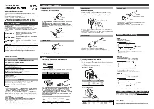
Pressure SensorOperation ManualPSE53#/54#/550/56#/57# SeriesThank you for purchasing an SMC PSE53#/54#/550/56#/57# Series Pressure Sensor.Please read this manual carefully before operating the product and make sure you understand its capabilities and limitations.Please keep this manual handy for future reference.To obtain the operation manual about this product, please refer to the SMC website (URL https://) or contact SMC directly.These safety instructions are intended to prevent hazardous situations and/or equipment damage.These instructions indicate the level of potential hazard with the labels of"Caution", "Warning" or "Danger". They are all important notes for safety and must be followed in addition to International standards (ISO/IEC) and other safety regulations.WiringOperatorSafety InstructionsNOTE•The direct current power supply to be used should be UL approved as follows:Circuit (of Class 2) which is of maximum 30 Vrms (42.4 V peak), with UL1310Class 2 power supply unit or UL1585 Class 2 transformer.•The product is a UL approved product only if it has a mark on the body.•Do not drop, hit or apply shock to the Pressure Sensor.•Do not pull the lead wire forcefully, or lift the product by pulling the lead wire.•Do not use in a place where the product could be splashed by oil or chemicals.•Wire correctly.•Do not perform wiring while the power is on.•Do not route wires and cables together with power or high voltage cables.•Be sure to ground terminal FG when using a commercially available switch-mode power supply.•When analogue output is used, install a noise filter (line noise filter, ferrite element, etc.) between the switch-mode power supply and this product.Specifications/Outline with DimensionsRefer to the product catalogue or SMC website (URL https://)for more information about the product specifications and outline dimensions.Note: Specifications are subject to change without prior notice and any obligation on the part of the manufacturer.© 2011-2022 SMC Corporation All Rights Reserved Akihabara UDX 15F, 4-14-1, Sotokanda, Chiyoda-ku, Tokyo 101-0021, JAPAN Phone: +81 3-5207-8249 Fax: +81 3-5298-5362URL https://Attaching the connector to the sensor wire•Strip the sensor wire as shown below.•Do not cut the insulation.•Check that the above preparation has been performed correctly, then part A shown should be pressed in by hand to make temporary connection.•Part A should then be pressed in using a suitable tool, such as pliers.•The e-con connector cannot be re-used once it has been fully crimped.In cases of connection failure such as incorrect order of wires or incomplete insertion, please use a new connector.•When connecting the sensor to the PSE200 or PSE300 series, use connector as listed below.•For information aboutconnectors please consult the manufacturerscatalogue.Controller and applicable sensorsConnecting/Disconnecting•When mounting the connector, insert it straight into the socket, holding thelever and connector body, and push the connector until the lever hooks into the housing, and locks.•When removing the connector, press down the lever to release the hook from the housing and pull the connector straight out.•PSE200A series (PSE5##)•PSE300series (PSE5##)PSE310series (PSE5##-28)•Insert the corresponding wire colour shown in the table into the pin number printed on the sensor connector, to the bottom.•Output specification•PSE5##Voltage output: 1 to 5 VOutput impedance: Approx. 1 kΩ•PSE57#-28Current output: 4 to 20 mAAllowable load impedance: 500 Ω or less (at 24 VDC)100 Ω or less (at 12 VDC)•PSE5#-28Current output: 4 to 20 mAAllowable load impedance: 500 Ω or less (at 24 VDC)100 Ω or less (at 12 VDC)∗: Install the load either on the LINE(+) or LINE(-) side.∗: The PSE53# and PSE54#series are not available with current output.Connecting the sensor cable•Insert the connector into the sensor, paying attention to the connector direction.•The sensor cable includes a connector cover to prevent the connector from falling out.•Install the connector cover to the sensor, rotating clockwise to lock.•To remove the sensor cable, rotate the connector cover anti-clockwise to release the lock, and remove connector cover. After removing the cover, pull out the connector.Piping connections•Cut the tube end perpendicular.•Insert the tubing to the sensor firmly for 8 mm or more from the end of the moulded pipe. The force necessary for piping insertion is approximately 25 N.•Insert the air tube for low pressure to Lo piping and the air tube for high pressure to Hi piping.Air tube (Applicable to I.D. 4)PSE53# seriesPSE550 series PSE54# seriesPSE56# seriesInternal circuit and wiring•When piping, apply a spanner to the piping section of the sensor.•Do not apply unnecessary forces such as twisting, pulling, moment loads, etc.on fittings or tubing.•When a tubing from a company other than SMC is used, ensure that the tubing has an internal diameter and tolerance of ø4±0.3 mm.•Applicable fluid is a fluid that does not corrode SUS316L.•When piping, apply a spanner to the piping section of the sensor.•To protect the sensor from water and dust, install an air tube to a safe area.PS ※※-OMO0006-C•Applicable fluid is a fluid that does not corrode C3604 + nickel plated,AI203 (aluminum oxide) and FKM.•When piping, apply a spanner to the piping section of the sensor.PSE57# series56∗: The pin numbers in the diagram indicate the PSE57#series 4 pin connector.All other series have 3 wires.∗: The pin numbers in the diagram indicate the PSE57#series 4 pin connector.。
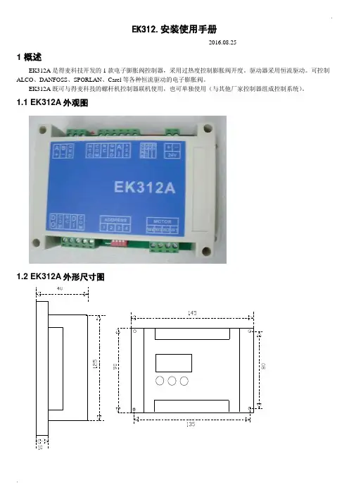
.EK312.安装使用手册-----2016.08.251 概述EK312A是得麦科技开发的1款电子膨胀阀控制器,采用过热度控制膨胀阀开度。
驱动器采用恒流驱动。
可控制ALCO、DANFOSS、SPORLAN、Carel等各种恒流驱动的电子膨胀阀。
EK312A既可与得麦科技的螺杆机控制器联机使用,也可单独使用(与其他厂家控制器组成控制系统)。
1.1 EK312A外观图1.2 EK312A外形尺寸图..1.3 EK312A 电气连接示意图EK312A电气连接示意图B-GA++-G TI DO W3W2W4AI +24G DI Com ComW1MotorB-GND A+ONOFF1234ON OFF1234O NO F FSW2JP2JP1JP3JP4JP5SW1VCCIout SW1地址1234OFF OFF 1ON OFF 2OFF ON 3ON ON4N LAC220VO N O FFSW212345V 10V举例1:12345123412312345612JP2-5设置为4-20mA输入O N O F FSW21234C V 5V 10V 举例2:JP2-5设置为0-10V输入O NO F FSW21234C V 5V 10V电子膨胀阀接线说明:ALCO膨胀阀:W4:白色W3:黑色W2:棕色W1:蓝色Danfoss膨胀阀:W4:黑色W3:白色W2:绿色W1:红色SPORLAN膨胀阀:W4:白色W3:黑色W2:绿色W1:红色Carel膨胀阀:W4:黄色W3:白色W2:棕色W1:绿色地址拔码说明:模拟输入拔码说明:报警输出启停开关电子膨胀阀24V电源输入压力传感器温度传感器通讯线运行故障通讯确认向上向下C V 0|10V0|5V 电压型电流型使用按键显示板备用注1:压力传感器接线:注2:压力传感器接线处,板内供电是24V ,如果传感器不是24V 供电,则要外接电源,之后将电源的负极接到板上的地(JP2-4)即可。
hapter 1 - Introduction第一章绪论1.1About this manual1.1 关于此手册This User Manual describes your new Measure Web Tension System. When you have read the manual, you will have the necessary knowledge for mechanical and electrical installation, commissioning, operation, preventive maintenance and basic fault tracing of your measurement system.。
该手册介绍新型幅面材料的张力测量系统,阅读该手册须具备对测量系统的认知,包括机械和电气安装、调试、操作、定期检修和基本故障查寻。
注:对于不同产业来说,幅面材料所指不同。
幅面在钢铁工业中是指带钢;纺织工业是指布匹;造纸工业是指纸张;塑料工业是指塑料薄膜……To get the best reliability and precision out of your measurement system, study this User Manual first.阅读用户手册可使你的测量系统获得最佳的可靠性和精密度。
1.2How to use this manual1.2 怎么使用手册This user manual comprises two main parts.此用户手册有两个主要部分。
rmation about the Tension Electronics:1. 张力传感器的信息。
-System and safety information (chapter 1)-系统和安全信息(第一章)-Installation, commissioning, maintenance, operation and fault tracing (chapters 2-6)-安装,试车,维护,操作和故障查寻(2-6章)-Technical data (appendix A)-技术数据(附录A)rmation about Designing the Load Cell Installation:压头的安装-Vertical-force sensing load cell PFCL 301E (Appendix B)微型垂直力压头PFCL 301E (附录 B)-Horizontal-force sensing load cell PFTL 301E (Appendix C)微型水平力压头PFTL 301E (附录 C)-Radial-force Tensiometer PFRL 101 (Appendix径向张力计PFRL 101(附录D)-Horizontal-force sensing load cell PFTL 101 (Appendix水平力压头PFTL 101 (附录 E)Each appendix contains detailed information about one of the above load cell types when used in web tension systems with Tension Electronics PFEA111/112.每个附录均包括上述幅面张力系统使用到的PFEA111/112测量装置的详细信息。
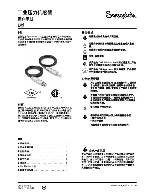
MS-CRD-PTI-ERev 2 11-08-WEL工业压力传感器用户手册 E 型E 型世伟洛克® (Swagelok)工业压力传感器可在各种各样的工业应用中提供系统压力的电子监测。
E 型传感器是被特殊设计用于满足需要防爆等级的工业应用对耐久性和性能的要求。
®引言世伟洛克工业压力传感器允许在各种工业应用中对系统压力进行电子监控。
该产品的精度为极限点校准量程的 0.5 %(最佳拟合直线量程的 0.25 %),且拥有温度补偿,能在温度波动的应用环境下确保准确性和长期稳定性。
传感器可提供各种压力连接,额定压力,压力单位和信号输出以满足众多应用需求。
■ 安全图标 ............................. 1■ 安全使用说明 ......................... 1■ 机械安装 ............................. 2■ 使用与维护 ........................... 2■ 电气安装 ............................. 2■ 接线图............................... 3■ FM 和CSA 认证 ....................... 3■ 故障排除指南 . (4)目录可能造成生命危险或严重伤害。
可能由于弹射出的部件造成生命危险或严重伤害。
可能由于高热的表面造成燃烧的危险。
注意,重要信息该产品由 CSA International 测试并鉴定。
产品在安全方面满足适用的加拿大标准。
该产品由FM Approvals 测试并鉴定。
产品在安全方面满足适用的美国标准。
警告警告警告安全图标为了正确和安全的使用,必须根据NEC 、适用的本地规范以及本说明安装、使用和维护世伟洛克 E 型 传感器。
否则,可能发生严重的人身伤害和损失。
传感器上的电子连接必须按照初始状态使用,不能添加旁路或修改。
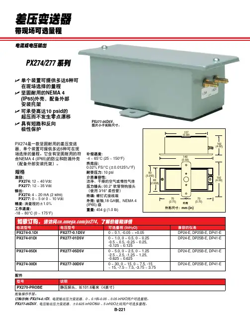
B-221差压变送器带现场可选量程U 单个装置可提供多达6种可在现场选择的量程U 坚固耐用的NEMA 4 (IP65)外壳,配备外部 安装托架U 可承受高达10 psid 的 超压而不发生零点漂移U 具有短路和反向 极性保护PX274是一款坚固耐用的差压变送器,单个装置可提供多达6种可在现场选择的量程。
它含有坚固耐用的符合NEMA 4 (IP65)的防尘和防溅外壳(配备外部安装托架)。
规格激励:PX274: 12 ~ 40 Vdc PX277: 12 ~ 35 Vdc 输出:PX274: 4 ~ 20 mA (2 wire) PX277: 0 ~ 5 or 0 ~ 10 Vdc 精度: 满量程的±1.0%工作温度:-18 ~ 80°C (0 ~ 175°F)补偿温度:-4 ~ 65°C (25 ~ 150°F)热效应:0.02% FS/°C (±0.0125%/°F)耐受压力: 10 psi 介质兼容性:洁净、干燥的空气或惰性气体压力接头: 00.2" 软管倒钩接头(使用 3⁄16" 柔性管)终端: 螺钉式接线端外壳: 被釉,18 GA 钢,NEMA 4 (IP65) 级重量: 454 g (1.0 lb)配备操作手册。
订购示例: PX274-0.1DI ,电流输出压力变送器,0 ~ 0.1和-0.05 ~ 0.05 inH2O 用户可选量程。
PX277-05D5V ,电压输出压力变送器,±0.625 inH2O 和0 ~ 5 inH2O 之间用户可选多量程。
PX277-05D5V , 图片小于实际尺寸。
PX274/277 系列电流或电压输出。
pg35压力传感器说明书中文版PG35压力传感器说明书感谢您选择使用PG35压力传感器。
本说明书将为您提供有关该产品的详细信息和正确使用方法。
在使用之前,请仔细阅读本手册,并按照说明进行操作。
1. 产品概述\nPG35压力传感器是一种高精度、高可靠性的压力测量设备。
它采用先进的传感技术,能够准确测量液体或气体的压力,并将其转化为电信号输出。
2.技术规格\n- 测量范围:0-1000kPa\n- 精度等级:±0.5%FS\n- 输出信号:4-20mA\n- 工作温度范围:-20℃至80℃\n- 电源电压:24VDC3. 安装和连接\n3.1 安装\n在安装PG35压力传感器之前,请确保安装环境干燥、清洁,并远离振动和冲击。
将传感器固定在需要测量压力的位置上,确保其与被测介质充分接触。
3.2 连接\n将传感器的电源线和信号线连接到相应的设备上。
请注意,电源线和信号线应正确连接,以免损坏设备。
4. 使用方法\n4.1 开机和校准\n在使用PG35压力传感器之前,请确保电源已连接并正常工作。
按下电源开关,传感器将开始工作。
为了确保测量的准确性,建议在使用前进行校准操作。
4.2 参数设置\nPG35压力传感器具有一些可调参数,如量程、输出信号等。
您可以根据实际需求进行相应的参数设置。
具体的设置方法请参考附带的参数设置手册。
5. 注意事项\n- 请勿将传感器暴露在过高或过低的温度环境中,以免影响其性能。
\n- 请勿将传感器接触腐蚀性液体或气体,以免损坏设备。
\n- 请勿随意拆卸或修理传感器,以免造成安全隐患或损坏设备。
\n- 请定期清洁传感器表面,并检查连接线路是否正常。
6. 常见问题解答\nQ: 为什么我的PG35压力传感器测量结果不准确?\nA: 可能是由于未正确校准或参数设置不正确导致的。
请参考说明书中的校准和参数设置部分进行操作。
Q: 我可以将PG35压力传感器用于测量液体和气体吗?\nA: 是的,PG35压力传感器适用于测量液体和气体的压力。

36智能电子式压力传感器说明书IP68模拟量输出RM-PA1140/50-PA41-CN-V1.147面板控制与显示功能特征Output 1滞后功能/N.O.(Hno)滞后功能/N.C.(Hnc)视窗功能/N.O.(Fno)视窗功能/N.C.(Fnc)Output 2模拟输出4~20 mA(I)模拟输出0~10 V(U)从压力传感器 探测到系统当前的压力,显示系统当前压力(bar ;Psi;kgf;MPa),同时根据设置输出状态,产生两个输出信号。
滞后作用如果系统压力与预设的差不多,那么滞后现象保持在输出平稳的状态。
当系统压力增大的时候,输出端能够达到打开开关的点(SP1);当系统压力再一次减小时,输出端能够达到关闭开关的点(rP1)。
滞后调整的方法:首先打开开关的点确定好,然后根据不同的要求再重新确定。
压力 通过视窗的作用能监测到明确的可以被接受的值。
当系统在开(SP1) 和关 (rP1) 之间变化时,输出接通 (视窗作用/常开) 或不接通 (视窗作用/常闭)。
通过 SP1 和 rP1的不同可以设定视窗的宽度。
SP1为上限值,rP1为下限值。
Psp rPt滞后Hno Hnc视窗功能101049运行模式(正常工作模式)·当外部提供电压时,装置为工作模式,根据它所设置的参数来监控和开关输出。
·模拟信号的输出值与系统压力有关。
·数码管显示表明当前系统的压力,红色二极管发光表示晶体管输出时开关的状态。
()·MODE/ENTER MODE/E 键键显示模式显示参数和设置参数值当很快按下“”键时,装置为参数值可读的显示模式,装置内部的进程和输出仍然为工作模式。
·每按一下“NTER”,就会出现一个参数名称。
·当快速按“LEARN/SET”时,对应的参数值显示5秒,5秒以后装置回到工作模式。
设置模式(参数值的设定)选择确定一个参数值后(显示模式),装置就会经过一个设置模式,一直按着“LEARN/SET”键直到显示的参数值改变, 装置的内部仍为工作模式。

压力传感器使用说明书1211131000/100110141100/11019158167176185194203212221一.仪表选型注1:标准型:仪表出厂前具有继电器输出和电压脉冲输出。
注2:如果仪表选串行通讯口,报警只能选该型号。
二.接线图电源报警2(-)AC90-260V (+)RS484报警3(-)通讯SSR 输出-(+)(D2)24V/20mA +电流互感器输入继电器AC5A 4-20mA 输出+报警1或热电偶PT100第二输出(带PD )安装尺寸(面板安装)1000/10011100/110150145+0.692+0.845+0.692+0.892+0.845+0.6深100mm深100mm深105mm注:为确保安装正确,请参阅英文版手册中的注意事项和警告。
三.功能说明1)输入种类热电偶:K、J、N、S、R、T热电阻:PT100电压:0-50mv,10-50mv电流:0-20mA,4-20mA,0-10mA(电流输入需在输入端并接2.5Ω或5Ω精密电阻)电流互感器输入2)输出输出1:继电器:端子额定电流5A/220VacSSR:24V/20mA电压脉冲DC输出:4-20mA输出2:用报警输出1,通过软件组态改为PD控制功能3)报警功能报警1可以带PD控制,触点电流5A报警2和3触点为常开,可以通过内部跳线改为常闭触点容量为3A/220Vac4)数字通讯(电流环/RS485)如果仪表有1200波特率无源电流环接口,接收二极管在端子8(RX+)和端子9(RX-)传输晶体管端子10(TX+)和(TX-)标准配置(并联到串行口)联接到二极管阻值为1千欧,集电极电阻为100Ω对串联连接,接到二极管阻值为100欧若配置为4线制RS485(1200波特率),输入端为8(RX+)和9(RX-)传输为10(TX+)和11(TX-)[参阅硬件组态]四.显示面板和按键说明A:显示测量值B:显示设定值1)显示过程设定值2)当AL1,AL2,AL3/HB灯闪烁时,设定报警值显示3)当字母“P”前面显示[0-99%]显示主输出功率4)可显示组态参数F:主输出灯,当第一输出动作时该灯亮G:报警输出指示C :功能键“F ”1)F 键用来选择设定值或报警值以便读取和修改设定值,如果未按住F 键,10秒钟后,修改值将自动存贮,同时返回显示过程设定值。
1Proximity Sensors Capacitive •Level control relay•Max.-min. control of charging/discharging •For use with refractive optical sensors or capacitive sensors•Controls liquid/granulate presence or absence with one sensor, or liquid/granulate level within max./min. limits with two sensors•Normal or inverted function selectable •10 A SPDT output relay •LED-indication: relay ON •AC or DC power supplyProduct DescriptionLevel control relay for trans-parent liquids or granulates which can control one or two levels of charging or dis-charging. For use with opti-cal sensors (VP ..) or capaci-tive sensors (DR.. or EC..).Open collector NPN-types only.Type SelectionPlug Output Supply: 24 VAC Supply: 115 VAC Supply: 230 VAC Supply: 24 VDC CircularSPDTSV 190 024SV 190 115SV 190 230SV 190 724Input SpecificationsType SV 190 (Charging/Discharging)Amplifier, Capacitive, OpticalSupply SpecificationsGeneral Specifications2Mode of OperationExample 1One sensor/one levelThe relay operates when the sensor is immersed and releases when the sensor is no longer immersed. When pins 7 and 8 are interconnect-ed (dotted line), the relay is inverted.Example 2: Discharging T wo sensors/two levels The relay operates when the upper sensor (max. level) is immersed and releases when the lower sensor (min. level) is no longer immersed. When pins 7 and 8 are interconnect-ed (dotted line), the relay is inverted.Example 3: Charging.T wo sensors/ two levels In fill-up applications inverted function (pins 7 and 8 connec-ted) should always be used and the pump alwalys be supplied through pin 3 (relay ON).The relays releases at desired max. level making the pump stop. In case of power supply interruptions, the relay releas-es and the pump stops, thus overflow is prevented.Sensor characteristicsThe optical sensors VP for li-quids must not be exposed to more than 100 lux from am-bient light sources.The capacitve sensors DR and EC are for solid, fluid or granulated substances. The activating distance depends on the physical and electrical characteristics of the object to be detected.Note: Solid or fluid conduc-tors are detected at a greater distance than light or porous insulators.Wiring DiagramsOutput SpecificationsSV 190Operation DiagramsExample 1Example 2 and 3AccessoriesSensors, open collector NPN-types:Optical: VPCapacitive: DR, EC BasesHold down spring Base coversFront mounting bezel。
压力传感器的使用指南说明书压力传感器使用指南说明书1. 引言压力传感器是一种用于测量压力变化并将其转换为电信号的设备。
本说明书旨在向用户提供关于压力传感器的详细信息以及正确使用和维护该设备的指南。
2. 压力传感器的工作原理压力传感器基于压电效应或德式效应,通过测量压力对感应电极产生的变化电荷或电阻进行压力测量。
该设备对于各种应用领域,如工业自动化、汽车工程、医疗监测等起着至关重要的作用。
3. 适用范围本款压力传感器适用于各种气体或液体介质的压力测量。
请在使用前仔细查阅技术规格表,确保其适用于目标应用环境的压力范围和介质。
4. 安装要求4.1 安装位置:为确保准确测量压力,请将传感器安装在位于压力变化区域的合适位置。
避免在振动、温度变化较大或受到冲击的环境中直接安装。
4.2 连接管路:根据应用需求,选择合适的管路和连接接头,并确保其与传感器连接紧固可靠,避免压力泄漏。
5. 连接和电气接线5.1 连接方式:根据用户需求,可选择扁平电缆连接或引线连接。
5.2 接线要求:用户在连接电源和信号输出时,请遵循正确的极性连接规则,确保传感器能够正常工作。
6. 使用注意事项6.1 温度限制:请确保传感器在规定的温度范围内工作,避免超出温度范围,以免影响设备的性能和寿命。
6.2 防尘与防水:传感器防护等级应根据实际需求选择,以确保设备在尘土、湿气等恶劣环境下的正常运行。
6.3 电磁干扰:请避免将传感器安装在具有强电磁辐射的设备附近,以免影响传感器的准确性。
6.4 震动与冲击:传感器对于颠簸、震动和冲击很敏感,请注意将其安装在稳定的位置,并采取适当的防护措施。
6.5 供电电压:在使用过程中,请确保传感器的电源电压与规定的供电电压相匹配,以免引起设备损坏。
7. 校准和维护7.1 校准:为保证测量的准确性和稳定性,建议定期对传感器进行校准。
请参考附带的校准操作手册执行校准。
7.2 维护:传感器在使用过程中需要定期清洁和维护。
EM500系列传感器用户手册关于手册型号产品类别EM500-CO2二氧化碳传感器EM500-LGT光照传感器EM500-PP管道压力传感器EM500-PT100PT100温度传感器EM500-SMTC土壤传感器EM500-SWL投入式液位传感器EM500-UDL超声波测距传感器安全须知为保护产品并确保安全操作,请遵守本使用手册。
如果产品使用不当或者不按手册要求使用,本公司概不负责。
严禁改装本产品。
请勿将产品放置在不符合工作温度、湿度等条件的环境中使用,远离冷源、热源和明火。
请勿使产品受到外部撞击或震动。
本产品不可作为计量工具使用。
拆卸防水外壳时请勿遗漏内部的电子元件。
请勿将产品电池装反,否则可能导致产品烧坏。
为了您的设备安全,请及时修改设备默认密码(123456)。
产品符合性声明EM500系列符合CE,FCC和RoHS的基本要求和其他相关规定。
版权所有©2011-2022星纵物联保留所有权利。
如需帮助,请联系星纵物联技术支持:邮箱:*********************电话:************传真:************总部地址:厦门市集美区软件园三期C09栋深圳:深圳市南山区高新南一道TCL大厦A709文档修订记录日期版本描述2020.6.30V1.0第一版2020.8.26V1.1新增CO2,LGT,PP传感器和配置示例2020.9.25V2.0版式替换2021.12.30V2.1更新品牌Logo目录一、产品简介 (4)1.1产品介绍 (5)1.2产品亮点 (5)二、产品结构介绍 (5)2.1包装清单 (5)2.2外观概览 (6)2.2.1主机 (6)2.2.2传感器 (6)2.3产品尺寸(mm) (7)三、使用准备和安装 (7)3.1绝缘片拆卸 (7)3.2传感器安装 (7)四、开关和重置 (8)五、产品配置 (9)5.1手机APP配置 (9)5.1.1开关与基本读写配置 (9)5.1.2批量配置 (10)5.2电脑软件配置 (12)5.2.1开关与基本读写配置 (12)5.2.2批量配置 (14)5.2.3产品升级 (15)5.3配置示例 (15)5.3.1LoRaWAN频率设置 (15)5.3.2告警设置 (16)六、产品安装 (17)6.1壁挂式安装 (17)6.2抱杆式安装 (17)6.3DIN导轨式安装 (18)七、数据通信格式 (18)八、星纵云管理 (18)8.1星纵云注册 (18)8.2添加星纵网关 (18)8.3添加EM500到星纵云 (20)一、产品简介1.1产品介绍EM500系列室外环境监测传感器由星纵物联自主研发和设计,涵盖温度、距离、土壤等多种环境监测使用的传感器,采用IP67高防护等级防水防尘外壳,适用于各种恶劣外部环境。
Model 102BICP® Pressure SensorInstallation and Operating ManualFor assistance with the operation of this product, contact PCB Piezotronics, Inc.Toll-free: 800-828-884024-hour SensorLine: 716-684-0001Fax: 716-684-0987E-mail:************Web: The information contained in this document supersedes all similar information that may be found elsewhere in this manual.Service –Due to the sophisticated nature of the sensors and associated instrumentation provided by PCB Piezotronics, user servicing or repair is not recommended and, if attempted, may void the factory warranty. Routine maintenance, such as the cleaning of electrical connectors, housings, and mounting surfaces with solutions and techniques that will not harm the physical material of construction, is acceptable. Caution should be observed to ensure that liquids are not permitted to migrate into devices that are not hermetically sealed. Such devices should only be wiped with a dampened cloth and never submerged or have liquids poured upon them.Repair –In the event that equipment becomes damaged or ceases to operate, arrangements should be made to return the equipment to PCB Piezotronics for repair. User servicing or repair is not recommended and, if attempted, may void the factory warranty.Calibration –Routine calibration of sensors and associated instrumentation is recommended as this helps build confidence in measurement accuracy and acquired data. Equipment calibration cycles are typically established by the users own quality regimen. When in doubt about a calibration cycle, a good “rule of thumb” is to recalibrate on an annual basis. It is also good practice to recalibrate after exposure to any severe temperature extreme, shock, load, or other environmental influence, or prior to any critical test.PCB Piezotronics maintains an ISO- 9001 certified metrology laboratory and offers calibration services, which are accredited by A2LA to ISO/IEC 17025, with full traceability to SI through N.I.S.T. In addition to the normally supplied calibration, special testing is also available, such as: sensitivity at elevated or cryogenic temperatures, phase response, extended high or low frequency response, extended range, leak testing, hydrostatic pressure testing, and others. For information on standard recalibration services or special testing, contact your local PCB Piezotronics distributor, sales representative, or factory customer service representative.Returning Equipment –Following these procedures will ensure that your returned materials are handled in the most expedient manner. Before returning any equipment to PCB Piezotronics, contact your local distributor, sales representative, or factory customer service representative to obtain a Return Warranty, Service, Repair, and Return Policies and Instructions Materials Authorization (RMA) Number. This RMA number should be clearly marked on the outside of all package(s) and on thepackinglist(s) accompanying the shipment. A detailed account of the nature of the problem(s) being experienced with the equipment should also be included inside the package(s) containing any returned materials.A Purchase Order, included with the returned materials, will expedite the turn-around of serviced equipment. It is recommended to include authorization on the Purchase Order for PCB to proceed with any repairs, as long as they do not exceed 50% of the replacement cost of the returned item(s). PCB will provide a price quotation or replacement recommendation for any item whose repair costs would exceed 50% of replacement cost, or any item that is not economically feasible to repair. For routine calibration services, the Purchase Order should include authorization to proceed and return at current pricing, which can be obtained from a factory customer service representative.Contact Information –International customers should direct all inquiries to their local distributor or sales office. A complete list of distributors and offices can be found at . Customers within the United States may contact their local sales representative or a factory customer service representative. A complete list of sales representatives can be found at . Toll-free telephone numbers for a factory customer service representative, in the division responsible for this product, can be found on the title page at the front of this manual. Our ship to address and general contact numbers are:PCB Piezotronics, Inc.3425 Walden Ave.Depew, NY14043 USAToll-free: (800) 828-884024-hour SensorLine SM: (716) 684-0001 Website: E-mail:************PCB工业监视和测量设备 - 中国RoHS2公布表CHINA RoHS COMPLIANCEDOCUMENT NUMBER: 21354 DOCUMENT REVISION: D ECN: 46162Drawing Number: 21075Revision: CECN Number: 47023 1.0 INTRODUCTIONThis series of miniature dynamic pressure sensors is specifically designed for shock tube and blast wave measurements and for other applications requiring very high frequency, near non-resonant response.The term used to describe the transient response of this model series is “Frequency Tailoring” and it encompasses several mechanical and electrical design features coupled with stringent in-process fabrication/test procedures with heavy emphasis on the shock tube as a tool.2.0 DESCRIPTIONAlthough this series consists of sensors with three basic mechanical configurations and six different sensitivities, each model is basically similar in internal design.Typical ICP ® Probe Style SensorEach utilizes the acceleration-compensated Series 113 quartz piezoelectric element coupled to a source follower type miniature electronics. (See “General Guide to ICP ® Instrumentation,” G -0001B, for a detailed description of the ICP ® concept.)The figure above shows the components of the basic ICP ® probe, i.e. the piezoelectric element and the ICP ® source follower amplifier. These components are joined together as an inseparable sealed assembly at the factory. Disassembly should not be attempted in the field. Series 113B2x are in a probe configuration and are installed with a hollow clamp nut with 5/16-24 external threads. The housing of these models is at electrical ground potential. Series 113B3x are similar to the B2x Series with an additional feature; all Invar construction. The all Invar sensors are designed to have minimal susceptibility to thermal transient events and are specifically suited for high-temperature shock and blast measurements. Series 113: Probe Style Sensor Series 102 consist of the basic 113 Series probe, as in the above mentioned series, mounted in a 3/8-24 threaded mounting adaptor. The probe is installed at the factory in an "off ground" configuration, i.e. the probe body is insulated from the external mounting adaptor body. The Model 102A12 utilizes the same inner probe design as the above two designs but in a 3/8-24Seal Ring Potting Preload SleeveElectrodes 0.218DiaQuartz AccelerationMass and Mounting Clamp NutDrawing Number: 21075Revision: CECN Number: 47023 adjustment of diaphragm mounting depth where it is necessary to adapt to various wall thicknesses. These models are supplied only as low-pressure (250 psi and 100 psi) sensors and are also "off ground".Models 102A21 and 102A22 are high-temperature ICP ® versions to 400 ︒F (204 ︒C), with a 3/8-24 straight threads adaptor and 1/8-27 NPT adaptor, respectively.Series 102: Thread Mount Design, Ground-Isolated Sensor3.0 INSTALLATIONThis manual contains outline and installation information for your specific model.Prepare mounting ports in accordance with instructions given in specific installation drawings, paying particular attention to sealing surfaces. These surfaces must be smooth and free from chatter marks, nicks and other irregularities which could preclude a pressure tight seal.To fully realize the high-frequency response capabilities of this sensor series, flush mounting of the diaphragm must be used.In some cases, where flash temperatures such as those generated by blasts and shock fronts are present, it may be necessary to thermally insulate the diaphragm to minimize signals generated by these effects.be an effective insulating material in many cases. One or more layers may be used across the end of diaphragm and adaptor. A silicone rubber coating approximately .010” thick has also been proven effective in many applications. General Electric RTV type 106 is recommended. Apply the rubber coating to the surface of the diaphragm and allow it to cure in accordance with the manufacturer’s instructions. (If you have ordered the CA option, ablative coated models, further protection will not be necessary.) Although ICP ® sensors have low-output impedance and in general are not affected by moisture, in extreme environments it is good practice to protect cable connections with shrink tubing. It is not necessary to use low-noise cable with this sensor series. In fact, an optional Model 070B09 Solder Connector Adaptor allows the use of ordinary two-wire cable if desired. 4.0 OPERATION It is only necessary to supply the sensor with a 2 to 20 mA constant current at +20 to +30 VDC through a current-regulating diode or equivalent circuit. (See guide G-0001B for powering and signal utilization information pertaining to all ICP ® instrumentation). Most of the signal conditioners manufactured by PCB have an adjustable current feature allowing a choice of input currents from 2 to 20 mA. In general, for lowest noise (best resolution), choose the lower current ranges. For driving long cables (to several thousand feet), use higher current, up to 20 mA maximum. To operate system using a PCB signal conditioner: 1. Switch power on. 2. Wait several minutes for the IC ampli- fier to turn on and stabilize. 3. Proceed with measurements.Drawing Number: 21075Revision: CECN Number: 47023 5.0 POLARITYThe sensors in this series produce a positive-going output voltage for increasing pressure input.6.0 LOW-FREQUENCY RESPONSEThe low-frequency response of an ICP ® system is determined by:1. The discharge T.C. of the sensor2. If AC-coupled at power unit, the coupling time constant.Consult Section 7.0 in guide G-0001B detailed explanation of low-frequency characteristics of ICP ® instruments.7.0 HIGH-FREQUENCY RESPONSEFrequency tailoring and the very high-natural frequency of the sensor give an extremely wide usable frequency range (beyond 100 kHz). Exceptionally fast response time (1 µsec) and clean, virtually non-resonant response to rapid step functions are also features of these sensors. As mentioned previously, the diaphragm must be flush-mounted to fully realize the high-frequency response capabilities of this series.8.0 CALIBRATIONPiezoelectric sensors are dynamic devices, but static calibration means can be employed if discharge time constants are sufficiently long. Generally, static methods are not employed below several hundred seconds time constant.To employ static means, direct couple the sensor to the DVM readout using a T-Connector from the sensor jack or use the Model 484B in the calibrate mode. Apply pressure with dead weight tester and take readings quickly. Release pressure after each calibration point.For the shorter time constant, rapid step functions of pressure are generated by a pneumatic pressure pulse recorder or storage oscilloscope. PCB offers a complete calibration service. Consult factory for details. ICP is a registered trademark of PCB Piezotronics。