ECOTTER压力传感器TG-30B说明书
- 格式:pdf
- 大小:2.51 MB
- 文档页数:2
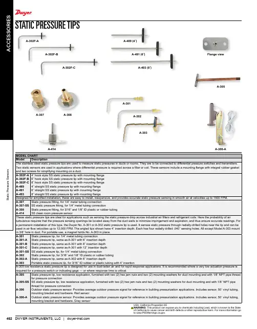
ECS SeriesCurrent SensorAvailable Models:SensorType . . . . . . . . . . . . . . . . . . . . . . . . . . . . . . . . .Toroidal through hole wiringMode . . . . . . . . . . . . . . . . . . . . . . . . . . . . . . . .Over or undercurrent, switch selectable on the unit or factory fixedTrip Point Range . . . . . . . . . . . . . . . . . . . . . .0.5 - 50A in 3 adjustable ranges or fixed Tolerance Adjustable . . . . . . .Guaranteed rangeFixed . . . . . . . . . . . .0.5 - 25A: 0.5A or ±5% whichever is less; 26 - 50A: ±2.5%Maximum Allowable Current . . . . . . . . . . .Steady – 50A turns; Inrush – 300A turns for 10s Trip Point Hysteresis . . . . . ... . . .. . . . . . . .≅ ±5%Trip Point vs. Temperature . . . . . . . . . . . . .±5%Response Time . . . . . . . . . . . . . . . . . . . . . . . .≤ 75ms Frequency . . . . . . . . . . . . . . . . . . . . . . . . . . . .45/500 Hz Type of Detection . . . . . . . . . . . . . .. . . . . . . .Peak detection Trip DelayType . . . . . . . . . . . . . . . . . . . . . . . . . . . . . . . . .AnalogRange Adjustable . . . . . . . . . .0.150 - 7s; 0.5 - 50s (guaran teed ranges) Factory Fixed . . . . . . .0.08 - 50s (±20ms, whichever is greater)Delay vs. Temperature . . . . . . . . . . . . . . . . .±15%Sensing Delay on Startup . . . . . . . . . . . . . . .Factory fixed 0 - 6s: +40%, -0%InputVoltage . . . . . . . . . . . . . . . . . . . . . . . . . . . . . . . 24 , 120, or 230VAC; 12 or 24VDCTolerance 12VDC & 24VDC/AC . . . . . .-15 - 20% 120 & 230VAC . . . . . . . . . . . . .-20 - 10% AC Line Frequency . . . . . . . . . . . . . . . . . . . .50/60 Hz OutputType . . . . . . . . . . . . . . . . . . . . . . . . . . . . . . . . .Electromechanical relay Form . . . . . . . . . . . . . . . . . . . . . . . . . . . . . . . . .Isolated, SPDTRating . . . . . . . . . . . . . . . . . . . . . . . . . . . . . . .10A resistive @ 240VAC; 1/4 hp @ 125VAC; 1/2 hp @ 250VACLife . . . . . . . . . . . . . . . . . . . . . . . . . . . . . . . . . .Mechanical – 1 x 10⁶ ; Electrical – 1 x 10⁵ProtectionCircuitry . . . . . . . . . . . . . . . . . . . . . . . . . . . . .EncapsulatedIsolation Voltage . . . . . . . . . . . . . . . . . . . . . .≥ 2500V RMS input to output Insulation Resistance . . . . . . . . . . . . . . . . . . .≥ 100 MΩ MechanicalMounting . . . . . . . . . . . . . . . . . . . . . . . . . . . .Surface mount with two #6 (M3.5 x 0.6) screws Dimensions . . . . . . . . . . . . . . . . . . . . . . . . . . .3.5 x 2.5 x 1.75 in. (88.9 x 63.5 x 44.5 mm)Termination . . . . . . . . . . . . . . . . . . . . . . . . . .0.25 in. (6.35 mm) male quick connect terminals (5)EnvironmentalOperating / Storage Temperature . . . . . . .-40° to 60°C / -40° to 85°C Humidity . . . . . . . . . . . . . . . . . . . . . . . . . . . . .95% relative, non-condensing Weight . . . . . . . . . . . . . . . . . . . . . . . . . . . . . . .≅ 6.4 oz (181 g)Features:• Toroidal through hole wiring • 0.5 - 50A trip points• Adjustable or factory fixed trip delays • Isolated, 10A, SPDT output contacts • 5% trip point hysteresis (dead band)Approvals:Auxiliary Products:• Female quick connect: P/N: P1015-13 (AWG 10/12)P/N: P1015-64 (AWG 14/16) P/N: P1015-14 (AWG 18/22)SpecificationsOrder Table:XSeries─ECS - Selectable over or undercurrent sensing ─ECSH - Overcurrent sensing ─ECSL - Undercurrent sensingXInput─1 - 12VDC ─2 - 24VAC ─3 - 24VDC ─4 - 120VAC ─6 - 230VACXTrip Point─Fixed - Specify 2-50A in 1A increments─0 - 0.5-5A adjustable ─1 - 2-20A adjustable ─H - 5-50A adjustableXTrip Delay─F - Specify: 0.08-50s factory fixed─A - 0.150-7s adjustable ─B - 0.5-50s adjustableXSensing Delay on Start Up─Blank - 0s ─C - 1s ─D - 2s ─E - 3s ─F - 4s ─G - 5s ─H - 6sECS20BC ECS21BC ECS21BH ECS2HBC ECS30AC ECS40A ECS40AC ECS40BC ECS40BD ECS41A ECS41AC ECS41BC ECS41BD ECS41BH ECS41F.08ECS4HBC ECS4HBH ECS60AH ECS60BC ECS61BC ECS6HAHECSH21F.08C ECSH30AC ECSH3HF0.08D ECSH40AC ECSH40AD ECSH41AD ECSH41BC ECSH41F.08D ECSH4HF.08D ECSH61AD ECSL31A ECSL40AC ECSL40B ECSL40BH ECSL41A ECSL41AD ECSL45F7ECSL4HBH ECSL61AH ECSL6HAC The ECS Series of single-phase AC current sensors is a universal, overcurrent or undercurrent sensing control. Its built-in toroidal sensor eliminates the inconvenience of installing a stand-alone current transformer. Includes onboard adjustments for current sensing mode, trip point, and trip delay. Detects over or undercurrent events like; locked rotor, loss of load, an open heater or lamp load, or proves an operation is taking place or has ended.For more information see:Appendix B, page 166, Figure 20 for dimensional drawing.Appendix C, page 169, Figure 17 for connection diagram.OperationInput voltage must be supplied at all times for proper operation. When a fault is sensed throughout the trip delay, the output relay is energized. When the currentreturns to the normal run condition or zero, the output and the delay are reset. If a fault is sensed and then corrected before the trip delay is completed, the relay will not energize and the trip delay is reset to zero.AdjustmentSelect the desired function, over or under current sensing. Set the trip point and trip delay to approximate settings. Apply power to the ECS and the monitored load. Turn adjustment and watch the LED. LED will light; turn slightly in opposite direction until LED is off. Adjustment can be done while connected to the control circuitry if the trip delay is set at maximum. To increase sensitivity, multiple turns may be made through the ECS’s toroidal sensor. The trip point range is divided by the number of turns through the toroidal sensor to create a new range. When using an external CT, select a 2VA, 0-5A output CT rated for the current to be monitored. Select ECS adjustment range 0. Pass one secondary wire lead through the ECS toroid and connect the secondary leads together.If desired part number is not listed, please call us to see if it is technically possible to build .NC = Normally Closed Contact A = Sensing Delay On Start Up TD = Trip DelayR = ResetOC = Monitored Cur rentAFFB9L; HLMU; SCR9LLLC4; LLC6; PLSECS; ECSWAppendix B - Dimensional DrawingsFIGURE 15FIGURE 16FIGURE 18DCSAFIGURE 22inches (millimeters)(ECS has spade connectors andECSW has terminal board)FIGURE 15 - HLV Series FIGURE 16 - KVM SeriesV = VoltageL = LEDS = Undervoltage SetpointNO = Normally OpenNC = Normally ClosedC = Common, Transfer ContactL1N/L2FIGURE 17 - ECS SeriesV = VoltageI> = OvercurrentI< = UndercurrentFIGURE 18 - ECSW SeriesMC = Motor ContactorM = MotorF = FusesOL = OverloadRSW = Reset SwitchPositiveSwitchingNegativeSwitchingSinkingSourcingFIGURE 19 - TCS SeriesFIGURE 20 - TCSA SeriesZ = Zero AdjustS = Span AdjustW = Insulated Wire Carrying Monitored CurrentPLC = PLC Analog Input or Meter InputAppendix C - Connection DiagramsW = Insulated WireCarrying Monitored CurrentRelay contacts are isolated .FSW = Fan or Float ContactsCR = Control RelayCS = Current SensorMCC = Motor Contactor CoilI> = Adjustable OvercurrentI< = Adjustable UndercurrentW = Monitored Wire∆T - Adjustable Trip DelayL = LoadV = VoltagePS = Power SupplyPLC = PLC Digital Input Module。

Low-power cellular sensor gateway for wireless drop-in networking to remotely monitor industrial environments and control systemsApplicationBattery-powered remote cellular monitoring of connected 4 to 20 mA analog as well as digital field devices via mobile communications.•Remote monitoring and visualization of any process variable measured in the field regardless of location•Especially great for controlling the inventory in typical 3-times-a-day measuring •Flexible for battery use on remote places or powered by DC •Configuration of measuring and transmission cycles•Four 4 to 20 mA input channels, one digital input for wake up special condition •Modbus RS485 input for up to 4 slaves (FXA30B)Your benefits•Simple configuration of Fieldgate via Machine-to-Machine communication service from Endress+Hauser•Specially useful for remote locations due to a long-lasting battery•External, configurable power outputs eliminate the need for sensor power supplies •Weatherproof enclosure with wide temperature range makes it ideal for use in all environements•Configurable read and uplink intervals•LTE (USA, Canada and Mexico only) or 3G penta band cellular module for global communication•Optional available with bundled cellular serviceProducts Solutions ServicesTechnical Information Connect Sensor FXA30,FXA30BFieldgateTI01356S/00/EN/03.20715099652020-12-14Connect Sensor FXA30, FXA30B2Endress+HauserTable of contentsImportant document information (3)Symbols for certain types of information ..............3Symbols in graphics . (3)Terms and abbreviations (4)Registered trademarks .......................5Function and system design ...................5Use cases .................................6Point to point remote monitoring ..................6Up to 4 × point to point remote monitoring (7)Input (8)Analog ....................................8Digital . (8)Output ...................................9Digital output ................................9Power output .. (9)Power supply .............................10Power options (10)Installation (11)Mounting ..................................11Antenna . (12)Environment ..............................13Mechanical construction ....................14Dimensions ................................14Weight ...................................14Materials . (14)Operability (15)Operating concept (15)Certifications .............................15RF exposure statement .........................15FCC certifications and regulatory information ..........15UL/cUL conformity (16)Ordering information (17)Connect Sensor FXA30.........................17Connect Sensor FXA30B ........................18XD87DC – FXA30 Data communication service (18)Accessories ...............................19Supplementary documentation ...............20Standard documentation (20)Connect Sensor FXA30, FXA30BEndress+Hauser 3Important document informationSymbols in graphicsConnect Sensor FXA30, FXA30BTerms and abbreviations4Endress+HauserConnect Sensor FXA30, FXA30BEndress+Hauser 5Registered trademarksDIGI ©Digi, Digi International, and the Digi logo are trademarks or registered trademarks in the United States and other countries worldwide of Digi International Inc.Modbus TMRegistered trademark of Schneider Electric USA, Inc.Internet Explorer 11Registered trademark of the MICROSOFT CORPORATION.Firefox®Registered trademark of of the Mozilla Foundation Chrome™Registered trademark of Google Inc.All other trademarks mentioned in this document are the property of their respective owners.Function and system designConnect Sensor FXA30/FXA30B is a low-power cellular sensor gateway for wireless drop-in networking to remotely monitor industrial environments and control systems, such as inventorylevel, flow, pressure as well as any other process variable. To power Connect Sensor FXA30/FXA30B,use either the internal battery or an external power source, such as solar panels, for setups with no power or limited power. Connect Sensor FXA30/FXA30B includes an external input/output (I/O)interface inside a waterproof enclosure for connecting sensors. The sensors gather information (sensor readings) from their environment, and Connect Sensor FXA30/FXA30B reports thatinformation to SupplyCare Hosting using a lowbandwidth cellular connection.Make sure there is adequate cellular network coverage where you plan to install the gatewaybefore purchasing cellular service.Connect Sensor FXA30, FXA30B6Endress+HauserUse casesPoint to point remote monitoringConnect Sensor FXA30/FXA30B (battery and/or mains powered) can connect 1 sensor to SupplyCare Hosting using 4 to 20 mA analogue communication.1Sensor2Connect Sensor FXA30/FXA30B 3Battery and/or mains power 4Antenna5SupplyCare HostingConnect Sensor FXA30, FXA30BEndress+Hauser 7Up to 4 × point to point remote monitoring Connect Sensor FXA30/FXA30B (battery and/or mains powered) can connect up to 4 sensors to SupplyCare Hosting using 4× 4 to 20 mA analogue communication.1Sensor2Connect Sensor FXA30/FXA30B 3Battery and/or mains power 4Antenna5SupplyCare HostingConnect Sensor FXA30, FXA30B8Endress+HauserInputAnalogCurrent loopConnect Sensor FXA30/FXA30B can monitor a current input from 4 to 20 mA from up to 4 devices.Current range: 4 to 22 mA (Current loop input)Modbus RS-485 - Connect Sensor FXA30BConnect Sensor FXA30B can monitor up to 4 Modbus-enabled external sensors.Biasing and termination are needed when a Modbus sensor is connected on a long wiring harness and the sensor does not provide its own termination and biasing. Termination is only applied at the two ends of the 485 bus (not in the middle), and bias typically is applied only once on the whole bus.For detailed information about implementing Modbus over a serial line, refer to the Modbus documentation at .DigitalWhen configuring the digital I/O pin as a digital input, it allows the following modes of operation:Input modeConnect Sensor FXA30/FXA30B gets the digital input value at scheduled sensor readings. You can configure it to send an alarm report for specific input values or when an input value changes. You can also configure Connect Sensor FXA30/FXA30B to wake from sleep mode when an input value changes (rising edge or falling edge wake).Input Range:•0 to 0.6 V DC logic low •2.2 to 30 V DClogic highMax. input voltage 30 V DCPulse counterConnected to a mechanical meter, Connect Sensor FXA30/FXA30B counts pulses duringConnect Sensor FXA30/FXA30B sleep cycles and reports them to SupplyCare Hosting during normal reporting intervals.Max. pulse count frequency 2 kHzConnect Sensor FXA30, FXA30BEndress+Hauser 9OutputDigital outputWhen configuring the digital I/O pin as a digital output, it is an open collector output with an optional pull-up resistor. A self-resetting fuse limits the maximum collector current to 750 mA.Power outputConnect Sensor FXA30/FXA30B can power up to 4 sensors using the analog, digital, or serial power outputs.•The sensor power output voltage is 24 V DC•The maximum output current for each sensor power output connector is 200 mA.When using continuous monitoring, the combined maximum output current for ALL sensors is 200 mA.Connect Sensor FXA30, FXA30B10Endress+HauserPower supplyPower optionsPower the Connect Sensor FXA30/FXA30BWhile Connect Sensor FXA30/FXA30B has an internal battery for power, you can use an external power source, such as solar panels or other DC sources. For an external power source, use theexternal power input to power the Connect Sensor FXA30/FXA30B device.•When Connect Sensor FXA30/FXA30B is connected to an external power source, theexternal power source becomes the primary power source and the internal battery becomes a backup power source.If the external power source is unable to power Connect Sensor FXA30/FXA30B (such as when it has an unacceptable voltage range), it automatically switches to the internal battery as the power source.•The external power inputs accept a DC range of 8 to 30 V DCPower the sensorsThe Connect Sensor FXA30/FXA30B can power sensors connected to the analog, digital, or serial power outputs. In order to configure the Connect Sensor FXA30/FXA30B power options the cloudinterface on the Field Information Server is to be used.If you have a Modbus-enabled device that must get power from theConnect Sensor FXA30B,the Modbus device must be wired to the serial power output.Note the following:•The sensor power output voltage is 24 V DC•The maximum output current for each sensor power output connector is 200 mAInstallationMounting Wall mountinge Mounting kit Connect Sensor FXA30/FXA30B and fix the 4 brackets with the suppliedscrews on backside of the housing.1BacksideThe Mounting kit Connect Sensor FXA30/FXA30B can be ordered as accessory via Ordercode : 713369752.Only to be fastened at stable materials (e.g. metal, brick, concrete) using suitable fasteningmaterial (to be supplied by customer).Endress+Hauser1112Endress+HauserAntennaConnect Sensor FXA30/FXA30B require an external antenna for wireless communication via UMTS (2G/3G) or LTE (North America).If Connect Sensor FXA30/FXA30B is mounted inside a cabinet, the antenna must be mounted outside the cabinet.Suitable antennas are available as an accessory → 19.In areas with weak UMTS (2G/3G) or LTE (North America) reception, it is advisable to first check the communication before securing the antenna permanently.3Connection: SMA connection1UMTS (2G/3G) or LTE network2Antenna for Connect Sensor FXA30/FXA30B 3SMA connection4Connect Sensor FXA30/FXA30B 5Control cabinetEnvironmentEnvironmental Operating temperature–35 to +70 °C (–31 to 158 °F)Storage temperature–40 to +85 °C (–40 to 185 °F)Relative humidity90% (Non-condensing after 90%)Ingress Protection (IP) rating IP66Endress+Hauser1314Endress+HauserMechanical construction4Dimensions in mm (in)WeightMaterialsOperabilityOperating concept Connect Sensor FXA30/FXA30B is a communication gateway that will exclusively work togetherwith SupplyCare Hosting from Endress+Hauser. It is not a stand alone Gateway solution andtherefore the purchase of SupplyCare Hosting visualization has to be foreseen.Configuration and management•Endress+Hauser Field Information Server (FIS)•Local USB to Serial CLI ProtocolProtocol TCPSIM Slots1, standard sizeHardware enhancementsAditional to the features of the Connect Sensor FXA30 the Connect Sensor FXA30B is equipped withthe following functions:Modbus protocol (RS485 serial)Data storage•Standard-Firmware:In case of problems with the uplink mobile connection, the Connect Sensor FXA30B can store themeasured data of up to 63k data points.•Continuous Monitoring Firmware:Connect Sensor FXA30B can store 5 minutes of measured data (resolution 1 second) before andafter an alarm event.CertificationsThe following certifications apply to the Connect Sensor FXA30/FXA30B device.RF exposure statement In order to comply with RF exposure limits established in the ANSI C95.1 standards, ensure usersmaintain a distance from the product of no less than 200 mm (7.87 in).FCC certifications and regulatory information Radio frequency interface (RFI) (FCC 15.105)This device has been tested and found to comply with the limits for Class B digital devices pursuant to Part 15 Subpart B, of the FCC rules. These limits are designed to provide reasonable protection against frequency energy, and if not installed and used in accordance with the instruction manual, may cause harmful interference to radio communications. However, there is no guarantee that interference will not occur in a particular installation. If this equipment does cause harmful interference to radio or television reception, which can be determined by turning the equipment off and on, you are encouraged to attempt to correct the interference with one or more of the following measures:•Reorient or relocate the receiving antenna.•Increase the separation between the equipment and receiver.•Connect the equipment to an outlet on a different circuit from the receiver.•Consult the dealer or an experienced radio/TV technician for help.Labeling requirements (FCC 15.19)This device complies with Part 15 of FCC rules. Operation is subject to the following two conditions: (1) this device may not cause harmful interference, and (2) this device must accept any interference received, including interference that may cause undesired operation.If the FCC ID is not visible when the unit is installed inside another device, then the outside of the device into which the module is installed must also display a label referring to the enclosed module FCC ID.Modifications (FCC 15.21)Changes or modifications to this equipment not expressly approved by Digi may void the user’s authority to operate this equipment.Endress+Hauser15UL/cUL conformity Conformity to UL / cUL standards in the United States and Canada is in accordance with thefollowing:16Endress+HauserEndress+Hauser 17Ordering informationDetailed ordering information is available from the following sources:•In the Product Configurator on the Endress+Hauser website: -> Click "Corporate"-> Select your country -> Click "Products" -> Select the product using the filters and search field ->Open product page -> The "Configure" button to the right of the product image opens the Product Configurator.•From your Endress+Hauser Sales Center:Product Configurator - the tool for individual product configuration •Up-to-the-minute configuration data•Depending on the device: Direct input of measuring point-specific information such as measuring range or operating language •Automatic verification of exclusion criteria•Automatic creation of the order code and its breakdown in PDF or Excel output format •Ability to order directly in the Endress+Hauser Online ShopConnect Sensor FXA30Connect Sensor FXA30 is an unstructured product and each one of its options contains the included properties:Order No. explained - what is included?Connect Sensor FXA30B Connect Sensor FXA30B is a structured product and can be ordered via Product Configurator→ 17XD87DC – FXA30 Data communication service Cellular Data Communication Service Agreement for Connect Sensor FXA30/FXA30B is a service level agreement to provide the data communication via cellular network forConnect Sensor FXA30/FXA30B fieldgates.With the new fieldgate Connect Sensor FXA30/FXA30B we support the process of Inventory Control to gather data from the E+H measuring devices and forwarding it to SupplyCare Hosting.The XD87DC – Connect Sensor FXA30/FXA30B Data communication service is the contract setup of the data communication for the Connect Sensor FXA30/FXA30B.XD87DC – Cell. Data Communication (12 months)For order options A and B, the monthly use of data is set to 1 MB of data (Order options A and B), enough to cover the following use cases:•3 measurements + 1 uplink (per day)•3 measurements + 3 uplinks (per day)•24 measurements + 3 uplinks (per day)For customers that need more frequent uplinks than the mentioned above the Y option can be used on request.Before ordering a bundled data communication service or if there are any doubts on thecoverage or the cellular network footprint, please always check before ordering. Detailedordering information is available from your Endress+Hauser Sales Center:18Endress+HauserAccessoriesEndress+Hauser19Supplementary documentationThe following document types are available:In the Download Area of the Endress+Hauser Internet site: /downloads*71509965*71509965。
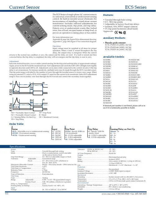
Application •Fine Chemicals•Petrochemical industry •Power stations•Environmental engineering •Measuring range:–Resistance insert (RTD):–200 to 600 °C (–328 to 1 112 °F)–Thermocouple (TC):–40 to 1 100 °C (–40 to 2 012 °F)•Static pressure range up to 75 bar dependent on the used process connection •Protection class: IP66/68Head transmitterAll Endress+Hauser transmitters are available with enhanced accuracy and reliability compared to directly wired sensors. Easy customizing by choosing one of the following outputs and communication protocols:•Analog output 4 to 20 mA •HART ®•PROFIBUS ® PA•FOUNDATION Fieldbus™Your benefits•For plug-in/screw-in with sliding compression fitting •High degree of flexibility thanks to modular design with standard terminal heads as per DIN EN 50446 and customer-specific immersion lengths•High degree of insert compatibility and design as per DIN 43772•Types of protection for use in hazardous locations:–Intrinsic Safety (Ex ia)–Flameproof (Ex d)–Non-sparking (Ex nA)Technical InformationOmnigrad S TR65, TC65Modular ThermometerTR65 with resistance insert (RTD)TC65 with thermocouple insert (TC)TI01031T/09/EN/01.1271161897Omnigrad S TR65, TC65Function and system designMeasuring principle Resistance thermometer (RTD)These resistance thermometers use a Pt100 temperature sensor according to IEC 60751. The temperaturesensor is a temperature-sensitive platinum resistor with a resistance of 100 W at 0 °C (32 °F) and a temperaturecoefficient a = 0.003851 °C-1.There are generally two different kinds of platinum resistance thermometers:•Wire wound (WW): Here, a double coil of fine, high-purity platinum wire is located in a ceramic support.This is then sealed top and bottom with a ceramic protective layer. Such resistance thermometers not onlyfacilitate very reproducible measurements but also offer good long-term stability of the resistance/temperature characteristic within temperature ranges up to 600 °C (1112 °F). This type of sensor is relativelylarge in size and it is comparatively sensitive to vibrations.•Thin film platinum resistance thermometers (TF): A very thin, ultrapure platinum layer, approx. 1 m mthick, is vaporized in a vacuum on a ceramic substrate and then structured photolithographically. Theplatinum conductor paths formed in this way create the measuring resistance. Additional covering andpassivation layers are applied and reliably protect the thin platinum layer from contamination and oxidation,even at high temperatures.The primary advantages of thin film temperature sensors over wire wound versions are their smaller sizes andbetter vibration resistance. A relatively low principle-based deviation of the resistance/temperaturecharacteristic from the standard characteristic of IEC 60751 can frequently be observed among TF sensors athigh temperatures. As a result, the tight limit values of tolerance category A as per IEC 60751 can only beobserved with TF sensors at temperatures up to approx. 300 °C (572 °F). For this reason, thin-film sensors aregenerally only used for temperature measurements in ranges below 400 °C (932 °F).Thermocouples (TC)Thermocouples are comparatively simple, robust temperature sensors which use the Seebeck effect fortemperature measurement: if two electrical conductors made of different materials are connected at a point, aweak electrical voltage can be measured between the two open conductor ends if the conductors are subjectedto a thermal gradient. This voltage is called thermoelectric voltage or electromotive force (emf.). Its magnitudedepends on the type of conducting materials and the temperature difference between the "measuring point"(the junction of the two conductors) and the "cold junction" (the open conductor ends). Accordingly,thermocouples primarily only measure differences in temperature. The absolute temperature at the measuringpoint can be determined from these if the associated temperature at the cold junction is known or is measuredseparately and compensated for. The material combinations and associated thermoelectric voltage/temperaturecharacteristics of the most common types of thermocouple are standardized in the IEC 60584 and ASTM E230/ANSI MC96.1 standards.2Endress+HauserOmnigrad S TR65, TC65Endress+Hauser 3AActive barrier RN221N - The RN221N (24 V DC, 30 mA) active barrier has a galvanically isolated output for supplying voltage to loop-powered transmitters. The universal power supply works with an input supply voltage of 20 to 250V DC/AC, 50/60 Hz, which means that it can be used in all international power grids. More information on this can be found in the Technical Information (see "Documentation").BRIA16 field display unit - The display unit records the analog measuring signal from the head transmitter and shows this on the display. The LC display shows the current measured value in digital form and as a bar graph indicating a limit value violation. The display unit is looped into the 4 to 20 mA circuit and gets the required energy from there.More information on this can be found in the Technical Information (see "Documentation").CMounted thermometer with head transmitter installed.Designå 2Thermometer design1Complete thermometer with terminal head and fixed thread 2Thermometer with sliding process connections 3Insert with terminal block mounted (example)4Insert with head transmitter mounted (example)MLInsertion lengthThermometers from the Omnigrad TR65 and TC65 series have a modular design. The terminal head is used as a connection module for the mechanical and electrical connection of the insert. The position of the actual thermometer sensor in the insert ensures that it is mechanically protected. The insert has flying leads, a ceramic connection socket or mounted temperature transmitter.Omnigrad S TR65, TC654Endress+HauserMeasuring range•RTD: –200 to 600 °C (–328 to 1 112 °F)•TC: –40 to 1 100 °C (–40 to 2 012 °F)Performance characteristicsOperating conditionsAmbient temperatureProcess pressureThe maximum process pressure depends on the used process connection. For an overview of the process connections which may be used, see chapter "Process connection" (®ä 13).Omnigrad S TR65, TC65Endress+Hauser 5Permitted flow velocity depending on the immersion lengthThe highest flow velocity tolerated by the thermometer diminishes with increasing immersion length exposed to the stream of the fluid. In addition it is dependent on the diameter of the thermometer tip, on the kind of measuring medium, on the process temperature and on the process pressure. The following figures exemplify the maximum permitted flow velocities in water and superheated steam at a process pressure of 1 MPa (10 bar).v (ft/s)L (in)v (m/s)0510152025303505010015020025030035040045050005101520253035050100150200250300350400450500v (m/s)L (mm)L (mm)AB2468101214161820L (in)2468101214161820153045607590105v (ft/s)0153045607590105 A0010867å 3Maximum flow velocityA Medium water at T = 50 °C (122 °F)B Medium superheated steam at T = 400 °C (752 °F)L Immersion length v Flow velocity-----Insert diameter 3 mm (0.12 in)- - -Insert diameter 6 mm (0.24 in)Shock and vibration resistance•RTD: 3G / 10 to 500 Hz according to IEC 60751•TC: 4G / 2 to 150 Hz according to IEC 60068-2-6Omnigrad S TR65, TC656Endress+HauserAccuracyRTD resistance thermometer as per IEC 607511)|t| = absolute value °CIn order to obtain the maximum tolerances in °F, the results in °C must be multiplied by a factor of 1.8.Permissible deviation limits of thermoelectric voltages from the standard characteristic for thermocouples as per IEC 60584 or ASTM E230/ANSI MC96.1:1)|t| = absolute value °C1)|t| = absolute value °COmnigrad S TR65, TC65Endress+Hauser 7Response timeCalculated at an ambient temperature of approx. 23 °C by immersing in running water (0.4 m/s flow rate,10 K excess temperature):Response time for insert without transmitter.Insulation resistance Insulation resistance ≥100 M W at ambient temperature.Insulation resistance between the terminals and the extension neck is measured with a voltage of 100 V DC.Self heatingRTD elements are passive resistances that are measured using an external current. This measurement current causes a self-heating effect in the RTD element itself which in turn creates an additional measurement error.In addition to the measurement current, the size of the measurement error is also affected by the temperature conductivity and flow velocity of the process. This self-heating error is negligible when an Endress+Hauser iTEMP ® temperature transmitter (very small measurement current) is connected.CalibrationEndress+Hauser provides comparison temperature calibration from –80 to +1 400 °C (–110 to +2 552 °F)based on the International Temperature Scale (ITS90). Calibrations are traceable to national and international standards. The calibration certificate is referenced to the serial number of the thermometer. Only the insert is calibrated.Omnigrad S TR65, TC65Material Process connection, insertThe temperatures for continuous operation specified in the following table are only intended as reference valuesfor use of the various materials in air and without any significant compressive load. The maximum operationtemperatures are reduced considerably in some cases where abnormal conditions such as high mechanical loadoccur or in aggressive media.1)Can be used to a limited extent up to 800 °C (1472 °F) for low compressive loads and in non-corrosive media. Pleasecontact your Endress+Hauser sales team for further information.8Endress+HauserOmnigrad S TR65, TC65Endress+Hauser9ComponentsFamily of temperature transmittersThermometers fitted with iTEMP ® transmitters are an installation-ready complete solution to improvetemperature measurement by significantly increasing accuracy and reliability, when compared to direct wired sensors, as well as reducing both wiring and maintenance costs.PC-programmable TMT180 and TMT181 head transmittersThey offer a high degree of flexibility, thereby supporting universal application with low inventory storage. The iTEMP ® transmitters can be configured quickly and easily at a PC. Endress+Hauser offers the ReadWin ® 2000configuration software for this purpose. This software can be downloaded free of charge at . More information can be found in the Technical Information.HART ® TMT182 head transmitterHART ® communication is all about easy, reliable data access. It means that additional information on the measurement point can be obtained more cost-effectively. iTEMP ® transmitters integrate seamlessly into your existing control system and provide trouble-free access to a wide range of diagnostic information.Configuration is done using a hand-held device (Field Xpert SFX100 or DXR375) or a PC with configuration program (FieldCare, ReadWin ® 2000). AMS or PDB can also be used for configuration purposes. More information can be found in the Technical Information.HART ®-programmable iTEMP ® head transmitter TMT82The iTEMP ® TMT82 is a loop-powered device with two measurement inputs and one analog output. The device not only transfers converted signals from resistance thermometers and thermocouples, it also transfers resistance and voltage signals using HART ® communication. It can be installed as an intrinsically safe apparatus in hazardous areas, zone 1 and is used for instrumentation purposes in the terminal head, flat face as per DIN EN 50446. Swift and easy operation, visualization and maintenance by means of a PC using configuration software such as FieldCare, Simatic PDM oder AMS. Benefits are: dual sensor input, highest reliability, accuracy and long-term stability in critical processes, mathematic functions, thermometer drift monitoring, sensor back-up functionality, sensor diagnosis functions and sensor-transmitter matching using Callendar-Van Dusen coefficients. More information can be found in the Technical Information.PROFIBUS ® PA iTEMP ® head transmitter TMT84Universally programmable head transmitter with PROFIBUS ® PA communication. Conversion of various input signals into digital output signals. High accuracy over the complete ambient temperature range. Swift and easy operation, visualization and maintenance using a PC directly from the control panel, e.g. using operating software such as FieldCare, Simatic PDM or AMS. Benefits are: dual sensor input, highest reliability in harsh industrial environments, mathematic functions, thermometer drift monitoring, sensor back-up functionality,sensor diagnosis functions and sensor-transmitter matching using Callendar-Van Dusen coefficients. More information can be found in the Technical Information.FOUNDATION Fieldbus™ iTEMP ® head transmitter TMT85Universally programmable head transmitter with FOUNDATION Fieldbus™ communication. Conversion of various input signals into digital output signals. High accuracy over the complete ambient temperature range.Swift and easy operation, visualization and maintenance using a PC directly from the control panel, e.g. using operating software such as ControlCare from Endress+Hauser or NI Configurator from National Instruments.Benefits are: dual sensor input, highest reliability in harsh industrial environments, mathematic functions,Omnigrad S TR65, TC65thermometer drift monitoring, sensor back-up functionality, sensor diagnosis functions and sensor-transmittermatching using Callendar-Van Dusen coefficients. More information can be found in the Technical Information.Terminal heads All terminal heads have an internal shape and size in accordance with DIN EN 50446, flat face and athermometer connection of M24x1.5, G1/2" or 1/2" NPT thread. All dimensions in mm (in). The cable glandsin the diagrams correspond to M20x1.5 connections. Specifications without head transmitter installed. Forambient temperatures with head transmitter installed, see "Operating conditions" section.TA30H10Endress+HauserOmnigrad S TR65, TC65Endress+Hauser11Omnigrad S TR65, TC65 Design All dimensions in mm (in).å 4Dimensions of the Omnigrad S TR65 and TC651Complete thermometer with terminal head and fixed thread2Thermometer with sliding process connections3Insert with terminal block mounted4Insert with head transmitter mounted5Insert with flying leadsTL Screw-in lengthML Insertion lengthIL Total length of insertÆID Insert diameterWeight0.5 to 2.5 kg (1 to 5.5 lbs) for standard options.12Endress+HauserOmnigrad S TR65, TC65Process connection The process connection is the means of connecting the thermometer to the process. The following processconnestions are available:å 5Process connectionsSpare parts The following compression fittings are available as spare parts:Endress+Hauser13Omnigrad S TR65, TC65WiringWiring diagrams for RTD Type of sensor connection14Endress+HauserOmnigrad S TR65, TC65Wiring diagrams for TC Thermocouple wire colorsEndress+Hauser15Omnigrad S TR65, TC6516Endress+HauserInstallation conditionsOrientationNo restrictions.Installation instructionsparameters and the process to be measured must be taken into account (e.g. flow velocity, process pressure).•Installation possibilities: Pipes, tanks or other plant components•Recommended minimum immersion length: 80 to 100 mm (3.15 to 3.94 in)The immersion length should correspond to at least 8 times of the thermowell diameter. Example:Thermowell diameter 12 mm (0.47 in) x 8 = 96 mm (3.8 in). A standard immersion length of 120 mm (4.72 in) is recommended.•ATEX certification: Always take note of the installation regulations!Certificates and approvalsCE MarkThe device meets the legal requirements of the EC directives if applicable. Endress+Hauser confirms that the device has been successfully tested by applying the CE mark.Hazardous area approvalsFor further details on the available Ex versions (ATEX, CSA, FM etc.), please contact your nearest Endress +Hauser sales organization. All relevant data for hazardous areas can be found in separate Ex documentation.Other standards and guidelines•EN 60079: ATEX certification for hazardous areas •IEC 60529: Degree of protection of housing (IP code)•IEC 61010-1: Protection Measures for Electrical Equipment for Measurement, Control, Regulation and Laboratory Procedures.•IEC 60751: Industrial platinum resistance thermometers •IEC 60584 and ASTM E230/ANSI MC96.1: ThermocouplesOmnigrad S TR65, TC65Endress+Hauser 17•EN 50014/18: Electrical equipment for hazardous areas - General regulations/Flameproof enclosure "d"•DIN EN 50446: Terminal heads•IEC 61326-1: Electromagnetic compatibility (EMC requirements)PED approvalThe thermometer complies with paragraph 3.3 of the Pressure Equipment Directive 97/23/CE and is not marked separately.Test report and calibrationThe "Factory calibration" is carried out according to an internal procedure in a laboratory of Endress+Hauser accredited by the European Accreditation Organization (EA) to ISO/IEC 17025. A calibration which isperformed according to EA guidelines (SIT or DKD calibration) may be requested separately. The calibration is performed on the replaceable insert of the thermometer. In the case of thermometers without a replaceable insert, the entire thermometer - from the process connection to the tip of the thermometer - is calibrated.Ordering informationDetailed ordering information is available from the following sources:•In the Product Configurator on the Endress+Hauser website: ® Select country ®Instruments ® Select device ® Product page function: Configure this product •From your Endress+Hauser Sales Center:/worldwideProduct Configurator - the tool for individual product configuration •Up-to-the-minute configuration data•Depending on the device: Direct input of measuring point-specific information such as measuring range or operating language•Automatic verification of exclusion criteria•Automatic creation of the order code and its breakdown in PDF or Excel output format •Ability to order directly in the Endress+Hauser Online ShopDocumentationTechnical information:•Temperature head transmitter:–iTEMP ® TMT180, PC-programmable, single-channel, Pt100 (TI088R/09/en)–iTEMP ® PCP TMT181, PC programmable, single-channel, RTD, TC, Ω, mV (TI00070R/09/en)–iTEMP ® HART ® TMT182, single-channel, RTD, TC, Ω, mV (TI078R/09/en)–iTEMP ® HART ® TMT82, two-channel, RTD, TC, Ω, mV (TI01010T/09/en)–iTEMP ® PROFIBUS ® PA TMT84, two-channel, RTD, TC, Ω, mV (TI138R/09/en)–iTEMP ® FOUNDATION Fieldbus TM TMT85, two-channel, RTD, TC, Ω, mV (TI134R/09/en)•Application example:–RN221N active barrier, for supplying loop-powered 2-wire transmitters (TI073R/09/en)–RIA16 field display, loop-powered (TI00144R/09/en)Process connection:Compression fitting Omnigrad TA50 (TI091t/02/en)Hazardous area (ATEX) supplementary documentation:•RTD/TC Thermometer Omnigrad TRxx, TCxx, TxCxxx, ATEX II 1GD or II 1/2GD Ex ia IIC T6...T1(XA072R/09/a3)•RTD/TC Thermometer Omnigrad S TR/TC6x, ATEX II1/2, 2GD or II2G (XA014T/02/a3)•RTD/TC Thermometer Omnigrad S TR/TC6x, ATEX II 1/2 or 2G; II 1/2 or 2D; II 2G (XA00084R/09/a3)Instruments International Endress+Hauser Instruments International AG Kaegenstrasse 24153 ReinachSwitzerlandTel.+41 61 715 81 00Fax+41 61 715 25 00***************.comTI01031T/09/EN/01.12 71161897。
压⼒变送器使⽤说明书安装○普通型及⼩巧型变送器的安装①若压⼒系统有瞬间过压,该变送器过载范围满⾜系统要求,并配置缓冲阀;②测量介质应与变送器的结构材料相兼容;③测量介质不能堵塞变送器的引压孔;④禁⽌随意拆卸、碰撞变送器及强⾏绞拧导线,严禁⽤异物捅引压孔;⑤根据产品连续类型,查对现场接⼝是否与产品⼀致。
若为螺纹接⼝,应缓速拧紧,注意密封,不能把转矩直接加到变送器壳体上,只能加在压⼒接⼝的六⾓上。
○投⼊式变送器的安装●注意事项①安装地点的液体可能产⽣的静压⼒不能超过变送器的量程;②测量介质应与变送器的结构材料相兼容;③测量介质不能堵塞变送器的进液孔;④安装时要缓速放⼊或提出,严禁⽤强⼒拉扯电缆或⽤⾦属等硬物捅压膜⽚。
●安装⽅法变送器的安装⽅向为垂直向下,在动⽔中使⽤时,应注意使变送器压⾯与⽔流⽅向平⾏。
1在静⽔中安装①在⽔池中的安装⽅法:为防⽌⽔泵打⽔时的冲击抖动变送器或损坏变送器或损坏变送器,应将变送器原理液体出⼊⼝安装。
(如图a所⽰)②在深井中的安装⽅法:⼀般⽤插钢管的⽅法,要求钢管不能打弯,内劲必须⼤于35mm,易上下提动变动器,在钢管的不同⾼度上若⼲⼩孔,以便⽔通畅进⼊管内,必要时,可在变送器上缠烧钢丝,⽤钢丝上下提动,以免拉断电缆线。
(如图b所⽰)2在动⽔中安装在动⽔中安装时需加静⽔装置①⽅法之⼀:在⽔道中插⼊钢管,要求钢管壁稍厚⼀些,并在其上下不同⾼度若⼲个⼩孔,以阻尼⽔波和消除动⽔压⼒的影响。
(如图c所⽰)②⽅法之⼆:若为清⽔域的沙⽯⽔床,以浅埋为好。
(如图d所⽰)③⽅法之三:这种⽅法即能消除⽔流压⼒和波浪的影响⼜能起到过滤浊⽔泥沙的作⽤(如图e所⽰)○普通型及投⼊式变送器接线信号(电源)端⼦设置在电⽓盒的⼀个独⽴腔室内。
接线前,先拧下表盖,把信号(电源)线从穿线孔穿⼊,把线接在+、-端⼦及地上,拧紧表盖和穿线孔螺栓。
信号线不要与其它电源线⼀起穿⾦属管或放在同⼀线槽中,也不要再强电设备附近通过。


TPGAA - PRESSURE TRANSMITTERApplicAtionsAscon tecnologic s.r.l.viale Indipendenza, 56 - 27029 Vigevano (PV) Italytel +39 0381 69 871 - fax +39 0381 69 87 30************************PRESSURE TRANSMITTERS FOR OEM CUSTOMERS• COMPRESSOR• BUILDING WATER SUPPLY • HYDRAULIC CONTROL • AIR-CONDITIONING UNIT • AUTO ENGINE• AUTOMATIC DETECTION SYSTEM • HYDRAULIC UNIT• REFRIGERATION EQUIPMENTTPGAA series pressure transmitter is a mass production, cost effective for OEM, high quality and high reliability product applied to both civil and industrial.Widely used to measure on-site pressure of compressor, auto and air-condition, etc., this product adopts 316L stainless steel structure, piezore-sistive sensor chip imported from Germany.Calibration and compensation are done with digital tecnique.Standard current and voltage output.The mass production adopts military technique, to optimize the manufa-cuting process.CE certification.Features:- Accuracy: 1%FS (±0.5% FS);- High stability, high reliability;- Piezoresistive core from Germany;- Digital calibration;- Multiple pressures;- CE certification;- Conform with RoHs standard.Ascon tecnologic FranceBP 76 · 77202 - Marne La Vallee Cedex 1tel +33 1 64 30 62 62 · fax +33 1 64 30 84 98***********************www.ascontecnologic.frAscon polska sp. z o.o.KOCHCICE ul. Kochanowicka 4342-713 Kochanowicetel +48 34 35 33 619 · fax +48 34 35 33 884*************www.ascon.plAscon tecnologic - north America1111 Brook Park Road Cleveland, OH 44109tel. +1 216 485 8350 ext. 229********************/encoelmatic ltdaRua Clélia 1810 - LapaSao Paulo · SP - CEP 05042-001- Brazil tel. +55 11 2066-3211 · fax +55 11 3046-8601*************.br.brcoelmatic sApi sA de cVDr. Pedro Noriega #1099 - Col Terminal Monterrey, Nuevo León - CEP 64570tel. +52 81 8104 1012******************.mx www. .mxPrinted in September 2019. This publication belongs exclusively to Ascon Tecnologic S.r.l. and may not be reproduced unless with expressed authorisation. Ascon Tecnologic S.r.l. reserves the right to make modifications without warningDistributors and assistance Worldwide. contatct Ascon tecnologic for more info.SPECIFICATIONS(@ 20°C)DIMENSIONS[mm]。
Senstronics系列压力变送器使用说明书Senstronics系列压力变送器使用说明书感谢您使用senstronics公司生产的压力变送器,产品使用前请仔细阅读使用说明书便帮助您正确了解、使用本产品。
1 开启产品包装后,请检查产品外观是否完好,核定产品是否与所订产品相一致。
2 严格按产品接线示意图连接,并在产品允许激励电压下工作,切勿过电压使用。
3 严禁产品长时间过压力使用,产品出现异常时,请停机检查。
4 产品长期使用后,测试介质可能会堵塞引压孔,清洗产品引压孔时,可使用能溶解物之液体多次清洗。
禁止使用坚硬器具深入引压孔,以免损坏感压膜片。
5 产品无客户自行维修部件,出现故障请与我公司联系。
6 未涉及之处,请查阅我公司相关资料或来电咨询。
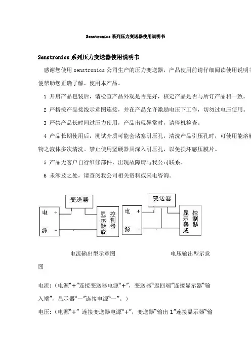
电流输出型示意图电压输出型示意图电流:(电源“+”连接变送器电源“+”,变送器“返回端”连接显示器“输入端”,显示器“—”连接电源“—”。
)电压:(电源“+” 连接变送器电源“+”,变送器“输出1”连接显示器“输入端”,显示器“—”和变送器“—”、电源“—”连接。
)附件二:压力元件和封装型产品数据表温度=20℃, 电源供电=10V的数据值(除非另有说明)电参数电参数最小典型最大单位说明()电源(Vs) - 10 20 V输入阻抗(Vs 到Vg) 2925 3400 4070 Ω(包括串联补偿电阻)输出阻抗(Vh 到Vl) 2800 3200 3800 Ω零位(Vdiff= Vh - V1) -1 0 1 mV/Vs (正比于电源电压Vs)DC绝缘是指应变电桥对基体 100* 500** V (*100% 敏感元件测试>40MΩ**100%批生产试验>200MΩ)热参数:参数最小最大单位说明()工作温度范围-40 150 ℃零位温度误差-0.25 0.25 %f.s. 每100℃满量程温度误差-0.25 0.25 %f.s. 每100℃温度条件下迟滞<±0.05 %f.s.温度零位漂移<±0.1 %f.s. (在+125℃温度下90小时)参数最小最大单位说明()量程、线性度、迟滞和重复性对于单个敏感元件和封装组件.机械稳定性<±0.15 %f.s. (在1Χ106f.s.压力循环试验后)静态压力 x2.0* 额定压力范围(零位漂移<±0.1%f.s)动态压力 x1.25* 额定压力范围(零位漂移<±0.1%f.s)爆破压力> x10 额定压力范围(最大压力试验为2750bar)频率响应(谐振)> 10kHZ*任何使用压力一定要小于耐压规定,以防止大的零位漂移.温度输出(Vc相对于Vg):参数最小最大单位说明()Vc 零位400 450 mV/Vs (正比于电源电压Vs)Vc 灵敏度4575 4650 ppm /℃(来自内部量值)压力敏感元件及封装组件非线性是指在全压力范围内输出与理论直线的最大偏差(不包括迟滞),满量程输出是指每伏的毫伏输出,它与电源电压成比例,误差是以±3σ计算。
凯诺10t重量传感器说明书1. 产品概述凯诺10t重量传感器是一种用于测量物体质量的专业传感器。
它采用最新的传感技术,具有高精度、高稳定性和高可靠性的特点。
该传感器适用于工业生产、仓储物流、运输等领域,广泛应用于货物称重、过磅系统等场景。
2. 技术参数•额定负荷:10t•额定输出:2.0±0.1mV/V•线性度:≤±0.02%F.S.•零点温漂:≤±0.02%F.S./℃•输出温漂:≤±0.02%F.S./℃•工作温度范围:-30℃~+70℃•安全过载:150%F.S.•最大过载:200%F.S.3. 结构及工作原理凯诺10t重量传感器采用了双剪切梁结构设计,具有良好的抗侧向力能力和抗振动能力。
其工作原理基于应变片效应,通过测量应变片的电阻变化来间接测量物体的质量。
传感器的内部结构精密稳定,能够提供可靠的测量结果。
4. 安装与使用4.1 安装•将传感器固定在称重平台上,确保其与称重平台紧密连接。
•使用合适的螺栓将传感器固定在称重平台上,并确保螺栓牢固可靠。
•连接传感器的电缆线到相应的显示设备或数据采集系统。
4.2 使用•在使用前,请先检查传感器的连接是否牢固,并确保电源供应正常。
•将待测物体放置在称重平台上,并等待一段时间使其稳定。
•启动显示设备或数据采集系统,读取并记录测量结果。
5. 注意事项•在安装和使用过程中,请避免过大的冲击和震动,以免影响传感器的性能和寿命。
•不要将传感器暴露在高温、潮湿或腐蚀性环境中,以免损坏传感器。
•避免超过安全过载和最大过载范围进行测量,以免对传感器造成损坏。
•定期检查和校准传感器,确保其测量结果的准确性和可靠性。
•当传感器长时间不使用时,建议将其存放在干燥、温度适宜的环境中。
6. 常见问题解答6.1 如何校准传感器?传感器的校准可以通过使用已知质量的物体进行比对来完成。
具体操作步骤请参考产品附带的校准指南。
6.2 为什么测量结果不稳定?测量结果不稳定可能是由于以下原因导致: - 安装不牢固:请检查传感器是否与称重平台紧密连接。
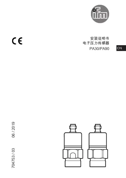
安装说明书电子压力传感器PA30/PA90 CN704753 / 03 06 / 20191 使用的符号►说明重要说明如不遵守,可能导致故障或干扰。
信息 补充说明。
2 安全说明• 所述设备为集成至系统的子组件。
-系统制造商需为系统的安全负责。
-系统制造商根据运营商和系统用户提供的法规和规范要求来实施风险评估和存档。
该存档必须包含针对运营商和用户(如适用,还要包含系统制造商授权的维修人员)的所有必要信息和安全说明。
• 设定产品前请阅读本文档,并在产品整个使用周期内妥善保管本文档。
• 产品必须适合相应的应用和环境条件,且不受任何限制。
• 仅将产品用于指定用途(→ 功能和特性)。
• 仅将产品用于允许的介质(→ 技术资料)。
• 如果未遵照操作说明或技术资料,则可能导致人身伤害和/或财产损失。
• 对于操作员擅自改装产品或错误使用导致的任何后果,制造商概不承担任何责任。
• 必须由设备操作员授权的合格人员执行设备的安装、电气连接、设定、操作及维护工作。
• 防止产品和电缆损坏。
3 功能和特性该压力传感器可检测系统压力,并将其转换为模拟输出信号。
• 4 ... 20 mA (PA30xx) / 0 ... 10 V (PA90xx)23CN3.1 应用范围•压力类型: 相对压力请采取适当措施,避免静态和动态过压超过指示的过载压力。
切勿超过指示的爆破压力。
即使仅在短时间内超过爆破压力,也可能损坏设备。
注意: 谨防人身伤害危险!仅在与制造商 IFM 联系后,方用于压力高于 25 bar 的气体中。
250 bar 和 400 bar 版本随附减压机构和集成阻尼装置,可在超过爆破压力而发生爆破时,避免造成任何人身伤害。
4安装安装和卸除传感器前,请确保系统未承受任何压力。
►将设备插入 G¼ 过程连接中。
►充分紧固。
若阻尼装置必须移除,请确保其未受损伤。
请勿使用受损的阻尼装置。
如果您有任何疑问,请与 IFM 电子的销售专员联系。
压力传感器型安全操作及保养规程引言压力传感器是一种常用的测量仪器,其工作环境多数较为复杂,因此使用过程中需要遵循一些操作规程和保养方法,确保设备的安全性、可靠性以及寿命。
本文将介绍压力传感器型安全操作及保养规程,欢迎参考使用。
安全操作1. 基础操作•在进行任何操作之前,必须确保检查设备是否启动、连接稳定,并已经完成系统准备工作。
•针对不同应用环境和压力传感器型号,必须了解和掌握设备的使用说明和注意事项。
•在进行任何操作之前,必须切断设备的电源,并采取相关措施确保效果,以防止意外电击和设备意外启动。
2. 连接与拆卸•进行设备连接和拆卸操作时,必须在安全的场所进行,确保场地干燥、清洁且平稳有序。
•切勿使用不符合压力传感器类型和规格的连接器件。
•操作前确保有正确的连接或拆卸设备的工具,以避免锯齿、磨损或者其他损伤。
3. 压力测量•进行压力测量前,必须根据压力范围选择相应的测量仪器,并且进行相关的检查。
•在进行测量过程中,必须采用适当的测量点,并检查不同像位的压力数据,并保持数据的准确性和稳定性。
•当测量过程中出现异常,及时停止并查找原因,并按照指引进行处理。
4. 安全保护•避免设备各部分压力过大,使用前应先了解设备的基本压力范围,以正确使用并设置压力保护装置。
•严禁超量使用,超量使用容易造成设备负荷过大,压力传感器容易受到损伤。
•严禁超频使用,超频使用会导致设备温度过高,导致损坏设备。
保养规程1. 保养前检查•每次进行保养操作前,必须对设备进行全面的检查,确保设备完好无损。
•在保养前必须将设备的电源切断,并检查所有连接是否正常,以避免意外开机和电击风险。
2. 保养过程•保养时建议采用原装的压力传感器配件,并按照使用说明进行处理。
•必须避免使用任何化学物质或油脂,因为这些可能会导致设备损坏和安全隐患。
•保养时应进行清理、刷洗、防锈和润滑工作,以确保设备运行的稳定性和可靠性。
3. 保养后•保养后必须进行全面的检查以确保设备处于正常工作状态。
EC 系列不锈钢压力传感器是针对环境恶劣的工业环境开发产品。
EC 系列传感器结构坚固,内部信号放大,而且价格低廉,内部没有O 型圈等弹性密封材料,有不锈钢膜保护内部电路,只有不锈钢部分与被测介质接触,是工业场合理想的压力传感器。
EC 有2种输出标准;0.5-4.5 Vdc 比例线性输出;4-20mA 输出。
压力量程最高可达500Bar 。
典型应用液压气动设备 空气压缩机 能源管理系统 智能制冷、压缩设备过程控制发动机监控系统特点:●电流电压输出,压力量程宽● 室外用接头● 内部没有弹性密封结构,有不锈钢隔离膜● 低电压供电● 反极性保护● 输出符合工业标准● IP65密封等级● 超过CE 重工业标准EMC 优点:● 应用广泛,优秀的OEM 产品● 可靠性高,使用灵活● 介质兼容性很好,对内部电子器件有完整的保护● 可用于ORV 和船只● 使用简单● 减少OEM 的配套成本● 不会被反向接线所损坏● 能工作于恶劣环境选型表:型号量程PSI01502505010020030050001K 02K03K05K07K Bar 001002004007010025020035050100200350500单位P=PSIB=BAR 输出C=0.5-4.5VDC G=4-20mA 端子P=Packard H=Hirschmann 压力接口1=1/8NPT 6=G1/4BSP 压力类型G=Gage(PSIG)S=Sealed(PSIS)注:并不是每种组合都可选EC100P S 1P G推荐型号EC010BS2PGEC025BS2PGEC350BS2PG 量程10bar 25bar 350bar安装尺寸:引脚1234电压输出型—输出公共线电源 正电流输出型——电源负,且电流信号返回电源正安装尺寸:引脚ABC 电压输出型电源 正输出公共线电流输出型 电源 正 电源负,且电流信号返回 —技术规格物理性能过压爆破压力介质材料重量电气性能零输出满量程输出供电电压反极性保护绝缘电阻环境性能冲击EMI/RFI电气连接精度整体误差操作、储藏温度补偿温度015,025,050,100,200,300,500,1k,2k,3k,5k,7k psig*1,2.5,4,6,10,16,25,40,60,100,160,250,350,500 bars<500psi,2倍满量程<500psi,10倍满量程300系列不锈钢,黄铜,内部密封材料,硅75克≥500psi, 1.5倍满量程≥500psi,10倍满量程(30k psi 最大值) 比例电压输出0.5Vdc 4Vdc(0.5~4.5Vdc)5Vdc ±250mV(测量条件:7.0max) 电流输出4.0mA 16mA(4-20mA)10-40 Vdc (25-100˚C,超过35 Vdc线性度降低)有@250Vdc 50峰值(5ms )超过CE 重工业标准Packard # 12065287连接器,需单独订货, Hirschmann 插头可选,不需单独订购满量程+/-1%,包括:非线性,迟滞,非重复性;不包括温度漂移满量程+/-4%,满量程漂移,零点漂移,非线性,迟滞,非重复性-40~105˚C -1~82˚C 量程1000M ΩHONEYWELL 压力传感器公司由传感器销售部、仪表销售部、工程部和总务部四个部组成。
n o i t a c i f i c e p S g n i r e e n i g n EMettler-Toledo Thornton, Inc.36 Middlesex Turnpike,Bedford, MA 01730 USATel. +1-781-301-8600Fax +1-781-301-8701Toll Free +1-800-510-PURE********************Customer/Technical ServiceToll-Free +1-800-642-4418Fax +1-781-271-0214Subject to technical changes© Mettler-Toledo Thornton, Inc.EN0106 Rev.A 2//thornton For more information Four 0/4-20 mA output signals shall be assignable to any measurements. Output scaling shall be selectable as linear, bi-linear, logarithmic or auto-range (to provide high resolution at the low end of the range yet keep high measurements on-scale during upset, startup or calibration). A USB port shall also be provided for data acquisi-tion and remote configuration.The instrument shall be ISO9001 factory calibrated to NIST-traceable standards and be provided with a certificate of calibration. An accessory NIST-traceable resistance calibration module, interchangeable with conductivity sen-sors, shall be available to permit full field calibration of conductivity/resistivity and temperature measurements,including leadwire effects. Conductivity sensor cell constants shall be individually ISO9001 factory calibrated to ASTM traceable standards, with final verification in 18+ Megohm-cm pure water for 0.1 cm-1 sensors. They shall be provided with certificates of calibration.The indicating transmitter and sensor(s) shall be Mettler-Toledo Thornton model M300 Instrument, with compati-ble conductivity, pH, ORP, dissolved oxygen and/or dissolved ozone sensors, as specified.E n g i n e e r i n g S p e c i f i c a t i o n s。
TCD210040AAL 3.7 mm薄型光电传感器BTF Series产品手册ᜢᜫ- W 13 × H 19 × L 3.7 mm (对射型)- W 13 × H 24 × L 3.7 mm (漫反射型, BGS 反射型)• 可检测微小物体- 对射性 (BTF1M): Ø 2 mm- 漫反射型 (BTF30): Ø 0.2 mm (检测距离 10 mm) - BGS 反射型 (BTF15): Ø 0.2 mm (检测距离 10 mm)• 采用 B GS 方式,免受背景物体颜色, 材质引起的误差,实现稳定的检测(BGS 反射型)• 最大检测距离 1 m (对射型)• 动作指示灯(红色), 稳定指示灯(绿色), 方便确认动作状态• 采用不锈钢 (SUS304) 安装支架• IP67 防护等级 (I EC 规格)请务必遵守使用说明书,手册,奥托尼克斯网页等的注意事项。
本文中所记载产品的外形及规格等因产品性能改进或资料改善而变更或停产时,恕不另行通知。
内容。
特殊条件下可能会发生意外或危险。
01. 02. 禁止在易燃易爆腐蚀性气体,潮湿, 阳光直射,热辐射, 振动, 冲击, 盐性的环境下使用。
03. 请勿任意改造产品。
04. 通电状态下请勿进行接线及检修作业。
05. 用于对人身及财产上影响大的机器(如: 核能控制, 医疗器械, 船舶, 车辆, 铁路, 航空, 易燃装置,防灾/防盗装置等)时,请务必加装双重安全保护装置。
否则可能会引起人身伤亡,财产损失及火灾。
否则有爆炸或火灾危险。
接线时,请确认接线图后进行连接。
否则有火灾危险。
否则有火灾危险。
否则有火灾危险。
警告 如违反此项,可能导致严重伤害或伤亡。
01. 请在额定规格范围内使用。
02. 清洁时请勿用水或有机溶剂,应用干毛巾擦拭。
否则有火灾及产品故障的危险。
否则有火灾危险。
注意 如违反此项,可能导致轻度伤害或产品损坏。