YW.YWB.YWZ5.YWZE系列电力液压块式制动器(HW)
- 格式:pdf
- 大小:4.77 MB
- 文档页数:14
YWZ5电力液压块式制动器YWZ5-400/80YWZ5-400/80 电力液压制动器 YWZ5电力液压推杆制动器 YWZ5制动器 YWZ5液压制动器广泛用于起重、冶金、矿山、港口、码头、建筑等机械驱动装置的减速和停车制动。
其安装尺寸和制动力矩参数符合JB/T6046-2006标准。
匹配Ed系列推动器性能安全可靠、制动平稳、动作频率高、制动力矩可调。
主要摆动铰点设自润滑轴承,传动效率高、寿命长,在使用过程中始终保持两侧瓦块退距均等,避免因退距不均使一侧制动衬垫浮帖制动轮的现象。
制动弹簧布置在弹簧管内,并在一侧设有制动力矩标尺,调整方便,直观。
可通过增设附加装置实现某些附加功能:手动释放装置释放(开闸)或闭合(闭闸)限位开关,可实现制动器是否正常释放或闭合的信号显示或连锁保护。
采用带下降延时阀的推动器推动,可实现制动器的延时闭合。
使用条件和规程:环境温度: -25℃~+45℃。
空气相对湿度:≤90%海拔高度:符合GB755-2000标准。
电源:三相交流50Hz·380V. (根据用户要求也生产用于要求可提供60Hz或不同电压的产品。
适应的工作制:连续(S1)和断续(S3-60%)工作制。
一、概述YWZ 、YWZ2、YWZ3、YWZ4、YWZ5等系列液压块式制动器主要用于起重、运输、冶金、矿山、港口、建筑机械驱动装置的机械制动,具有制动平稳,安全可靠、维修方便、耗电少、寿命长、无噪音等优点。
①WYZ 系列操作次数每小时可达720次。
符合JB/ZQ4388-86标准; ②WYZ2系列操作每小时可达1200次,符合JB/ZQ4388-86标准; ③YWZ3系列操作每小时可达720次,符合GB6333-86标准; ④YWZ4系列操作每小时可达1200次,符合JB/ZQ4388-86标准; ⑤YW Z5系列操作每小时可达1200次,符合GB6333-86标准;二、使用条件1、环境温度-20℃~+50%(低于推动器改为YH-10航空液压油)2、空气相对湿度不大于90%3、一般用于三相交流电源,50HZ,380V;4、海高度符合GB755-87标准;5、在无爆炸危险,且介质中无足以腐蚀金属和破坏绝缘的气体及放电尘埃中;6、YZW、YZW3使用YTI系列推动器,一般适用于垂直工作,倾斜度不超过±去15°三、产品型号及意义四、外形尺寸图五、YWZ5技术数据、外形尺寸表(毫米)BED-80/6隔爆型电力液压推动器BED-80/12隔爆型电力液压推动器品牌:虹发产地:河南价格:1000人民币/台规格:BED-80/6,BED-80/12简要说明:BED系列电力液压推动器主要用作YWZ4,YWZ5,YWZ8,YWZ9,YWZP系列电力液压块式制动器的操作元件,广泛适用于起重运输,冶金,矿山,港口,建筑等行业。
Cubic Electrical Hydraulic Brake YWZ SeriesUsers’Manual(For adjustment and maintenance)brake Co. Ltd. of CityAddress:Tel:Fax:Post Code:Website:E-mail:1. Essentials:Cubic Electrical Hydraulic Brake Series YWZ are mainly used in machines of such uses as craning ,transportation ,metallurgy, mining,porting, constructionand so on. They all accord with the JB/ZQ4388-97 standard.2. Working condifions:2.1 Temperature:-25℃-- +45℃(to see more information in the technical manual of YT1 promoter)2.2 No fire-catching,explosive or corrosive gas in the surrounding erwiroment.Relative air dampness not exceeding 90%.2.3 Power voltage to see the dataplate on promoter.2.4 The working altitude should conform to the standard of GB755-2000.3.Structure and fundamental theories:The Brake consist of a brake frame and a matching YT1 electrical hydraulic promoter when power is on ,the promoter works.Its stem rises quickly and loose the brake by a lever arm .When power off, the promoter’s stem falls quickly because of the push of the return spring and closes the brake by the lever arm .Note: structure may be differentaccording to different type and size(pi cture 1) picture of the structure1.screw bolt screw nut2.frame for installing brake tile3.brake tile4.brake arm5. screw bolt6. screw nut7. screw nut8. screw nut9.pull rod 10. screw nut 11.promoter 12.base4.type and data ( I )5.installation and adjustment5.1 check before installation :● check on the brake to see whether damage or less of parts happened● check and clean oil stains or other dirt on the surface of brakewheel if any5.2 installation of the brake :Please refer to picture I and follon the instructions here :●vertical installation : loose screw nuts number 6.7.8.10 tam thescrew stem 9 take off the brake arm ,and put the brake coat on the brake wheel;●horizontal installation : when brake wheel has been fixed on othermachines , loose screw nuts 6.7.8 and 10 then turn screw stem number9 and add on screw stems 5 and 9 ,put the brake arm on the brakewheel from a side .●After brake has been fixed on the base ,loosely drive the screwbolt on ,turn pull-rod 9.The screw nut in the frame for installing brake tile 2 should be at a proper position to get brake tiles and brake wheel tightly together . If there is still gap between them , continue turning pull rod 9 . Only when the best distance is reached can we stop turning the pull rod 9 and screw the nut tight .●Oil the promoter referring to it’s installations :5.3 Adjustment of the brake :● Adjustment of the promoter when working :First release foyce of the spring to the rising height (H1) of the promoter’s push rod conform to the statistics in table (一). With the wear and tear of the brake liner , working distance gets bigger and bigger , and H1 gets smaller and smaller when the numerial value of H1 gets to the smallest according to table II , ve-adjustment is needed according to the method above , otherwise the brake will become useless .●The adjustment of lever arm :Loosen nut 6, hold the sauare end of the screw-stem 5, drive nut 7, making the spring length conforms to the reference data on the data plate . When all is done , make screw nuts 6 and 7 tight .●The adjustment of returning the distance of the brake scotch : when thebrake tile is opened , adjust bolt 1 , make both sides return the distance and keep unanimity , If this serial brake is equipped with the equal retreat device , by which both sides retreat automatically equal when the brake is turned on , necdn’t adjust .●The nut 2 of the regular brake scotch (see the fig) should be fixed inconformity with elasticity to make the brake scotch can be up to the location with making driving wheel .6. Inspection and trying out before the brake is operated :6.1 Checking before running : The brake should be checked in an all-roundway before running , check whether every adjustment is correct , whether the locknut of every part is locked , impeller wiring is correct .6.2 Test run : Through check , all after being normal , brake should be testedfor several times at host engine , apply the brake liner carry on certain brake- in , in order to make them run well .7. How to use and maintain it :7.1 Check the brake regularly .7.2 Keep in mind the following points when checking .●To see whether any wear and tear has happened to the joints .●Check all parts work normally and all nuts are tight .●Check the rising height (H1) is normal , referring to instruction 5-3 and table I .●Check the hydraulic oil is enough , the oil does n’t leak or seep out and the insulating material wire in good condition .●When bottle and mandrel are worn and torn to 5% or their ellipse exceeds0.5mm , they should be replaced with new ones .●Check the brake tile and wheel are tight together , friction surface is all good and no oil stain and dirt spot . When the thickness of the brake liner gets to minimum , it should be replaced with a new one .。
制动器,推动器,电力液压制动器,液压制动器,液压推动器,ED电力液压推动器,ED 推动器,防爆推动器,盘式制动器,电磁制动器,制动器闸瓦,制动器配件,制动器厂家,制动器价格,焦作制动器,焦作市制动器,焦作市制动器厂,焦作市液压制动器厂,制动器生产厂家,起重机制动器,推动器制动器,YT1推动器,防爆制动器,防风制动器,电磁制动器主要生产YWZB、YWZ2、YWZ3、YWZ4、YWZ5、YWZ6、YWZ8、YWZ9、YWZ10、YWZ12、YWZ13系列电力液压块式制动器。
各种防爆型制动器,TJ2系列新型节能电磁铁制动器,电力液压臂盘式制动器,矿用防爆电磁起动器以及矿用真空馈电开关,产品规格齐全,性能可靠,质量上乘。
畅销全国各地,深受用户好评。
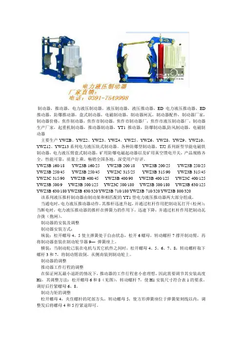
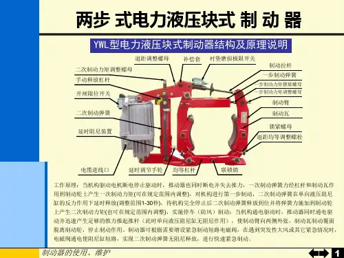
YWZ3B-160/18 YWZ3B-160/25 YWZ3B-200/18 YWZ3B-200/25 YWZ3B-250/25 YWZ3B-250/45 YWZ3B-250/45 YWZ3C-315/25 YWZ3B-315/90 YWZ3B-315/45 YWZ3C-315/90 YWZ3B-400/45 YWZ3B-400/90 YWZ3B-400/125 YWZ3C-400/125 YWZ3B-500/9 YWZ3B-500/125 YWZ3C-500/180 YWZ3B-500/180 YWZ3B-630/125 YWZ3B-630/180 YWZ3B-630/320 YWZ3B-710/180 YWZ3B-710/320 YWZ3B-800/320该系列液压推杆制动器由制动架和相匹配的YT1型电力液压推动器两大部分组成。
当通电时,电力液压推动器动作,其推杆迅速升起,并通过杠杆作用把制动瓦打开(松闸);当断电时,电力液压推动器的推杆在弹簧力的作用下,迅速下降,并通过杠杆作用把制动瓦合拢(抱闸)。
制动器的安装及调整制动器安装方式:纵装:松开螺母4、5使主弹簧处于自由状态,松开6螺母,转动螺杆7撑开制动臂,再将制动器套装在制动轮节器9—弹簧座上。
YWZ9电力液压块式制动器设计总体方案及关键技术解决方法(1)、总体方案YWZ9电力液压块式制动器总体设计的指导思想是在安装、调整、维修方面减少很大的工作量,确保在高空或操作人员无法直接观察其使用状况等恶劣工作环境条件下使用,并保证其安全、可靠、使用经济、性能优良。
采用退距自动均等、自动润滑等国内独创结构装置,减少安装、调整、维修的工作量,提高主机生产效率。
采用Ed或YTD5推动器,安全、可靠、节约电能。
(2)、关犍技术①、一改过去老产品制动器的双臂为单臂焊接件,加工简单、工艺性好,加工精度高且省材。
装配方便、机械性能好,制动效率高。
②、制动器力矩调试显示直观、精确。
③、制动衬垫采用石棉材料或钢背半金属摩擦材料,较好地改善了摩擦性能,提高了摩擦材料的稳定性、耐磨性。
采用目前国际上较先进的无石棉材料,与常规的石棉刹车带和石棉树脂比较起来使用寿命提高两倍以上,提高了摩擦材料的利用率且制动期间无粉尘,不污染环境。
当前国际上先进国家制动器的发展不但要求制动器性能先进,而且要符合环保要求,该制动衬垫正具备此特点。
④、多年来,国内制动器产品制动衬垫的固定方式一直采用铆接式和压板组装式。
铆接式连接费时又不省材,压板组装式连接虽然维修更换方便,但制动衬垫利用率低、浪费严重。
YWZ9电力液压块式制动器制动衬垫的固定采用插入式连接,克服了制动衬垫的轴间窜动,省略了挡板,不但更换维修方便,而且制动器衬垫的利用率可提高30%,并且减少了固定中的一些零件,省材、省时。
⑤、制动器各铰接处增加了自润滑轴承,提高了零件的耐磨性和制动效率,克服了原来制动器铰接孔磨损后松不开闸的弊病。
制动器的闸瓦、底座铰接孔安装了注油杯,与同类产品相比,其制动效率得到较大提高。
⑥、YWZ9电力液压块式制动器在安装调试方面,与现有产品相比,性能优越,在拉杆与弹簧拉杆调整处加了隔套,使其安装调整更加方便。
⑦、采用Ed或YTD5液压推动器,比同规格电磁铁块式制动器节电约40%,且Ed推动器还可满足用户多种功能的需求,如加装行程开关、多方位安装等。
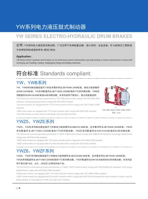
符合标准 Standards compliant:应用:YW 系列电力液压鼓式制动器,广泛应用于各种起重运输、港口装卸、冶金设备、矿山机械及工程机械中各种机构的减速和停车(维持)制动。
Application:YW Seires electro-hydraulic drum brakes can be extensively used for deceleration and stop/braking of various mechanisms in various belt conveying, port handling, hoisting, metallurgical,mining and building machinery.YW 、YWB 系列制动器连接尺寸和技术要求符合JB/T6406-2006标准,制动力矩参数符合DIN15435标准;YW 系列配套符合JB/T10603-2006标准的YTD 系列推动器;YWB 系列配套符合DIN15430标准的Ed 系列推动器;本系列适用于新设计、新主机配套选用。
The dimensions and technology requirements of YW,YWB series brakes comply with JB/T6406-2006 standard, braking torque parameters comply with DIN15435 standard;YW series brakes are equipped with YTD series thrusters which comply with JB/T10603-2006 standard.YWB series brakes are equipped with YTD series thrusters which comply with DIN15430 standard.This series brakes is mainly used for new design and new main machines.YW 、YWB 系列YWZ5、YWZE 系列YWZ6、Y WZF 系列YWZ5、YWZE 系列制动器连接尺寸和制动力矩参数符合GB6333-86标准,技术要求符合JB/T6406-2006标准;YWZ5系列配套符合JB/T10603-2006标准的YTD 系列推动器;YWZE 系列配套符合DIN15430标准的Ed 系列推动器。
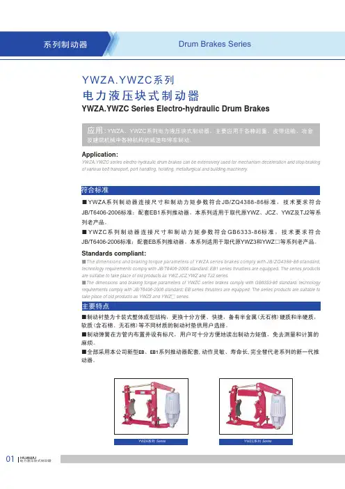
Application:YWZA,YWZC series electro-hydraulic drum brakes can be extensively used for mechanism deceleration and stop/braking of various belt transport, port handling, hoisting, metallurgical and building machinery.■YWZA 系列制动器连接尺寸和制动力矩参数符合JB/ZQ4388-86标准,技术要求符合JB/T6406-2006标准;配套EB1系列推动器。
本系列适用于取代原YWZ 、JCZ 、YWZ 及TJ2等系列老产品。
■YWZC 系列制动器连接尺寸和制动力矩参数符合GB6333-86标准,技术要求符合JB/T6406-2006标准;配套EB 系列推动器。
本系列适用于取代原YWZ3和YWZ □等系列老产品。
Standards compliant:■The dimensions and braking torque parameters of YWZA series brakes comply with JB/ZQ4388-86 standard, technology requirements comply with JB/T6406-2006 standard; EB1 series thrusters are equipped. The series products are suitable to take place of old products as YWZ ,JCZ ,YWZ and TJ2 series.■The dimensions and braking torque parameters of YWZC series brakes comply with GB6333-86 standard, technology requirements comply with JB/T6406-2006 standard; EB series thrusters are equipped. The series products are suitable to take place of old products as YWZ3 and YWZ □ series.YWZA.YWZC 系列电力液压块式制动器YWZA.YWZC Series Electro-hydraulic Drum BrakesYWZA 系列 SeriesYWZC 系列Series ■制动衬垫为卡装式整体成型结构,更换十分方便、快捷,备有半金属(无石棉)硬质和半硬质,软质(含石棉、无石棉)等不同材质的制动衬垫供用户选择。

电力液压制动器YWZ-300/45正常工作条件环境温度-20℃~40℃;完全相对湿度不大于90%;在无爆炸危险的介质中,且介质中无足以腐蚀和破坏绝缘的气体和导电尘埃的环境中;安装地点的海拔高度符合GB755-87标准,适用于三相380V,50Hz交流电源。
电力液压制动器YWZ-300/45主要技术参数型号匹配推动器制动力矩N.M 退矩 b C D d F G1 G2 H h1 i K MYWZ-100/18 MYT1-18ZB/2 40 0.6 70 137 100 13 75 125 125 384 100 40 110 138 YWZ-150/25 MYT1-25ZB/4 100 0.6 90 154 150 17 100 170 170 437 140 60 150 138 YWZ-200/25 MYT1-25ZB/4 200 0.7 90 154 200 17 100 195 195 440 170 60 175 156 YWZ-300/25 MYT1-25ZC/4 320 0.7 140 154 300 22 130 280 280 692 240 80 250 200 YWZ-300/45 MYT1-45Z/5 630 0.7 140 178 300 22 130 280 280 600 240 80 250 200 YWZ-400/45 MYT1-45Z/6 1000 0.8 180 178 400 22 180 360 360 735 320 130 325 265 YWZ-400/90 MYT1-90Z/8 1600 0.8 180 210 400 22 180 360 360 740 320 130 325 265 YWZ-400/125 MYT1-125Z/10 2200 0.8 180 254 400 22 180 360 360 850 320 130 325 271YWZ-500/125 MYT1-125Z/10 2650 0.8 200 210 500 22 200 415 415 885 400 150 380 310YWZ-600/90 MYT1-90Z/8 3200 0.8 240 210 600 26 220 505 520 1082 475 170 475 390YWZ-600/180 MYT1-180Z/12 5000 0.8 240 254 600 26 220 505 520 1082 475 170 475 390YWZ-700/180 MYT1-180Z/12 8000 0.8 280 254 700 34 270 580 600 1225 550 200 540 585YWZ-800/180 MYT1-180Z/12 10000 0.8 320 254 800 34 320 677 697 1417 600 240 620 510YWZ-800/230 MYT1-320Z/12 12500 0.8 320 375 800 34 320 677 697 1417 600 240 620 1100电力液压制动器YWZ-300/45用途YWZ系列电力液压块式制动器,采用MYT1系列推动器作为制动器的驱动装置。
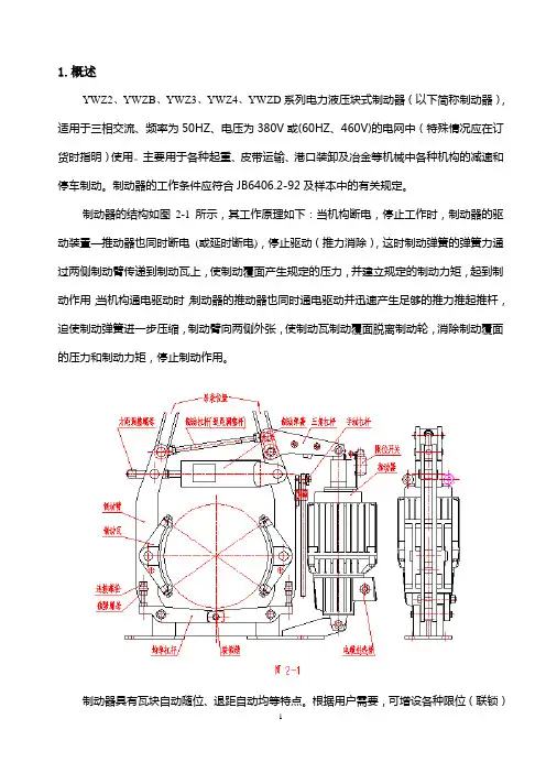
1.概述YWZ2、YWZB、YWZ3、YWZ4、YWZD系列电力液压块式制动器(以下简称制动器),适用于三相交流、频率为50HZ、电压为380V或(60HZ、460V)的电网中(特殊情况应在订货时指明)使用。
主要用于各种起重、皮带运输、港口装卸及冶金等机械中各种机构的减速和停车制动。
制动器的工作条件应符合JB6406.2-92及样本中的有关规定。
制动器的结构如图2-1所示,其工作原理如下:当机构断电,停止工作时,制动器的驱动装置—推动器也同时断电(或延时断电),停止驱动(推力消除),这时制动弹簧的弹簧力通过两侧制动臂传递到制动瓦上,使制动覆面产生规定的压力,并建立规定的制动力矩,起到制动作用;当机构通电驱动时,制动器的推动器也同时通电驱动并迅速产生足够的推力推起推杆,迫使制动弹簧进一步压缩,制动臂向两侧外张,使制动瓦制动覆面脱离制动轮,消除制动覆面的压力和制动力矩,停止制动作用。
制动器具有瓦块自动随位、退距自动均等特点。
根据用户需要,可增设各种限位(联锁)开关。
它往往是现代化起重运输及高效装卸设备所必须的。
限位开关的作用是给司机室(控制室)或PLC控制提供制动器的某些特定状态的监控(故障显示)或联锁保护信号。
比如:开闭闸限位开关可向控制室提供制动器是否正常开闸或闭闸的信号显示,也可通过它来进行某些联锁保护,闭闸限位开关一般不常用;手动开闸限位开关是为了操作安全而设置的,当手动开闸装置处于开闸状态时,限位开关将对主机进行自动联锁,此时主机是不能开动的,从而确保操作安全。
限位开关的型号一般为WL双路限位开关(日本Omron产品)或3SE3 120-OF、3SE3 120-OGG.H.K)(按西门子许可证生产的产品)等,也可由用户选定。
制动器还可根据需要增设手动释放装置及其安全联锁开关,当电网因故障或其它原因停电时,需要开闸释放制动器,可通过用手动释放装置进行松闸和控制。
其操作方法见图2-1,只需将手动杠杆向上扳起即可。
YWZ5电力液压块式制动器广泛用于起重、冶金、矿山、港口、码头、建筑等机械驱动装置的减速和停车制动。
其安装尺寸和制动力矩参数符合JB/T6046-2006标准。
匹配Ed系列推动器性能安全可靠、制动平稳、动作频率高、制动力矩可调。
主要摆动铰点设自润滑轴承,传动效率高、寿命长,在使用过程中始终保持两侧瓦块退距均等,避免因退距不均使一侧制动衬垫浮帖制动轮的现象。
制动弹簧布置在弹簧管内,并在一侧设有制动力矩标尺,调整方便,直观。
可通过增设附加装置实现某些附加功能:手动释放装置释放(开闸)或闭合(闭闸)限位开关,可实现制动器是否正常释放或闭合的信号显示或连锁保护。
采用带下降延时阀的推动器推动,可实现制动器的延时闭合。
使用条件和规程:环境温度: -25℃~+45℃。
空气相对湿度:≤90%海拔高度:符合GB755-2000标准。
电源:三相交流50Hz·380V. (根据用户要求也生产用于要求可提供60Hz或不同电压的产品。
适应的工作制:连续(S1)和断续(S3-60%)工作制。
二、使用条件1、环境温度-20℃~+50%(低于推动器改为YH-10航空液压油)2、空气相对湿度不大于90%3、一般用于三相交流电源,50HZ,380V;4、海高度符合GB755-87标准;5、在无爆炸危险,且介质中无足以腐蚀金属和破坏绝缘的气体及放电尘埃中;6、YZW、YZW3使用YTI系列推动器,一般适用于垂直工作,倾斜度不超过±去15°三、产品型号及意义四、外形尺寸图五、YWZ5技术数据、外形尺寸表(毫米) 型号匹配推动器 制动力矩 牛顿·米 退距 A b C d D E F G1 G2 H h1 i K M n 重量YWZ5-160/23 Ed23/5 180 0.8 428 65 160 160 14 150 85 144 191 395 132 55 130 110 8 20 YWZ5-200/23 Ed23/5 112-224 1 448 80 160 100 14 165 90 165 195 487 160 55 145 120 15 27 YWZ5-200/30 Ed30/5 140-315 445 33 YWZ5-250/23 Ed23/5 140-224 1.25 503 100 160 250 18 200 100 200 223 553 190 65 180 145 17 38 YWZ5-250/30 Ed30/5 180-315 500 44。
电力液压制动器YWZ-300/45正常工作条件环境温度-20℃~40℃;完全相对湿度不大于90%;在无爆炸危险的介质中,且介质中无足以腐蚀和破坏绝缘的气体和导电尘埃的环境中;安装地点的海拔高度符合GB755-87标准,适用于三相380V,50Hz交流电源。
电力液压制动器YWZ-300/45主要技术参数型号匹配推动器制动力矩N.M 退矩b C D d F G1 G2 H h1 i K MYWZ-100/18 MYT1-18ZB/2 40 0.6 70 137 100 13 75 125 125 384 100 40 110 138YWZ-150/25 MYT1-25ZB/4 100 0.6 90 154 150 17 100 170 170 437 140 60 150 138YWZ-200/25 MYT1-25ZB/4 200 0.7 90 154 200 17 100 195 195 440 170 60 175 156YWZ-300/25 MYT1-25ZC/4 320 0.7 140 154 300 22 130 280 280 692 240 80 250 200YWZ-300/45 MYT1-45Z/5 630 0.7 140 178 300 22 130 280 280 600 240 80 250 200YWZ-400/45 MYT1-45Z/6 1000 0.8 180 178 400 22 180 360 360 735 320 130 325 265YWZ-400/90 MYT1-90Z/8 1600 0.8 180 210 400 22 180 360 360 740 320 130 325 265YWZ-400/125 MYT1-125Z/10 2200 0.8 180 254 400 22 180 360 360 850 320 130 325 271YWZ-500/125 MYT1-125Z/10 2650 0.8 200 210 500 22 200 415 415 885 400 150 380 310YWZ-600/90 MYT1-90Z/8 3200 0.8 240 210 600 26 220 505 520 1082 475 170 475 390YWZ-600/180 MYT1-180Z/12 5000 0.8 240 254 600 26 220 505 520 1082 475 170 475 390YWZ-700/180 MYT1-180Z/12 8000 0.8 280 254 700 34 270 580 600 1225 550 200 540 585YWZ-800/180 MYT1-180Z/12 10000 0.8 320 254 800 34 320 677 697 1417 600 240 620 510YWZ-800/230 MYT1-320Z/12 12500 0.8 320 375 800 34 320 677 697 1417 600 240 620 1100电力液压制动器YWZ-300/45用途YWZ系列电力液压块式制动器,采用MYT1系列推动器作为制动器的驱动装置。
YWZ5-200/30 电力液压块式制动器
YWZ5-200/30电力液压制动器 YWZ5电力液压推杆制动器 YWZ5制动器 YWZ5液压制动器
广泛用于起重、冶金、矿山、港口、码头、建筑等机械驱动装置的减速和泊车制动。
其安装尺寸和制动力矩参数符合JB/T6046-2006尺度。
匹配Ed系列推动器
机能安全可靠、制动平稳、动作频率高、制动力矩可调。
主要摆动铰点设自润滑轴承,传动效率高、寿命长,在使用过程中始终保持两侧瓦块退距均等,避免因退距不均使一侧制动衬垫浮帖制动轮的现象。
制转动簧布置在弹簧管内,并在一侧设有制动力矩标尺,调整利便,直观。
可通过增设附加装置实现某些附加功能:
手动开释装置
开释(开闸)或闭合(闭闸)限位开关,可实现制动器是否正常开释或闭合的信号显示或连锁保护。
采用带下降延时阀的推动器推动,可实现制动器的延时闭合。
使用前提和规程:
环境温度: -25℃~+45℃。
空气相对湿度:≤90%
海拔高度:符合GB755-2000尺度。
电源:三相交流50Hz·380V. (根据用户要求也出产用于要求可提供60Hz或不同电压的产品。
适应的工作制:连续(S1)和断续(S3-60%)工作制。
电力液压块式制动器说明及调整标准一、结构及工作原理1、电力液压块式制动器由制动架和相匹配的电力液压推动器两大部分组成,当通电时,电力液压推动器动作,其推杆迅速升起,并通过杠杆作用把制动瓦打开(松闸);当断电时,电力液压推动器的推杆在制动弹簧力的作用下,迅速下降,并通过杠杆作用把制动瓦合拢(抱闸)二、制动器的安装与调整:1、准备1.1抱闸的安装由维修人员负责,调整由生产车间设备技术人员负责,岗位人员监护;1.2开具制动器安装调整作业票;1.3停机、断电、打零位、挂牌、上锁;1.4解下电机防尘罩并放置妥当(根据现场情况联系电工接拆电)2、安装2.1 安装前的检查:2.1.1 检查制动器在运输或储存过程中是否有损坏或缺件。
2.1.2 检查制动器表面是否清洁,若有油污或其他赃物,应彻底清除干净。
2.2 安装:2.2.1 根据制动器在主机的安装位置,确定出制动器的维修、调整空间较大或较方便的一侧。
如果瓦块随位调整装置13和退距均等装置16不在维修空间一侧时,可将其卸下装在同侧2.2.2纵装:首先旋转弹簧拉杆6,使制动弹簧力达到最小值,然后转动拉杆10撑开两制动臂,再将制动器套装在制动轮上。
2.2.3 横装:当制动轮已安装在电机或其他机件之间时,首先卸下螺栓14背面的螺母,使其与退距均等装置16脱离,然后打出销轴15,将制动臂11向上掀起,从侧面装到制动轮上,安装好以后再将以上卸掉的零件重新装上。
2.2.4 安装后,应对制动器的各个性能进行检验。
3、制动器调整:3.1 推动器工作行程的调整:首先将弹簧力释放到最小值,然后旋转拉杆10,使制动器处于闭合状态,继续旋转,这时推动器推杆慢慢升起,当升起高度H达到规定尺寸(一般10-15mm)时,即完成调整。
随着闸皮的磨损,H值逐渐减小,当减到最小值H min(一般5mm)时,需及时按以上方法重新调整,否则失去制动作用。
3.2 瓦块随位的调整:在制动器处于抱闸状态时,旋转瓦块随位调整装置13中的螺栓,使其顶端与制动瓦筋板轻轻接触,并锁紧螺母。