AUTOMAT ULTRA系列光电自准直仪用户手册_REV.D
- 格式:pdf
- 大小:3.40 MB
- 文档页数:70
激光准直仪操作规程激光准直测量系统由半导体激光器、光学分光及转向系统、光电接收系统及液晶显示模块组成。
激光光束经转向系统后出射两条相互平行的基准光束,作为导轨的安装检测基准。
该系统利用二维PSD作为光电接收器件,采用液晶显示模块显示导轨偏差,可快速、直接、准确地测量导轨安装的偏移量,从而提高导轨安装的精度和速度。
实验结果显示测量系统在X,Y方向上的标准偏差分别为:0.002mm,0.005mm。
1、主要参数2、主机由半导体激光器、空间位相调制器、壳体、底座、和电源所组成。
3、激光准直仪的特点与工作原理1)仪器的特点是采用了空间位相调制器。
激光束在任意测距上,其横截面均为一组良好的、红黑反差很大的同心圆环,中心光斑亮且小,利于定位。
而且在不同测距进行测量时是不用调焦的,实现了无调焦运行差。
中心光斑直径随着工作距离的增大而增大,符合下列参数:L=2.5米时Ø0.1mmL=20米时Ø1.2mmL=50米时Ø2.5mm2)将仪器固定在主机的回转轴上后用百分表测量仪器端部的测环在盘车处于不同位置时的差值,通过调整仪器底座上的调整螺钉,使其差值越来越小,只要主机轴系配合良好,可以调至±0.02~0.03mm。
然后利用置于远离主机15米左右的平面反射镜,将仪器射出的激光束反射至位于仪器附近的测微光靶。
在主机盘车时调整仪器壳体上的四只调整螺钉,(必要时适当调整反射镜的角度),使反射回来的激光束画的圆的半径越来越小,最后调至±0.1mm以内为止,此时应再次检查盘车360°时,百分表所显示波动值的范围和测微光靶的测量差值,准确无误时即可用此光轴代替主机的机械轴。
3)二维测微光靶二维测微光靶是用来记录与测量主机盘车时光轴的变化量。
二维测微光靶是由光靶和在X、Y两个自由度上测微的百分表所组成,光靶本身带有卡具和折射棱镜,为安装和读数提供了方便条件。
测微光靶的工作范围是±4.5mm。

工具操作手册目录一、UT311测振仪 (3)仪器简介 (3)工作原理 (3)仪表结构 (3)符号 (4)使用方法 (4)测量范围 (4)保养维护 (5)二、UT71E数字万用表 (5)仪器简介 (5)安全使用准则 (5)外形结构 (5)旋钮开关及按键功能 (6)测量操作说明 (6)按键功能定义 (9)保养与维修 (11)三、UT233数字钳形功率计 (12)仪器简介 (12)仪器结构图 (12)LCD显示.................................................... . (14)按键功能 (14)测量 (14)电池更换 (19)四、UT372非接触式转速计............................... (19)仪器简介 (19)仪器结构图 (19)LCD显示................................... (20)按键功能及设置 (20)测量操作说明 (21)五、UT320S数字式测温仪................................ (22)仪器简介 (22)仪器结构图 (22)LCD显示.................................. ......................... .. (22)按键功能 (23)仪表设置 (24)仪表使用 (25)六、UT342覆层测厚仪............ .. (25)仪器简介 (25)LCD显示 (25)基本测量 (26)七、UT332数字式温湿度表 (26)仪器简介 (26)仪器外观 (26)仪表设置 (26)仪表使用 (27)保养维护 (28)八、UT360风速仪 (28)仪器简介 (28)仪表外观 (28)LCD显示 (29)按键说明 (29)仪表使用 (30)保养维护 (31)九、UT352声级计 (31)仪器简介 (31)仪器外观 (31)按键功能及设置 (31)外观 (32)十、UT202数字钳式万用表 (32)仪器简介 (32)操作说明 (32)保养维护 (33)一、UT311测振仪1.仪器简介UT311型测振仪是由加速度和数字测量显示电路构成的一体式手持测振仪表。

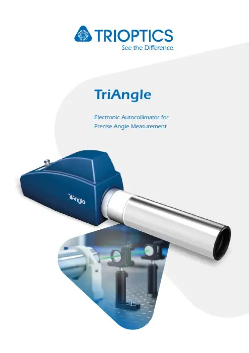
TriAngleElectronic Autocollimator for Precise Angle MeasurementLEADING TO THE FUTURE OF OPTICSOptical systems have changed the world.And they will continue to do so.TRIOPTICS is significantly involved in this process.We see ourselves as a solution provider for optical measurement and manufacturing systems andoffer our customers the right system for their current and future applications.2Key FeaturesTriAngle Electronic Autocollimators• Electronic Autocollimators for Optical Angle Measurement• Measurement of angular displacements with highest accuracy • Wide range of application specific variants with a modular design • Effective focal lengths from 100 – 1000 mm• Different sensors, reticles and light sources available• Accuracy performance up to 0.05 arcseconds• OptiAngle Software package for angle measurements4IlluminationFilter Condensor Object ReticleDiffusorObjective LensSensorBeam SplitterDigital CameraPrinciple of an Electronic AutocollimatorThe autocollimator combines both optical tools, the collimator and the telescope into one instrument using a single objective lens. Both beam paths are seperated by using a beam splitter. The autocollimator is a very sensitive angle measuring device and is thus used for the precise angular adjustment of optical or machine components. Due to the collimated beam (infinity adjustment) the measurement results are independent from the distance to the object under test.In an electronic autocollimator the eyepiece is replaced by an electronic camera with discrete sensor pixels (e.g. CCD or CMOS sensor type). It can be of a 2D frame type allowing angular measurements in two directions, or a 1D line scan sensor for single axis measurements. The digital camera is usually connected to a PC which calculates the measured angle from the image by using image analysis software. The high resolution of electronic autocollimators is due to the evaluation of gray scale levels in the image which allows for sub pixel interpolation of the image position. Depending on the focal length of the objective lens and the stability of the setup, angular resolutions of 1/100 up to 1/1000 arcsecs can be achieved.TriAngle Electronic AutocollimatorThe TriAngle electronic autocollimators are non-contact optical test tools for thehigh-precision measurement of angular displacements of specular reflective surfaces andthe accurate angular alignment of optical or mechanical parts.TriAngle autocollimators have a versatile modular design which allows them to be fitted with a wide selection of objective tubes, different sensors, reticles and light sources. With objective tubes of different focal lengths and apertures, the optimum measurement solution regarding angle resolution and measurement range is easily found.TriAngle autocollimators are available in different application-specific variants:TriAngle TriAngle UltraSpecTriAngle UVTriAngle Laser TriAngle Large Field TriAngle Vacuum5TriAngleProductgroup overviewTriAngleThe standard instrument offering a maximum set of measurement functions.• LED light source of 525 nm• High resolution camera• Focal lengths ranging from 100 mm to 1000 mm• Accuracy performance of up to 0.2 arcsecTriAngle UltraSpecFor highest demands on angle resolution and measurement accuracy.• LED light source of 525 nm• High resolution camera with extremely low sensor noise• Objective lens of minimum distortion• Thermally and mechanically optimized design• Focal lengths 300 mm or 500 mm• Accuracy performance of up to 0.05 arcsec• Calibrated with PTB angle standardsTriAngle FocusFor the measurement of slightly spherical surfaces.• LED light source of 525 nm• Focusing objective tubes• Focal lengths ranging from 100 mm to 1000 mm• A ccuracy performance of up to 0.2 arcsec(higher resolution on demand)6TriAngle HighSpeedIdeal for vibration measurements or rapidly moving samples.• L aser illumination of 635 nm allows the measurement ofvery small and low reflective surfaces• H igh bandwith position-sensitive photo detectorfor angle measurement rates up to 10 kHz• The position sensitive detector emits almost no heat• Focal lengths ranging from 100 mm to 1000 mmTriAngle NIRFor applications that require measurementat the design wavelengths in the NIR.• L ight source with 1064 nm(other wavelengths available on request)• Focal lengths ranging from 100 mm to 1000 mm• Accuracy performance of up to 0.2 arcsecTriAngle UVFor applications that require measurementat the design wavelengths in the UV.• L ight source with 365 nm(other wavelengths available on request)• F ocal lengths ranging from 100 mm to 1000 mm• A ccuracy performance of up to 0.2 arcsec7TriAngleTriAngle LaserIdeal for the measurement of small optical components, surfaces of low reflectivity orlong distance measurements.• L aser illumination with wavelengths of 635 nm • F ocal lengths ranging from 100 mm to 1000 mm • A ccuracy performance of up to 0.25 arcsecTriAngle Large FieldFor applications requiring a large measuring range without compromising the measurement accuracy and resolution.• L ED light source of 525 nm• S pecially calibrated large field sensor and optimized imaging optics• A vailable with a focal range of 100 mm• A ccuracy +/- 1“ within 80 % measuring rangeTriAngle VacuumThe right choice for special applications in space science and high-energy physics.• Vaccuum compatible from rough to high vacuum89Typical TriAngle ApplicationTilt Angle Measurement Prism & Polygon MeasurementAlignment of Optical Components Measurement of Slightly Curved SurfacesWedge Angle Measurement in Reflection / Double PassMeasurement ofFlatness / Straightness / ParallelismWobble & Vibration MeasurementRotary Table CalibrationSoftwareOptiAngle®: The Complete Software Package for Angle MeasurementThe OptiAngle® software is a powerful tool covering all aspects of accurate angle measurement with the TriAngle electronic autocollimators in terms of measurement, control and analysis of the angular data. The well organized and modern menuguided user interface assists even the inexperienced operatorto perform accurate measurements and to obtain repeatable results. A large set of predefined stan-dard measurement applications is integrated into OptiAngle which cover all established measurement techniques in optical and mechanical industry. In addition, customized measurement routines canbe easily developed and embedded either by TRIOPTICS or the experienced end user. All OptiAngle®measurement functions can be further used in other common applications like Lab-View orVisual Basic (Excel).OptiAngle® software for electronic autocollimators1011Software Features and FunctionsThe TriAngle software provides many features to simplify the daily use of TriAngle autocollimators whether in the laboratory or in the production environment.• R eal-time camera display• N umerical and graphical display of measure-ment data• O ptional full screen camera window (visual alignment mode)• U ser defined graphical scales or indicators inside the camera window• S imultaneous measurement with multiple (up to 12) autocollimators• S imultaneous measurement of multiple surface reflections (up to 12)• C omprehensive data reporting functions • A SCII (CSV) data export• S electable angle units for screen display and measurement certificate• S oftware remote control by host computer via RS232 interface and TCP / IP• P lug-in mechanism for customized measure-ment programs• U ser defined measurement certificate layout • D emo programming examples for Excel, LabView, VBA• M ultiple camera interface technology for USB, IEEE 1394 (Firewire), Gigabit Ethernet, Camera-Link or Analog Video Camera• P roduction mode for batch/lot sample identification and result reportingTriAngle modular software conceptMeasurement taskYour ApplicationC++ APIOperating SystemTCP / IP Your Development EnvironmentRS232OptiAngle ®12AccessoriesIn addition to the TriAngle electronic autocollimator series, TRIOPTICS offers a large range of opto-mechanical accessories, often required for certain standard applications.HoldersClamp FixtureAdjustable HoldersStands• M anual Stand• 2-axes vertical mount D38, D57• F ixture for wedge measurement • T ripodAlignment ToolsLaser Prealignment ToolView Finder Prism• V iew Finder PrismClamp fixtureAdjustable holderLaser PreAlignment Tool13MirrorsMirrors• M irror in mount • A djustable mirrorsRedirecting Mirrors• 45° redirecting mirror for D38, D57, D115• P enta PrismCalibration Tools90° Reference Prism in MountPolygons• P olygon 12 sides in holderCalibration WedgesMirror in mountRedirecting mirrorPenta Prism in holderPolygonProduct overview TriAngle1415FRANCETAIWANJAPANCHINABERLINKOREA WetzlarUSAWest Coast OfficeUSAEast Coast OfficeFRANCEBERLINWetzlarTRIOPTICS worldwideLocationsGermanyTRIOPTICS GmbH Strandbaddamm 6 22880 Wedel, Germany Tel.: +49 4103 18006-0 ******************* TRIOPTICS GmbH Wetzlar Branch Tel.: +49 6441 4454 910 ******************* TRIOPTICS Berlin GmbH Tel.: +49 30 6392 3456 ****************************ChinaTRIOPTICS China Tel.: +86 010 ******** ************************TaiwanTRIOPTICS Taiwan Ltd. Tel.: +886 3 4620405 *****************RussiaJSC URANTel.: +7 812 335 0975 ****************www.uran-spb.ruFranceTRIOPTICS France Tel.: +33 4 72 44 02 03 ********************www.trioptics.frUSATRIOPTICS, Inc. Tel.: +1 626 962 5181 ***********************TurkeyOptomek Optical Mechanical Engineering Industry and Trade Ltd. Co. Tel.: +90 312 219 4422 ****************.tr .trJapanTRIOPTICS Japan Co.,Ltd. Tel.: +81 54 203 4555 *****************www.trioptics.jpIndiaHP Instruments Tel.: +91 80 25521990 *********************United KingdomArmstrong Optical Ltd. Tel.: +44 1604 654220 ************************.uk KoreaTRIOPTICS Korea Co.,Ltd. Tel.: +82 31 695 7450 *****************.kr www.trioptics.co.krIsraelProlog Optics Ltd. Tel.: +972 3536 4011 ******************93-015-100-E N V e r s i o n 003。
二维光电自准直仪操作手册鞍山光准科技有限公司鞍山光准科技有限公司二维光电自准直仪操作手册目录1保修及有限责任 (1)维护 (1)功能和损坏的责任 (1)附件 (1)安全说明 (1)2设计用途 (2)3功能描述 (3)3.1二维光电自准直仪简介 (3)3.1.1自准直原理 (3)3.1.2主要技术指标 (4)3.1.3自准直仪主要功能 (5)3.1.4自准直仪主要特点 (5)3.2部件描述 (6)3.2.1自准直测头 (6)3.2.2网络连接线和电源箱 (6)3.2.3电脑 (7)3.2.4二维摆角调整底座 (7)3.2.5反射镜 (7)3.2.6激光找像器 (7)4软件介绍 (8)4.1整体界面 (8)4.1.1控制区 (8)4.1.2 显示区 (9)4.2菜单栏 (10)5操作 (13)5.1单位 (13)5.2标定 (13)5.3绝对测量与相对测量 (14)5.4有效位数设置 (14)5.5实时采集和单帧采集 (15)5.6自动测量和手动测量 (16)5.7动态测量和单次测量 (16)5.8数据的保存和查看 (17)5.9量程扩展 (17)5.10刻度显示 (18)5.11公差显示 (18)6测量 (20)6.1直线度测量 (20)6.1.1准备 (20)6.1.2输入 (20)6.1.3采样 (21)6.1.4查看结果 (22)6.1.5生成word (24)6.2平面度测量 (25)6.2.1网格布点法平面度测量 (25)6.2.2对角线布点法平面度测量 (30)6.3平行度测量介绍 (34)6.4垂直度测量介绍 (34)7附录: (35)1保修及有限责任维护该光电自准直仪在更改或维护时只能使用鞍山光准科技有限公司提供的原装部件,并且只能由鞍山光准科技有限公司明确授权的人员进行。
功能和损坏的责任该光电自准直仪如因维护不当或者由非鞍山光准科技有限公司明确授权的人员进行更改导致的仪器不能正常运行,或得不到精确结果,鞍山光准科技有限公司不承担任何责任。
Tru Pointe ®UltraUltrasonic Leak DetectorInstruction 0028-9000Operation and MaintenanceRev. 1 - May 2010The Measurable Difference®WARRANTYThe Bacharach Tru Pointe® Ultra is warranted for one year to be free of manufacturing defects adversely affecting performance. Should an instrument fail within the one year warranty period, the unit will be repaired or replaced provided in the opinion of the factory, the instrument has not been tampered with or abused.If defective, return to the factory for repair and re-calibration. Maximum liability of Bacharach shall be limited to replacement of unsatisfactory product.Recommendations and product information are believed to be accurate, but the furnishing of it does not constitute the making of a good process warranty of Seller.Bacharach warrants that this product conforms to the Product Description contained in this literature. Bacharach makes no other warranty, whether expressed or implied, including warranties of merchantability or of fi tness for a particular purpose or application. No statements or recommendations contained herein are to be construed as inducements to infringe any relevant patent, now or hereafter in existence. Bacharach neither assumes nor authorizes any representatives or other person to assume for it any obligation of liability other than such as expressly set forth herein.Under no circumstances shall Bacharach be liable for incidental, consequential or other damages from any alleged negligence, breach of warranty, strict liability or any other theory, arising out of the use or handling of this product.Contents1 About This Manual (1)Warning Statements (1)Caution Statements (1)2 Introduction (2)General Description (2)What’s in the Kit (2)0028-8000 (2)0028-8010 (2)Features (2)3 Specifi cations (3)4 Operation (4)Physical (4)Taking Readings (4)General (4)Airborne Leak Detection (5)Operating Tips (6)Electrical Arcing (6)Electrical Corona (6)Using the Touch Probe (7)Thermal Expansion Valves (TXV) (7)Using the SoundBlaster® (8)SoundBlaster® Applications (9)5 Care and Service (10)Cleaning (10)Battery Replacement (10)Service (10)NOTES11 About This ManualThank you for investing in a Bacharach Tru Pointe ® Ultra Ultrasonic Leak Detector.To assure operator safety and the proper use of the Tru Pointe ® Ultra, please read the contents of this manual, which provides important information on the operation and maintenance of the detector.Warning StatementsThe use of the word WARNING (and the warning symbolat left) in this manual denotes a potential hazard associ-ated with the use of this equipment. It calls attentionto a procedure, practice, or condition, or the like, whichif not correctly performed or adhered to, could result inpersonal injury or death.Caution StatementsThe use of the word CAUTION (and the caution symbolat left) in this manual denotes a potential hazard associ-ated with the use of this equipment. It calls attentionto a procedure, practice condition, or the like, which ifnot correctly performed or adhered to, could result indamage to the equipment.2 IntroductionGeneral DescriptionThe Tru Pointe® Ultra Ultrasonic Leak Detector is an electronic instrument that detects the inaudible high frequency sound (ultrasound) of high pressure leaks and converts it to sound a human can hear. Using patented technology, the Tru Pointe® Ultra guides the user to a leak by quantifying the intensity of the ultrasound and converting it to sound the user can easily hear. The Tru Pointe® Ultra has been specifi cally designed for air conditioning and refrigeration (HVAC-R) leak detection. The Tru Pointe® Ultra is the only test system that can simultaneously detect the vacuum and high pressure leaks that can occur in HVAC-R systems. Since the instru-ment detects only sound, it is gas-independent and can be used to detect leaks at the speed of sound, without the delay seen with gas dependent “sniffers.”What’s in the Kit0028-8000Tru Pointe® Ultra KitTru Pointe® Ultra .......................0028-7000 Instruction Manual ....................0028-9000 Carrying Case...........................0028-0005 6” Wave Guide ..........................0028-0004 Touch Probe .............................0028-0003 Folding Hi-Fi Headsetw/ Volume Control ....................0028-0002 9v Battery .................................0204-0024 Warranty Card ..........................0006-88250028-8010Tru Pointe® Ultra Kit w/ SoundBlaster®Tru Pointe® Ultra .......................0028-7000 SoundBlaster® ..........................0028-7006 Instruction Manual ....................0028-9000 Carrying Case...........................0028-00056” Wave Guide ..........................0028-0004 Touch Probe .............................0028-0003 Folding Hi-Fi Headsetw/ Volume Control ....................0028-00029v Battery .................................0204-0024 Warranty Card ..........................0006-8825Features• Capable of detecting a 5 psi leak from a .005” hole from 20-30 feet (depending on back-ground noise.• Capable of detecting any gas that generates ultrasonic sound during fl ow, including vacuum leaks.• Not affected by wind or high concentrations of leaked refrigerants.• SoundBlaster® allows testing of items not under pressure. (0028-8010 only)23 Specifications34 OperationPhysicalTo begin using the Tru Pointe® Ultra, fi rst take a moment to become familiar with the unit’s controls in Figure 1 and 2.Figure 1.Figure 2.Taking ReadingsGeneral1. Put on the Headphones and plug them into the Headphone Jack on the right sideof the detector.2. Slide the Sensitivity Adjust toward the top of the instrument until it stops. The TruPointe® Ultra is now at full sensitivity.NOTE: Always begin testing at full sensitivity and adjustas needed to reduce background noise.3. Gently push and hold the On/Off Button to begin leak detection. Simultaneouslyadjust the sensitivity level to pinpoint the location of the leak.NOTE: The On/Off Button must be pressed to continueleak detection. Once the On/Off Button is released, thedetector will shut off.4Airborne Leak DetectionThe Tru Pointe® Ultra is capable of detecting airborne leaks from up to 40 feet away. When an ultrasonic signal generated from a leak is detected, it will be indicated by an increase in the LED meter and a rushing sound will be heard in the headset. This sound will become more intense, and the meter reading will increase as the instrument is drawn closer to the leak point.The Tru Pointe® Ultra detects the ultrasound a gas makes as it leaks. Similar to the familiar hiss a leak makes, a gas leak generates ultrasonic sound that humans cannot hear. This ultrasonic sound propagates like a microwave (in straight lines) and this property makes it possible to fi nd its source. It is a listening device not a Sniffer. Because of this, the Tru Pointe® Ultra can function in areas where strong winds or a concentration of fumes are present.A leak is any unwanted fl ow of a substance out of a system, or with vacuum, into a system. The sound made by leaks (refrigerant, compressed air, tire leak etc.) is mostly ultrasonic and cannot be heard by humans.The following describes how to effectively determine the location of an airborne leak using the Tru Pointe® Ultra.1. Press the On/Off Button. If there is signifi cant background noise and the LEDBargraph Display reads ‘10’, reduce the sensitivity until the LED’s disappear.2. While pressing the On/Off Button, scan the area of the suspected leak in a side-to-side motion.3. While scanning, listen to differences in the sounds detected.Mechanical Noise: Usually synchronized to machinemotion in the system and easy to identifyLeak Noise: A harsh hissing sound or bird song.NOTE: To become familiar with the different soundsdetected by the Tru Pointe® Ultra, listen to the sound ofan air hose at low pressure or an aerosol cleaning spray,then shake a set of keys. This demonstration allows theuser to distinguish between mechanical noise and leaknoise.4. If there is leak noise in the area and the display is at ‘10’, slowly reduce the sensi-tivity until the display reads ‘0’.NOTE: The LED Bargraph Display is only for relativemeasurements. If a scan of the system reveals an areawith a reading of ‘2’ and an area with a reading of ‘10’,that can mean the detector is far from a leak, or thereare two leaks of differing sizes in the same area.5. Approach the suspected leak. If the LED Bargraph Display reading increases,reduce the sensitivity.6. When the general location of the suspected leak is determined, adjust the sen-sitivity to so that 4-5 lights are illuminated when the leak area is scanned. Thistechnique allows the user to accurately determine when the instrument is pointedat an area of increased ultrasound. If the LED Bargraph display increases, thenthe leak source is getting closer. If the display decreases, then the leak source isgetting further away.56Operating Tips1.If the test area is large, remove the nose cone. Without the nose cone the detec-tion area of the Tru Pointe ® Ultra increases from 15° to 90°.2. If the leak is in a tight, or inaccessible area, use the supplied Wave Guide to deter-mine the leak location. Longer sections of 1/4” tubing can be used at the expenseof sensitivity.3. When searching for vacuum leaks, you may need to pressurize the system withdry nitrogen to facilitate locating the leak under pressure.4. Use as much pressure as permissible for the system. Increasing the pressure willmultiply fl ow through the same ori fi ce, increasing the ultrasound created by theleak.5.Interference may be experienced from electronic ballasts, computer monitors, orother electronic devices. Place your body between the source of the sound andthe leak point.Electrical ArcingElectrical arcing is an electric current fl ow in air and can be a very destructive and dangerous oc-currence in electrical systems.To search for electrical arcing, use the same methods described to search for airborne leaks, but scan around switches and electrical panels.NOTE: Electrical arcing sounds like frying, including theoccasional popping sound.CAUTION! Observe all all safety precautions whenworking around electrical equipment. Arcing can lead toexplosions.Electrical CoronaElectrical corona is usually observed in higher voltage systems than electrical arcing. Corona usually occurs in insulators, substations or transmission towers.To search for electrical corona, use the same methods described to search for airborne leaks.NOTE: Electrical corona sounds like frying or sizzling.CAUTION! Observe all safety precautions whenworking around electrical equipment.Using the Touch ProbeThe patented Touch Probe accessory is a device that converts solid-borne sounds into airborne sound the Tru Pointe® Ultra can detect. For example, the sound of an internal leak in a water valve will travel to its surface. Touching the surface of the valve with the Touch Probe transfers the ultrasound into the probe and converts it to airborne ultrasound.To install the Touch Probe:1. Unscrew the nose cone from the Tru Pointe® Ultra.2. Screw the Touch Probe onto the sensor.3. The Tru Pointe® Ultra is now ready to detect solid-borne sound.Thermal Expansion Valves (TXV)The following steps can be used to detect leaks in a TXV using the Touch Probe.1. Have a glass of ice water ready.2. Remove the TXV capillary tube.3. Rest the Touch Probe of the Tru Pointe® Ultra on the TXV and listen. Hold thecapillary. The TXV should open and the sound of fl owing refrigerant should beheard.4. Place the capillary in the ice water. The TXV should close and the refrigerant fl owdiminishing should be heard. If the fl ow binds or makes too much noise, theremay be a problem with the system.7Using the SoundBlaster ®Some Tru Pointe® Ultra kits include Bacharach’s ultrasonic sound generator, the SoundBlaster®. The SoundBlaster® is used to artifi cially pressurize items and detect potential leaks using a 115dB ultrasonic tone. The Tru Pointe® Ultra can detect the tone as it escapes in areas that are not under pressure.To use the SoundBlaster®:1. Press the On/Off Button once on the SoundBlaster®.2. Place the SoundBlaster® inside the item to be tested.3. Use the Tru Pointe® Ultra to detect the leaked ultrasonic waves generated by theSoundBlaster® using the same method as detecting a standard airborne leak.NOTE: Using the SoundBlaster® inside a symmetricalobject (i.e. a cylindrical tank) can cause standing waves,which can result in hot and cold spots. For these situa-tions push the ‘Mode’ button to turn the SoundBlaster®’sburst mode on.Tips on Use:1. Sound waves lose strength with distance, so when checking a building for leaks,do not place the SoundBlaster® in the basement and attempt to fi nd leaks in theroof.2. It is best to remove the nose cone from the SoundBlaster® when checking roofs3. If the SoundBlaster®’s tone is too strong, place a piece of sponge or foam in thenose cone.4. DO NOT place the nose cone fl at on a hard surface, as the refl ection of the gener-ated sound could damage the SoundBlaster®.8SoundBlaster® ApplicationsThe SoundBlaster® is an excellent tool for weatherizing buildings by detecting leaks in windows, doors and roofs. To effectively use the SoundBlaster® and Tru Pointe® Ultra to check for building leaks:1. Place the SoundBlaster® in the room to be leak tested and turn it ON2. From outside the room begin scanning for leaks with the Tru Pointe® Ultra aroundthe perimeters of the doors and windows.3. If the Tru Pointe® Ultra reading is at ‘10’, reduce the sensitivity until the detectorreads 4-5 and begin scanning again. Readings above the 4-5 threshold indicate alarger leak and should be fi xed prior to leaks that register under the threshold.4. A clear pattern of high and low readings should develop and pinpoint the locationof the highest priority leaks.Other SoundBlaster® applications include locating, air/water leaks in automobile windshields, trunk seal leaks, truck body leaks, and tanker leaks.95 Care and Service CleaningBoth the Tru Pointe® Ultra and SoundBlaster® can be cleaned using dish soap and a damp cloth. Remove the batteries and close the Battery Door before cleaning. Do not allow water to enter the unit, especially near the sensor. After cleaning, the units can be dried with a paper towel. Any automotive vinyl cleaner will restore the units luster.If you plan to store the units for an extended period, remove the batteries.Battery ReplacementWhen it is time to replace the batteries, use only high quality 9 volt alkaline for both the Tru Pointe® Ultra and the SoundBlaster®, and use the following instructions.1. Hold the unit with the Battery Door facing up.2. Press lightly on the middle of the Battery Door and slide it toward the bottom ofthe instrument.3. Remove the old battery and replace it.4. Slide the Battery Door back on the instrument, making sure it is securely attached. ServiceIf you need service, please contact Bacharach Customer Service (800-736-4666 or 724-334-5000) to obtain an RMA number for service returns. When you receive your RMA number, return the instrument, postage paid and insured to:Bacharach, Inc.8975 Marshall Ct., Suite 100Westminster, CO 80031Email:********************10NOTES11®The Measurable DifferenceBacharach, Inc.Phone: 724-334-5000 • Toll Free: 800-736-4666• Fax: 724-334-5001 •********************。
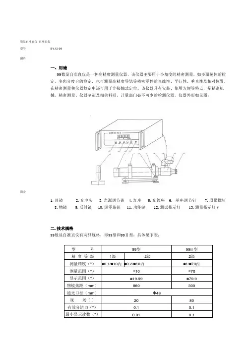
数显自准直仪自准直仪型号BY.12-99 图片简介一、用途99数显自准直仪是一种高精度测量仪器,该仪器主要用于小角度的精密测量,如多面棱体的检定、多齿分度台的检定,也可测量高精度导轨等精密零件的直线性、平行性、垂直性及相对位置,在精密测量和仪器检定中还可用于非接触式定位。
该仪器具有安装、使用方便等特点,是精密机械、精密测量、仪器制造及相关科研、计量部门必不可少的检测仪器。
仪器外形如见图:1.目镜2.光电头3.光源调节盖4.灯座5.光管座6. 基座调节钉7.顶紧螺钉8.物镜9.反射镜 10.调零旋钮 11.功能键 12.测试指示灯 13.测量指示灯v二.技术规格99数显自准直仪有两只规格,即99型和99Ⅱ型,具体见下表:型号99型99II型精度等级1级2级2级测量精度(")±0.1/±10内±0.2/±10内±1/±70内测量范围(")±10±70显示范围(")±19.99±79.9物镜焦距(mm)860300通光口径(mm)Φ48视场(′)2080有效分辨力(")0.10.1最小显示读数(")0.010.1瞄准重复性(")0.10.2外型尺寸准直仪(mm)420×150×170300×150×170电箱(Kg)320×280×120320×280×120重量准直仪(mm) 4.53电箱(Kg)33电源220V, 50Hz交流电功耗< 25瓦三、工作原理(一)光机部分99型数显自准直仪运用自准直法为基本原理,通过光电瞄准对被测件的角位移进行精密测量。
其光学系统如图v1.光源2.毛玻璃3.聚光镜4.十字分划板5.立方棱镜6.物镜组7.反射镜8.立方棱镜9.刻度分化板 10.目镜组 11.振动狭缝 12 振子 13聚光镜 14光敏电阻当光源透过位于物镜焦平面上的十字线,并通过物镜后,成一束与光轴平行的平行光射向平面反射镜。
全自动操作规程15篇1【第1篇】数显全自动马歇尔稳定度测定仪操作规程一、操作规程1. 显示说明:显示共8位,左边四位显示压力,右边四位显示流值。
2. 接通电源后,开机。
按“-”键可使加载部分下降到规定高度。
3. 按“试验”键仪器开始自动加载、测试。
测试完毕或压力超量时,自动卸载并下降至规定高度。
压力超过30kn时,显示超量程99.99。
仪器可存储最后25次试验数据。
3. 打印:按“打印”键,左边显示实验日期,右边为对应数据。
按“+”键可循环显示第一次至最后一次试验时间及数据。
选中后按“确认”即可。
不打印按“-”退出。
4. 试验结束后,切断电源,打扫卫生。
二、注意事项1. 若电网干扰较大,应配净化电源,ups或交流稳压器。
2. 在试验过程中,如需紧急停机,按“停”键可中断试验。
3. 加载时不得人工强制加载或人为启动电机加载,否则会损坏仪器。
【第2篇】全自动燃油蒸汽锅炉安全操作规程一、开机准备检查电、水、油是否到位,各阀门是否符合控制要求。
二、开机1、在使用锅炉时,按下电源"启动'键控制系统带处于待命状态。
2、锅炉工作时由电接点压力开关和温度仪控制,当蒸汽温度小于设定值(1200c)且压力低于设定下限通常0.04mpa时,燃机点火工作,当压力上升到压力表上限(0.08mpa),燃烧机停止工作。
三、停机在停机使用锅炉时按下电源"停止'键,控制系统进入停机状态,四、保护功能本电控制系统具有缺水、缺油、超温、超压等保护功能,当这些功能中出任何一种情况,锅炉都会进入保护状态(停机)。
五、保养维修1、每天工作完毕,擦干净炉体,燃烧机,控制器,供水泵,循环泵上的尘埃,转动安全阀(重锤式),注重检查压力表温控仪是否正常,每月清洗油路(滤网);2、每六日保养(1)清洗水位探极上结垢物,给水泵轴承加油;(2)清洗水位计(玻璃管);(3)其它重要部件保养,由厂家专业维护人员(保修期内每年1~7月免费维护)。
操作说明手册的封面内容翻译(中英文对照):Multi-turnactuators万向驱动装置SA07.1-SA48.1(产品型号)SAR07.1-SAR30.1(产品型号)AUMANORM(AUMA是这个阀门生产厂的品牌名称)AUMA标准Operationinstructions(操作手册)目录内容:Scopeoftheseinstructions:本手册内容介绍的范围包括:Theseinstructionsarevalidformulti-turnactuatorsforOpen-closeduty,SA07.1-SA48.1,andmul ti-turnactuatorsformodulatingduty,SA07.1-SA30.1.本手册的说明适应型号为SA07.1-SA48.1、具有开启-关闭功能系列的万向驱动装置和型号为SA07.1-SA30.1、具有调节功能系列的万向驱动装置有效。
Theseoperationsinstructionsareonlyvalidfor“clockwiseclosing”,i.e.drivenshaftturnsclockwisetoclosethevalve.这些操作说明只对"顺时针关闭"有效,即:驱动轴顺时针转动关闭阀门。
.Safetyinstructions(安全说明)1.1Rangeofapplication(应用的范围)AUMQmulti-turnactuatorsaredesignedfortheoperationofindustrialvalves,e.g,globevalve s,butterflyvalvesandballvalves.Forotherapplications,pleaseconsultus.AUMAisnotliablefo ranyapplications.Suchriskliesentirelywiththeuser.AUMQ万向驱动装置是为工业用阀所设计的,例如:工业生产常用球瓣阀,蝶阀和球阀。