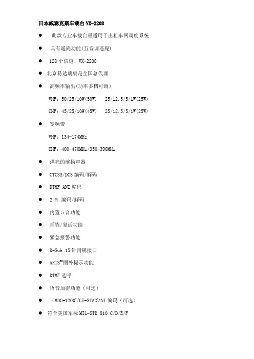
摩托罗拉-威泰克斯 VX-2208车载台彩页
- 格式:pdf
- 大小:690.70 KB
- 文档页数:2

V200S VERIS Verabar® (Single Rod) Installation and Maintenance Manual169-EN Please read and savethese instructionsContentsGeneral Safety Information (3)Product Information (3)Section 1: Scope (3)Section 2: Receiving and InspectingSection 3: Safety Precautions (3)Section 4: Installation Preparations ......................................................3-5Location (3)Orientation (4)Horizontal Piping (4)Vertical Piping (5)DP Transmitter/Local Indicator Location (5)Installation Drawings and Bill of Materials (5)Piping Support (5)Section 5: Installation Procedure .........................................................6-9Assemble the Verabar® (6)Insert Instrument Vales or Manifold (6)Valves (6)Manifold (6)Retract Sensor and Tighten Packing (7)Weld Thread-o-let to Pipe (7)Install Close Nipple & Access Valve (7)Drill Hole in Pipe (7)Mount Sensor Assembly to Access Valve (8)Vent Access Valve to Verify No Leaks are Present (8)Grease Drive Rod (8)Insert Verabar® Sensor Assembly (8)Orientation of Flow Arrow (9)Section 6: Proper Installation (10)Section 7: Periodic Maintenance (10)Limited Warranty and Remedy (11)2Designs, materials, weights and performance ratings are approximate and subject to change without notice.Visit armstrong for up-to-date information.3Designs, materials, weights and performance ratings are approximate and subject to change without notice.Visit armstrong for up-to-date information.Section 1 ScopeThese instructions provide a description of procedures for installing the V200S (Single Rod) Verabar ® flow sensor. Procedures are given for all industrial flow measurement applications including liquid, steam and gas for both horizontal and vertical piping configurations.Section 2 Receiving InspectionThe following tasks should be performed as part of the receiving inspection procedure:• Check items received against the packing list.• Check sensor nameplate for proper model number, serial number and tag number.• Verify the actual pipe diameter matches the ID stated on the sensor nameplate.• Check the bullet shaped sensor tube for any signs of damage. Damage to the sensor tube may result in erroneous flow readings.• Check the round cover tube for any damage, especially axial gouges or scratches. Damage to the cover tube may prevent the packing from sealing properly.Section 3 Safety PrecautionsThe following process should be conducted prior to installing the Verabar ® flow sensor:• Check the maximum operating conditions on the flow sensor nameplate. If any pressure, temperature or flow limits will be exceeded, contact the factory before proceeding.Section 4 Installation Preparations4.1 LocationFor the most accurate flow measurement, a minimum straight run of pipe is required. Table 1 shows the minimum straight run requirements. If longer straight runs are available, position the Verabar ® such that the ratio of upstream straight run to downstream straight run is approximately 4 to 1. If straight run lengths are less than the values stated in Table 1, contact Armstrong’s VERIS Flow Measurement Group directly. Straightening vanes should be positioned such that the end closest to the Verabar ® is half way between the Verabar ® and the closest upstream configuration. For elbow installations, mount the Verabar ® in the same planeas the closest upstream elbow.General Safety InformationProduct InformationInstructions and procedures listed in this manual may require special precautions to ensure the safety of the individuals performing the operations. Review the entire manual, taking note of safety messages prior to performing any operations listed in the manual.The VERIS Verabar ® averaging pitot flow sensor provides unsurpassed accuracy and reliability. With its solid, one-piece construction and bullet shape the VERIS Verabar ® makes flow measurement reliable and precise.The unique sensor shape reduces drag and flow induced vibration. The location of the low-pressure ports eliminates the potential for clogging and improves signal stability.The V200S model can be inserted and removed from service under pressure. It features a single drive rod and threaded mounting components.4Designs, materials, weights and performance ratings are approximate and subject to change without notice.Visit armstrong for up-to-date information.Table 1. Straight Run Requirements4.2 OrientationVerify the proper sensor orientation by checking for an “-H” (horizontal piping) or a “-V” (vertical piping) in the model number on the Verabar ® name plate. Verify that the flow arrow stamped on the instrument head is pointing downstream in the direction of flow.4.2.1 Horizontal PipingFor air or gas installations, mount the Verabar ® in the upper 160° of the pipe to allow any condensate to draininto the pipe (Figure 1). For liquid or steam installations, mount the Verabar ® in the lower 160° of the pipe. Thisallows any entrained air to bleed back into the pipe for liquid applications and allows condensate to collect in theinstrument piping for steam applications.5Designs, materials, weights and performance ratings are approximate and subject to change without notice.Visit armstrong for up-to-date information.Figure 1. Verabar ® Orientation in Horizontal Pipe4.2.2 Vertical PipingThe Verabar ® may be mounted in any location around the circumference of the pipe for vertical piping applications.4.3 DP Transmitter/Local Indicator LocationWhen choosing a Verabar ® location, consider the DP transmitter/local indicator location:• The transmitter must be mounted below the Verabar ® for liquid and steam applications.• The transmitter must be mounted above the Verabar ® for air and gas applications.4.4 Installation Drawings and Bill of MaterialsAdditional information is available in the Installation Drawings and Bill of Materials VB-7061. (Contact factory foraccess information). It contains standard and alternate transmitter locations and a complete bill of materials based on the fluid type and sensor orientation on the pipe.4.5 Piping SupportFor sensors that extend more than 36” (915mm) beyond the pipe wall or for sensors mounted in thin-walled pipes, external support of the Verabar ® is recommended. This will reduce stresses on the pipe wall.6Designs, materials, weights and performance ratings are approximate and subject to change without notice.Visit armstrong for up-to-date information.Figure 3. Access NippleSection 5 Installation Procedure5.1 Assemble The Verabar ®Your Verabar ® is shipped loosely assembled and is not properly tightened for proper pressure retention. Follow all assembly steps to ensure a safe installation (see Figure 2).5.2 Insert Instrument Vales or Manifold5.2.1 Valves• If the Verabar ® does not have a valve head, install instrument valves using proper thread sealant. Be sureinstrument shut-off valves are installed and shut prior to re-pressurizing the pipe.5.2.2 Manifold• If the Verabar ® has a direct or integral manifold, be sure the high and low pressure block valves are shutoff prior to re-pressurizing the pipe.Figure 2. Verabar ® Model V200S (Single Rod)Instrument HeadHot Tap Drilling Mechanism (Not Supplied)Thread-o-let Close Nipple Sensor Plate Cover TubeSensorPacking Bolts Packing Gland Access Nipple Stop Nut Drive RodJam NutDrive NutBushingBushingPacking GlandNippleAccess NippleCover Tube7Designs, materials, weights and performance ratings are approximate and subject to change without notice.Visit armstrong for up-to-date information.5.3 Retract Sensor and Tighten Packing• Retract the Verabar ® such that the tip of the sensor is flush with the end of the access nipple (Figure 3). Tighten the three packing bolts on the packing gland.5.4 Weld Thread-o-let to Pipe• Mark the location where the Verabar ® is to be mounted. Position the Thread-o-let over the center of the mark. Using the appropriate weld gap (1/16” [1.5mm] typical), tack weld the Thread-o-let into position. Protect threads on the Thread-o-let, then finish welding the Thread-o-let to the pipe per applicable codes.5.5 Install Close Nipple & Access Valve• Using the appropriate pipe thread sealant, install close nipple and access valve. Orient the valve (Figure 4) such that for horizontal pipes the valve handle is in-line (perpendicular for vertical pipes) with the centerline of the pipe. Be sure the valve handle does not hit the pipe during opening and closing of the valve. Verify that the close nipple and access valve are properly tightened, because beyond this point, they will not be serviceable without depressurizing the line.Figure 4. Weld Gap5.6 Drill Hole in Pipe• With the access valve in the full open position, install an appropriate Hot Tap Drilling Machine (Figure 5) and drill a hole in the pipe (hole sizes per chart below). Follow the instructions given by the Hot Tap Drilling Machine.• After the hole is completely drilled, retract the Hot Tap Drilling Machine. Shut off the access valve prior to removal of theHot Tap Drilling Machine.Access ValveClose NippleThread-o-let Gap (1/16” [1.55mm] Typical)Tack weldProtect threads Complete weldFigure 5. Hot Tap Drilling Machines5.7 Mount Sensor Assembly to Access ValveApply appropriate thread sealant to the access nipple and thread the access nipple into the access valve. Orient thesensor such that the arrow labeled “FLOW” on the instrument head is in the direction of the flow in the pipe within 3°(orientation per Figure 6).5.8 Vent Access Valve to Verify No Leaks are PresentWith the instrument valves shut, slowly crack open the access valve and verify that there are no process fluid leaks. Ifleaks are present, shut off the access valve and tighten the leaky joint.5.9 Grease Drive Rod• High temperature grease has been applied to the threaded rod at the factory. Verify the threaded rod is adequatelygreased prior to inserting the sensor. If necessary, smear grease on the threaded drive rod. A high temperaturegrease should be used on all steam applications and for temperatures above 200°F.• Grease should be applied prior to subsequent insertions and retractions.5.10 Insert Verabar® Sensor AssemblyWarning: The flow rate must be decreased to the maximum insertion/withdrawn DP/flow limit stated on theVerabar® nameplate.• The Verabar® should be oriented such that the arrow on the head is pointing in the direction of the flow.• Completely open the access valve. Then, using the drive nut, insert the sensor.• The tip of the sensor should completely bottom on the opposite end of the pipe. Continue to insert the sensor untilfirm resistance is met. This will occur when the sensor plate is approximately 2” [51mm] from the top of the packinggland.• Thread the jam nut toward the threaded bushing. The jam nut should press tightly against the threaded bushing. Thiswill lock the drive rod in place and maintain the sensor position in the pipe.8Designs, materials, weights and performance ratings are approximate and subject to change without notice.Visit armstrong for up-to-date information.9Designs, materials, weights and performance ratings are approximate and subject to change without notice.Visit armstrong for up-to-date information.Figure 6. Orientation of Flow ArrowVertical Pipe OrientationsHorizontal Pipe OrientationsDirection of Flowof FlowDirection of Flow10Designs, materials, weights and performance ratings are approximate and subject to change without notice.Visit armstrong for up-to-date information.Section 6 Periodic MaintenanceThe assembly should be periodically checked. Verify that no leaks are present. The jam nut and packing bolts shouldbe tight.Section 7 Sensor Removal Procedure• Shut off instrument valves• Reduce flow rate below the maximum insertion/withdrawn DP/flow limit stated on the Verabar ® nameplate.• Loosen jam nut.• Using the drive nut, retract the sensor until the stop nut and jam nut are pressing against the threaded bushing. • Completely shut off the access valve. Slowly crack open one of the Verabar ® instrument valves and bleed off anyremaining pressure contained in the access nipple. The sensor assembly can now be removed.Verabar ® is now properly installed (Figure 7)Instrument Head Sensor PlateAccess ValvePacking BoltsPacking GlandAccess NippleThread-o-letClose NippleStop NutThreaded Drive RodJam Nut Drive NutThreaded BushingSensor Bushing Cover TubeSensorFigure 7. Installed V200S (Single Rod)11Designs, materials, weights and performance ratings are approximate and subject to change without notice.Visit armstrong for up-to-date information.VERIS, Inc. (“VERIS”) warrants to the original user of those products supplied by it and used in the service and in the manner for which they are intended shall be free from defects in material and workmanship for a period of five (5) years from the date of installation, but not longer than 63 months from the date of shipment from the VERIS factory, unless a Special Warranty Period applies, as noted below. This warranty does not extend to any product that has been subject to misuse, neglect or alteration after shipment from the VERIS factory. Except as may be expressly provided in a written agreement between VERIS and the user, which is signed by both parties, VERIS DOES NOT MAKE ANY OTHER REPRESENTATIONS OR WARRANTIES, EXPRESS OR IMPLIED, INCLUDING, BUT NOT LIMITED TO, ANY IMPLIED WARRANTY OF MERCHANTABILITY OR ANY IMPLIED WARRANTY OF FITNESS FOR A PARTICULAR PURPOSE. The sole and exclusive remedy with respect to the above limited warranty or with respect to any other claim relating to the products or to defects or any condition or use of the products supplied by VERIS, however caused, and whether such claim is based upon warranty, contract, negligence, strict liability, or any other basis or theory, is limited to VERIS’ repair or replacement of the part or product, or, at VERIS’ option, to repayment of the purchase price. In addition to replacing any part of parts found to VERIS’ satisfaction to be defective, VERIS will pay the cost of shipment of both the defective part to the VERIS plant and the replacement part to the original user. As a condition of enforcing any rights or remedies relating to VERIS products, notice of any warranty or other claim relating to the products must be given in writing to VERIS: (i) within 30 days of last day of the applicable warranty period, or (ii) within 30 days of the date of the manifestation of the condition or occurrence giving rise to the claim, whichever is earlier. IN NO EVENT SHALL VERIS BE LIABLE FOR SPECIAL, DIRECT, INDIRECT, INCIDENTAL OR CONSEQUENTIAL DAMAGES, INCLUDING, BUT NOT LIMITED TO, LOSS OF USE OR PROFITS OR INTERRUPTION OF BUSINESS. The Limited Warranty and Remedy terms herein apply notwithstanding any contrary terms in any purchase order or form submitted or issued by any user, purchaser, or third party and all such contrary terms shall be deemed rejected by VERIS.Special Warranty Periods are as follows:Electronic components, including without limitation, differential pressure transmitters, multivariable transmitters, flow computers, rate or totalizer displays: one (1) year from the date of installation, but not longer than 15 months from the date of shipment from the VERIS factory.VERIS, Inc.Limited Warranty and RemedyArmstrong International - VERIS Flow Measurement Group5820 Glacier Way, Frederick, CO 80205 - USA Phone: 303-652-8550 Fax: 303-652-8552armstrong 169-ENPrinted in U.S.A. - 3/11/16© 2016 Armstrong International, Inc.Designs, materials, weights and performance ratings are approximate and subject to change without notice.Visit armstrong for up-to-date information.V200S VERIS Verabar ® (Single Rod)Installation and Maintenance Manual。


22081000 - 2000 MHz / 8000 Watts PeakStock No. 2208D.S. Rev. 1.4 / 08-28-2019The 2208 is a pulsed L band high-power solid-state power amplifier system suitable for octave bandwidth applications. This amplifier utilizes high power GaN devices that provide wide frequency response, high gain, high peak power capability, and low distortion. Exceptional performance, long-term reliability and high efficiency are achieved by employing advanced broadband RF matching networks and combining techniques, EMI/RFI filters, fast input and output detectors and built-in DDC with exceptional VSWR protection. The amplifier architecture is based on Empowers proprietary scalable technology and consists of a 3RU controller with power supply and four 3RU RF power blocks and is air-cooled. In addition to scalability, this amplifier is inherently rugged due to a design that virtually eliminates every internal connector found in the typical RF/Microwave system amplifier.With a proprietary scalable architecture this amplifier can be split into two separate 4KW 2207’s with the purchase of only one 3U controller and the optional accessory kit. More commonly you would start with the scalable 2206 or 2207 and add only 3U power blocks and combiner to create a 2208 when your future power requirements increase.The amplifier comes standard with Manual Gain Control (MGC). The amplifier can be controlled via the LCD touch screen, peer to peer PC connection, or through LAN for remote monitoring, control, and diagnostics. The user GUI is easy to navigate and is accessed simply through your web browser with no software to install. The control system core runs an embedded OS (Linux) and has a built-in non-volatile memory for storing multiple user configurations.▪ Blanking Input▪ Solid-state GaN design ▪ Compact Modular design▪ High Reliability and Ruggedness▪ A Member of our Pulsed Scalable Family - 2206, 2207, 2208 (Call factory to learn more)ELECTRICAL SPECIFICATIONS over temperature conditions (-10 to +40ºC)Min Typ Max UnitOperating Frequency, Instantaneous bandwidth BW 1000 2000 MHzPower Output PeakP PK 8000 Watt Pulse Width @ Duty Cycle 10% Max. P WIDTH 5.0 50 uS Duty Cycle DC 0.1 10 % Pulse Repetition Rate PRF 25 kHz Power Droop over 50μS pulse width P DROOP 0.5 dB Modulated Pulse Rise/Fall Time (10% to 90%) T R /T F 70/70 nS Input Power for Rated P PK P IN 0 dBm Input Power Range P IN -5.0 +5.0 dBm Power Gain @ Rated P PK G P 69 dB Gain Adjustment Range VVA 20 dB Gain Flatness ∆G ±2.5 / ±1.0 dB Gain Stability/24HR G STABILITY ±0.25 dB Input Return Loss S 11 -10 dBNPO – Noise Power Output Enabled -10dBm/MHzDisabled -110Delay Delay 400 nS Spurious Signals Spur -60 dBc Operating Voltage – (single-phase, 47-63Hz) V AC 180 260 Volt Power Consumption @ P OUT = 8KW PK(10% Duty Cycle) P D 4000 VA2208 1000 - 2000 MHz / 8000 Watts Peak MECHANICAL SPECIFICATIONSDimensions W x H x D(Excluding Brackets, Handles and Connectors) 17.5 x 26.25 x 27.05 x 3RUInchWeight 320 Pound RF Connectors Input/Output (Rear Panel) Input Type-N Female. Output Type-7/16 Female - Blanking Input Type-BNC, Female - Cooling Built-in, forced air cooling system, front to rear - ENVIRONMENTAL CHARACTERISTICS:Operating Ambient Temperature T A -10 +40 °C Non-operating Temperature T STG-40 +85 °C Relative Humidity (non-condensing) RH 95 %Altitude OperatingALT10,000Feet Non-operating 40,000Shock / Vibration - MIL-STD-810FShock Method 516.5, Vibration Method 514.5 SH / VIIn accordancewithPROTECTIONS:Input Overdrive +10 dBm Max.VSWR protection @ P OUT = 8000W PK At 3:1 – PA backs-off peak output power to a safe operating level – no system shutdown, “On Air” time is maximized-Thermal – Graceful Degradation Ambient +75ºC, Automatic Recovery Min. Duty Cycle Limit 12% Max. Default Data Recovery Factory Default Calibration RecoveryCOMMUNICATION INTERFACES:Ethernet Network management of device / web interface RJ45USB Mass storage / Expansion Bus USB 1.x/2.0 compatible Available OptionsAvailable optional accessory kit to scale down output power capability is required for;- SKU 2206, 2kW- SKU 2207, 4kWContact factory for details at *******************Standard Features:-180-260VAC, Single Phase-LCD Control, Ethernet-Type N Female Input & 7/16-DIN Female Output-Rear SMA Sample Ports, Forward & Reverse-BNC Female Blanking/Gating Port2208 1000 - 2000 MHz / 8000 Watts Peak316 W. Florence Ave. Inglewood, CA 90301Ph. 1 (310) 412-8100Fax. 1 (310) 412-9232 Stock No. 2208D.S. Rev. 1.4 / 08-28-20195 μS pulse width and 10% duty cycle Rise Time/Fall Time: 178nS/43nS 20 μS pulse width and 10% duty cycle Rise Time/Fall Time: 48.6nS/41.1nS 50 μS pulse width and 10% duty cycle Rise Time/Fall Time: 47.0nS/40.3nS。
