C+T 气动执行器样本-中文09版
- 格式:pdf
- 大小:2.14 MB
- 文档页数:20
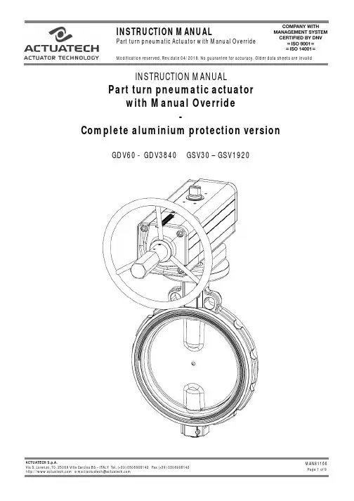
INSTRUCTION MANUALPart turn pneumatic actuatorwith Manual Override-Complete aluminium protection versionGDV60 - GDV3840 GSV30 – GSV19201)GENERAL FEATURES………………………………………………………………………………………………..pg.32)DATASHEET……………………………………………………………………………………………..pg.43)FUNCTIONAL DESCRIPTION……………………………………………..………….…………………….……………pg.54)DANGERS……….………………………………………………………………………………………..pg.75)PART DESCRIPTION……………..………………………………………………………….………………….pg.86)TRUOBLESHOOTING ………………………………………..…………………...…………………….pg.97)DISPOSAL…….………………...………………………………………………………..…………….....pg.9Environmentally friendly handling of the product.1)GENERAL FEATURES ••••••••••••••••••••••••••••••••••••••••••••••••••••••••••••••••••••••••••••••••••••••••••••••••••Actuatech manufacture a manual handwheel override for a wide range of part turn pneumatic actuators.The actuators with manual override are available on Double Acting “GDV” and Spring Return “GSV” versions.- The principle of the manual handwheel override application is to provide the possibility to open and close the valve connected to the actuator when this operation can’t be done with remote control.- Actuatech manual override actuator is itself equipped with an handwheel for manual operations and it doesn’t need any added declutchable gear box. This solution guarantees a compact size and a more light system on the valve.- When the actuator is manual operated it can be locked in Open/Closed position.- Actuator versions for low temperature and high temperature applications allow to operate respectively until temperatures of -50°C and +150°C, thanks to proper kind of lubrication and material for the gaskets.The maintenance should be done by Actuatech trained personnel only.This instruction manual contains important information regarding the Actuatech manual override actuator operation, installation, maintenance and storage.Please read carefully before installation and keep it in a safe place for further reference.Modification reserved. Rev.date 04/2018. No guarantee for accuracy. Older data sheets are invalid 2)DATASHEET•••••••••••••••••••••••••••••••••••••••••••••••••••••••••••••••••••••••••••••••••••••••••••••••••• DOUBLEACTINGNOMINALTORQUE (Nm)ISOFLANGESQUAREØHANDWEELRim pull forces ( N )To obtain thenominal torqueWeight( Kg )Teorical n° of turnsto close / openstarting from theneutral positionA B C DGDV60 60 F05-F07 14 180 19.3 2.8 11 - 99 263.3 137.6 GDV106 106 F05-F07 17 180 27.8 4 13 - 118.5 279.3 154.8 GDV120 120 F05-F07 17 180 33.8 4.5 14 - 122.1 288.4 163.9 GDV180 180 F07-F10 22 220 44.1 6 16 - 144.9 338.1 183.5 GDV240 240 F07-F10 22 220 54.5 8 18 - 156.8 353.7 199.1 GDV360 360 F07-F10 22 300 67.5 10.2 15 - 169.6 398 220.8 GDV480 480 F10-F12 27 300 83.3 13.2 16 - 193.8 440.6 236.4 GDV720 720 F10-F12 27 350 108.8 17.8 19 - 216.6 503.5 282.3GDV960 960 F10-F12 /F1436 350 128.6 23.8 20 - 239.7 518.3 297.1 GDV1440 1440 F12 / F14 36 400 133.5 33.6 25 - 283.5 636.4 365.6GDV1920 1920 F12-F16 /F1446 400 162.5 43 26 - 300.4 653.7 382.9 GDV3840 3840 F16 46 575 243.5 75 30 - 353.3 890.2 537.5SIMPLEACTINGNOMINALTORQUE (Nm)ISOFLANGESQUAREØHANDWEELRim pull forces ( N )To obtain thenominal torqueWeight( Kg )Teorical n° of turnsto close / openstarting from theneutral positionA B C DGSV30 30 F05-F07 14 180 19.3 3.2 11 129.4 - 263.3 137.6 GSV053 53 F05-F07 17 180 27.8 4.5 13 152.1 - 279.3 154.8 GSV060 60 F05-F07 17 180 33.8 4.5 14 169.3 - 288.4 163.9 GSV090 90 F07-F10 22 220 44.1 6.8 16 196.8 - 338.1 183.5 GSV120 120 F07-F10 22 220 54.5 9 18 204.8 - 353.7 199.1 GSV180 180 F07-F10 22 300 67.5 11.7 15 237 - 398 220.8 GSV240 240 F10-F12 27 300 83.3 15.2 16 260.2 - 440.6 236.4 GSV360 360 F10-F12 27 350 108.8 19.5 19 306.6 - 503.5 282.3GSV480 480 F10-F12 /F1436 350 128.6 28.1 20 324.1 - 518.3 297.1GSV720 720 F12 / F14 36 400 133.5 38.8 25 399 - 636.4 365.6GSV960 960 F12-F16 /F1446 400 162.5 50.6 26 414 - 653.7 382.9GSV1920 1920 F16 46 575 243.5 91 30 509 - 890.2 537.5 All the dimensions are in mm, for missing data see standard catalogue .Modification reserved. Rev.date 04/2018. No guarantee for accuracy. Older data sheets are invalid3) FUNCTIONAL DESCRIPTION •••••••••••••••••••••••••••••••••••••••••••••••••••••••••••••••••••••••••••••••••••••••••••••••••• NB: PRIOR TO MANUAL OVERRIDE OPERATE, ENSURE THAT THE ACTUATOR IS FREE FROM PRESSURE.1.Remove the cap to ensure there is no pressure in the actuator2.Engage the manual override and operate as required3.Disconnect the manual override (neutral position)*for standard actuators.TO CLOSE THE VALVETo close the valve turn the wheel in clockwise direction*.TO OPEN THE VALVETo open the valve turn the wheel in counterclockwise direction.* NB: Before commissioning to ensure proper disengagement, perform an ON-OFF maneuver of the actuatorModification reserved. Rev.date 04/2018. No guarantee for accuracy. Older data sheets are invalidNB: WHEN THE ACTUATOR HAS BEEN MANUALLY OPERATED, RETURN TO THE NEUTRAL POSITION PRIOR TO START NORMAL OPERATIONS.NEUTRAL POSITIONWith the screw in neutral position the piston can move freely and the actuator can be driven pneumatically. MANUAL OPERATION GDV : The handwheel turned counter clockwise, pushes the screw and piston inwards. The valve opens. GSV : The handwheel turned clockwise pushes the screw and piston inwards. The valve closes.MANUAL OPERATIONGDV : When the handwheel is turned clockwise, the screwand piston are drawn outwards. The valve closes. GSV : When the handwheel is turned counter clockwise, the screw and the piston are drawn outwards. The valve opens.Modification reserved. Rev.date 04/2018. No guarantee for accuracy. Older data sheets are invalid4)WARNINGS •••••••••••••••••••••••••••••••••••••••••••••••••••••••••••••••••••••••••••••••••••••••••••••••••• a) Don’t disassemble, compressed spring inside.b) Don’t use levers or bars.c) Don’t use the handwheel to lift the actuator.NB:Manual override is not recommended for safety related applications (SIL) as bypass of a security function. In this application, to prevent an unauthorized use, the manual override is provided with a locking device.Modification reserved. Rev.date 04/2018. No guarantee for accuracy. Older data sheets are invalid5)PART DESCRIPTION ••••••••••••••••••••••••••••••••••••••••••••••••••••••••••••••••••••••••••••••••••••••••••••••••••NB: In the case of actuator low or high temperature the pistons and the material of the O ring are different from the standard actuator.Modification reserved. Rev.date 04/2018. No guarantee for accuracy. Older data sheets are invalid6)TROUBLESHOOTING •••••••••••••••••••••••••••••••••••••••••••••••••••••••••••••••••••••••••••••••••••••••••••••••••• POTENTIAL EFFECT OFFAILUREPOTENTIAL CAUSE OF FAILURE SOLUTION Difficult manual operationsBlocked valve Repair or replace the valvePresence of particles inside the actuator due toan incorrect filtration of the airVerify the condition of the supply airand contact ActuatechThe actuator is pressurized Remove supply air7)DISPOSAL •••••••••••••••••••••••••••••••••••••••••••••••••••••••••••••••••••••••••••••••••••••••••••••••••• Our products are designed so that when they are at the end of their life cycle they can be completely disassembled, separating the different materials for the proper disposal and/or recovery. All materials have been selected in order to ensure minimal environmental impact, health and safety of personnel during their installation and maintenance, provided that, during use, they are not contaminated by hazardous substances.The personnel in charge of the product disposal/recovery, must be qualified and equipped with appropriate personal protective equipment (PPE), according to the product size and the type of service for which the device was intended. The management of waste generated during the installation, maintenance or due to the product disposal, is governed by the rules in force in the country where the product is installed, in any case, the following are general guidelines:- The metal components (aluminum/steel) can be restored as raw material;- Seals/sealing elements as contaminated by fluids from other materials and lubrication,must be disposed of.- The packaging materials that come with the product, should be transferred to the differentiated collection systemavailable in the country.。
(请务必在使用之前阅读)为了安全使用本产品▲在安装和使用之前,请务必详细阅读本说 明书,一定要注意安全,正确使用本产品, 并遵守本说明书中的各种规定。
▲基于VDE 0160。
本张力控制器是采用CPU 控制的电子设备,用来控制设备的张力, 所以要严格遵守电子设备有关规定和法则,适用标准,进行搬运安装操作和维护。
在打开控制器准备安装和接线之前要断开控制器电源至少要5分钟。
正确的配置和安装是控制器正常运行的前提。
对以下几点要特别注意:● 容许保护等级:保护接地,只有正确连接保护接地,才能减少外界电磁干扰。
●安装工作必须在无电状态下进行。
●与电网断开后,要等电容放电完毕,才可进行操作。
●不要让任何异物进入驱动器内。
●在使用前,要除去所有覆盖物,以防止装置过热。
●切勿在易燃易爆等危险环境中使用。
●请勿将本产品安装在高温、潮湿等恶劣环境下。
● 请勿将产品直接安装在易受震动冲击的环境中。
● 任何单位部门(Kortis 和Kortis 指定公司除外)未经允许不得擅自拆卸、修理、更改产品。
※注意:Kortis对由于不遵守本说明或适用规则而造成的损坏概不负责。
危险如果错误操作,将会产生危险情况,导致死亡或受重伤。
注意如果错误操作,将会产生危险情况,造成设备损坏或财产损失。
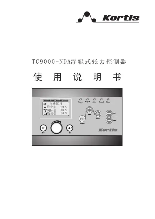
设计注意事项1.1 概述TC9000-NDA型张力控制器是一种高精度数字式可以自动控制卷材张力的自动控制仪器,它可以控制材料的放卷、送料、牵引及收卷张力。
1.2 功能及特点●采用16位高精度A/D转换器,传感器采样精度高,响应快。
●模糊PID控制,输出精度高达0.1%,张力控制更精确。
●可以直接驱动磁粉(电磁)离合器/制动器,也可控制变频、伺服等。
●可以接收传感器输入信号,自动调零,自动标定。
●人性化界面设计,操作十分方便。
●多行液晶显示,中英文菜单,编程简单,方便明了。
●内有密码功能,可以避免误操作改变设定参数。
●带有储存盒,可以将各种参数进行备份。

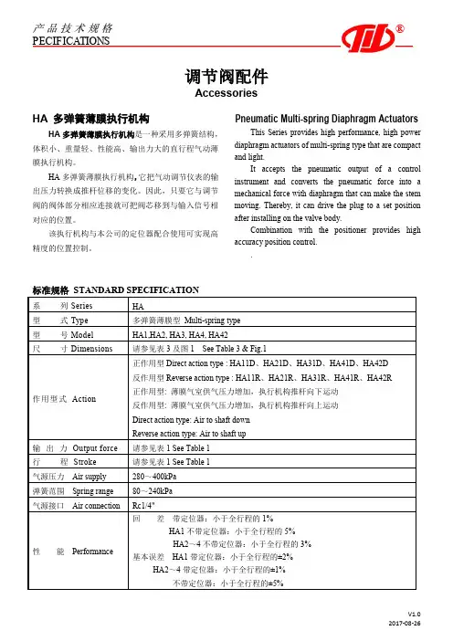
产品技术规格P E C I F I C A T I O N S®调节阀配件AccessoriesHA 多弹簧薄膜执行机构Pneumatic Multi-spring Diaphragm ActuatorsHA多弹簧薄膜执行机构是一种采用多弹簧结构,体积小、重量轻、性能高、输出力大的直行程气动薄膜执行机构。
HA多弹簧薄膜执行机构,它把气动调节仪表的输出压力转换成推杆位移的变化。
因此,只要它与调节阀的阀体部分相应连接就可把阀芯移到与输入信号相对应的位置。
该执行机构与本公司的定位器配合使用可实现高精度的位置控制。
This Series provides high performance, high power diaphragm actuators of multi-spring type that are compact and light.It accepts the pneumatic output of a control instrument and converts the pneumatic force into a mechanical force with diaphragm that can make the stem moving. Thereby, it can drive the plug to a set position after installing on the valve body.Combination with the positioner provides high accuracy position control..重庆川仪调节阀有限公司Chongqing Chuanyi Control Valve Co.,Ltd.表1 HA执行机构行程范围及输出力重庆川仪调节阀有限公司Chongqing Chuanyi Control Valve Co., Ltd.表2 手轮机构配置表3 外形尺寸及重量注:尺寸L是供气压力为零时的尺寸,括号内数字是反作用执行机构的尺寸。

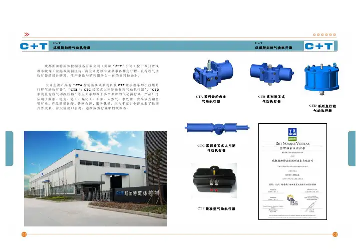
C +T 成都斯加特气动执行器 CTA 系列齿轮齿条气动执行器 成都斯加特流体控制设备有限公司(简称“C+T ”公司)位于四川省成都市蛟龙工业港双流园区内。
我公司是以专业从事各种角行程、直行程气动执行器的设计研发、生产制造与销售服务为一体的高科技企业。
公司主要产品有“CTA 齿轮齿条式系列以及CTF 紧凑型系列小扭矩角行程气动执行器”、“CTB 与CTC 拨叉式大扭矩角行程气动执行器”、“CTD 系列直行程气动执行器”等五大系列四十多个品种的气动执行器。
产品广泛应用于船舶、电力、化工、煤化工、石油、天然气、水处理、食品以及冶金等行业。
产品质量过硬、价格合理、服务优质,已与多家企业建立起了长期合作关系,并大量出口台湾,逐渐成为行业中的皎皎者。
CTB 系列拨叉式气动执行器 C +T 成都斯加特气动执行器 CTC 系列拨叉式大扭矩
气动执行器
CTD 系列直行程
气动执行器
CTF 紧凑型气动执行器。
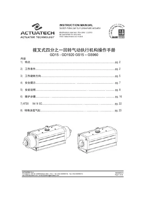
拨叉式四分之一回转气动执行机构操作手册GD15 - GD1920 GS15 – GS960内容1) 特点……………………………………………………………………………………pg.22) 工作条件………………………………………………………………………………pg.23) 工作旋转方向…………………………………………………………………………pg.54) 安全提示…………………………………………………….……………………..pg.75) 安装说明…………………………………………………..……………….……….pg.86) 维护步骤……………..…………………………………………………….……….pg.167)ATEX 94/9/EC………………………………………..……………..…………...pg.228) 特殊涂层气缸…………………………………………...…………..…………...pg.231)特点Actuatech制造生产全系列的四分之一回转气动执行机构,用以控制阀门开关动作。
产品系列有“GD”系列双作用气动执行机构,”GS”系列单作用气动执行机构。
产品具有以下特性:-通过电气连接,使得气缸在没有人力操作的情况下,开关与之相连的阀门。
-拨叉式设计是一种机械结构,这种结构能使得直线性力转化成一个旋转的扭矩。
Actuatech 正是在其产品上运用了这一机械构造。
这种结构能够在最少的能源消耗下保证设备的长效稳定工作。
-拨叉式设计的扭矩特性是在动作的起始位置提供了一个高扭矩,这一特点与阀门在开启时的高扭矩相吻合。
气缸的维护保养工作需要Actuatech的专业受训人员操作本操作手册包括了Actuatech 拨叉式气动执行机构操作、安装、维护、存储信息,请在使用产品前仔细阅读并妥善存放。
2) 工作条件_____________________________________________________________________________________a) 工作环境标准型的Actuatech气动执行机构适合于无论户内外的工作。
多回转和部分回转智能型电动阀门执行器IQ 系列RedefiningFlow Control2目录Rotork 作为全球阀门自动化及流量控制行业的领导者,我们为世界各地的组织提供最佳的产品和服务, 帮助他们提高效率、保证安全以及保护环境。
我们一直致力于技术研发、产品创新和提高质量。
因此,我们的员工和产品始终处于流体控制的最前沿。
无与伦比的可靠性是我们整个产品系列的最大特点,从我们的旗舰电动执行器产品到我们的气动、液动和电液联动执行器,以及仪表、齿轮箱和阀门配件。
Rotork 致力于为每个客户提供贯穿其工厂整个流程的一流的技术支持,从初期的现场测绘到安装、维护、检查和维修。
在我们的国内和国际办事处的网络中,我们的工程师夜以继日地工作,以更好地履行我们的职责。
Rotork . 重新定义流体控制。
章节页码章节 1 第3代IQ 执行器3 第3代执行器特性4第3代多回转执行器8 第3代部分回转执行器9先进的工程设计01设计特性21保护性及可靠性12 智能通讯14应用选项71网络总线系统81码页节章章节 2执行器规格参数 (全部内容请见 p19) 19 性能概述 20 执行器驱动连接25 标准规格参数72 阀门类型– 执行器82 设计规格92非危险 &危险区域外壳31 执行标准33 电源、控制 &显示34 保护 & 操作特性40组成部件243Redefining Flow Control近60年来,Rotork 通过不断的创新,设计了可靠、灵活且坚固的阀门执行器和控制系统。
第3代IQ 执行器的问世,不仅贯彻了我们不断发展的精神, 也同时树立了新的标杆。
更高的可靠性标准、更 简单的调试和使用,并且在提供阀门和过程控制操作数据的能力上无可匹敌。
第3代系列核心优势· 适用于所有工业区域设计基于在石油天然气、电力、水及工业行业所累积的 60余年的丰富经验。
· 性能多回转直接输出扭矩 34至 3,000* Nm 部分回转直接输出扭矩 50至 2,000 Nm直行程最大调节推力 150 kN* 如果配套额外的二级齿轮箱:多回转最大扭矩可达 43,000 Nm 角行程最大扭矩可达 1,000,000 Nm· 行业领先的可靠性能拥有坚固的传动系统 、双密封结构环境防护性能IP66/IP68(7m /72 小时)、非侵入式就地控制、固态电气元件、油浴润滑、独立的力矩 &阀位感应以及高效的机械设计· 操作安全通过Rotork 坚固而简单的绝对编码器,即使在主电源也能正常记录阀位值· 安全完整性等级 (SIL )选配的安全功能控制模块 (SFCM ) ,设计用于安全仪表系统 (SIS ) 的应用中要求功能安全完整性等级 (SIL ) 根据 IEC61508的规定达到 SIL3的场合。
PNEUMATIC CYLINDER ACTUATORSSeries BJ and B1JInstallation, Maintenance andOperating Instructions2Table of Contents1GENERAL. . . . . . . . . . . . . . . . . . . . . . . . . . . 31.1Scope of the manual. . . . . . . . . . . . . . . . . . . . 31.2Structure and operation. . . . . . . . . . . . . . . . . 31.3Actuator markings. . . . . . . . . . . . . . . . . . . . . . 31.4Specifications. . . . . . . . . . . . . . . . . . . . . . . . . . 31.5Recycling and disposal of a rejected actuator. 41.6Safety precautions. . . . . . . . . . . . . . . . . . . . . . 42TRANSPORTATION, RECEPTION ANDSTORAGE. . . . . . . . . . . . . . . . . . . . . . . . . . 53MOUNTING AND DEMOUNTING. . . . . 53.1Actuator gas supply. . . . . . . . . . . . . . . . . . . . . 53.2Mounting the actutor on the valve. . . . . . . . 53.3Operating directions. . . . . . . . . . . . . . . . . . . . 63.4Demounting the actuator from the valve. . . 64MAINTENANCE. . . . . . . . . . . . . . . . . . . . . . . . . 64.1General. . . . . . . . . . . . . . . . . . . . . . . . . . . . . . . 64.2Maintenance of the BJ actuator. . . . . . . . . . . 74.3Maintenance of the BJA actuator. . . . . . . . . . 94.4Changing the BJ actuator into a BJA actuator104.5BJR and BJAR actuators. . . . . . . . . . . . . . . . . 114.6BJV and BJK actuators. . . . . . . . . . . . . . . . . . 124.7BJVA and BJKA actuators. . . . . . . . . . . . . . . 124.8BJ 322 and BJA 322 actuators. . . . . . . . . . . 125MALFUNCTIONS. . . . . . . . . . . . . . . . . . . 136TOOLS. . . . . . . . . . . . . . . . . . . . . . . . . . . . 137ORDERING SPARE PARTS. . . . . . . . . . . 138EXPLODED VIEW AND PARTS LISTS. 148.1Actuators BJ/B1J 8-20. . . . . . . . . . . . . . . . . . 148.2Actuators BJ/B1J 25-32. . . . . . . . . . . . . . . . . 158.3Actuators BJA/B1JA 8-20. . . . . . . . . . . . . . . 168.4Actuator BJA/B1JA 25-32. . . . . . . . . . . . . . . 179DIMENSIONS AND WEIGHTS. . . . . . . . 189.1Actuators BJ/B1J, BJA/B1JA. . . . . . . . . . . . . . 189.2Actuator BJR/B1JR. . . . . . . . . . . . . . . . . . . . . 189.3Mounting face dimensions. . . . . . . . . . . . . . 1910TYPE CODING. . . . . . . . . . . . . . . . . . . . . 20READ THESE INSTRUCTIONS FIRST!These instructions provide information about safe handling and operation of the actuator.If you require additional assistance, please contact the manufacturer or manufacturer’s representative.Addresses and phone numbers are printed on the back cover.SAVE THESE INSTRUCTIONS!Subject to change without noticeAll trademarks are property of their respective owners.1GENERAL1.1Scope of the manualThese instructions provide essential information for the use of Metso Automation BJ and B1J series actuators. For more details about valves, positioners and accessories, refer to the separate installation, operating and maintenance instructions of the par-ticular unit.1.2Structure and operationThe BJ and B1J series actuators are pneumatic cylinder actuators designed for control and shut-off service.The linkage has PTFE, PE-HD and Glacier DU bearings. The robust cast-iron housing efficiently protects the mechanism from ambient dust and moisture.The spring provides the required safety function; the valve either opens or closes if the air supply is interrupted.The mounting face dimensions of the BJ actuator comply with the manufacturer ’s internal standard and those of the B1J with the ISO 5211 standard.In the BJ type, the spring is located on the piston rod side. The secondary shaft of the actuator, operated by the spring, rotates clockwise as seen from the pointer cover side. The piston then moves towards the end of the cylinder. The BJ type is normally applied for the spring-to-close operation, as it normally closes in the clockwise direction. The two keyways in the secondary shaft are positioned at an angle of 90° to each other, making it possible to change the position of the actuator in relation to the valve,see Fig. 1.In the BJA type, the spring is located in the cylinder end side. The secondary shaft, operated by the spring, rotates counter-clock-wise as seen from the pointer cover side. The piston moves away from the cylinder end. The BJA type is used for the spring-to-open function, see Fig. 1.The size of the spring actuator is selected according to the torque given by the spring. It is, however, important to check that there is sufficient supply pressure to give the required torque in the opposite direction.Screws are located in the upper end of the cylinder and in the lower end of the housing to regulate the length of the piston stroke and also the rotation angle of the actuator shaft.1.3Actuator markingsThe actuator is provided with an identification plate, see Fig. 2.Identification plate markings are:1.Type 2. PO number 3.Manufacturing date 4.Checked by 5. Max. supply pressure1.4SpecificationsAmbient temperature:Standard design-20° - + 70°CLow temperature design -40° - + 70°C High temperature design -20° - +120°C Maximum supply pressure:8.5 bar/850 kPa Stroke volume, dm 3(liters):BJ 80,9BJ 101,8BJ 123,6BJ 166,7BJ 2013BJ 2527BJ 3253BJ 322106BJBJAvalve closedvalve open2 keyways2 keywaysopening pressure closing pressurevalve closedvalve openFig. 1.Operating principle of the actuatorFig. 2.Identification plate markings3(5)(1)(2)(4)(3)Nominal torque at maximum supply pressure, Nm:BJ 870BJ 10150BJ 12300BJ 16600BJ 201200BJ 252400BJ 324800BJ 3229600NB. The torque changes according to supply pressure.1.5Recycling and disposal of a rejected actuatorMost actuator parts can be recycled if sorted according to material. Most parts have material marking. A material list is supplied with the actuator. In addition, separate recycling and disposal instructions are available from the manufacturer. An actuator can also be returned to the manufacturer for recycling and disposal against a fee.1.6Safety precautionsCAUTION:Don’t exceed the permitted values!Exceeding the permitted pressure value marked on the actuator may cause damage and lead to uncontrolled pressure release in the worst case. Damage to the equipment and personal injury may result.CAUTION:Don’t dismantle a pressurized actuator!Dismantling a pressurized actuator leads to uncontrolled pressure release. Shut off the supply pressure and release pressure from the cylinder before dismantling the actuator.Otherwise, personal injury and damage to equipment may result.CAUTION:Follow the instructions given on the actuator warning plates!CAUTION:Before opening the cylinder fastening screws,release spring tension directed on actuator warning plate and in these instructions!CAUTION:Don’t operate the actuator manually by turning from the lever arm!CAUTION:Don’t dismantle the spring package!The spring package within the cylinder is preloaded. The lock-welded fastening screw of the piston must never be opened or the spring package dismantled. The piston, piston rod, spring and spring plate of the BJ actuator are always delivered as a pre-assembled package.CAUTION:Don’t use the lever in the torsion arm for manual operation when the actuator is pressurized!Shut off the supply pressure and release pressure from the cylinder before using the hand lever. Note also the dynamic torque caused by the pipe flow.Otherwise, personal injury and damage to equipment may result.CAUTION:Take the weight of the actuator or valve combination into account when handling it!Do not lift the valve combination from the actuator,positioner or limit switch or their piping.Lift the actuator as directed in section 2,lifting ropes for a valve combination should be fastened around it.Weights are listed in the table on page 18.Dropping may result in personal injury or damage to equipment.M β / M Nβ °BJAFig. 3.Output torque a a function of turning angleM β / M Nβ °BJ42TRANSPORTATION, RECEPTION AND STORAGEMake sure that the actuator and associated equipment have not been damaged during transportation. Store the actuator carefully before installation, preferably indoors in a dry place. Do not take it to the installation site or remove the protective caps of ports for piping until just before installation.Lift the actuator as shown in Fig. 4: in a horizontal position from the stop screws, in a vertical position from an eye bolt screwed in the place of a stop screw. Do not use the lug for lifting dual-cylinder actuators. Refer to page 18 for weights.3MOUNTING AND DEMOUNTING 3.1Actuator gas supplyDry compressed air or natural gas can be used in actuators in open-close operation, no oil spraying is needed. Clean, dry and oil-free instrument air must be used for cylinder actuators with a positioner. The air supply connections are presented in the dimensional drawings on page 18. The maximum supply pressure is 8.5 bar.3.2Mounting the actutor on the valveCAUTION:Take the weight of the actuator or valve combination into account when handling it!CAUTION:Beware of the cutting movement of the valve!Install the actuator so that the shaft of the valve or any other device to be actuated goes into the shaft bore of the actuator.If the bore is larger than the shaft diameter, use a collar in between. The actuator shaft bore has two keyways at an angle of 90°. These allow the installation position of the actuator to be changed in relation to the valve. Metso Automation valves have a bevel at the end of their shafts to facilitate installation.The installation position can be selected freely, but Metso Automation recommends installation with the cylinder upright.The actuator is thus best protected against damage due to supply air impurities or water.When the installation position of the actuator is altered, the arrow indicating the operating direction must be turned to correspond with the actual operation of the valve.When necessary, lubricate the actuator bore and collar with Cortec VCI 369 or an equivalent anti-corrosive agent to prevent it from jamming due to rust.The actuator must not be allowed to come in contact with the pipework, because the vibrations may damage it or cause unsat-isfactory operation.In some cases, e.g. when using large actuators or with extensive pipework vibrations, the actuator should be supported. Consult Metso Automation for instructions.If the actuator is used with devices other than Metso Automation valves, any additional parts attached to the actuator must beproperly protected.Fig. 4.Lifting the actuatorFig. 5.Ways to install the actuator53.3Operating directions A sticker on the actuator cylinder indicates the spring action direction.NOTE:Separate instructions are available for adjusting the close limit of metal-seated butterly valves. Refer to the installation,operating and maintenance instructions of the valve.3.3.1BJ actuator -spring-to-close directionInstall the actuator on the valve with the piston in the upper end of the cylinder and the valve in the closed position, see Fig. 6.The cylinder must be depressurized and the air ports open.Adjust the closed-position setting using the stop screw (26) at the end of the cylinder. Seal the screw thread with a non-hard-ening sealant, such as Locktite 225 or the equivalent. The open-position setting is adjusted with the stop screw (27) at the bottom of the housing while the actuator is pressurized and the piston is in the lower position.3.3.2BJA actuator -spring-to-open directionInstall the actuator on the valve with the piston in the lower end of the cylinder and the valve in the open position, see fig 7. The cylinder must be unpressurized and the air ports open. Adjust the open-position setting using the stop screw (27) at the end of the cylinder. The close-position setting is adjusted with the stop screw (26) at the end of the cylinder while the actuator is pressurized and the piston is in the upper position.3.4Demounting the actuator from the valveCAUTION:Take the weight of the actuator or valve combination into account when handling it!CAUTION:Beware of the cutting movement of the valve!The actuator must be depressurized and the supply air pipes disconnected. Unscrew the actuator-side screws of the bracket and pull the actuator off the valve shaft. This is best done using a specific extractor, see fig 8 and section 6 ’Tools ’.Note the mutual positioning of the valve and the actuator to ensure correct functioning after reassembly.4MAINTENANCE 4.1GeneralCAUTION:Note the precautions in section 1.6 before beginning work!Under normal conditions, the actuators do not need regular maintenance. Maintenance procedures that the end user can do himself when necessary are described below.Unless stated otherwise, the part numbers given refer to the exploded view and parts list in section 8.In especially harsh corrosive conditions the linkage system inside the housing must be lubricated every six months. Use Cortec VCI 369 anti-corrosive agent or the equivalent. The housing may also be half filled with semi-fluid water-resistant grease (e.g.Mobilux EP2) while the piston rod is in the lower position.If you remove the stop screw, adjust the limits after lubrication or grease filling !2 keyways Closed-position stop screwOpen position stop screw80°90°Fig. 6.BJ actuator2 keyways Closed-position stop screwOpen position stop screw80°90°Fig. 7.BJA actuatorFig. 8.Removing the actuator with an extractor64.2Maintenance of the BJ actuatorCAUTION:Don ’t dismantle a pressurized actuator!CAUTION:To release spring tension, the stop screw at the end of the cylinder must be removed before the cylinder fastening screws are opened!CAUTION:Don ’t dismantle the spring package!The spring package within the cylinder is preloaded. Never open the lock-welded fastening screw of the piston or dismantle the spring package. The piston, piston rod, spring and spring plate of the BJ actuator are always delivered as a pre-assembled package.The cylinder has a warning plate (43). When servicing the unit, check that the plate is in place and legible. See Fig. 9. Also check that thecylinder has the arrow sticker indicating the spring operating direction.4.2.1Replacment of piston sealsWe recommend that all seals and soft bearings be replaced whenthe actuator has been dismantled for servicing.Detach the actuator.Check that the cylinder has been depressurized, and the piston is at the outermost end of the cylinder.Remove the cylinder end side stop screw (26).Remove cylinder end (44).Remove housing cover (2).Unscrew the bearing screw (29) and the cylinder fastening screws (31) from the cylinder base (6) side, see Fig. 10. If the piston turns, do not prevent the turning with the piston fastening nut; send the entire actuator to the manufacturer to be repaired. It is very dangerous if the lock welding of the piston fastening nut is broken!Remove the cylinder with the piston - do not dismantle the spring package!Remove the O-rings.Slide the piston out of the cylinder.Remove old seals and O-rings (24, 18).Remove piston rod seal (16) and bearing (22). Clean the seal space.Lubricate seal space and new O-ring with Unisilikon L250L or Molykote III. Install new bearing and O-ring, see fig 11.Clean piston seal groove and apply a thin coat of Cortec VCI 369.Install the O-ring (18) located under the piston seals.Place piston seals (24) around the piston so that the ends of the strips are located at opposite sides. Tighten the strips with a tie ring as in Fig. 12. Strips indicated with an asterisk can be cut 1.5 to 3 mm shorter to facilitate assembly.NOTE:The inside surface of the cylinder must be free of any grease!1824BJ 8-251824BJ 32Fig. 9. Warning plate of the BJ actuatorFig. 10.Opening the fastening screw of the actuator bearing unit(22)Press the bearing strip like this to facilitate installation(16)Fig. 11. Mounting the piston rod bearing and seal*)*)*)Fig. 12.Tightening piston seals with a tie ring7Hammer or press the piston into the cylinder through the tie ring. Note the indicator arrow direction. See Fig. 13.Install new O-rings (19). Replace cylinder end and install cylinder with piston. Note the location of the air supply port:it must correspond to the exhaust air port in the cylinder base. Tighten screws (31); the torque is given in table 1.Apply bearing unit screw (29) thread with a sealant, e.g.Locktite 225, and tighten the screw as in table 1.Fasten the housing cover temporarily so that the secon-dary shaft bearings function but the linkage can still be seen, see Fig. 14.CAUTION:Keep your fingers, tools or other items out of the housing while operating the actuator with the cover open!Check the attachment of the end and the base before temporarily connecting the compressed air supply to the actuator with a shut-off valve.Operate the actuator to check cylinder function and the condition of linkage bearings. Close the air supply and depressurize the cylinder.Lubricate the linkage throughout with Cortec VCI 369anti-corrosive agent.Apply sealant, e.g. Loctite 573, to the interface between housing and cover and fasten the cover. See table 1 for torque.Install the actuator on the valve and adjust the stop screws.To remove the cylinder base, you will need a special tool for opening the lock nut, see section 6 ’Tools ’.4.2.2Replacement of linkage bearings and O-ringsDetach actuator from valve.Check that the cylinder has been depressurized, and the piston is at the outermost end.Remove cylinder end side stop screw (26).Remove housing cover (2).Open bearing unit (5) fastening screw (29). See Fig. 10.Turn lever arm (3) to detach the bearing unit from the piston rod (10). Lift the entire linkage out of the housing.See Fig. 15.Remove lock rings (36) and support rings (37). See Fig.16.Remove connection arms (4) and check the condition of the bearings (20, 21).Torque, Nm Item 2829303135Actuator BJ 8BJ 10BJ 12BJ 16BJ 20BJ 25BJ 3290901803007001100200035901803007001100200088121220307018408080802002501501802002504008001500Table 1.Tightening torques for screwsFig. 13.Placing the piston in the cylinderFig. 14.Mounting the cover on the housing Fig. 15.Removing the linkage from the housingFig. 16.Dismantling the linkage8The connection arm (4) bearings (20, 21) of the BJ8-25 actuator are fastened with a press-on fit, and therefore the entire connec-tion arm must be replaced instead of changing the bearings. In the BJ32 actuator, the bearings can be removed.Remove lever arm bearings (23) and O-rings (17).Clean the linkage parts and apply Cortec VCI 369 to bearing and seal surfaces.Install new lever arm bearings and O-rings.Assemble the linkage and install in the housing; the correct position is shown in Fig. 15.Apply sealant, e.g. Locktite 225, to the bearing unit screw (29) thread and tighten the screw as in table 1.Lubricate the linkage throughout with Cortec VCI 369anti-corrosive agent.Apply sealant, e.g. Loctite 573, to the interface between housing and cover and fasten the cover. See table 1 for torque.Operate the actuator to check that it is moving properly.Install the actuator on the valve and adjust the stop screws.In a corrosive environment with high ambient humidity the linkage must be lubricated with Cortec VCI 369 every six months or the housing filled with grease. See section 4.1.4.3Maintenance of the BJA actuatorCAUTION:Don ’t dismantle a pressurized actuator!CAUTION:To release spring tension, always remove the stop screw at the bottom of the housing before opening the cylinder fastening screws !The cylinder has a warning plate (43), see fig 17. When servicing the unit, check that the plate is in place and legible. Also check that the cylinder has the arrow sticker indicating the spring operating direction.CAUTION:Don ’t dismantle the spring package!The spring pack within the cylinder is preloaded. Never open the lock-welded fastening screw or the piston or dismantle the spring package. The piston, piston rod, spring and spring plate of the BJA actuator are always delivered as a pre-assembled package.4.3.1Replacement of piston sealsWe recommended that all seals and soft bearings be replaced when the actuator has been dismantled for servicing.Detach the actuator from the valve.Check that the cylinder has been depressurized, and the piston is at the cylinder base end.Remove the cylinder base side stop screw (27).Remove cylinder fastening screws (31) from the cylinder base (6) side. Lift the cylinder off together with the end.Remove housing cover (2).Turn the linkage enough to expose the bearing unit fastening screw (29). Open the screw.Remove the piston with the spring package - do not dismantle the spring package!Remove old seals and the O-ring (24, 18).Remove piston rod seal (16) and bearing (22). Clean the seal space.Lubricate seal space and new O-ring with Unisilikon L250L or Molykote III. Install new bearing and O-ring, see fig 11.Clean piston seal groove and apply a thin coat of Cortec VCI 369.Install the O-ring (18) located under the piston seals.Place piston seals (24) around the piston so that the ends of the strips are at opposite sides. Tighten the strips with a tie ring as in Fig. 18. Strips indicated with an asterisk can be cut 1.5 to 3 mm shorter to facilitate assembly.NOTE:The inside surface of the cylinder must be free of any grease!Fig. 17.BJA actuator warning plateFig. 18.Tightening piston seals with the tie ring1824BJA 8-25*)1824BJA 32*)*)9Hammer or press the piston into the cylinder through the tie ring. Note the indicator arrow direction. See Fig. 19.Install new cylinder base O-rings (19). Replace cylinder with piston.Apply sealant, e.g. Locktite 225, to the bearing unit screw (29) thread and tighten the screw as in table 1 before mounting onto cylinder base.Fasten the housing cover temporarily so that the secon-dary shaft bearings function but the linkage can be seen.CAUTION:Keep your fingers, tools or other items out of the housing while operating the actuator with the cover open!Check the attachment of the end and the base before temporarily connecting the compressed air supply to the actuator with a shut-off valve.Operate the actuator to check cylinder function and the condition of bearings. Close the air supply and depressur-ize the cylinder.Lubricate the linkage throughout with Cortec VCI 369anti-corrosive agent.Apply sealant, e.g. Loctite 573, to the interface between housing and cover and fasten the cover. See table 1 for torque.To remove the cylinder base, you will need a special tool for opening the lock nut, see section 6 ’Tools ’. When reinstalling,secure the nut with Loctite 225.Install the actuator on the valve and adjust the stop screws.4.3.2Replacement of linkage bearings and O-ringsCAUTION:For reasons of safety, follow the work procedure given below exactly.Detach actuator from valve.Check that the cylinder has been depressurized, and the piston is at the cylinder base end.Remove cylinder base stop screw (27).Remove housing cover (2).Open cylinder fastening screws (31) from the base side.Lift cylinder and piston until the bearing unit fastening screw (29) can be opened.Open fastening screw. See Fig. 10.Turn lever arm (3) to detach the bearing unit (5) from the piston rod. Lift the entire linkage out of the housing. See Fig. 15.Remove lock rings (36) and support rings (37). See Fig. 16.Remove connection arms (4) and check the condition of the bearings (20, 21).The connection arm (4) bearings (20, 21) of the BJ8-25 actuator are fastened with a press-on fit, and so the entire connection arm must be replaced instead of changing the bearings. In the BJ32actuator, the bearings can be removed.Remove lever arm bearings (23) and O-rings (17).Clean linkage parts and apply Cortec VCI 369 to bearing and seal surfaces.Install new lever arm bearings and O-rings.Assemble the linkage and install in the housing.Apply sealant, e.g. Locktite 225, to bearing unit screw (29)thread and tighten the screw as in table 1.Install new cylinder base O-ring (19). Install the cylinder.Apply Cortec VCI 369 anti-corrosive agent to the linkage throughout.Apply sealant, e.g. Loctite 573t, to the interface between housing and cover, and fasten the cover.Operate the actuator to check that it is moving properly.Install the actuator on the valve and adjust the stop screws.In a corrosive environment with high ambient humidity the linkage must be lubricated with Cortec VCI 369 about every six months, or the housing filled with grease. See section 4.1.4.4Changing the BJ actuator into a BJA actuatorThe BJ actuator can be changed into a BJA actuator by replacing the spring package and turning the cylinder the other way around.4.4.1Removing the cylinderRemove the cylinder as in section 4.2.1.4.4.2Changing the spring packageReplace the spring package of the BJ actuator with a BJA spring package ordered from the manufacturer. The cylinder must be turned 180°. See Fig. 20.NOTE:The warning plate of the cylinder must also be changed tocorrespond with the BJA actuator!Fig. 19.Placing the piston in the cylinderFig. 20.Turning the cylinder104.4.3Assembling the actuatorAssemble the actuator as in section 4.3.1.4.5BJR and BJAR actuators4.5.1BJR actuatorThe BJR actuator is otherwise like the BJ except that it can be operated manually to bring the piston to the lower position against the spring in case there is no air supply. The BJ actuator can be changed into a BJR by replacing the cylinder end (44) accordingly and adding parts (50 to 56).4.5.1.1MaintenanceCAUTION:To release spring tension, always remove the threaded spindle and spindle nut at the cylinder end before opening the cylinder fastening screws!The cylinder has a warning plate (43), see fig 21. When servicing the unit, check that the plate is in place and legible. Also check that the cylinder has the arrow sticker indicating the spring operating direction.If air escapes between the spindle (50) and spindle nut (51), check the O-ring (54) and replace it if necessary. Also check the condition of the cylindrical rollers (56). See Fig. 22. Other maintenance as described for the BJ actuator in section 4.2.Parts list for Fig. 22:Part Quantity Name501Spindle511Spindle nut521Hand wheel531Lock nut541O-ring551Spring pin561Cylindrical roller4.5.1.2Valve close and open position adjust-mentIn the BJR actuator, unlike in the BJ, the upper valve position limit is adjusted with the spindle nut (51) secured with the lock nut (53). During adjusting, the spindle (50) must be in the extreme outer position.4.5.2BJAR actuatorThe BJAR actuator is otherwise like the BJA, except that it can be operated manually to bring the piston to the upper position against the spring in case there is no air supply. The BJA actuator can be changed into a BJAR by replacing the housing (1) and adding parts (50 to 56), see Fig. 24.To make the change, the actuator must be dismantled, see section 4.3.2. A special tool is needed to unscrew and fasten the lock nut (35) fastening the cylinder base to the housing. See chapter 6 ’Tools’.4.5.2.1MaintenanceCAUTION:To release spring tension, always remove the threaded spindle and spindle nut at the cylinder end before opening the cylinder fastening screws!The cylinder has a warning plate (43). When servicing the unit, check that the plate is in place and legible, see Fig. 23. Also check that the cylinder has the arrow sticker indicating the springoperating direction.If stiffness or noise occurs when the actuator is operated with thehandwheel, check the condition of the bearings (56), see Fig. 24.Other maintenance as described for the BJA actuator in section 4.3. Fig. 21.BJR actuator warning plateFig. 22.BJR actuatorFig. 23.BJAR actuator warning plate11。
Measures, Monitors and Controls For The Process IndustriesPneumatic Actuators Electric Actuators PositionersAccessories- Limit Switch Box- Declutchable Manual Override Gearbox - Air Filter Regulator- Pilot Solenoid Valve2SpecificationsThe AEJAT pneumatic rotary actuator is of rack and pinion design where the linear kinetic energy is directly transformed into a "quarter turn" operation with a constant torque output over the full stroke.Both double acting and spring return actuators have twin pistons horizontally opposed and incorporate piston guides to ensure correct contact between the rack and pinion at all pressure.High quality materials are used in the construction of the actuator. The actuator can be readily fitted to any type of ball valve, butterfly valve or other equipment requiring efficient pneumatic actuator.Full range of accessories, such as limit switch box, solenoid valve, positioner and declutchable manual override gearbox are available.DesignFunction Double Acting (DA) or Spring Return (SR)Material Housing Extruded aluminum alloy, hard anodized End Cap Pressure die cast aluminum alloy, epoxy coated Pinion Carbon steel, nickel platedPiston Cast aluminum / steel, hard anodized / Zinc galvanized Cap Screw Stainless steelSpringSpring steel, Dip Coated Bearing and Guide Engineering plastic Travel Stop Cam Alloy steel Adjustment Screw Stainless steelSealNBR (Other seal on request)Mounting Bracket Aluminum, stainless steel, alloy steel Technical Data Operating MediaDry or lubricated compressed air or non-corro-sive gases. The max particle diameter must be less than 30um Supply Pressure Min. 2 bar, Max. 8 barOperating Temperature -20o C to +80o C (NBR)Lower or higher temperature version on request Rotation90o Travel Adjustment ± 5oMounting Connection Namur, ISO5211 and DIN3337Torque Output3 Nm to 13024 Nm (DA)4 Nm to 6584 Nm (SR)FeaturesTravel adjustment range of ±5o for the rotation at 0o and 90oAir Supply connection in accordance to NAMURstandard for easy installation of pilot solenoid valve Namur drive pinion and Namur top mounting connection permit direct installation of accessories such as Limit Switch Box and PositionerBottom mounting connection in accordance to ISO5211 and DIN3337 standards for direct mounting withvalve, gear box or mounting bracketWorking PrincipleDouble ActingSpring ReturnCounter Clockwise RotationCounter Clockwise RotationClockwise RotationClockwise RotationAccessories AvailableLimit Switch Box with 2x mechanical or proximity switchesDeclutchable Manual Override for emergency ortesting operationPilot Solenoid Valve with Namur Interface3Construction and MaterialsNo.DescriptionQty Standard Material Protection Optional Material1Body 1Extruded Aluminum AlloyHard Anodized 2End Cap 2Cast Aluminum 3Shaft 1Carbon Steel Nickel PlatedStainless Steel 4Piston 2Cast Aluminum / SteelAnodized / Zinc GalvanizedStainless Steel 5Cap Screw 8Stainless Steel6O-ring (End Top)2NBR FPM / Silicone7Spring 0 - 12Spring Steel Dip Coating8Bearing 2Engineering Plastic9O-ring (Piston)2NBR10Guide 2Engineering Plastic 11Outside Washer 1Engineering Plastic 12Thrust Washer 1Stainless Steel 13Spring Clip 1Stainless Steel14Indicator 1Plastic 15Indicator Screw 1Plastic 16Inside Washer1Engineering Plastic17Cam 1Alloy Steel 18O-ring (Shaft)1NBRFPM / Silicone19Bearing (Top of Shaft)1Engineering Plastic 20Bearing (Bottom of Shaft)1Engineering Plastic21O-ring (Bottom of Shaft)1NBR FPM / Silicone 22O-ring (Adjustment Screw)2NBR FPM / Silicone23Washer 2Stainless Steel 24Nut2Stainless Steel Powder Polyester Painted25Adjustment Screw 2Stainless Steel 26Shaft Adaptor1Sintered Alloy2541067894987652131011121314151617181920212223242526Spring Positions of Spring Return ActuatorAir Consumption and Opening and Closing TimeModel AEJAT032AEJAT040AEJAT052AEJAT063AEJAT075AEJAT083AEJAT092AEJAT105AEJAT125Cylinder Air Volume (L)Open0.040.080.10.20.30.50.7 1.2 1.5 Close0.050.110.20.30.50.8 1.1 1.8 2.3Opening & Closing Time (Second)DAOpen0.10.10.20.30.30.40.50.70.9 Close0.10.10.20.30.40.50.60.8 1.1 SROpen--0.30.30.40.50.70.9 1.2 Close--0.30.40.50.60.9 1.1 1.4Model AEJAT140AEJAT160AEJAT190AEJAT210AEJAT240AEJAT270AEJAT300AEJAT350AEJAT400Cylinder Air Volume (L)Open 2.4 3.1 4.3 5.810.014.523.835.152.6 Close 3.8 4.9 6.99.515.221.429.746.369.4Opening & Closing Time (Second)DAOpen 1.2 1.5 2.0 2.7 3.5 4.08.010.010.0 Close 1.4 1.7 2.2 3.2 4.0 4.510.012.013.0 SROpen 1.5 1.8 2.4 3.5 4.1 4.57.08.08.0 Close 1.8 2.1 2.8 4.0 4.6 5.08.09.09.0ModelInput Air Supply Pressure (Bar)2345678AEJAT032DA356891112 AEJAT040DA 4.87.19.611.914.316.719.1 AEJAT052DA8.112.116.220.124.228.232.3 AEJAT063DA14.321.428.535.642.749.856.7 AEJAT075DA2030.240.350.460.470.580.6 AEJAT083DA30.946.361.877.192.5108123.5 AEJAT092DA44.266.388.4110.5133154.8176.7 AEJAT105DA65.898.8131.6164.5197.4230.4263.2 AEJAT125DA102.6153.9205.2256.5307.8359.1410.4 AEJAT140DA175.5263.2351438.7526.3614.2702.1 AEJAT160DA267.4401534.9668.8801.8935.81069.7 AEJAT190DA450.4646861.71078.312931507.71723.3 AEJAT210DA526.3789.51052.61314.81578.91842.12105.2 AEJAT240DA773.311601546.61933.32319.92706.63093.2 AEJAT270DA1174.21761.32348.42935.53522.64109.74696.8 AEJAT300DA1610.82416.23221.64027.14832.55637.96443.3 AEJAT350DA2411.83617.64823.56029.47235.38441.19647.1 AEJAT400DA325648846512814097681139613024 Double Acting Output Torque (Nm)45Single Acting Output Torque (Nm)ModelS p r i n g Q t yAir Supply PressureOutput Torque Spring 3 Bar 4 Bar5 Bar6 Bar7 Bar8 Bar0o 90o 0o 90o 0o 90o 0o 90o 0o 90o 0o 90o 0o 90o Start End Start End StartEndStartEndStartEndStartEndStart End AEJAT052SR58.87.313.011.6 5.4 4.068.0 6.312.210.516.514.8 6.5 4.778.2 5.211.59.415.713.720.017.97.6 5.58 6.44.110.78.314.912.619.216.823.421.18.6 6.399.97.314.111.518.415.822.620.026.924.39.77.1109.1 6.213.310.417.614.721.818.926.123.210.87.91112.59.416.813.621.017.925.322.111.98.71211.88.316.012.520.316.824.521.013.09.5AEJAT063SR515.712.523.120.09.9 6.8614.310.521.818.029.325.511.98.1713.08.520.416.027.923.535.431.013.99.5811.66.519.114.026.621.534.029.041.536.515.910.8917.712.025.219.532.727.040.234.547.642.017.912.21016.410.023.817.531.325.038.832.546.340.019.913.61122.515.530.023.037.530.544.938.021.914.91221.113.528.621.036.128.543.636.023.916.3AEJAT075SR527.021.639.334.015.510.2624.918.537.330.949.743.318.612.2722.915.535.327.847.640.260.052.621.714.2820.912.433.224.745.637.158.049.570.461.824.816.2931.221.643.634.056.046.468.358.780.771.127.818.31029.218.541.630.953.943.366.355.778.768.030.920.31139.527.851.940.264.352.676.664.934.022.31237.524.749.937.162.249.574.661.837.124.4AEJAT083SR533.827.250.143.421.514.9630.922.947.139.163.355.325.817.8727.918.644.134.860.451.076.667.330.120.8824.914.341.230.557.446.773.663.089.979.234.423.8938.226.254.442.470.758.786.974.9103.191.138.726.71035.221.951.538.167.754.483.970.6100.286.843.029.71148.533.864.750.181.066.397.282.547.332.71245.529.561.845.878.062.094.278.251.635.6AEJAT092SR548.039.571.362.830.321.8643.733.566.956.790.280.036.326.1739.327.462.650.785.873.9109.197.242.430.5834.921.458.244.681.567.9104.791.2128.0114.448.434.9953.838.677.161.8100.485.1123.6108.4146.9131.654.539.21049.532.572.855.896.079.0119.3102.3142.6125.660.643.61168.449.791.773.0114.996.3138.2119.566.647.91264.043.787.366.9110.690.2133.8113.572.752.3AEJAT105SR564.657.799.292.446.239.3656.748.591.483.1126.0117.855.447.2748.939.383.573.9118.2108.5152.8143.264.655.0841.030.075.764.7110.399.3144.9133.9179.6168.673.962.9967.855.4102.490.1137.1124.7171.7159.3206.3194.083.170.71059.946.294.680.8129.2115.5163.9150.1198.5184.792.378.61186.771.6121.4106.2156.0140.9190.6175.5101.686.51278.962.4113.597.0148.1131.6182.8166.3110.894.36Single Acting Output Torque (Nm)ModelS p r i n g Q t yAir Supply PressureOutput Torque Spring 3 Bar 4 Bar5 Bar6 Bar7 Bar8 Bar0o 90o 0o 90o 0o 90o 0o 90o 0o 90o 0o 90o 0o 90o Start End Start End StartEndStartEndStartEndStartEndStart End AEJAT125SR51311041921668053612088182150243211966471107217113423219529425711274899561611182221792832413453021288591501022111632732253342863953471449610139862011472622093232703853311601061119013125119331325437431517511712179115241177302238363299191127AEJAT140SR51881442802361338961701172632093553021601077152902451833372754303681871258135642271563192494123415044332131429209129302222394314486407579499240160101911032841953762884693805614722671781126616935826145135354344629319612248142341234433327525419320214AEJAT160SR52862224273622011366259182400322541463241163723214137328251342365456428119082051013452424863836275247686643212189318202459343600483741624881765361245102911624323035734437135848547254012721140526354540368654482768544129912377222518363659504800645481326AEJAT190SR5448332675559349232640226262948985671641827873561925824198096461036873488325830912353635076357699080312171030558371949028071750794373311709601397118762741810443210670437897664112489113511117697464116243678515941077821130410487675101257729780452410317511258978837557AEJAT210SR56384689507804672976579375890687120299856035675192828315931143905145512176544168460188772500108381213951123170714357574759712407102471813361030164713421959165384053510653313965625127693715881248190015609345941190553112178431529115518401467102765312846438115875014691062178113731121713AEJAT240SR59636661452115579950368625061351995184014849596037762346125083517391324222818121119704866118711506751639116421271652261621411279804910495151538100420271492251519813004247014399051094935514378441926133324151821290323101599100511133768418251173231516612803215017591106121236524172510132213150127021990191912077Single Acting Output Torque (Nm)ModelS p r i n g Q t yAir Supply PressureOutput Torque Spring 3 Bar 4 Bar5 Bar6 Bar7 Bar8 Bar0o 90o 0o 90o 0o 90o 0o 90o 0o 90o 0o 90o 0o 90o Start End Start End StartEndStartEndStartEndStartEndStart End AEJAT270SR5143110282118171510336306130582119921508267921951240765711796151866130225531989324026761446882810534081740109524271782311424693801315616531008916148892301157629882263367529504363363718601134101488682217513692862205635492743423734302066126011204911622736184934232536411132232273138612192395626101643329723303985301724801512AEJAT300SR613168751273876711536391916140214851022899140317541166251719291697116891592930235516933118245619091314101430695219314582956222137192984448237472122146011203012222793198535562748431935112334160612186898626311749339425124157327525461752AEJAT350SR61863115720431408716027792745192223831642813414012484154436262686272418779222411653336230745083449306421121019637873105192942473071539042146532535634052346112844155139862693512938366271497837452581122584117237262314486934576011459940862816AEJAT400SR825501225329221009225976838872396370323621019673113595193952233567411526241133031482493131106559473845262887123012102546402653626842817895590895237536493831491343482195597638237603545092317078534934121440571738568533667312499389406621576136741537651281539329097020453686486164617239371651012452672840798356570765844199Dimension (mm)Model A B C D E F G H I J K L M NØO P AirSupply Weight (kg)AEJAT032DA9011223.523.5452612F03-4-M5x8-9x950303420G1/80.55 SR-AEJAT040DA9312323.533602612F03F054-M5x84-M6x1011x1150303420G1/80.66 SR-AEJAT052DA1081453041722615F03F054-M5x84-M6x1011x1180303420G1/41.2 SR 1.3AEJAT063DA1251694646892615F05F074-M6x104-M8x1214x1480303420G1/41.9 SR2.1AEJAT075DA12820142521002615F05F074-M6x104-M8x1214x1480303420G1/42.8 SR3.1AEJAT083DA14720946551092615F05F074-M6x104-M8x1214x1480303420G1/43.2 SR 3.7AEJAT092DA1682425157.51172620F05F074-M6x104-M8x1217x1780304120G1/44.6 SR5.2AEJAT105DA18627558641342625F07F104-M8x124-M10x1622x2280304120G1/46.1 SR7.1AEJAT125DA20733267.5701573625F07F104-M8x124-M10x1622x2280306230G1/49.5 SR10.9AEJAT140DA26840076771743630F10F124-M10x164-M12x2027x27130306230G1/413.7 SR15.7AEJAT160DA30845587.587.51993830F10F124-M10x164-M12x2027x27130306230G1/420.5 SR23.6AEJAT190DA3905071031032323840-F12-4-M12x2036x36130307930G1/431.1 SR35.3AEJAT210DA3905621131132573840-F12-4-M12x2036x36130307930G1/441.8 SR46.6AEJAT240DA4306461291292933852-F16-4-M20x2446x46130307930G1/462.4 SR72.4AEJAT270DA5107221461463333852-F16-4-M20x2446x46130307930G1/486.3 SR98.3AEJAT300DA5798251621733543852-F16-4-M20x2446x46130307930G1/2103 SR143AEJAT350DA5808661901954103852-F16-4-M20x2446x46130307930G1/2144 SR188AEJAT400DA-9242582584643860-F25-8-M16X2455X55130307930G1/2289 SR3608Singapore OfficeAnderson Eurotech Singapore Pte Ltd1, Yishun Industrial Street 1, #08-05,A’Posh BizHub, Singapore 768160+65 66944233**************************The specifications given in this document represent the state of engineering at the time of publishing. We reserve the right to make modifications to the specification and materials。
Pneumatic rotary actuatorDouble acting and spring return The 2051QT pneumatic rotary actuators are ofthe rack and pinion type where the linear kineticenergy is directly transformed into a “quarter turn” operation with a constant output torque over the full stroke.Both double acting and spring return actuators have twin pistons horizontally opposed and incorporate piston guides to ensure correct contact between the rack and pinion at all pressures.High quality materials are employed throughout the construction and the compact design is readily fitted to any type of ball valve, butterfly valve or other equipment requiring efficient pneumatic actuators.The actuator is suitable for mounting a full range of accessories, such as limit switches, solenoid valves, positioners and manual override gearbox.Extruded aluminium alloy, gold anodizedPressure die cast aluminium alloy, black epoxy coated Carbon steel, zinc platedType 6519NAMUR Solenoid valve Type 8792/93 Positioner SideControlType MV2650Ball valve Type 1062QTPosition feedbackType VV2670Butterfly valveFunctional principleDouble acting actuator (DA)Counter clockwise output operation is achieved by inserting pressure into Port ‘A’, to force piston apart thus rotating the actuator pinion counter clockwise. During the operation, air from the outer chambers is exhausted through Port ‘B’. Clockwise output operation is achieved by reverse of the above and inserting pressure into Port ‘B’.Single acting actuator (SR)Pressure applied to Port ‘A’ will cause the inner chambers to be pressurized, forcing the pistons outward to compress the springs. The pinion is rotated counter clockwise. Upon release of pressure through Port ‘A’ the springs will exert pressure to close the pistons and rotate the pinion clockwise rapidly. This action will often be used to close a 90oturn valve in shutdown mode.Pistons assembly variationsArrangement of springs for single acting actuatorActuator direction of rotation can be changed by switching both the pistons in accordance to the below diagramSprings can be added or removed according to torque requirement. It is recommended to install springs in accordance to the below diagramAir ConsumptionFree Air per stroke (Liters)Opening / Closing timeat 5.6 bar airWeight (kg)Torque Output (Nm) | Ordering Chart (other versions on request) Double acting actuator (DA)Torque Output (Nm) | Ordering Chart (other versions on request) Single acting actuator (SR)Dimensions [mm]AP01 to AP10 DA/ SR*** To be specified during order. Please refer to Ordering Chart.Parts listAP01 to AP10 DA/ SR* Suggested spare parts for routine maintenanceDimensions [mm]AP00 DAParts listAP00 DA* Suggested spare parts for routinemaintenanceDimensions [mm] - with accessoriesIn case of special application conditions,please consult for advice.We reserve the right to make technical changes without notice2051QT/EN/R1_12/2013With Type 6519 NAMUR solenoid valveWith declutchable manual override gearboxWith 879x positioner SideControlWith 1062QT position feedback。