q1-1汽车使用条件
- 格式:pdf
- 大小:249.77 KB
- 文档页数:45

《热力学第一定律应用举例》讲义一、热力学第一定律简介热力学第一定律,也称为能量守恒定律,是热力学的基本定律之一。
它表明,在一个封闭系统中,能量可以在不同形式之间转换,但总能量保持不变。
简单来说,就是输入系统的能量等于系统输出的能量与系统内部能量变化的总和。
这个定律的数学表达式为:ΔU = Q W ,其中ΔU 表示系统内能的变化,Q 表示系统吸收的热量,W 表示系统对外所做的功。
二、热力学第一定律的应用领域热力学第一定律在许多领域都有着广泛的应用,以下是一些常见的例子:1、热机热机是将热能转化为机械能的装置,如蒸汽机、内燃机和燃气轮机等。
在热机的工作过程中,燃料燃烧产生的热能被输入到系统中,一部分热能通过做功转化为机械能输出,另一部分则以废热的形式排放到环境中。
根据热力学第一定律,输入热机的热能等于输出的机械能与排放的废热之和。
通过对热机效率的研究,可以不断改进热机的设计,提高能源的利用效率。
2、制冷与空调系统制冷和空调系统的工作原理是通过消耗外界的功或电能,将热量从低温物体转移到高温物体。
在这个过程中,系统吸收低温物体的热量Q1,同时向高温环境排放热量 Q2,并且消耗外界的功 W 。
根据热力学第一定律,Q2 = Q1 + W 。
通过对制冷和空调系统的性能分析,可以优化系统的运行参数,降低能耗,提高制冷和空调效果。
3、化学反应在化学反应中,往往伴随着能量的吸收或释放。
例如,燃烧反应会释放大量的热能,而一些吸热反应则需要从外界吸收热量才能进行。
通过对化学反应中能量变化的研究,可以预测反应的热效应,为化学工艺的设计和优化提供依据。
4、能源储存与转换随着可再生能源的发展,如太阳能和风能,能源的储存和转换成为了重要的研究课题。
例如,在电池中,电能和化学能之间的相互转换遵循热力学第一定律。
在太阳能热水器中,太阳能被转化为热能储存起来。
通过对能源储存和转换过程的分析,可以提高能源的利用效率和稳定性。
三、具体应用举例1、汽车发动机汽车发动机是一个典型的热机。
ICS13.020.40Z 60 DB37 山东省地方标准DB37/ 2801.1—2016挥发性有机物排放标准第1部分:汽车制造业Emission standard of volatile organic compounds ——Part 1:Automobile manufacturing industry2016-07-06发布2017-01-01实施山东省环境保护厅目次前言 (II)1 范围 (1)2 规范性引用文件 (1)3 术语和定义 (1)4 挥发性有机物排放控制要求 (3)5 监测要求 (5)6 实施与监督 (5)附录A(规范性附录)确定某排气筒最高允许排放速率的外推法 (7)附录B(规范性附录)等效排气筒有关参数计算方法 (8)附录C(规范性附录)单位涂装面积挥发性有机物排放总量核算 (9)前言DB37/ 2801 《挥发性有机物排放标准》已经或计划发布以下部分:——第1部分:汽车制造业;第2部分:铝型材工业;第3部分:家具制造业;第4部分:印刷业。
本部分为DB37/ 2801的第1部分。
本部分规定了山东省汽车制造业挥发性有机物排放控制和监测要求,以及标准的实施与监督等有关要求。
山东省汽车制造业排放水污染物、除挥发性有机物外的其他大气污染物、恶臭污染物、环境噪声适用相应的国家和地方标准,产生固体废物的鉴别、处理和处置适用相应的国家固体废物污染控制标准。
本部分按照GB/T 1.1—2009给出的规则起草。
本部分由山东省环境保护厅提出。
本部分由山东省环境保护标准化专业技术委员会归口。
本部分起草单位:山东省环境规划研究院、济南市环境保护规划设计研究院、济南颐华环保有限公司。
本部分主要起草人:史会剑、谢刚、马召坤、袁琦、吴彤、赵红、胡欣欣、李玄、孙辉。
挥发性有机物排放标准第1部分:汽车制造业1 范围本标准规定了山东省汽车制造业挥发性有机物排放控制和监测要求,以及标准的实施与监督等有关规定。
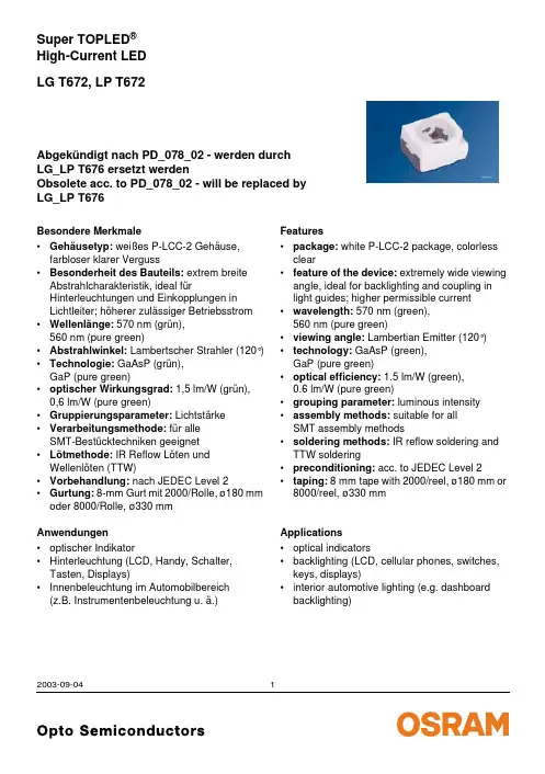
LG T672, LP T672Super TOPLED ®High-Current LED Abgek ündigt nach PD_078_02 - werden durch LG_LP T676 ersetzt werdenObsolete acc. to PD_078_02 - will be replaced by LG_LP T6762003-09-041Besondere Merkmale•Geh äusetyp: wei ßes P-LCC-2 Geh äuse, farbloser klarer Verguss•Besonderheit des Bauteils: extrem breite Abstrahlcharakteristik, ideal f ürHinterleuchtungen und Einkopplungen in Lichtleiter; h öherer zul ässiger Betriebsstrom •Wellenl änge: 570 nm (gr ün), 560nm (pure green)•Abstrahlwinkel: Lambertscher Strahler (120°)•Technologie: GaAsP (gr ün), GaP (pure green)•optischer Wirkungsgrad: 1,5lm/W (gr ün), 0,6lm/W (pure green)•Gruppierungsparameter: Lichtst ärke •Verarbeitungsmethode: f ür alle SMT-Best ücktechniken geeignet •L ötmethode: IR Reflow L öten und Wellenl öten (TTW)•Vorbehandlung: nach JEDEC Level 2•Gurtung: 8-mm Gurt mit 2000/Rolle, ø180 mm oder 8000/Rolle, ø330 mm Anwendungen•optischer Indikator•Hinterleuchtung (LCD, Handy, Schalter, Tasten, Displays)•Innenbeleuchtung im Automobilbereich (z.B.Instrumentenbeleuchtung u. ä.)Features•package: white P-LCC-2 package, colorless clear•feature of the device: extremely wide viewing angle, ideal for backlighting and coupling in light guides; higher permissible current •wavelength: 570nm (green), 560nm (pure green)•viewing angle: Lambertian Emitter (120°)•technology: GaAsP (green), GaP (pure green)•optical efficiency: 1.5lm/W (green), 0.6lm/W (pure green)•grouping parameter: luminous intensity •assembly methods: suitable for all SMT assembly methods•soldering methods: IR reflow soldering and TTW soldering•preconditioning: acc. to JEDEC Level 2•taping: 8mm tape with 2000/reel, ø180 mm or 8000/reel, ø330 mmApplications•optical indicators•backlighting (LCD, cellular phones, switches, keys, displays)•interior automotive lighting (e.g. dashboard backlighting)2003-09-042s Abgek ündigt nach PD_078_02 - werden durch LG_LP T676 ersetzt werden Obsolete acc. to PD_078_02 - will be replaced by LG_LP T676Letzte Bestellung / Last Order: 30.09.2003Letzte Lieferung / Last Delivery: 31.03.2004Anm.:-1 gesamter Farbbereich (siehe Seite 4)Die Standardlieferform von Serientypen beinhaltet eine untere bzw. obere Familiengruppe. Diese besteht aus 3bzw.4Helligkeitshalbgruppen. Einzelne Helligkeitshalbgruppen sind nicht bestellbar.In einer Verpackungseinheit /Gurt ist immer nur eine Helligkeitshalbgruppe enthalten.Note:-1 Total color tolerance range (see page 4)The standard shipping format for serial types includes a lower or upper family group of 3or 4individual luminous intensity half groups. Individual luminous intensity half groups cannot be ordered.No packing unit /tape ever contains more than one luminous intensity half group.TypTypeEmissions-farbe Color of EmissionLichtst ärkeLuminous Intensity I F = 50mA I V (mcd)LichtstromLuminous Flux I F = 50mA ΦV (mlm)BestellnummerOrdering Codes LG T672-P1Q1-1s LG T672-Q1R2-1green 45.0 ...90.071.0 ...180.0190 (typ.)350 (typ.)Q62703Q5014Q62703Q5015s LP T672-L2M2-1s LP T672-M2P1-1pure green14.0 ...28.022.4 ...56.062 (typ.)110 (typ.)Q65110Q0325Q65110Q03262003-09-043GrenzwerteMaximum Ratings Bezeichnung ParameterSymbol Symbol Wert Value Einheit Unit BetriebstemperaturOperating temperature range T op – 40 … + 100°C LagertemperaturStorage temperature range T stg – 40 … + 100°C Sperrschichttemperatur Junction temperature T j + 100°C DurchlassstromForward current (T A =25°C)I F 50mA Sto ßstrom Surge currentt ≤ 10 µs, D = 0.005, T A =25°C I FM1ASperrspannung 1)Reverse voltage (T A =25°C)V R 12V LeistungsaufnahmePower consumption (T A =25°C)P tot160mWW ärmewiderstand Thermal resistanceSperrschicht/Umgebung 2)Junction/ambient 2)Sperrschicht/L ötpad Junction/solder pointR th JA R th JS30080K/W K/W1)f ür kurzzeitigen Betrieb geeignet / suitable for short term application 2)Montage auf PC-Board FR 4 (Padgr öße ≥ 16mm 2)mounted on PC board FR 4 (pad size ≥ 16mm 2)2003-09-044Kennwerte (T A = 25 °C)Characteristics Bezeichnung ParameterSymbol SymbolWerte ValuesEinheit Unit LGLP Wellenl änge des emittierten Lichtes (typ.)Wavelength at peak emission I F = 50mAλpeak572557nmDominantwellenl änge 1)Dominant wavelength I F = 50mAλdom570560nmSpektrale Bandbreite bei 50 % I rel max (typ.)Spectral bandwidth at 50 % I rel max I F = 50mA∆λ2522nmAbstrahlwinkel bei 50 % I V (Vollwinkel)(typ.) Viewing angle at 50 % I V (typ.) 2ϕ120120Grad deg.Durchlassspannung 2)(typ.)Forward voltage (max.)I F = 50mA V F V F 2.63.5 2.62.7V VSperrstrom(typ.)Reverse current (max.)V R = 12 VI R I R 0.01100.0110µA µATemperaturkoeffizient von λpeak (typ.)Temperature coefficient of λpeak I F = 50mA; –10°C ≤ T ≤ 100°C TC λpeak0.110.11nm/KTemperaturkoeffizient von λdom (typ.)Temperature coefficient of λdom I F = 50mA; –10°C ≤ T ≤ 100°C TC λdom0.070.05nm/KTemperaturkoeffizient von V F (typ.)Temperature coefficient of V F I F = 50mA; –10°C ≤ T ≤ 100°C TC V– 2.0– 2.0mV/KOptischer Wirkungsgrad (typ.)Optical efficiency I F = 50mAηopt1.50.6lm/W1)Wellenl ängen werden mit einer Stromeinpr ägedauer von 25ms und einer Genauigkeit von ±1nm ermittelt.Wavelengths are tested at a current pulse duration of 25ms and a tolerance of ±1nm.2)Spannungswerte werden mit einer Stromeinpr ägedauer von 1ms und einer Genauigkeit von ±0,1V ermittelt.Voltages are tested at a current pulse duration of 1ms and a tolerance of ±0.1V.2003-09-045Helligkeitswerte werden mit einer Stromeinpr ägedauer von 25ms und einer Genauigkeit von ±11% ermittelt.Luminous intensity is tested at a current pulse duration of 25ms and a tolerance of ±11%.Helligkeits-Gruppierungsschema Luminous Intensity Groups LichtgruppeLuminous Intensity Group Lichtst ärkeLuminous Intensity I V (mcd)Lichtstrom Luminous Flux ΦV (mlm)L2M1M2N1N2P1P2Q1Q2R1R214.0 …18.018.0 …22.422.4 …28.028.0 …35.535.5 …45.045.0 …56.056.0 …71.071.0 …90.090.0 …112.0112.0 …140.0140.0 …180.050 (typ.)60 (typ.)75 (typ.)95 (typ.)120 (typ.)150 (typ.)190 (typ.)240 (typ.)300 (typ.)380 (typ.)480 (typ.Relative spektrale Emission I rel = f (λ), T A = 25 °C, I F = 50mA Relative Spectral EmissionV(λ) = spektrale AugenempfindlichkeitStandard eye response curveAbstrahlcharakteristik I rel = f (ϕ)2003-09-046Durchlassstrom I F = f (V F)Forward CurrentMaximal zulässiger Durchlassstrom I F = f (T) Max. Permissible Forward Current Relative Lichtstärke I V/I V(50mA) = f (I F) Relative Luminous IntensityMaximal zulässiger Durchlassstrom I F = f (T)Max. Permissible Forward Current2003-09-047Relative Lichtstärke I V/I V(25 °C) = f (T A) Relative Luminous IntensityZulässige Impulsbelastbarkeit I F = f (t p) Permissible Pulse Handling Capability2003-09-048MaßzeichnungPackage OutlinesMaße werden wie folgt angegeben: mm (inch) / Dimensions are specified as follows: mm (inch). Kathodenkennung:abgeschrägte EckeCathode mark:bevelled edgeGewicht / Approx. weight:35mg2003-09-049Lötbedingungen Vorbehandlung nach JEDEC Level 2 Soldering Conditions Preconditioning acc. to JEDEC Level 2 IR-Reflow Lötprofil(nach IPC 9501)IR Reflow Soldering Profile(acc. to IPC 9501)2003-09-0410Wellenlöten (TTW)(nach CECC 00802)TTW Soldering(acc. to CECC 00802)2003-09-0411Empfohlenes Lötpaddesign IR-Reflow LötenRecommended Solder Pad IR Reflow SolderingMaße werden wie folgt angegeben: mm (inch) / Dimensions are specified as follows: mm (inch). Gehäuse hält TTW-Löthitze aus / Package able to withstand TTW-soldering heat2003-09-0412Empfohlenes Lötpaddesign verwendbar für TOPLED® und Power TOPLED®IR Reflow LötenRecommended Solder Pad useable for TOPLED® and Power TOPLED®IR Reflow SolderingMaße werden wie folgt angegeben: mm (inch) / Dimensions are specified as follows: mm (inch). 2003-09-0413Gurtung / Polarität und Lage Verpackungseinheit2000/Rolle, ø180 mmoder 8000/Rolle, ø330 mmMethod of Taping / Polarity and Orientation Packing unit2000/reel, ø180 mmor 8000/reel, ø330 mmMaße werden wie folgt angegeben: mm (inch) / Dimensions are specified as follows: mm (inch).Anm.:Bezüglich Trockenverpackung finden Sie weitere Hinweise im Internet und in unserem Short Form Catalog im Kapitel “Gurtung und Verpackung” unter dem Punkt “Trockenverpackung”. Hier sind Normenbezüge, unter anderem ein Auszug der JEDEC-Norm, enthalten.Note:Regarding dry pack you will find further information in the internet and in the Short Form Catalog in chapter “Tape and Reel” under the topic “Dry Pack”. Here you will also find the normative references like JEDEC.2003-09-04142003-09-0415Published by OSRAM Opto Semiconductors GmbH Wernerwerkstrasse 2, D-93049 Regensburg © All Rights Reserved.Attention please!The information describes the type of component and shall not be considered as assured characteristics.All typical data and graphs are basing on representative samples, but don ’t represent the production range. If requested,e.g. because of technical improvements, these typ. data will be changed without any further notice.Terms of delivery and rights to change design reserved. Due to technical requirements components may contain dangerous substances. For information on the types in question please contact our Sales Organization.If printed or downloaded, please find the latest version in the Internet.PackingPlease use the recycling operators known to you. We can also help you – get in touch with your nearest sales office.By agreement we will take packing material back, if it is sorted. You must bear the costs of transport. For packing material that is returned to us unsorted or which we are not obliged to accept, we shall have to invoice you for any costs incurred.Components used in life-support devices or systems must be expressly authorized for such purpose! Critical components 1 may only be used in life-support devices or systems 2 with the express written approval of OSRAM OS.1A critical component is a component used in a life-support device or system whose failure can reasonably be expected to cause the failure of that life-support device or system, or to affect its safety or the effectiveness of that device or system.2Life support devices or systems are intended (a) to be implanted in the human body, or (b) to support and/or maintain and sustain human life. If they fail, it is reasonable to assume that the health of the user may be endangered.Revision History:2003-09-04Date of changePrevious Version:2003-08-04Page Subjects (major changes since last revision)9change of weight from 40mg to 35mg 2002-06-2814annotations2002-07-2313recomm. solder pad for TOPLED ® and Power TOPLED ® (OHLPY440)2002-08-053, 4value (reverse voltage from 5V to 12V)2002-09-182Ordering Code 2002-09-16all nor for new designs 2002-11-181, 2Obsolete 2003-08-0414note: dry pack 2003-09-043ambient temperature2003-09-04。


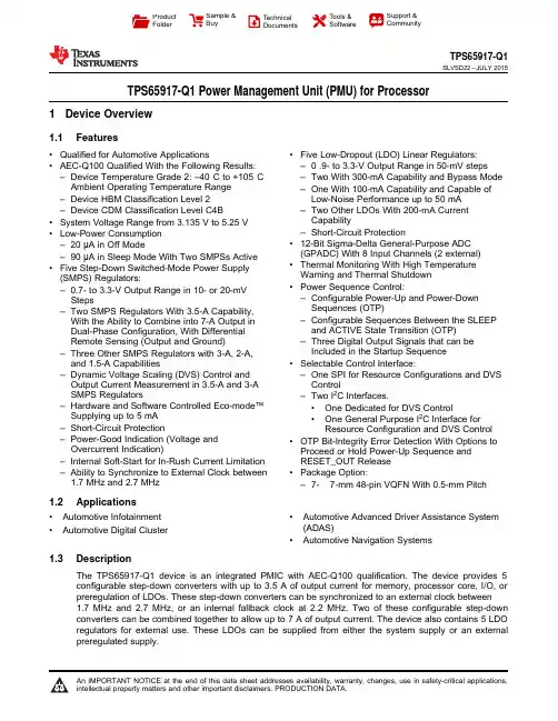
ProductFolderSample &BuyTechnical Documents Tools &SoftwareSupport &CommunityTPS65917-Q1SLVSD22–JULY 2015TPS65917-Q1Power Management Unit (PMU)for Processor1Device Overview1.1Features•Qualified for Automotive Applications•Five Low-Dropout (LDO)Linear Regulators:•AEC-Q100Qualified With the Following Results:–0.9-to 3.3-V Output Range in 50-mV steps –Device Temperature Grade 2:–40°C to +105°C –Two With 300-mA Capability and Bypass Mode Ambient Operating Temperature Range –One With 100-mA Capability and Capable of –Device HBM Classification Level 2Low-Noise Performance up to 50mA –Device CDM Classification Level C4B–Two Other LDOs With 200-mA Current Capability•System Voltage Range from 3.135V to 5.25V –Short-Circuit Protection•Low-Power Consumption •12-Bit Sigma-Delta General-Purpose ADC –20μA in Off Mode(GPADC)With 8Input Channels (2external)–90μA in Sleep Mode With Two SMPSs Active •Thermal Monitoring With High Temperature •Five Step-Down Switched-Mode Power Supply Warning and Thermal Shutdown (SMPS)Regulators:•Power Sequence Control:–0.7-to 3.3-V Output Range in 10-or 20-mV –Configurable Power-Up and Power-Down StepsSequences (OTP)–Two SMPS Regulators With 3.5-A Capability,–Configurable Sequences Between the SLEEP With the Ability to Combine into 7-A Output in and ACTIVE State Transition (OTP)Dual-Phase Configuration,With Differential Remote Sensing (Output and Ground)–Three Digital Output Signals that can be Included in the Startup Sequence –Three Other SMPS Regulators with 3-A,2-A,and 1.5-A Capabilities•Selectable Control Interface:–Dynamic Voltage Scaling (DVS)Control and –One SPI for Resource Configurations and DVS Output Current Measurement in 3.5-A and 3-A ControlSMPS Regulators–Two I 2C Interfaces.–Hardware and Software Controlled Eco-mode™•One Dedicated for DVS ControlSupplying up to 5mA •One General Purpose I 2C Interface for –Short-Circuit ProtectionResource Configuration and DVS Control–Power-Good Indication (Voltage and •OTP Bit-Integrity Error Detection With Options to Overcurrent Indication)Proceed or Hold Power-Up Sequence and –Internal Soft-Start for In-Rush Current Limitation RESET_OUT Release –Ability to Synchronize to External Clock between •Package Option:1.7MHz and2.7MHz–7-×7-mm 48-pin VQFN With 0.5-mm Pitch 1.2Applications•Automotive Infotainment •Automotive Advanced Driver Assistance System (ADAS)•Automotive Digital Cluster•Automotive Navigation Systems1.3DescriptionThe TPS65917-Q1device is an integrated PMIC with AEC-Q100qualification.The device provides 5configurable step-down converters with up to 3.5A of output current for memory,processor core,I/O,or preregulation of LDOs.These step-down converters can be synchronized to an external clock between 1.7MHz and 2.7MHz,or an internal fallback clock at 2.2MHz.Two of these configurable step-down converters can be combined together to allow up to 7A of output current.The device also contains 5LDO regulators for external use.These LDOs can be supplied from either the system supply or an external preregulated supply.An IMPORTANT NOTICE at the end of this data sheet addresses availability,warranty,changes,use in safety-critical applications,intellectual property matters and other important disclaimers.PRODUCTION DATA.TPS65917-Q1SLVSD22– The power-up and power-down controller is configurable and can support any power-up and power-down sequences(OTP based).As an additional safety feature,the OTP bit-integrity error-detection feature provides the option to stop the power-up sequence if an error is detected.The TPS65917-Q1device includes an internal32-kHz RC oscillator to sequence all resources during power up and power down.All LDOs and SMPS converters can be controlled by the SPI or I2C interface,or by power request signals.In addition,voltage scaling registers allow transition of the SMPS to different voltages by SPI,I2C,or roof-and-floor control.GPIO functionality is available and3GPIOs can be configured as part of the power-up sequence to control external resources.The fallback clock of the step-down converters can be output through the SYNCCLKOUT pin to provide synchronization clock to external resources.Power request signals enable power mode control for power optimization.The device includes a general-purpose sigma-delta analog-to-digital converter(ADC)with8channels(2with external access).The TPS65917-Q1device is available in a48-pin VQFN package with a0.5-mm pitch.Device Information(1)PART NUMBER PACKAGE BODY SIZE(NOM)TPS65917-Q1VQFN(48)7.00mm×7.00mm(1)For all available packages,see the orderable addendum at the end of the data sheet.2Device Overview Copyright©2015,Texas Instruments IncorporatedSubmit Documentation FeedbackProduct Folder Links:TPS65917-Q1TPS65917-Q1 SLVSD22–JULY20151.4Functional DiagramFigure1-1.Functional DiagramCopyright©2015,Texas Instruments Incorporated Device Overview3Submit Documentation FeedbackProduct Folder Links:TPS65917-Q1TPS65917-Q1SLVSD22– 2Device and Documentation Support2.1Documentation Support2.1.1Related DocumentationFor related documentation see the following:Guide to Using the GPADC in TPS65903x and TPS6591x Devices,SLIA0872.2Community ResourcesThe following links connect to TI community resources.Linked contents are provided"AS IS"by the respective contributors.They do not constitute TI specifications and do not necessarily reflect TI's views;see TI's Terms of Use.TI E2E™Online Community TI's Engineer-to-Engineer(E2E)Community.Created to foster collaboration among engineers.At ,you can ask questions,share knowledge,explore ideas and help solve problems with fellow engineers.Design Support TI's Design Support Quickly find helpful E2E forums along with design support tools and contact information for technical support.2.3TrademarksEco-mode,E2E are trademarks of Texas Instruments.All other trademarks are the property of their respective owners.2.4Electrostatic Discharge CautionThese devices have limited built-in ESD protection.The leads should be shorted together or the device placed in conductive foam during storage or handling to prevent electrostatic damage to the MOS gates.2.5GlossarySLYZ022—TI Glossary.This glossary lists and explains terms,acronyms,and definitions.3Mechanical,Packaging,and Orderable InformationThe following pages include mechanical,packaging,and orderable information.This information is the most current data available for the designated devices.This data is subject to change without notice and revision of this document.For browser-based versions of this data sheet,refer to the left-hand navigation.4Mechanical,Packaging,and Orderable Information Copyright©2015,Texas Instruments IncorporatedSubmit Documentation FeedbackProduct Folder Links:TPS65917-Q1IMPORTANT NOTICETexas Instruments Incorporated(TI)reserves the right to make corrections,enhancements,improvements and other changes to its semiconductor products and services per JESD46,latest issue,and to discontinue any product or service per JESD48,latest issue.Buyers should obtain the latest relevant information before placing orders and should verify that such information is current and complete.TI’s published terms of sale for semiconductor products(/sc/docs/stdterms.htm)apply to the sale of packaged integrated circuit products that TI has qualified and released to market.Additional terms may apply to the use or sale of other types of TI products and services.Reproduction of significant portions of TI information in TI data sheets is permissible only if reproduction is without alteration and is accompanied by all associated warranties,conditions,limitations,and notices.TI is not responsible or liable for such reproduced rmation of third parties may be subject to additional restrictions.Resale of TI products or services with statements different from or beyond the parameters stated by TI for that product or service voids all express and any implied warranties for the associated TI product or service and is an unfair and deceptive business practice.TI is not responsible or liable for any such statements. Buyers and others who are developing systems that incorporate TI products(collectively,“Designers”)understand and agree that Designers remain responsible for using their independent analysis,evaluation and judgment in designing their applications and that Designers have full and exclusive responsibility to assure the safety of Designers'applications and compliance of their applications(and of all TI products used in or for Designers’applications)with all applicable regulations,laws and other applicable requirements.Designer represents that,with respect to their applications,Designer has all the necessary expertise to create and implement safeguards that(1)anticipate dangerous consequences of failures,(2)monitor failures and their consequences,and(3)lessen the likelihood of failures that might cause harm and take appropriate actions.Designer agrees that prior to using or distributing any applications that include TI products,Designer will thoroughly test such applications and the functionality of such TI products as used in such applications.TI’s provision of technical,application or other design advice,quality characterization,reliability data or other services or information, including,but not limited to,reference designs and materials relating to evaluation modules,(collectively,“TI Resources”)are intended to assist designers who are developing applications that incorporate TI products;by downloading,accessing or using TI Resources in any way,Designer(individually or,if Designer is acting on behalf of a company,Designer’s company)agrees to use any particular TI Resource solely for this purpose and subject to the terms of this Notice.TI’s provision of TI Resources does not expand or otherwise alter TI’s applicable published warranties or warranty disclaimers for TI products,and no additional obligations or liabilities arise from TI providing such TI Resources.TI reserves the right to make corrections, enhancements,improvements and other changes to its TI Resources.TI has not conducted any testing other than that specifically described in the published documentation for a particular TI Resource.Designer is authorized to use,copy and modify any individual TI Resource only in connection with the development of applications that include the TI product(s)identified in such TI Resource.NO OTHER LICENSE,EXPRESS OR IMPLIED,BY ESTOPPEL OR OTHERWISE TO ANY OTHER TI INTELLECTUAL PROPERTY RIGHT,AND NO LICENSE TO ANY TECHNOLOGY OR INTELLECTUAL PROPERTY RIGHT OF TI OR ANY THIRD PARTY IS GRANTED HEREIN,including but not limited to any patent right,copyright,mask work right,or other intellectual property right relating to any combination,machine,or process in which TI products or services are rmation regarding or referencing third-party products or services does not constitute a license to use such products or services,or a warranty or endorsement e of TI Resources may require a license from a third party under the patents or other intellectual property of the third party,or a license from TI under the patents or other intellectual property of TI.TI RESOURCES ARE PROVIDED“AS IS”AND WITH ALL FAULTS.TI DISCLAIMS ALL OTHER WARRANTIES OR REPRESENTATIONS,EXPRESS OR IMPLIED,REGARDING RESOURCES OR USE THEREOF,INCLUDING BUT NOT LIMITED TO ACCURACY OR COMPLETENESS,TITLE,ANY EPIDEMIC FAILURE WARRANTY AND ANY IMPLIED WARRANTIES OF MERCHANTABILITY,FITNESS FOR A PARTICULAR PURPOSE,AND NON-INFRINGEMENT OF ANY THIRD PARTY INTELLECTUAL PROPERTY RIGHTS.TI SHALL NOT BE LIABLE FOR AND SHALL NOT DEFEND OR INDEMNIFY DESIGNER AGAINST ANY CLAIM, INCLUDING BUT NOT LIMITED TO ANY INFRINGEMENT CLAIM THAT RELATES TO OR IS BASED ON ANY COMBINATION OF PRODUCTS EVEN IF DESCRIBED IN TI RESOURCES OR OTHERWISE.IN NO EVENT SHALL TI BE LIABLE FOR ANY ACTUAL, DIRECT,SPECIAL,COLLATERAL,INDIRECT,PUNITIVE,INCIDENTAL,CONSEQUENTIAL OR EXEMPLARY DAMAGES IN CONNECTION WITH OR ARISING OUT OF TI RESOURCES OR USE THEREOF,AND REGARDLESS OF WHETHER TI HAS BEEN ADVISED OF THE POSSIBILITY OF SUCH DAMAGES.Unless TI has explicitly designated an individual product as meeting the requirements of a particular industry standard(e.g.,ISO/TS16949 and ISO26262),TI is not responsible for any failure to meet such industry standard requirements.Where TI specifically promotes products as facilitating functional safety or as compliant with industry functional safety standards,such products are intended to help enable customers to design and create their own applications that meet applicable functional safety standards and ing products in an application does not by itself establish any safety features in the application.Designers must ensure compliance with safety-related requirements and standards applicable to their applications.Designer may not use any TI products in life-critical medical equipment unless authorized officers of the parties have executed a special contract specifically governing such use. Life-critical medical equipment is medical equipment where failure of such equipment would cause serious bodily injury or death(e.g.,life support,pacemakers,defibrillators,heart pumps,neurostimulators,and implantables).Such equipment includes,without limitation,all medical devices identified by the U.S.Food and Drug Administration as Class III devices and equivalent classifications outside the U.S.TI may expressly designate certain products as completing a particular qualification(e.g.,Q100,Military Grade,or Enhanced Product). Designers agree that it has the necessary expertise to select the product with the appropriate qualification designation for their applications and that proper product selection is at Designers’own risk.Designers are solely responsible for compliance with all legal and regulatory requirements in connection with such selection.Designer will fully indemnify TI and its representatives against any damages,costs,losses,and/or liabilities arising out of Designer’s non-compliance with the terms and provisions of this Notice.Mailing Address:Texas Instruments,Post Office Box655303,Dallas,Texas75265Copyright©2017,Texas Instruments Incorporated。
4 起重机及其组成部分的工作级别 4.1工作级别的划分 4.1.1工作级别划分的内容起重机通过起升和移动荷重(指起重机所负荷及吊运的重物的质量)在其名义起重量以内的重物来实现物料搬运作业,但在不同场合使用的起重机其工作任务差别很大,即其预期寿命、工作要求、起吊荷重、承受载荷、总工作循环数与总工作时间等都会有很大的不同,为经济合理地选择和安全可靠地使用起重机,必须对其整机及组成部分进行工作级别的划分,包括:1) 起重机整机的分级; 2) 机构的分级;3) 结构件及机械零件的分级。
4.1.2 分级的基础:1) 使用等级:用起重机的总工作循环数,机构总使用小时数,结构件或机械零件总应力循环数等来表示。
2) 载荷状态:用起重机的荷重谱、机构的载荷谱、结构件或机械零件的应力谱等来表示。
4.2 起重机整机的分级 4.2.1 分级目的1) 为起重机设计、制造和使用各方提供一个关于该起重机设计预期工作状况的基本规定,以作为签订订货及制造合同时确定技术内容的共同基础;2) 为起重机设计和研究提供计算和分析的基础,以用于指导起重机设计,并验证它可否满足给定的使用条件及是否达到设计预期的寿命。
4.2.2 确定分级的因素确定起重机整机分级有两个因素:起重机的使用等级和起重机的荷重状态。
4.2.2.1 起重机的使用等级起重机的设计预期寿命期是指该起重机从交付使用起到预期的停止使用或最终报废为止的总期限,要考虑经济、技术、环境及设备老化等因素的影响来确定它的适当数值。
在起重机的实际使用中,这一预期寿命是用该起重机在此期限内所有工作循环数的总和,即总工作循环数来表示的。
起重机的一个工作循环是指从起吊一个荷重算起,到能开始进行下一个起吊作业为止,包括起重机运行及正常的停歇在内的一个完整的过程。
起重机总的工作循环数与它的设计预期寿命期限的长短及起重机使用的频繁情况有关。
起重机的使用等级是将可能出现的起重机总工作循环数划分成的10个级别,用U 0、U 1、U 2……U 9表示,见表4-1。
2023年注册结构工程师-专业考试(一级)考试备考题库附带答案第1卷一.全考点押密题库(共30题)1.(单项选择题)(每题1.00 分) 有一6m大开间多层砌体房屋,底层从室内地坪至楼层高度为5.4m,已知墙厚240mm,组合墙的平面尺寸如图所示。
砌体:MU10多孔砖,M7.5混合砂浆;构造柱:C20混凝土,fc=9.6MPa,钢筋:边柱、中柱均为4φ14HRB335级钢筋。
墙的高厚比β最接近于()。
A. 24.6B. 25.9C. 27.8D. 29.92.(单项选择题)(每题1.00 分) 一级公路上的一座桥梁,位于7度地震地区,由主桥和引桥组成。
其结构:主桥为三跨(70m+100m+70m)变截面预应力混凝土连续箱梁;两引桥各为5孔40m预应力混凝土小箱梁;桥台为埋置式肋板结构,耳墙长度为3500mm,背墙厚度400mm;主桥与引桥和两端的伸缩缝均为160mm。
桥梁行车道净宽15m,全宽17.5m。
设计汽车荷载(作用)公路-Ⅰ级。
[2012年真题]1.试问,该桥的全长计算值(m)与下列何项数值最为接近?()A. 640.00B. 640.16C. 640.96D. 647.963.(单项选择题)(每题1.00 分)关于保证墙梁使用阶段安全可靠工作的下述见解,要求不妥的是()。
A. 一定要进行跨中或洞口边缘处托梁正截面承载力计算B. 一定要对自承重墙梁进行墙体受剪承载力、托梁支座上部砌体局部受压承载力计算C. 一定要进行托梁斜截面受剪承载力计算D. 酌情进行托梁支座上部正截面承载力计算4.(单项选择题)(每题1.00 分) 试问,建筑的场地类别为下列何项?A. I类场地B. II类场地C. Ⅲ类场地D. IV类场地5.(单项选择题)(每题1.00 分) 假定,该底层柱轴压比为0.5,试问,该底层框架柱柱端加密区的箍筋配置选用下列何项才能满足规程的最低要求?()提示:①按《混凝土异形柱结构技术规程》(JGJ149—2006)作答;②扣除重叠部分箍筋的体积。
第一章专用汽车的总体设计1 总布置参数的确定1.1 专用汽车的外廓尺寸(总长、总宽和总高)1.1.1 长①载货汽车≤12m②半挂汽车列车≤16.5m1.1.2 宽≤2.5m(不含后视镜、侧位灯、示廓灯、转向指示灯、可折卸装饰线条、挠性挡泥板、折叠式踏板、防滑链以及轮胎与地面接触部分的变形等)1.1.3 高≤4m(汽车处于空载状态,顶窗、换气装置等处于关闭状态)1.1.4 车外后视镜单侧外伸量不得超出汽车或挂车最大宽度处250mm1.1.5 汽车的顶窗、换气装置等处于开启状态时不得超出车高300mm1.2专用汽车的轴距和轮距1.2.1 轴距轴距是影响专用汽车基本性能的主要尺寸参数。
轴距的长短除影响汽车的总长外,还影响汽车的轴荷分配、装载量、装载面积或容积、最小转弯半径、纵向通过半径等,此外,还影响汽车的操纵性和稳定性等。
1.2.2 轮距轮距除影响汽车总宽外,还影响汽车的总重、机动性和横向稳定性。
1.3专用汽车的轴载质量及其分配专用汽车的轴载质量是根据公路运输车辆的法规限值和轮胎负荷能力确定的。
1.3.1 各类专用汽车轴载质量限值(JT701-88《公路工程技术标准》)前轴轴载质量(kg ) ≤3000 ≤5000 ≤7000 ≤6000 后轴轴载质量(kg ) ≤7000≤10000≤13000≤240001.3.2 基本计算公式 A 已知条件a ) 底盘整备质量G 1b ) 底盘前轴负荷g 1c ) 底盘后轴负荷Z 1d ) 上装部分质心位置L 2e ) 上装部分质量G 2f ) 整车装载质量G 3(含驾驶室乘员)g ) 装载货物质心位置L 3(水平质心位置)h ) 轴距)(21l l l +B 上装部分轴荷分配计算(力矩方程式)g 2(前轴负荷)×(121l l +)(例图1)=G 2(上装部分质量)×L 2(质心位置)例图1g 2(前轴负荷)=12221)()(l l L G +⨯上装部分质心位置上装部分质量则后轴负荷222g G Z -= C 载质量轴荷分配计算g 3(前轴负荷)×)21(1l l +=G 3×L 3(载质量水平质心位置)g 3(载质量前轴负荷)=13321)()(l l L G +⨯装载货物水平质心位置整车装载质量则后轴负333g G Z -= D 空车轴荷分配计算g 空(前轴负荷)=g 1(底盘前轴负荷)+g 2(上装部分前轴轴荷) Z 空(后轴负荷)=Z 1(底盘后轴负荷)+Z 2(上装部分后轴轴荷) G 空(整车整备质量)=空空Z g + E 满车轴荷分配计算 g 满(前轴负荷)=g 空+g 3 Z 满(后轴负荷)=Z 空+Z 3 G 满(满载总质量)=g 满+Z 满 1.4专用汽车的质心位置计算专用汽车的质心位置影响整车的轴荷分配、行驶稳定性和操纵性等,在总体设计时必须要慎重全面考虑计算或验算,特别是质心高度是愈低愈好。
1、理解环和掌握法古拉第电滋感应定律。
2、会求感生电动势和动生电动势。
3、理解自感、祸流、电掬驱动和电嘟阻尼[例题1](2024•下城区校级模拟)在竖直方向的匀强磁场中,水平放置一闭合金属圆环,面积为A.0~1s内感应电流的磁场在圆环圆心处的方向向上B.1~2s内通过圆环的感应电流的方向与图甲所示方向相反A.kL2 R例题3](2023秋•渝中区校级期末)如图甲,圆心为A .线圈受到的安培力的合力向右B .线圈中电流沿顺时针方向C .感应电流的大小πr 2B 0t 0RD .细杆对线框的弹力逐渐增大=MN ;沿v 2方向运动时,l =0.[例题4](2023秋•玄武区校级期末)如图所示,先后以速度A.线圈中的感应电动势之比为B.线圈中的感应电流之比为C.线圈中产生的焦耳热之比A.P点的电势高于Q点,B.P点的电势高于Q点,C.Q点的电势高于P点,A .Bv 2r 例题8](多选)(2024A .cd 棒全部进入磁场时,cd 棒产生的电动势大小为BLvB .t 1时刻cd 棒所受的安培力大小为BI 1L 2C .2t 1时刻ab 棒的速度大小为(1―I 22I 1)v mv匀强磁场中,磁感应强度大小为B,导轨间距最窄处为一狭缝(狭缝宽度不计),取狭缝所在处O点为坐标原点,狭缝右侧两导轨与x轴夹角均为θ,导轨左端通过单刀双掷开关S可以与电容C或电阻R相连,导轨上有一足够长且不计电阻的金属棒与x轴垂直,在外力F(大小未知)的作用下从O点开始以速度v向右匀速运动,若某时刻开关S接1,外力用F1表示,通过金属棒电流的大小用I1表示;若某时刻开关S接2,外力用F2表示,通过金属棒电流的大小用I2表示。
关于外力、电流大小随时间变化的图象关系正确的是( )A.B.C.D.[例题10](2024•辽宁模拟)某小组设计了一种汽车电磁感应悬架系统模型,其原理示意图如图所示。
质量为m的重物系统MNPQ内存在方向水平、垂直纸面向里的匀强磁场,磁感应强度大小为B,系统正下方的水平地面上固定有闭合的单匝矩形线圈,其电阻为R、ab边长为L。
ICS21.020J 09 DB33 浙江省地方标准DB33/T XXXXX—2018特种设备使用安全管理分类评价规范Evaluation specification for safety management classification of special equipment(报批稿)2018-XX-XX发布2018-XX-XX实施前言本标准依据GB/T 1.1-2009给出的规则起草。
本标准由浙江省质量技术监督局提出并归口。
本标准起草单位:绍兴市质量技术监督局、绍兴市标准化研究院、绍兴市上虞区质量技术监督局、嵊州市质量技术监督局、浙江新和成股份有限公司。
本标准主要起草人:寿明耀、李丰庆、诸源、沈连军、陈巍、郑建伟、叶华、何健、李博斌、郭培培、黄翔、胡苗火、裘益民、胡肖辉。
本标准为首次发布。
特种设备使用安全管理分类评价规范1 范围本标准规定了特种设备使用安全管理分类评价的术语和定义、基本要求、评价主体、评价方式、分类评价、评价结果应用等要求。
本标准适用于《特种设备目录》范围内特种设备的使用安全管理分类评价。
2 规范性引用文件下列文件对于本文件的应用是必不可少的。
凡是注日期的引用文件,仅所注日期的版本适用于本文件。
凡是不注日期的引用文件,其最新版本(包括所有的修改单)适用于本文件。
GB 4387 工业企业厂内铁路、道路运输安全规程GB 5226.1 机械电气安全机械电气设备第1部分:通用技术条件TSG 08 特种设备使用管理规则TSG Q7016 起重机械安装改造重大修理监督检验规则3 术语和定义下列术语和定义适用于本文件。
3.1特种设备对人身和财产安全有较大危险性的锅炉、压力容器(含气瓶)、压力管道、电梯、起重机械、客运索道、大型游乐设施、场(厂)内专用机动车辆。
3.2使用单位具有特种设备使用管理权的单位或者具有完全民事行为能力的自然人,一般是特种设备的产权单位(产权所有人,下同),也可以是产权单位通过符合法律规定的合同关系确立的特种设备实际使用管理者。
1.闭口系与外界无物质交换,系统内质量保持恒定,那么系统内质量保持恒定的热力系一定是闭口系统吗? 不一定,稳定流动系统内质量也保持恒定。
2.有人认为开口系统内系统与外界有物质交换,而物质又与能量不可分割,所以开口系统不可能是绝热系。
对不对,为什么?不对,绝热系的绝热是指热能单独通过系统边界进行传递(传热量),随物质进出的热能(准确地说是热力学能)不在其中。
3.平衡状态与稳定状态有何区别和联系?平衡状态一定是稳定状态,稳定状态则不一定是平衡状态。
4.倘使容器中气体的压力没有改变,试问安装在该容器上的压力表的读数会改变吗?绝对压力计算公式p =p b +p g (p > p b ), p = p b -p v (p < p b )中,当地大气压是否必定是环境大气压?当地大气压p b 改变,压力表读数就会改变。
当地大气压p b 不一定是环境大气压。
5.温度计测温的基本原理是什么? 6.经验温标的缺点是什么?为什么?不同测温物质的测温结果有较大的误差,因为测温结果依赖于测温物质的性质。
7.促使系统状态变化的原因是什么?举例说明。
有势差(温度差、压力差、浓度差、电位差等等)存在。
8.分别以图1-20所示的参加公路自行车赛的运动员、运动手枪中的压缩空气、杯子里的热水和正在运行的电视机为研究对象,说明这些是什么系统。
参加公路自行车赛的运动员是开口系统、运动手枪中的压缩空气是闭口绝热系统、杯子里的热水是开口系统(闭口系统——忽略蒸发时)、正在运行的电视机是闭口系统。
9.家用电热水器是利用电加热水的家用设备,通常其表面散热可忽略。
取正在使用的家用电热水器为控制体(但不包括电加热器),这是什么系统?把电加热器包括在研究对象内,这是什么系统?什么情况下能构成孤立系统?不包括电加热器为开口(不绝热)系统(a 图)。
包括电加热器则为开口绝热系统(b 图)。
将能量传递和质量传递(冷水源、热水汇、热源、电源等)全部包括在内,构成孤立系统。
1第一章汽车使用条件及性能指标第一节汽车使用条件第二节汽车运行工况第三节汽车使用性能指标2第一节汽车使用条件 汽车使用条件,是指影响汽车完成运输工作的各类外界条件。
主要包括气候条件、道路条件、运输条件和汽车安全运行技术条件等。
3一、气候条件气候条件:由气候的自然变化构成的影响因素,包括大气温度、湿度以及雨、雪、风沙、雾等方面的影响。
我国幅员辽阔,各地气候条件差异很大。
环境温度对汽车特别对发动机的热工况影响很大。
在炎热地区,发动机容易过热,工作效率低,燃料消耗增加。
在气候干燥、风沙大的地区,汽车及其各总成的运动副易因风沙侵入,而加剧磨损。
4一、气候条件在气候潮湿和雨季地区及沿海地区,如果发动机、驾驶室、车厢的防水和泄水不良,将引起零件锈蚀,以及因潮湿使电气系统工作不可靠。
另外,大气湿度过高,会降低发动机的气缸的充气效率,降低发动机的动力性和燃料经济性。
在高原地区,空气稀薄,大气压力低,水的沸点下降,且一日内温差大。
由此使发动机的混合气过浓,真空点火提前调节器失效,冷却水易沸腾,气压制动系统气压不足,以及使驾驶员体力下降。
5一、气候条件不同气候条件对车辆结构和使用提出了不同的要求。
应针对具体的气候和季节条件,使用相应的变型汽车或对标准型汽车进行技术改造,以提高车辆与气候的适应程度。
汽车运输企业需要针对当地的气候特点,合理选用汽车,并制定相应的技术措施,努力克服或减少气候条件造成的各种困难,做到合理使用,取得较佳的使用效果。
6二、道路条件道路条件是指由道路状况决定的,并影响汽车运用的因素,汽车结构、汽车运行工况、汽车技术状况都与汽车运行的道路条件密切相关。
汽车运输对道路的要求是:在充分发挥汽车速度特性的情况下,保证车辆安全行驶;满足该地区对此道路所要求的最大通行能力;车辆通过方便,乘客有舒适感;车辆通过此道路的运行材料消耗量最低,零件损坏最小。
7二、道路条件车辆运行速度和道路通行能力是道路条件的主要特征指标。
它们是确定道路等级、车道宽度、车道数、路面强度以及道路纵断面和横断面的依据。
道路条件对汽车运行速度、行驶平顺性及装载质量利用程度的主要影响来自道路等级和道路养护水平。
例如,汽车在良好路面上行驶,可获得较高车速和良好燃料经济性;汽车在崎岖不平的道路上行驶,平均技术速度低,需要频繁地进行换档和制动操作,加剧了零件的磨损,增加了油耗和驾驶员工作强度;路面不平也使零部件冲击载荷增加,加剧汽车行走系损伤和轮胎磨损。
81.道路等级根据公路交通量及其使用任务和性质,交通部标准《公路工程技术标准》将公路分为五个等级:高速公路、一级公路、二级公路、三级公路、四级公路91.道路等级高速公路。
一般能适应按折算成小客车的年平均昼夜交通量为25000辆以上,具有特别重要的政治、经济意义,专供汽车分道高速行驶,并实行全线控制出入的公路。
一级公路。
一般能适应按折算成小客车的年平均昼夜交通量为15000~30000辆,为连接重要的政治、经济中心,通往重点工矿区,可供汽车分道行驶,并部分控制出入及部分立体交叉的公路。
101.道路等级二级公路。
适应按各种车辆折合成中型货车的年平均昼夜汽车交通量为3000~7500辆,为连接政治、经济中心及大型工矿区的干线公路,或交通运输繁忙的城郊公路。
三级公路。
适应按各种车辆折合成中型货车的年平均昼夜汽车交通量为1000~4000辆,为沟通县及县以上城市的一般干线公路。
四级公路。
适应按各种车辆折合成中型货车的年平均昼夜汽车交通量为双车道1500辆以下、单车道200辆以下,为沟通县、乡、村等支线公路。
111.道路等级《标准》将每级公路规定了相应的技术标准,如车道宽、车道数、最小停车视线距、纵坡、平曲线半径和路面等级等。
标准中规定的路线参考取值,均在保证设计车速的前提下,考虑了汽车行驶安全性、舒适性、驾驶员的视觉和心理反应。
122.公路技术特性影响公路使用质量和车辆使用效率的线路主要技术特性:在水平面内是曲线段的平曲线半径 在纵断面内是纵坡、纵坡长度、竖曲线半径在横断面内是车道宽度、车道数和路肩宽度等。
132.公路技术特性汽车弯道行驶,受离心力作用可能会引起侧滑,恶化汽车的操纵性,降低乘员的舒适性,严重时可能翻车。
在小平曲线半径行驶的车辆轮胎侧向变形增大,磨损增加,车轮滚动阻力增加,车辆油耗增加。
曲线路段影响驾驶员的视线,夜间行车光照距离在曲线段也比直线段短,对行车安全不利。
很长直线路段对行车安全也不利,所以高速公路都避免采用直长路线型。
当条件不许可时,可设超高或缓和曲线。
缓和曲线使作用在汽车上的离心力逐渐变化,便于驾驶员平缓操纵转向盘,保证行车安全。
142.公路技术特性公路纵坡使汽车动力消耗增大,后备功率降低,燃料消耗增加。
另外,公路凸形变更也影响驾驶员的视距。
权衡汽车运输指标和修建费用两个要求,是公路修建前可行性论证的重要内容。
汽车运行工况和安全性与路面质量有关。
路面要求具有足够的强度、很高稳定性、良好平整度以及适当粗糙度,以保证汽车的附着条件和最小的运行阻力。
路面平整度是路面的主要使用特性之一,影响汽车运行速度、动载荷、轮胎磨损、货物完好性及乘员舒适性,从而影响汽车利用指标和使用寿命。
路面平整度与汽车运行速度163.公路养护水平公路养护水平的两个评定指标是“好路率”和“养护质量综合值”。
根据“公路养护质量检查评定暂行办法”,将公路养护质量分为优、良、次、差四个等级。
评定项目包括路面平整、路拱适度、行车顺适、路肩整洁、边坡稳定、标志完善鲜明、行道树齐全。
满分为100分,其中路面、路基和其它分别为50、20和30分。
好路率/养护质量综合值已知某公路的总里程194.公路养护水平对汽车使用性能的影响1)油耗 为了确切的路面质量对汽车百公里油耗的影响,选择典型路段进行试验。
测取在不同路段的路面分值和汽车的百公里油耗,回归分析得到指数方程Qs 为定车速下汽车的百公里油耗(L/100km);x 为路面分;a 和b 为为回归系数。
在车速为50km/h 的情况下,试验路段的路面分依次为18分和49分时,油耗分别为28.43L/100km 和26.01L/100km ,即路面分从18增至49时,油耗将下降8.5%。
bx s ae Q −=202)车辆维护费用一些研究曾对一些地区的车辆维护费用和道路养护质量的关系进行了统计分析,得到统计结果,对其进行回归分析,可得y=0.2265-0.1586ln xy 为每公里维护费用,元/公里;x 为道路养护综合值。
养护综合值与车辆维护费用224.公路养护水平对汽车使用性能的影响3)车辆大修费用根据河北省某年公路好路率与汽车大修间隔里程统计数据,通过相关分析可知,好路率与汽车大修里程间存在关系式:y =-29.909+0.6374xy 为汽车大修里程,万公里;x 为好路率(%)。
23三、汽车高速公路使用条件据统计,国外高速公路死亡事故率仅为普通公路的1/3~1/2,一般性事故率是普通公路的1/5~1/3。
而我国情况则相反,1995年高速公路仅为公路总里程的0.2%,但交通事故却占1.5%,死亡人数占1.36%,直接经济损失占4.36%。
有关资料表明,在高速公路的交通事故中,汽车机械故障造成的比例逐年升高。
例如,在京石高速公路河北段双幅路开通后不到两年的时间里,因机械故障引发的交通事故就达96起,其中制动失效和不良的就有58起。
24高速公路行驶的安全条件①要严格遵守交通法规按照限速规定行驶。
②为了防止汽车在高速公路上发生故障,妨碍交通安全畅通,在进入高速公路前要对汽车的燃料、润滑油、冷却液、转向器、制动器、灯光、轮胎等部件以及汽车的装载和固定情况进行仔细检查,使得车况处于最佳状态。
③车辆进入高速公路后应使车速达到50km/h以上。
通过匝道进入高速公路的汽车须在加速车道提高车速,并在不妨碍主车道上其它车辆行驶的情况下,驶入主车道。
25高速公路行驶的安全条件④在正常情况下,汽车应在主车道上行驶,只有当前方有障碍物或需要超越前车时,方可变换到超车道上行驶,通过障碍物或超越前车后,应驶回主车道。
不准车辆在超车道长时间行驶或骑、压车道分界线行驶。
⑤为了减轻碰撞时的人员伤亡,配有安全带的汽车前排司乘人员应佩带安全带。
货运汽车除驾驶室外,其它部位一律不得载人。
客车行车中乘客不许在汽车中站。
26高速公路行驶的安全条件⑥高速公路车不许随意停车。
为了防止追尾或侧滑的危险,汽车发生故障时不得采取急制动。
而应立即打开右转向灯,将车停放在右侧紧急停车带或右侧路肩。
停车后无关人员应迅速撤至护栏外侧。
当故障排除重新行驶时,应及时将车速提高到50km/h以上。
然后,在不影响其它车辆行驶的情况下驶入主车道。
当车辆因故障或事故无法离开主车道时,须开启车辆危险报警闪光灯,夜间还应开启示宽灯和尾灯,并在车后100m外设置故障警告标志。
同时,通知有关管理机构,不得随意拦截车辆。
27高速公路行驶的安全条件⑦当交通受阻时,要按顺序停车,等待有关人员处理,不得在路肩上行驶,以免影响救护车、公安交通和管理巡逻车通行。
⑧在高速公路上汽车不许调头、倒车和穿越中央分隔带,不许进行试车,也不许在匝道上超车和停车。
⑨当遇有大风、雨、雾或路面积雪、结冰时,要注意可变交通标志或临时交通标志,遵守管理部门采取的限速和封闭车道的管制措施。
28四、运输条件运输条件,是指由运输对象的特点和要求所决定的,影响车辆使用的各种因素。
汽车运输可分为货运和客运。
货运条件主要包括货物类别、货物运量、货运距离、装卸条件、运输类型和组织特点。
客运对汽车使用性能的最基本要求是为旅客提供最佳的方便性。
29四、运输条件1.货物类别货物是从接受承运起到送交收货人止的所有商品或物资。
通常,根据运输过程中的货物装卸方法、运输和保管条件以及批量对货物分类。
按装卸方法,分为堆积、计件和灌装三类。
按运输和保管条件,分为普通货物和特殊货物。
按货物批量,分为小批和大批货物。
30四、运输条件2.货运量按托运货物的批量,货运量分为零担和整车两类。
凡是一次托运货物在3t以上为整车货物,不足3吨为零担货物。
需要较长时间和较多车辆,才能运完的整车货物为大宗货物,而短时间内或少数车辆即能全部运完的货物为小宗货物。
运输行业应配备不同吨位的车辆,才能合理地组织运输,提高运输经济效益。
31四、运输条件3.货物运距货物运距是货物由装货点至卸货点间的运输距离,一般用公里(km)作为计量单位。
货物运距在很大程度上影响运输车辆利用效率指标,并对车辆的结构和性能提出不同的要求。
当运距较短时,要求车辆结构能很好地适应货物装卸的要求,以缩短车辆货物的装卸作业时间,提高车辆短运距的生产率。
长途运输车辆运输生产率随车辆的速度性能提高和载质量的增大而显著增加。