多区域OSPF配置
- 格式:ppt
- 大小:2.10 MB
- 文档页数:66
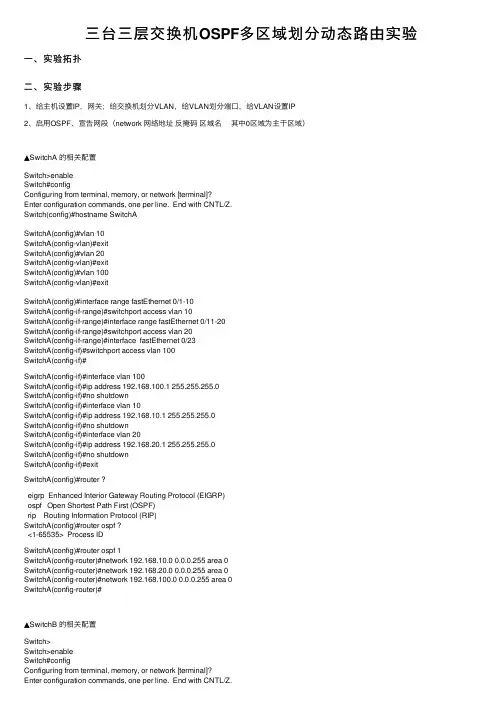
三台三层交换机OSPF多区域划分动态路由实验⼀、实验拓扑⼆、实验步骤1、给主机设置IP,⽹关;给交换机划分VLAN,给VLAN划分端⼝,给VLAN设置IP2、启⽤OSPF、宣告⽹段(network ⽹络地址反掩码区域名其中0区域为主⼲区域)▲SwitchA 的相关配置Switch>enableSwitch#configConfiguring from terminal, memory, or network [terminal]?Enter configuration commands, one per line. End with CNTL/Z.Switch(config)#hostname SwitchASwitchA(config)#vlan 10SwitchA(config-vlan)#exitSwitchA(config)#vlan 20SwitchA(config-vlan)#exitSwitchA(config)#vlan 100SwitchA(config-vlan)#exitSwitchA(config)#interface range fastEthernet 0/1-10SwitchA(config-if-range)#switchport access vlan 10SwitchA(config-if-range)#interface range fastEthernet 0/11-20SwitchA(config-if-range)#switchport access vlan 20SwitchA(config-if-range)#interface fastEthernet 0/23SwitchA(config-if)#switchport access vlan 100SwitchA(config-if)#SwitchA(config-if)#interface vlan 100SwitchA(config-if)#ip address 192.168.100.1 255.255.255.0SwitchA(config-if)#no shutdownSwitchA(config-if)#interface vlan 10SwitchA(config-if)#ip address 192.168.10.1 255.255.255.0SwitchA(config-if)#no shutdownSwitchA(config-if)#interface vlan 20SwitchA(config-if)#ip address 192.168.20.1 255.255.255.0SwitchA(config-if)#no shutdownSwitchA(config-if)#exitSwitchA(config)#router ?eigrp Enhanced Interior Gateway Routing Protocol (EIGRP)ospf Open Shortest Path First (OSPF)rip Routing Information Protocol (RIP)SwitchA(config)#router ospf ?<1-65535> Process IDSwitchA(config)#router ospf 1SwitchA(config-router)#network 192.168.10.0 0.0.0.255 area 0SwitchA(config-router)#network 192.168.20.0 0.0.0.255 area 0SwitchA(config-router)#network 192.168.100.0 0.0.0.255 area 0SwitchA(config-router)#▲SwitchB 的相关配置Switch>Switch>enableSwitch#configConfiguring from terminal, memory, or network [terminal]?Enter configuration commands, one per line. End with CNTL/Z.Switch(config)#vlan 30Switch(config-vlan)#exitSwitch(config)#vlan 40Switch(config-vlan)#exitSwitch(config)#vlan 101Switch(config-vlan)#exitSwitch(config)#vlan 200Switch(config-vlan)#exitSwitch(config)#hostname SwitchBSwitchB(config)#interface range fastEthernet 0/1-10SwitchB(config-if-range)#switchport access vlan 30SwitchB(config-if-range)#interface range fastEthernet 0/11-20 SwitchB(config-if-range)#switchport access vlan 40SwitchB(config-if-range)#interface fastEthernet 0/23SwitchB(config-if)#switchport access vlan 101SwitchB(config-if)#interface fastEthernet 0/24SwitchB(config-if)#switchport access vlan 200SwitchB(config-if)#SwitchB(config-if)#exitSwitchB(config)#interface vlan 101SwitchB(config-if)#ip address 192.168.100.2 255.255.255.0 SwitchB(config-if)#no shutdownSwitchB(config-if)#interface vlan 200SwitchB(config-if)#ip address 192.168.200.1 255.255.255.0 SwitchB(config-if)#no shutdownSwitchB(config-if)#interface vlan 30SwitchB(config-if)#ip address 192.168.30.1 255.255.255.0 SwitchB(config-if)#no shutdownSwitchB(config-if)#interface vlan 40SwitchB(config-if)#ip address 192.168.40.1 255.255.255.0 SwitchB(config-if)#no shutdownSwitchB(config-if)#exitSwitchB(config)#route ospf 1SwitchB(config-router)#network 192.168.100.0 0.0.0.255 area 0 SwitchB(config-router)#network 192.168.30.0 0.0.0.255 area 0 SwitchB(config-router)#network 192.168.200.0 0.0.0.255 area 1 SwitchB(config-router)#network 192.168.40.0 0.0.0.255 area 1 SwitchB(config-router)#▲SwitchC 的相关配置Switch>Switch>enableSwitch#configConfiguring from terminal, memory, or network [terminal]? Enter configuration commands, one per line. End with CNTL/Z. Switch(config)#hostname SwitchCSwitchC(config)#vlan 50SwitchC(config-vlan)#exitSwitchC(config)#vlan 60SwitchC(config-vlan)#exitSwitchC(config)#vlan 201SwitchC(config-vlan)#exitSwitchC(config)#interface range fastEthernet 0/1-10 SwitchC(config-if-range)#switchport access vlan 50SwitchC(config-if-range)#interface range fastEthernet 0/11-20 SwitchC(config-if-range)#switchport access vlan 60SwitchC(config-if-range)#interface fastEthernet 0/24 SwitchC(config-if)#switchport access vlan 201SwitchC(config-if)#exitSwitchC(config)#interface vlan 201SwitchC(config-if)#ip address 192.168.200.2 255.255.255.0SwitchC(config-if)#no shutdownSwitchC(config-if)#interface vlan 50SwitchC(config-if)#ip address 192.168.50.100 255.255.255.0SwitchC(config-if)#no shutdownSwitchC(config-if)#interface vlan 60SwitchC(config-if)#ip address 192.168.60.100 255.255.255.0SwitchC(config-if)#no shutdownSwitchC(config-if)#exitSwitch(config)#router ?eigrp Enhanced Interior Gateway Routing Protocol (EIGRP)ospf Open Shortest Path First (OSPF)rip Routing Information Protocol (RIP)Switch(config)#router ospf ?<1-65535> Process IDSwitch(config)#router ospf 1Switch(config-router)#network 192.168.50.0 0.0.0.255 area 1Switch(config-router)#network 192.168.60.0 0.0.0.255 area 1Switch(config-router)#network 192.168.200.0 0.0.0.255 area 1Switch(config-router)# 当三台交换机都设置好ospf动态路由后,⽤以下命令查看(在特权模式下)SwitchC#show ip route结果如图三、实验结果所有的PC间全通。
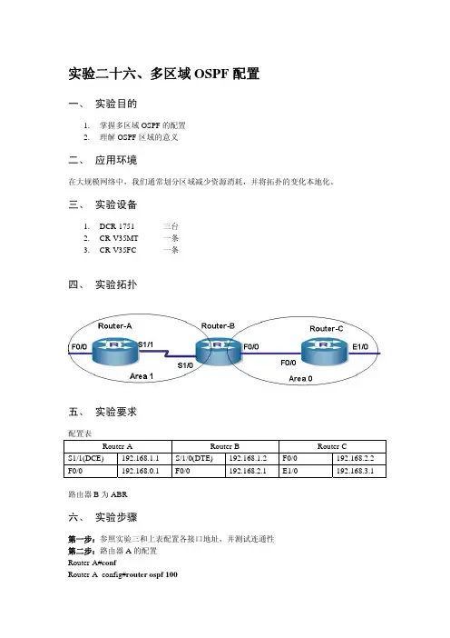
多区域 OSPFOSPF MultiArea【实验目的】了解和掌握ospf的原理,熟悉ospf多域配置步骤。
懂得如何配置Vitrul links,Transit area, Stub Area ,Totally Stubby Area, Not-so-stubby area(nssa)。
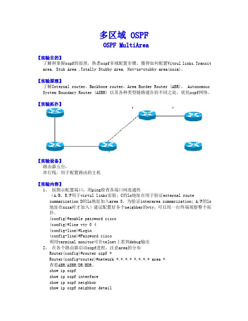
【实验原理】了解Internal router,Backbone router,Area Border Router (ABR), Autonomous System Boundary Router (ASBR) 以及各种类型链路通告的不同之处,优化ospf网络。
【实验拓扑】【实验设备】路由器五台,串行线,用于配置路由的主机【实验内容】1、按图示配置端口,用ping检查各端口间连通性(A/B,E/F用于virtul links实验; C的lo地址在用于验证external routesummarization D的lo地址加入area 8,为验证interarea summarization; A/F的lo 地址在nssa时才加入)建议配置好各个neighber的vty,可以用一台终端观察整个拓扑。
(config)#enable password cisco(config)#line vty 0 4(config-line)#Login(config-line)#Password cisco利用terminal monitor可在telnet上看到debug输出2、在各个路由器启动ospf进程,注意area的分布Router(config)#router ospf *Router(config-router)#network *.*.*.* *.*.*.* area *查看ABR/ASBR/DR/BDR。
show ip ospfshow ip ospf interfaceshow ip ospf neighborshow ip ospf neighbor detail3、 show ip route查看各router路由表,注意area 10,area 11没出现在别的router。
多区域OSPF多区域的ospf一、区域司1.为何要划分区域① 随着网络规模的不断扩大,当大型网络中的路由器运行OSPF路由协议时,路由器数量的增多会导致lsdb非常庞大,占用大量的存储空间,并使得运行spf算法的复杂度增加,导致cpu负担很重。
② 网络规模增大后,拓扑变化的概率也随之增大,网络往往处于“振荡”状态之中,造成网络中会有大量的ospf协议报文在传递,降低了网络的带宽利用率。
更为严重的是,每一次变化都会导致网络中所有的路由器重新进行路由计算。
......2.解决方法:① OSPF协议通过将自治系统划分为不同的区域来解决上述问题。
②区域是从逻辑上将路由器划分为不同的组,每个组用区域号(areaid)来标识3.区域示例4.描述①区域的边界是路由器,而不是链路。
....② 路由器可以属于不同的区域,但网段(链路)只能属于一个区域,或者说每个运行ospf的接口必须指明属于哪一个区域。
③ 划分区域后,可以在区域边界路由器上进行路由聚合,以减少到其他区域的广告数量lsa数量,还可以将网络拓扑变化带来的影响最小化。
5.区域分工的优势①降低spf计算频率②减小路由表③ 减少LSA广告的开销④ 将不稳定性限制在特定区域二、路由器的区域类型1.内部路由器:这种路由器的所有接口都属于同一个OSPF区域。
2.区域边界路由器(ABR):这种路由器可以同时属于两个以上的区域,但其中一个必须是主干区域。
ABR用于连接主干区和非主干区。
它可以是与主干区的物理连接或逻辑连接。
3.骨干路由器(backbonerouter)该类路由器至少有一个接口属于骨干区域。
因此,所有的abr和位于area0的内部路由器都是骨干路由器。
4.自治系统边界路由器(asbr):与其他as交换路由信息的路由器称为asbr。
asbr并不一定位于as的边界,它有可能是区域内路由器,也有可能是abr。
只要一台ospf路由器引入了外部路由的信息,它就成为asbr。
多区域ospf课程设计一、课程目标知识目标:1. 掌握多区域OSPF的基本概念、原理及配置方法;2. 了解多区域OSPF的网络设计,能够分析并解决多区域OSPF网络中的常见问题;3. 掌握多区域OSPF路由的传递和计算过程,能够解释多区域OSPF路由选择的原因。
技能目标:1. 能够独立完成多区域OSPF网络的搭建和配置;2. 能够使用网络仿真软件或真实设备进行多区域OSPF网络的调试和优化;3. 能够通过分析网络故障现象,找出多区域OSPF网络中的问题并进行解决。
情感态度价值观目标:1. 培养学生团队协作精神,提高在网络技术学习中的沟通与协作能力;2. 激发学生对计算机网络技术的兴趣,培养其探究精神和创新意识;3. 使学生认识到网络技术在现代社会中的重要性,增强其社会责任感和职业使命感。
课程性质分析:本课程为计算机网络技术课程的一部分,针对的是具有一定网络基础的学生。
课程内容具有较强的实践性,要求学生在学习过程中能够将理论与实践相结合。
学生特点分析:学生具备基本的网络知识,具有一定的自学能力和动手操作能力,但对多区域OSPF的深入了解和应用尚有不足。
教学要求:1. 注重理论与实践相结合,提高学生的实际操作能力;2. 采用案例教学,激发学生的兴趣和探究欲望;3. 强化团队合作,培养学生的沟通能力和协作精神。
二、教学内容1. 多区域OSPF基本概念:介绍多区域OSPF的定义、作用和优势,解释区域的概念及划分原则。
相关教材章节:第三章第二节“多区域OSPF简介”2. 多区域OSPF网络设计:讲解多区域OSPF网络的设计原则,分析不同场景下的网络设计方法。
相关教材章节:第三章第三节“多区域OSPF网络设计”3. 多区域OSPF配置与调试:详细讲解多区域OSPF的配置步骤,包括区域类型、路由器ID、网络地址等配置方法,以及使用网络仿真软件进行调试。
相关教材章节:第三章第四节“多区域OSPF配置与调试”4. 多区域OSPF路由计算与传递:分析多区域OSPF路由的计算和传递过程,解释路由选择的原因。
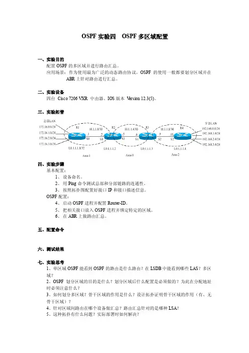
OSPF实验四OSPF多区域配置
一、实验目的
配置OSPF的多区域并进行路由汇总。
应用场景:作为使用最为广泛的动态路由协议,OSPF的使用一般都要划分区域并在ABR上针对路由进行汇总。
二、实验设备
四台Cisco 7206 VXR 中由器、IOS版本V ersion 12.3(5)。
三、实验拓普
四、实验步骤
基本配置:
1、设备命名。
2、用Ping命令测试总部和分部链路的连通性。
3、按照拓扑图配置好接口IP和接口描述信息。
OSPF配置:
4、启动OSPF进程并配置Router-ID。
5、把相关接口放入OSPF进程并绑定特定的区域。
6、在ABR上做路由汇总。
五、配置命令
六、测试结果
七、实验思考
1、单区域OSPF能看到OSPF的路由是什么路由?在LSDB中能看到哪些LAS?多区
域?
2、OSPF划分区域的目的是什么?划分区域后什么配置是必须做的?为此在分配地址
时必须注意什么?
3、如何划分多区域?骨干区域的作用是什么?设计拓扑证明骨干区域的作用(有、无
骨干区域)?
4、针对区域间路由在哪个设备做汇总?路由汇总针对的是哪种LSA?
5、这种拓扑有什么问题?实际部署时如何解决?
6、不希望其他区域看到本区域的设备及链路IP,如何实现?
7、LSA1、LSA2、LSA3分别是哪个设备产生的?作用是什么?各自的关系是什么?查看LSA具体的内容?并尝试读解。
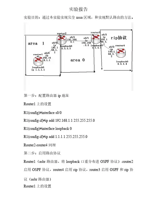
实验报告实验报告实验目的:通过本实验实现完全nssa 区域,和实现默认路由的方法。
第一步:配置路由器ip 地址地址Router1上的设置上的设置R1(config)#interface s0/0R1(config-if)#ip add 192.168.1.1 255.255.255.0R1(config)#interface loopback 0R1(config-if)#ip add 1.1.1.1 255.255.255.0Router2-router4同理同理第二步:启用路由协议第二步:启用路由协议Router1(asbr 路由器,将loopback 口重分布进OSPF 协议)-router2启用OSPF 协议,router4启用rip 协议,router3启用OSPF 和rip 协议(asbr 路由器)路由器)Router1上的设置上的设置R1(config)#router ospf 1R1(config-router)#network 192.168.1.0 0.0.0.255 area 1 R1(config)#router ospf 1R1(config-router)#redistribute connected subnetsR1(config-router)#area 1 nssaRouter2上的设置上的设置R2(config)#router ospf 1R2(config-router)#network 192.168.1.0 0.0.0.255 area 1 R2(config-router)#network 192.168.2.0 0.0.0.255 area 0 R2(config-router)#network 2.2.2.0 0.0.0.255 area 0R2(config-router)#area 1 nssaRouter3上的设置上的设置R3(config)#router ospf 1R3(config-router)#network 192.168.2.0 0.0.0.255 area 0 R3(config-router)#network 3.3.3.0 0.0.0.255 area 0R3(config)#router ripR3(config-router)#version 2R3(config-router)#network 192.168.3.0R3(config-router)#no auto-summaryRouter4上的设置上的设置R4(config)#router ripR4(config-router)#version 2R4(config-router)#network 192.168.3.0R4(config-router)#network 4.4.4.0R4(config-router)#no auto-summary第三步:设置路由重分布(在router3上设置)上设置)R3(config)#router ripR3(config-router)#redistribute ospf 1 metric 2R3(config)#router ospf 1R3(config-router)#redistribute rip subnets metric 1000第四步:查看路由表第四步:查看路由表Router1上的路由表上的路由表R1#show ip routeCodes: C - connected, S - static, R - RIP, M - mobile, B - BGPD - EIGRP , EX - EIGRP external, O - OSPF, IA - OSPF inter areaN1 - OSPF NSSA external type 1, N2 - OSPF NSSA external type 2E1 - OSPF external type 1, E2 - OSPF external type 2i - IS-IS, su - IS-IS summary, L1 - IS-IS level-1, L2 - IS-IS level-2ia - IS-IS inter area, * - candidate default, U - per-user static routeo - ODR, P - periodic downloaded static routeGateway of last resort is not set1.0.0.0/24 is subnetted, 1 subnetsC 1.1.1.0 is directly connected, Loopback02.0.0.0/32 is subnetted, 1 subnetsO IA 2.2.2.2 [110/65] via 192.168.1.2, 00:01:38, Serial0/03.0.0.0/32 is subnetted, 1 subnetsO IA 3.3.3.3 [110/129] via 192.168.1.2, 00:01:38, Serial0/0C 192.168.1.0/24 is directly connected, Serial0/0O IA 192.168.2.0/24 [110/128] via 192.168.1.2, 00:01:38, Serial0/0 Router2上的路由条目上的路由条目R2#show ip routeCodes: C - connected, S - static, R - RIP, M - mobile, B - BGPD - EIGRP, EX - EIGRP external, O - OSPF, IA - OSPF inter areaN1 - OSPF NSSA external type 1, N2 - OSPF NSSA external type 2E1 - OSPF external type 1, E2 - OSPF external type 2i - IS-IS, su - IS-IS summary, L1 - IS-IS level-1, L2 - IS-IS level-2ia - IS-IS inter area, * - candidate default, U - per-user staticrouteo - ODR, P - periodic downloaded static routeGateway of last resort is not set1.0.0.0/24 is subnetted, 1 subnetsO N2 1.1.1.0 [110/20] via 192.168.1.1, 00:00:06, Serial0/02.0.0.0/24 is subnetted, 1 subnetsC 2.2.2.0 is directly connected, Loopback03.0.0.0/32 is subnetted, 1 subnetsO 3.3.3.3 [110/65] via 192.168.2.2, 00:07:45, Serial0/14.0.0.0/24 is subnetted, 1 subnetsO E2 4.4.4.0 [110/1000] via 192.168.2.2, 00:00:06, Serial0/1C 192.168.1.0/24 is directly connected, Serial0/0C 192.168.2.0/24 is directly connected, Serial0/1O E2 192.168.3.0/24 [110/1000] via 192.168.2.2, 00:00:06, Serial0/1 Router4上的路由条目上的路由条目R4#show ip routeCodes: C - connected, S - static, R - RIP, M - mobile, B - BGPD - EIGRP, EX - EIGRP external, O - OSPF, IA - OSPF inter areaN1 - OSPF NSSA external type 1, N2 - OSPF NSSA externaltype 2E1 - OSPF external type 1, E2 - OSPF external type 2i - IS-IS, su - IS-IS summary, L1 - IS-IS level-1, L2 - IS-IS level-2ia - IS-IS inter area, * - candidate default, U - per-user static routeo - ODR, P - periodic downloaded static routeGateway of last resort is not set1.0.0.0/24 is subnetted, 1 subnetsR 1.1.1.0 [120/2] via 192.168.3.1, 00:00:15, Serial0/22.0.0.0/32 is subnetted, 1 subnetsR 2.2.2.2 [120/2] via 192.168.3.1, 00:00:15, Serial0/23.0.0.0/24 is subnetted, 1 subnetsR 3.3.3.0 [120/2] via 192.168.3.1, 00:00:15, Serial0/24.0.0.0/24 is subnetted, 1 subnetsC 4.4.4.0 is directly connected, Loopback0R 192.168.1.0/24 [120/2] via 192.168.3.1, 00:00:15, Serial0/2R 192.168.2.0/24 [120/2] via 192.168.3.1, 00:00:16, Serial0/2C 192.168.3.0/24 is directly connected, Serial0/2上验证第五步:在router1上验证R1#ping 192.168.3.2Type escape sequence to abort.Sending 5, 100-byte ICMP Echos to 192.168.3.2, timeout is 2 seconds: .....Success rate is 0 percent (0/5)在router2上配置,使之正常通信上配置,使之正常通信方法1Router2的设置的设置R2(config)#router ospf 1R2(config-router)#area 1 nssa no-summary在router1上查看上查看R1#show ip routeCodes: C - connected, S - static, R - RIP, M - mobile, B - BGPD - EIGRP, EX - EIGRP external, O - OSPF, IA - OSPF inter areaN1 - OSPF NSSA external type 1, N2 - OSPF NSSA external type 2E1 - OSPF external type 1, E2 - OSPF external type 2i - IS-IS, su - IS-IS summary, L1 - IS-IS level-1, L2 - IS-ISlevel-2ia - IS-IS inter area, * - candidate default, U - per-user static routeo - ODR, P - periodic downloaded static routeGateway of last resort is 192.168.1.2 to network 0.0.0.01.0.0.0/24 is subnetted, 1 subnetsC 1.1.1.0 is directly connected, Loopback0C 192.168.1.0/24 is directly connected, Serial0/0O*IA 0.0.0.0/0 [110/65] via 192.168.1.2, 00:00:07, Serial0/0验证是否正常通信验证是否正常通信R1#ping 192.168.3.2Type escape sequence to abort.Sending 5, 100-byte ICMP Echos to 192.168.3.2, timeout is 2 seconds:Success rate is 100 percent (5/5), round-trip min/avg/max = 784/1107/1440 ms通信成功通信成功方法2在router2上的配置上的配置R2(config)#router ospf 1R2(config-router)#area 1 nssa default-information-originate在router1上查看路由表上查看路由表R1#show ip routeCodes: C - connected, S - static, R - RIP, M - mobile, B - BGPD - EIGRP , EX - EIGRP external, O - OSPF, IA - OSPF inter areaN1 - OSPF NSSA external type 1, N2 - OSPF NSSA external type 2E1 - OSPF external type 1, E2 - OSPF external type 2i - IS-IS, su - IS-IS summary, L1 - IS-IS level-1, L2 - IS-IS level-2ia - IS-IS inter area, * - candidate default, U - per-user static routeo - ODR, P - periodic downloaded static routeGateway of last resort is 192.168.1.2 to network 0.0.0.01.0.0.0/24 is subnetted, 1 subnets C1.1.1.0 is directly connected, Loopback02.0.0.0/32 is subnetted, 1 subnetsO IA2.2.2.2 [110/65] via 192.168.1.2, 00:00:05, Serial0/03.0.0.0/32 is subnetted, 1 subnets O IA3.3.3.3 [110/129] via 192.168.1.2, 00:00:05, Serial0/0 C192.168.1.0/24 is directly connected, Serial0/0 O IA 192.168.2.0/24 [110/128] via 192.168.1.2, 00:00:05, Serial0/0 O*N2 0.0.0.0/0 [110/1] via 192.168.1.2, 00:00:05, Serial0/0验证是否正常通信验证是否正常通信R1#ping 192.168.3.2Type escape sequence to abort.Sending 5, 100-byte ICMP Echos to 192.168.3.2, timeout is 2 seconds:Success rate is 100 percent (5/5), round-trip min/avg/max = 784/1107/1440 ms方法3Router2上的设置上的设置R2(config-router)#area1 nssa default-information-originate no-summary查看router1上的路由表上的路由表R1#show ip routeCodes: C - connected, S - static, R - RIP, M - mobile, B - BGPD - EIGRP, EX - EIGRP external, O - OSPF, IA - OSPF inter areaN1 - OSPF NSSA external type 1, N2 - OSPF NSSA external type 2E1 - OSPF external type 1, E2 - OSPF external type 2i - IS-IS, su - IS-IS summary, L1 - IS-IS level-1, L2 - IS-IS level-2ia - IS-IS inter area, * - candidate default, U - per-user staticrouteo - ODR, P - periodic downloaded static routeGateway of last resort is 192.168.1.2 to network 0.0.0.01.0.0.0/24 is subnetted, 1 subnetsC 1.1.1.0 is directly connected, Loopback0C 192.168.1.0/24 is directly connected, Serial0/0O*IA 0.0.0.0/0 [110/65] via 192.168.1.2, 00:00:38, Serial0/0。
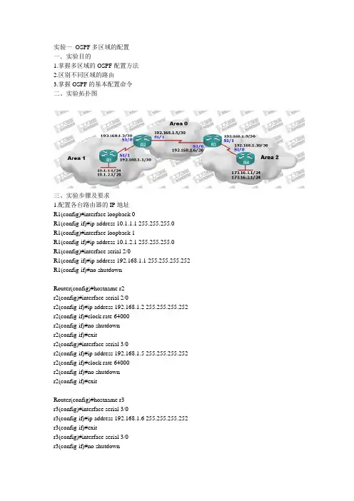
实验一OSPF多区域的配置一.实验目的1.掌握多区域的OSPF配置方法2.区别不同区域的路由3.掌握OSPF的基本配置命令二、实验拓扑图三、实验步骤及要求1.配置各台路由器的IP地址R1(config)#interface loopback 0R1(config-if)#ip address 10.1.1.1 255.255.255.0R1(config)#interface loopback 1R1(config-if)#ip address 10.1.2.1 255.255.255.0R1(config)#interface serial 2/0R1(config-if)#ip address 192.168.1.1 255.255.255.252 R1(config-if)#no shutdownRouter(config)#hostname r2r2(config)#interface serial 2/0r2(config-if)#ip address 192.168.1.2 255.255.255.252 r2(config-if)#clock rate 64000r2(config-if)#no shutdownr2(config-if)#exitr2(config)#interface serial 3/0r2(config-if)#ip address 192.168.1.5 255.255.255.252 r2(config-if)#clock rate 64000r2(config-if)#no shutdownr2(config-if)#exitRouter(config)#hostname r3r3(config)#interface serial 3/0r3(config-if)#ip address 192.168.1.6 255.255.255.252 r3(config-if)#exitr3(config)#interface serial 3/0r3(config-if)#no shutdownr3(config)#interface serial 2/0r3(config-if)#ip address 192.168.1.9 255.255.255.252r3(config-if)#clock rate 64000r3(config-if)#no shutdownRouter(config)#hostname r4r4(config)#interface serial 2/0r4(config-if)#ip address 192.168.1.10 255.255.255.252r4(config-if)#no shutdownr4(config-if)#exitr4(config)#interface loopback 0r4(config-if)#ip address 172.16.1.1 255.255.255.0r4(config-if)#exitr4(config)#interface loopback 1r4(config-if)#ip address 172.16.2.1 255.255.255.02.在r1上进行area1区域OSPF配置Router(config)#hostname r1r1(config)#router ospf 1r1(config-router)#network 10.1.2.0 0.0.0.255 area 1r1(config-router)#network 10.1.1.0 0.0.0.255 area 1r1(config-router)#network 192.168.1.0 0.0.0.3 area 1r1(config-router)#exit3.在r2上进行area1与area0的区域边界路由器(ABR)的OSPF配置r2(config)#router ospf 1r2(config-router)#network 192.168.1.0 0.0.0.3 area 1r2(config-router)#network 192.168.1.4 0.0.0.3 area 0r2(config-router)#exit4. 在r4上进行area2区域OSPF配置r4(config)#router ospf 1r4(config-router)#network 172.16.1.0 0.0.0.255 area 2r4(config-router)#network 172.16.2.0 0.0.0.255 area 2r4(config-router)#network 192.168.1.8 0.0.0.3 area 2r4(config-router)#exit在r3上进行area2与area0的区域边界路由器(ABR)的OSPF配置r3(config)#router ospf 1r3(config-router)#network 192.168.1.8 0.0.0.3 area 2r3(config-router)#network 192.168.1.4 0.0.0.3 area 0r3(config-router)#exit5. 在任一路由器上查看OSPF邻居表r2#show ip ospf neighborNeighbor ID Pri State Dead Time Address Interface 10.1.2.1 0 FULL/ - 00:00:38 192.168.1.1 Serial2/0 192.168.1.9 0 FULL/ - 00:00:39 192.168.1.6 Serial3/0R2路由器已经成功与r1和r3路由器建立邻居关系6.查看r1的路由表,观察其他区域的路由r1#show ip routeCodes: C - connected, S - static, I - IGRP, R - RIP, M - mobile, B - BGPD - EIGRP, EX - EIGRP external, O - OSPF, IA - OSPF inter areaN1 - OSPF NSSA external type 1, N2 - OSPF NSSA external type 2E1 - OSPF external type 1, E2 - OSPF external type 2, E - EGPi - IS-IS, L1 - IS-IS level-1, L2 - IS-IS level-2, ia - IS-IS inter area* - candidate default, U - per-user static route, o - ODRP - periodic downloaded static routeGateway of last resort is not set10.0.0.0/24 is subnetted, 2 subnetsC 10.1.1.0 is directly connected, Loopback0C 10.1.2.0 is directly connected, Loopback1172.16.0.0/32 is subnetted, 2 subnetsO IA 172.16.1.1 [110/2344] via 192.168.1.2, 00:00:05, Serial2/0O IA 172.16.2.1 [110/2344] via 192.168.1.2, 00:00:05, Serial2/0192.168.1.0/30 is subnetted, 3 subnetsC 192.168.1.0 is directly connected, Serial2/0O IA 192.168.1.4 [110/1562] via 192.168.1.2, 00:00:05, Serial2/0O IA 192.168.1.8 [110/2343] via 192.168.1.2, 00:00:05, Serial2/07.查看r1的OSPF链路状态数据库r1#show ip ospf databaseOSPF Router with ID (10.1.2.1) (Process ID 1)Router Link States (Area 1)Link ID ADV Router Age Seq# Checksum Link count 10.1.2.1 10.1.2.1 310 0x80000007 0x00463f 4192.168.1.5 192.168.1.5 310 0x80000006 0x00164a 2Summary Net Link States (Area 1)Link ID ADV Router Age Seq# Checksum192.168.1.4 192.168.1.5 845 0x80000001 0x00fe75192.168.1.8 192.168.1.5 518 0x80000002 0x0072ec172.16.1.1 192.168.1.5 518 0x80000003 0x00fe0f8.在r1上使用ping命令确认路由的有效性r1#ping 172.16.1.1Type escape sequence to abort.Sending 5, 100-byte ICMP Echos to 172.16.1.1, timeout is 2 seconds:!!!!!Success rate is 100 percent (5/5), round-trip min/avg/max = 78/87/94 ms9.查看r4的路由表和ospf的链路状态数据库r4#show ip routeCodes: C - connected, S - static, I - IGRP, R - RIP, M - mobile, B - BGPD - EIGRP, EX - EIGRP external, O - OSPF, IA - OSPF inter areaN1 - OSPF NSSA external type 1, N2 - OSPF NSSA external type 2E1 - OSPF external type 1, E2 - OSPF external type 2, E - EGPi - IS-IS, L1 - IS-IS level-1, L2 - IS-IS level-2, ia - IS-IS inter area* - candidate default, U - per-user static route, o - ODRP - periodic downloaded static routeGateway of last resort is not set10.0.0.0/32 is subnetted, 2 subnetsO IA 10.1.1.1 [110/2344] via 192.168.1.9, 00:23:31, Serial2/0O IA 10.1.2.1 [110/2344] via 192.168.1.9, 00:23:31, Serial2/0172.16.0.0/24 is subnetted, 2 subnetsC 172.16.1.0 is directly connected, Loopback0C 172.16.2.0 is directly connected, Loopback1192.168.1.0/30 is subnetted, 3 subnetsO IA 192.168.1.0 [110/2343] via 192.168.1.9, 00:23:41, Serial2/0O IA 192.168.1.4 [110/1562] via 192.168.1.9, 00:27:24, Serial2/0C 192.168.1.8 is directly connected, Serial2/0r4#show ip ospf databaseOSPF Router with ID (172.16.2.1) (Process ID 1)Router Link States (Area 2)Link ID ADV Router Age Seq# Checksum Link count 172.16.2.1 172.16.2.1 34 0x80000005 0x00feff 4192.168.1.9 192.168.1.9 14 0x80000004 0x00feff 2Summary Net Link States (Area 2)Link ID ADV Router Age Seq# Checksum192.168.1.0 192.168.1.9 1590 0x80000005 0x00a4bb10.1.1.1 192.168.1.9 1580 0x80000007 0x00d5e1 192.168.1.4 192.168.1.9 9 0x80000008 0x00f206。
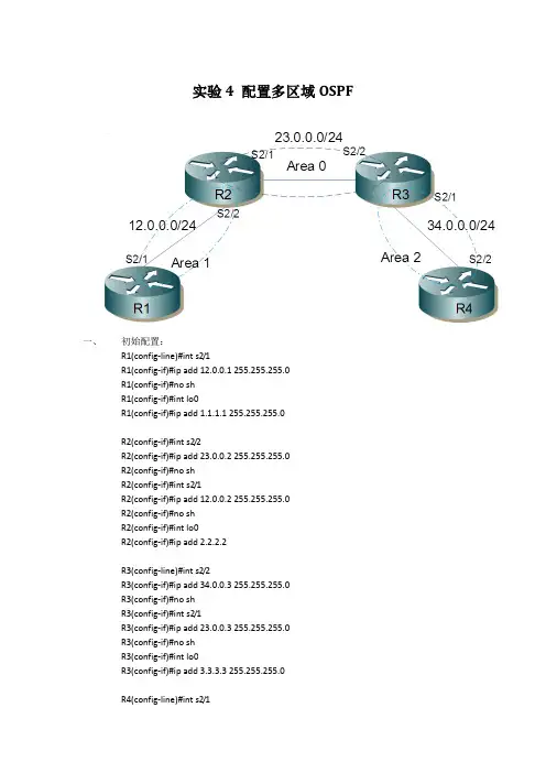
实验4 配置多区域OSPF一、初始配置:R1(config-line)#int s2/1R1(config-if)#ip add 12.0.0.1 255.255.255.0R1(config-if)#no shR1(config-if)#int lo0R1(config-if)#ip add 1.1.1.1 255.255.255.0R2(config-if)#int s2/2R2(config-if)#ip add 23.0.0.2 255.255.255.0R2(config-if)#no shR2(config-if)#int s2/1R2(config-if)#ip add 12.0.0.2 255.255.255.0R2(config-if)#no shR2(config-if)#int lo0R2(config-if)#ip add 2.2.2.2R3(config-line)#int s2/2R3(config-if)#ip add 34.0.0.3 255.255.255.0R3(config-if)#no shR3(config-if)#int s2/1R3(config-if)#ip add 23.0.0.3 255.255.255.0R3(config-if)#no shR3(config-if)#int lo0R3(config-if)#ip add 3.3.3.3 255.255.255.0R4(config-line)#int s2/1R4(config-if)#ip add 34.0.0.4 255.255.255.0R4(config-if)#no shR4(config-if)#int lo0R4(config-if)#ip add 4.4.4.4 255.255.255.0二、实验配置://配置R1R1(config-if)#router os 1R1(config-router)#network 12.0.0.1 255.255.255.255 area 1R1(config-router)#network 1.1.1.1 255.255.255.255 area 1//配置R2R2(config-if)#router os 1R2(config-router)#net 12.0.0.2 255.255.255.255 a 1R2(config-router)#net 23.0.0.2 255.255.255.255 a 0R2(config-router)#net 2.2.2.2 255.255.255.255 a 0//配置R3R3(config-if)#router os 1R3(config-router)#net 23.0.0.3 255.255.255.255 a 0R3(config-router)#net 34.0.0.3 255.255.255.255 a 2R3(config-router)#net 3.3.3.3 255.255.255.255 a 0//配置R4R4(config)#router os 1R4(config-router)#net 34.0.0.4 255.255.255.255 a 2R4(config-router)#net 4.4.4.4 255.255.255.255 a 2三、调试1.查看OSPF邻居//查看R1的OSPF邻居R1(config-router)#do sh ip os neNeighbor ID Pri State Dead Time Address Interface2.2.2.2 0 FULL/ - 00:00:39 12.0.0.2 Serial2/1//查看R2的OSPF邻居R2(config-router)#do sh ip os neNeighbor ID Pri State Dead Time Address Interface3.3.3.3 0 FULL/ - 00:00:32 23.0.0.3 Serial2/21.1.1.1 0 FULL/ - 00:00:30 12.0.0.1 Serial2/1//查看R3的OSPF邻居R3(config-router)#do sh ip os neNeighbor ID Pri State Dead Time Address Interface2.2.2.2 0 FULL/ - 00:00:36 23.0.0.2 Serial2/14.4.4.4 0 FULL/ - 00:00:31 34.0.0.4 Serial2/2//查看R4的OSPF邻居R4(config-router)#do sh ip os neNeighbor ID Pri State Dead Time Address Interface3.3.3.3 0 FULL/ - 00:00:33 34.0.0.3 Serial2/1 2.查看链路状态数据库//查看R1上的链路状态数据库R1(config-router)#do sh ip os daOSPF Router with ID (1.1.1.1) (Process ID 1)Router Link States (Area 1)Link ID ADV Router Age Seq# Checksum Link count1.1.1.1 1.1.1.1 762 0x80000003 0x00F46F 32.2.2.2 2.2.2.2 749 0x80000002 0x00561E 2Summary Net Link States (Area 1)Link ID ADV Router Age Seq# Checksum2.2.2.2 2.2.2.2 631 0x80000001 0x00FA313.3.3.3 2.2.2.2 641 0x80000001 0x004F984.4.4.4 2.2.2.2 669 0x80000001 0x00A3FF23.0.0.0 2.2.2.2 745 0x80000001 0x00A33A34.0.0.0 2.2.2.2 708 0x80000001 0x0096FB//查看R2上的链路状态数据库R2(config-router)#do sh ip os daOSPF Router with ID (2.2.2.2) (Process ID 1)Router Link States (Area 0)Link ID ADV Router Age Seq# Checksum Link count2.2.2.2 2.2.2.2 770 0x80000003 0x008EAD 33.3.3.3 3.3.3.3 782 0x80000003 0x002C07 3Summary Net Link States (Area 0)Link ID ADV Router Age Seq# Checksum1.1.1.12.2.2.2 885 0x80000001 0x00AB444.4.4.4 3.3.3.3 806 0x80000001 0x0003DC12.0.0.0 2.2.2.2 885 0x80000001 0x0033B534.0.0.0 3.3.3.3 844 0x80000001 0x00F5D8Router Link States (Area 1)Link ID ADV Router Age Seq# Checksum Link count1.1.1.1 1.1.1.1 899 0x80000003 0x00F46F 32.2.2.2 2.2.2.2 884 0x80000002 0x00561E 2Summary Net Link States (Area 1)Link ID ADV Router Age Seq# Checksum2.2.2.2 2.2.2.2 766 0x80000001 0x00FA313.3.3.3 2.2.2.2 778 0x80000001 0x004F984.4.4.4 2.2.2.2 806 0x80000001 0x00A3FF23.0.0.0 2.2.2.2 882 0x80000001 0x00A33A34.0.0.0 2.2.2.2 845 0x80000001 0x0096FB3.查看路由表//查看R1上的路由表R1(config-router)#do sh ip rouCodes: C - connected, S - static, R - RIP, M - mobile, B - BGPD - EIGRP, EX - EIGRP external, O - OSPF, IA - OSPF inter areaN1 - OSPF NSSA external type 1, N2 - OSPF NSSA external type 2E1 - OSPF external type 1, E2 - OSPF external type 2i - IS-IS, su - IS-IS summary, L1 - IS-IS level-1, L2 - IS-IS level-2ia - IS-IS inter area, * - candidate default, U - per-user static routeo - ODR, P - periodic downloaded static routeGateway of last resort is not set34.0.0.0/24 is subnetted, 1 subnetsO IA 34.0.0.0 [110/192] via 12.0.0.2, 00:16:01, Serial2/11.0.0.0/24 is subnetted, 1 subnetsC 1.1.1.0 is directly connected, Loopback02.0.0.0/32 is subnetted, 1 subnetsO IA 2.2.2.2 [110/65] via 12.0.0.2, 00:14:44, Serial2/13.0.0.0/32 is subnetted, 1 subnetsO IA 3.3.3.3 [110/129] via 12.0.0.2, 00:14:54, Serial2/14.0.0.0/32 is subnetted, 1 subnetsO IA 4.4.4.4 [110/193] via 12.0.0.2, 00:15:22, Serial2/123.0.0.0/24 is subnetted, 1 subnetsO IA 23.0.0.0 [110/128] via 12.0.0.2, 00:16:38, Serial2/112.0.0.0/24 is subnetted, 1 subnetsC 12.0.0.0 is directly connected, Serial2/1//查看R2上的路由表34.0.0.0/24 is subnetted, 1 subnetsO IA 34.0.0.0 [110/128] via 23.0.0.3, 00:16:09, Serial2/21.0.0.0/32 is subnetted, 1 subnetsO 1.1.1.1 [110/65] via 12.0.0.1, 00:18:03, Serial2/12.0.0.0/24 is subnetted, 1 subnetsC 2.2.2.0 is directly connected, Loopback03.0.0.0/32 is subnetted, 1 subnetsO 3.3.3.3 [110/65] via 23.0.0.3, 00:16:09, Serial2/24.0.0.0/32 is subnetted, 1 subnetsO IA 4.4.4.4 [110/129] via 23.0.0.3, 00:16:09, Serial2/223.0.0.0/24 is subnetted, 1 subnetsC 23.0.0.0 is directly connected, Serial2/212.0.0.0/24 is subnetted, 1 subnetsC 12.0.0.0 is directly connected, Serial2/1通过本实验,掌握了多区域OSPF的基本配置,应注意各非0区域必须与0区域相连,否则可能导致无法同步数据库,不能正常路由。
在思科模拟器中OSPF怎样设定思科模拟器怎么配置四个路由器四个区域OSPF100在思科模bai拟器中ospf设定的du步骤如下:zhi1、router1的dao配置版;配置环回口和int2/0的介面的ip地址和ospf的配置。
2、权router2的配置;配置环回口和int2/0的介面的ip地址和ospf的配置。
以及int2/0 的时脉频率。
3、router3的配置;配置环回口和int3/0的介面的ip地址和ospf 的配置。
以及int3/0 的时脉频率。
4、以router3为例,show??ip ospf inte***ce,此命令可以显示路由器的介面状态,如区域号、路由器的id、网路型别、介面成本。
5、以router 3为例。
通过show ?ip router命令,显示路由的情况,设定完成这样问题就解决了。
enable 进入特权复模式configuration terminal 进入配置模式router ospf xx(进位制程号,随意就一个bai标示)du 进入路由zhi模式***work x.x.x.x x.x.x.x area 0 宣告网路show ip ospf neighbor 检视daoospf邻居关系show ip route protocol ospf 检视ospf路由买本ospf的书看看,有点复杂思科模拟器怎么配置四个路由器四个区域ospf100把中间路由器的的四个介面的ip网段在ospf的程序下宣告到area 0区域。
把其他四个路由器连线中间路由器的埠的网段地址也宣告到area 0中。
剩下4个loopback介面的网段地址按图分别宣告到不同的area中就可以了这个只要做一个中心型的网路即可,中心是一个公共区域0,其他3个路由器其他介面连线交换机或pc机组成各个非骨干区域。
拓扑图如下:用思科模拟器怎么配置这个图多区域ospf ,求大神把中间路由器的的四个介面的ip网段在ospf的程序下宣告到area 0区域。
Juniper路由器配置OSPF本文介绍了在Juniper路由器里配置OSPF动态路由协议的方法,包括:配置单区域OSPF、配置多区域OSPF、配置Stub Area、配置OSPF Virtual Link、配置OSPF Router Interfaces、配置OSPF验证等,详细的操作步骤请查看以下内容。
1、配置单区域OSPF[edit]user@host# set protocols ospf area 0 interface ge-0/0/0INIT2wayExstartExchangeFULL[edit]user@host# show protocols ospfospf {are.0 {interface ge-0/0/0.0;}}2、配置多区域OSPF[edit]user@host# show protocols ospfospf {are.0 {interface ge-0/0/0.0;}}[edit]user@host# set protocols ospf area 1 interface at-0/1/1.100 [edit]user@host# show protocols ospfospf {are.0 {interface ge-0/0/0.0;}are.1 {interface at-0/1/1.100;}3、配置Stub Area[edit protocols ospf area area-id ]stub <default-metric metric> <(no-summaries | summaries)>; 配置a Not-So-Stubby Area[edit protocols ospf area area-id ]nssa {area-range network/mask-length <restrict>;default-lsa {default-metric metric;metric-type type;type-7;}(no-summaries | summaries);}4、配置OSPF Virtual Link使用virtual Link 连接防止环路。
OSPF 单区域配置实验题目: OSPF 单区域配置实验目的:理解协议、ospf 协议,掌握在单区域环境中配置ospf 路由协议,实现简单的ospf 配置实验设备及环境: 路由器RSR10、 路由器快速以太网口、 PC 机 实验拓扑图图17 OSPF 单区域配置实验拓扑图实验步骤1.在路由器上配置IP 地址RA#config tRA(config)# interface FastEthernet 0/0 //进入网口fa0/0RA(config-if)#ip address 192.168.20.1 255.255.255.252 //设置ip 地址RA(config)#interface Loopback 0 //进入内部回环接口RA(config-if)#ip address 192.168.30.9 255.255.255.248 //设置ip 地址RB#config tRB(config)# interface FastEthernet 0/0 //进入网口fa0/0RB(config-if)#ip address 192.168.20.2 255.255.255.252 //设置ip 地址RB(config)#interface FastEthernet 0/1 //进入网口fa0/1RB(config-if)#ip address 192.168.10.1 255.255.255.224 //设置F0/1 F0/0 F0/0 F0/0ip地址RC#config tRC(config)# interface FastEthernet 0/0 //进入网口fa0/0RC(config-if)#ip address 192.168.10.2 255.255.255.224 //设置ip地址RC(config)#interface Loopback 0 //进入内部回环接口RC(config-if)#ip address 192.168.10.33 255.255.255.240 //设置ip地址RC(config)#interface Loopback 1 //进入内部回环接口RC(config-if)#ip address 192.168.10.65 255.255.255.192 //设置ip地址2.配置OSPFRA(config)#router ospf 10 //进入ospf区域10配置模式RA(config-router)#network 192.168.30.8 0.0.0.7 area 0 //声明路由器直连网段RA(config-router)#network 192.168.20.0 0.0.0.3 area 0 //声明路由器直连网段RB(config)# router ospf 10 //进入ospf区域10配置模式RB(config-router)#network 192.168.10.0 0.0.0.31 area 0 //声明路由器直连网段RB(config-router)#network 192.168.20.0 0.0.0.3 area 0 //声明路由器直连网段RC(config)# router ospf 10 //进入ospf区域10配置模式RC(config-router)#network 192.168.10.0 0.0.0.31 area 0 //声明路由器直连网段RC(config-router)#network 192.168.10.32 0.0.0.15 area 0 //声明路由器直连网段RC(config-router)#network 192.168.10.64 0.0.0.63 area 0 //声明路由器直连网段配置OSPF多区域实验题目:OSPF多区域配置实验目的:理解协议、OSPF 协议,掌握在多区域环境中配置ospf路由协议,理解ospf层次型网络的特点实验设备及环境:路由器2621、路由器快速以太网接口、PC机实验基本配置:1.全局设置指定使用OSPF协议 router ospf process-id2.路由设置指定与该路由器相连的网络 network address wildcard-mask area area-id指定与该路由器相邻的节点地址 neighbor ip-address实验拓扑图:图18 配置OSPF多区域实验拓扑图实验步骤1.在路由器上配置IP地址。
华为路由器多区域。
SPf配置多区域。
SPf配置area© area51Ie“、”” 2.2.2.1 2.2.2.2 3・3・3・1 3・3・3・P GE(VM) GEMyl GEgfO1.1.1.1 ~ / AR2 AR3一、配置各个路由器的ip地址:ARl:<Huawei><Huawei>system-view [Huawei]sysname Rl 〃修改路由器名称为Rl [Rl]undo info-center enable[Rl]int IO 〃进入接口IooPbakO[Rl-LoopBackO]ip add 1.1.1.1 24[Rl-LoopBackOJint g0∕0∕0[Rl-GigabitEthernetO∕O∕O]ip address 2.2.2.1 24[Rl-GigabitEthernetO∕O∕O]quitAR2:<Huawei>sy<Huawei>system-view[Huawei]sysname R2[R2]undo info-center enable[R2]int g0∕0∕0[R2-GigabitEthernet0∕0∕0]ip add 2.2.2.2 24[R2-GigabitEthernet0∕0∕0]int gO/O/1[R2-GigabitEthernetO∕O∕l]ip add 3.3.3.1 24[R2-GigabitEthernetO∕O∕l]quitAR3:<Huawei>sy[Huawei]sysname R3[R3]undo info-center enable[R3]int gO/O/O[R3-GigabitEthernet0∕0∕0]i p add 33.3.2 24[R3-GigabitEthernet0∕0∕0]int IO[R3-LoopBackO]ip add 4.4.4.1 24[R3-LoopBackO]quit二、配置OSPf协议:loopbackΘ4.4.4.1ARI:[Ri][Rl]ospf 1[Rl-ospf-l]area 0 〃建立并进入区域0[Rl-ospf-l-area-0.0.0.0]net 1.1.1.0 0.0.0.255[Rl-ospf-l-area-0.0.0.0]net 2.2.2.0 0.0.0.255 〃向直连网段宣告[Rl-ospf-l-area-0.0.0.0]quit[Rl-ospf-l]quitAR2:[R2]ospf 1[R2-ospf-l]area 0 〃进入areaθ[R2-ospf-l-area-0.0.0,0]net 2.2.2.0 0.0.0.255 〃向网段2.2.2.0 宣告[R2-ospf-l-area-0.0.0.0]quit[R2-ospf-l]area 51 〃进入area51[R2-ospf-l-area-0.0.0.51]net 33.3.0 0.0.0.255 〃向网段3.33.0 宣告[R2-ospf-l-area-0.0.0.51]quit[R2-ospf-l]quitAR3:[R3]ospf 1[R3-ospf-l]area 51[R3-ospf-l-area-0.0.0.51]net 3.3.3.0 0.0.0.255[R3-ospf-l-area-0.0.0.51]net 4.4.4.0 0.0.0.255[R3-ospf-l-area-0.0.0.51]quit[R3-ospf-l]quit[R3]dis ip routing-table 〃查看路由器表同时查看其它路由器上的路由表,看是否完整。
OSPF(开放式最短路径优先协议)是一种基于链路状态的路由协议,用于实现大型的企业网络中的路由。
本文将介绍如何配置OSPF。
1. 配置OSPF进程
在每个运行OSPF的路由器上配置OSPF进程。
进入路由器的配置模式并输入以下命令:
Router(config)# router ospf process-id
将process-id替换为一个整数值,可以是任何数字,但它应该在整个网络中唯一。
2. 配置区域
将每个路由器分配到一个或多个区域中。
在路由器上,进入配置模式并输入以下命令:
Router(config-router)# area area-id
将area-id替换为一个数字,可以是任何数字,但应该在整个网络中唯一。
3. 配置网络
在每个路由器上,配置与OSPF连接的每个网络。
Router(config-router)# network network-address wildcard-mask area area-id
将network-address替换为网络地址,wildcard-mask替换为反掩码,area-id替换为路由器所在区域的ID。
4. 确认配置
输入以下命令以确认OSPF配置:
Router# show ip protocols
Router# show ip ospf neighbor
使用这些命令可以查看OSPF协议的状态,以及与其他OSPF路由器的领域关系。
以上是配置OSPF的基本步骤。
但在实际操作时,需要考虑到网络的规模和层级结构,以便更好地组织和管理网络。