思科、华为dhcp及中继代理配置实例
- 格式:doc
- 大小:44.50 KB
- 文档页数:8
华为⽹络实验-利⽤DHCP服务(中继⼝)⾃动获取IP⽬录实验原理第⼀步:客户端通过⼴播发送DHCP Discover 报⽂寻找服务器端第⼆步:服务器端通过单播发送DHCP Offer 报⽂向客户端提供IP地址等⽹络信息第三步:客户端通过⼴播DHCP Request 报⽂告知服务器端本地选择使⽤哪个IP地址第四步:服务器通过单播DHCP Ack报⽂告知客户端IP地址是合法可⽤的即客户端两次⼴播,服务器端两次单播实验⽬的通过DHCP服务(中继⼝)来⾃动获取IP具体操作1.SW1的命令1)进⼊系统界⾯并重命名为SW12)把e0/0/1⼝变为access⼝,同理e/0/0/2,e/0/0/3,e/0/0/4.3)把g0/0/1⼝变为trunk⼝2.R1的命令1)进⼊系统界⾯并重命名为R12)添加g/0/0/0和g/0/0/2的IP和⼦⽹掩码3)开通DHCP全局服务,添加单臂路由并让g/0/0/1成为中继⼝转到14.0.0.24)设置默认路由3.R2的命令1)进⼊系统界⾯并重命名为R2并添加g/0/0/2的IP和⼦⽹掩码,这边就不截图了,直接开始下⾯命令2)开始DHCP全局服务,添加g/0/0/1IP和⼦⽹掩码并让这个⼝也成为中继⼝转到14.0.0.23)添加3条静态路由4.R3的命令1)命名R2并添加⼝的IP和⼦⽹掩码2)开始DHCP服务,在接⼝处声明服务池3)第⼀个服务池R2那边的中继⼝(⽹络号、⼦⽹掩码、ip、dns)注:excluded-ip-address+IP ------排除IPstatic-bind ip-address+ip mac-address+mac地址 -----绑定ip和主机mac4)第⼆个服务池R1单臂路由的⼦接⼝5)第三个服务池R1单臂路由的另⼀个⼦接⼝6)设置⼀条静态路由即可(处于末梢端,并且是R2的直连路由)实验结果1)配置界⾯改为⾃动获取DHCP并抓包2)输⼊ipconfig /renew-----获取ip注:ipconfig /release----释放ip ⼀般不⽤同理,其他4台pc也能获取⾃⼰的ip,因为PC5我给它配了⼀个固定ip15.0.0.88并且与之mac绑定了3)全⽹互通(ping)实验总结DHCP服务的报⽂可以总结为两次客户端⼴播+两次服务器单播。

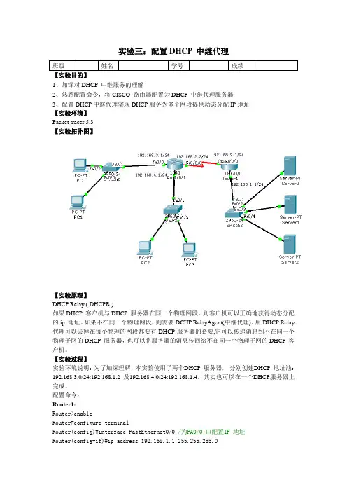
实验三:配置DHCP 中继代理班级姓名学号成绩【实验目的】1、加深对DHCP 中继服务的理解2、熟悉配置命令,将CISCO 路由器配置为DHCP 中继代理服务器3、配置DHCP中继代理实现DHCP服务为多个网段提供动态分配IP地址【实验环境】Packet tracer 5.3【实验拓扑图】【实验原理】DHCP Relay ( DHCPR )如果DHCP 客户机与DHCP 服务器在同一个物理网段,则客户机可以正确地获得动态分配的ip 地址。
如果不在同一个物理网段,则需要DCHP RelayAgent(中继代理)。
用DHCP Relay 代理可以去掉在每个物理的网段都要有DHCP服务器的必要,它可以传递消息到不在同一个物理子网的DHCP 服务器,也可以将服务器的消息传回给不在同一个物理子网的DHCP 客户机。
【实验过程】实验环境说明:为了加深理解,本实验使用了两个DHCP 服务器,分别创建DHCP 地址池:192.168.3.0/24:192.168.1.2 及192.168.4.0/24:192.168.1.4。
其实也可以在一个DHCP服务器上完成。
配置命令:Router1:Router>enableRouter#configure terminalRouter(config)#interface FastEthernet0/0 /为FA0/0 口配置IP 地址Router(config-if)#ip address 192.168.1.1 255.255.255.0Router(config-if)#no shutdownRouter(config-if)#exitRouter(config)#interface S0/0/0 /为S0/0/0 口配置IP 地址Router(config-if)#ip address 192.168.2.1 255.255.255.0Router(config-if)#clock rate 64000 /为S0/0/0 口配置串行链路时钟Router(config-if)#no shutdownRouter(config-if)#exitRouter(config)#router eigrp 10 /启用EIGRP 协议Router(config-router)#network 192.168.1.0 /将192.168.1.0 加入作用域Router(config-router)#network 192.168.2.0Router(config-router)#auto-summary /启用自动汇总Router0:Router>enableRouter#configure terminalRouter(config)#interface FastEthernet0/0Router(config-if)#ip address 192.168.3.1 255.255.255.0Router(config-if)#no shutdownRouter(config-if)#exitRouter(config)#interface FastEthernet0/1Router(config-if)#no shutdownRouter(config-if)#ip address 192.168.4.1 255.255.255.0Router(config-if)#no shutdownRouter(config-if)#exitRouter(config)#interface S0/0/0Router(config-if)#ip address 192.168.2.2 255.255.255.0Router(config)#router eigrp 10Router(config-router)#network 192.168.3.0Router(config-router)#network 192.168.2.0Router(config-router)#network 192.168.4.0Router(config-router)#auto-summaryRouter(config-router)#exitRouter(config)#int fa 0/0Router(config-if)#ip helper-address 192.168.1.4 /配置DHCP 中继代理。
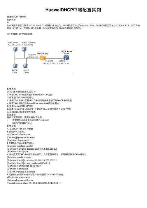
HuaweiDHCP中继配置实例配置DHCP中继⽰例组⽹需求如DHCP服务器应当配置⼀个10.100.0.0/16⽹段的IP地址池,DNS服务器地址为10.100.1.2/16,NetBIOS服务器地址10.100.1.3/16,出⼝⽹关地址10.100.1.4,并且DHCP服务器上应当配置有到10.100.0.0/16⽹段的路由。
图1 配置DHCP中继组⽹图配置思路DHCP服务器的配置思路如下:1. 使能DHCP中继服务器S-switch的DHCP功能2. 配置接⼝VLANIF2的地址3. 在接⼝VLANIF1配置IP以及中继地址并使能接⼝的DHCP中继功能4. 配置DHCP服务器Router到10.100.0.0/16⽹段的路由5. 使能Router的DHCP功能6. 配置Router的接⼝GE0/0/1下的客户端从全局地址池中获取IP地址7. 在Router上配置全局地址池数据准备完成此配置举例,需要准备以下数据:· 要实现DHCP中继功能的接⼝的IP地址· DHCP服务器的地址配置步骤1. 在DHCP中继上进⾏配置# 使能DHCP服务。
<Quidway> system-view[Quidway] sysname S-switch[S-switch] dhcp enable# 配置接⼝VLANIF2的地址。
[S-switch] interface vlanif 2[S-switch-Vlanif2] ip address 202.40.1.1 255.255.0.0[S-switch-Vlanif2] quit# 进⼊要实现DHCP中继功能的接⼝,为其配置IP地址、⼦⽹掩码和DHCP中继地址。
[S-switch] interface vlanif 1[S-switch-Vlanif1] ip address 10.100.1.1 255.255.0.0[S-switch-Vlanif1] ip relay address 202.40.1.2[S-switch-Vlanif1] dhcp select relay[S-switch-Vlanif1] quit2. 在DHCP服务器上进⾏配置# 配置Router到S-switch与客户端相连接⼝VLANIF1的路由。

华为路由器dhcp简单配置实例session 1 DHCP的工作原理DHCP(Dynamic Host Configuration Protocol,动态主机配置协议)是一个局域网的网络协议,使用UDP协议工作,主要有两个用途:给内部网络或网络服务供应商自动分配IP地址,给用户或者内部网络管理员作为对所有计算机作中央管理的手段,在RFC 2131中有详细的描述。
DHCP有3个端口,其中UDP67和UDP68为正常的DHCP 服务端口,分别作为DHCP Server和DHCP Client的服务端口;546号端口用于DHCPv6 Client,而不用于DHCPv4,是为DHCP failover服务,这是需要特别开启的服务,DHCP failover是用来做“双机热备”的。
DHCP协议采用UDP作为传输协议,主机发送请求消息到DHCP服务器的67号端口,DHCP服务器回应应答消息给主机的68号端口,DHCP的IP地址自动获取工作原理及详细步骤如下:1、DHCP Client以广播的方式发出DHCP Discover报文。
2、所有的DHCP Server都能够接收到DHCP Client发送的DHCP Discover报文,所有的DHCP Server都会给出响应,向DHCP Client发送一个DHCP Offer报文。
DHCP Offer报文中“Your(Client) IP Address”字段就是DHCP Server 能够提供给DHCP Client使用的IP地址,且DHCP Server会将自己的IP地址放在“option”字段中以便DHCP Client 区分不同的DHCP Server。
DHCP Server在发出此报文后会存在一个已分配IP地址的纪录。
3、DHCP Client只能处理其中的一个DHCP Offer报文,一般的原则是DHCP Client处理最先收到的DHCP Offer报文。
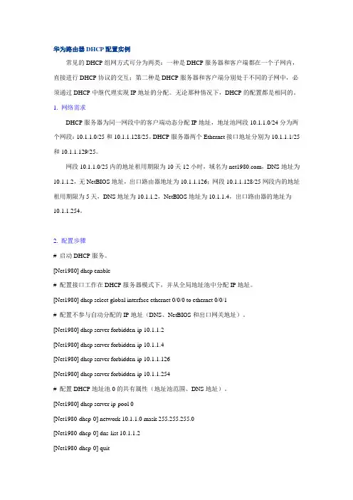
华为路由器DHCP配置实例常见的DHCP组网方式可分为两类:一种是DHCP服务器和客户端都在一个子网内,直接进行DHCP协议的交互;第二种是DHCP服务器和客户端分别处于不同的子网中,必须通过DHCP中继代理实现IP地址的分配。
无论那种情况下,DHCP的配置都是相同的。
1. 网络需求DHCP服务器为同一网段中的客户端动态分配IP地址,地址池网段10.1.1.0/24分为两个网段:10.1.1.0/25和10.1.1.128/25。
DHCP服务器两个Ethernet接口地址分别为10.1.1.1/25和10.1.1.129/25。
网段10.1.1.0/25内的地址租用期限为10天12小时,域名为,DNS地址为10.1.1.2,无NetBIOS地址,出口路由器地址为10.1.1.126;网段10.1.1.128/25网段内的地址租用期限为5天,DNS地址为10.1.1.2,NetBIOS地址为10.1.1.4,出口路由器的地址为10.1.1.254。
2. 配置步骤# 启动DHCP服务。
[Net1980] dhcp enable# 配置接口工作在DHCP服务器模式下,并从全局地址池中分配IP地址。
[Net1980] dhcp select global interface ethernet 0/0/0 to ethernet 0/0/1# 配置不参与自动分配的IP地址(DNS、NetBIOS和出口网关地址)。
[Net1980] dhcp server forbidden-ip 10.1.1.2[Net1980] dhcp server forbidden-ip 10.1.1.4[Net1980] dhcp server forbidden-ip 10.1.1.126[Net1980] dhcp server forbidden-ip 10.1.1.254# 配置DHCP地址池0的共有属性(地址池范围、DNS地址)。
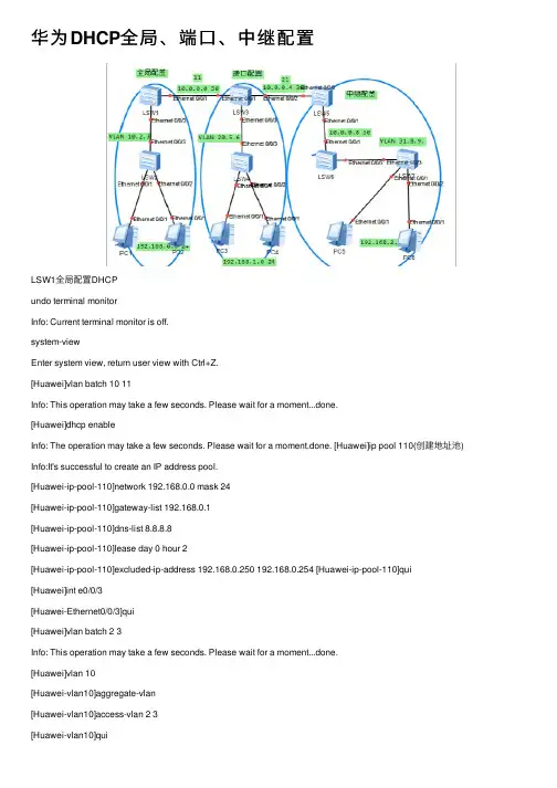
华为DHCP全局、端⼝、中继配置LSW1全局配置DHCPundo terminal monitorInfo: Current terminal monitor is off.system-viewEnter system view, return user view with Ctrl+Z.[Huawei]vlan batch 10 11Info: This operation may take a few seconds. Please wait for a moment...done.[Huawei]dhcp enableInfo: The operation may take a few seconds. Please wait for a moment.done. [Huawei]ip pool 110(创建地址池) Info:It's successful to create an IP address pool.[Huawei-ip-pool-110]network 192.168.0.0 mask 24[Huawei-ip-pool-110]gateway-list 192.168.0.1[Huawei-ip-pool-110]dns-list 8.8.8.8[Huawei-ip-pool-110]lease day 0 hour 2[Huawei-ip-pool-110]excluded-ip-address 192.168.0.250 192.168.0.254 [Huawei-ip-pool-110]qui [Huawei]int e0/0/3[Huawei-Ethernet0/0/3]qui[Huawei]vlan batch 2 3Info: This operation may take a few seconds. Please wait for a moment...done.[Huawei]vlan 10[Huawei-vlan10]aggregate-vlan[Huawei-vlan10]access-vlan 2 3[Huawei]int vlanif 10[Huawei-Vlanif10]ip address 192.168.0.1 24[Huawei-Vlanif10]dhcp select global[Huawei-Vlanif10]qui[Huawei]int vlanif 11[Huawei-Vlanif11]ip add 10.0.0.1 30[Huawei-Vlanif11]qui[Huawei]int e0/0/3[Huawei-Ethernet0/0/3]port link-type trunk[Huawei-Ethernet0/0/3]port trunk allow-pass vlan 2 3[Huawei-Ethernet0/0/3]int e0/0/1[Huawei-Ethernet0/0/1]port link-type access[Huawei-Ethernet0/0/1]port default vlan 11[Huawei-Ethernet0/0/1]qui[Huawei]ip route-static 192.168.1.0 24 10.0.0.2[Huawei]ip route-static 192.168.2.0 24 10.0.0.2[Huawei]ip route-static 10.0.0.4 30 10.0.0.2[Huawei]ip route-static 10.0.0.8 30 10.0.0.2[Huawei]LSW2undo terminal monitorInfo: Current terminal monitor is off.system-viewEnter system view, return user view with Ctrl+Z.[Huawei]vlan batch 2 3Info: This operation may take a few seconds. Please wait for a moment...done. [Huawei]int e0/0/1[Huawei-Ethernet0/0/1]port link-type access[Huawei-Ethernet0/0/1]port default vlan 2[Huawei-Ethernet0/0/1]int e0/0/2[Huawei-Ethernet0/0/2]port link-type access[Huawei-Ethernet0/0/2]port default vlan 3[Huawei-Ethernet0/0/2]int e0/0/3[Huawei-Ethernet0/0/3]port link-type trunk[Huawei-Ethernet0/0/3] User interface con0 is availableLSW3端⼝配置DHCPundo terminal monitorInfo: Current terminal monitor is off.sysEnter system view, return user view with Ctrl+Z.[Huawei]vlan batch 11 20 21 5 6Info: This operation may take a few seconds. Please wait for a moment...done.[Huawei]int vlanif 11[Huawei-Vlanif11]ip add 10.0.0.2 30[Huawei-Vlanif11]int vlanif 21[Huawei-Vlanif21]ip add 10.0.0.5 30[Huawei-Vlanif21]qui[Huawei]vlan 20[Huawei-vlan20]aggregate-vlan[Huawei-vlan20]access-vlan 5 6[Huawei-vlan20]qui[Huawei]dhcp enableInfo: The operation may take a few seconds. Please wait for a moment.done. [Huawei]int vlanif 20 [Huawei-Vlanif20]ip add 192.168.1.1 24[Huawei-Vlanif20]dhcp select interface[Huawei-Vlanif20]dhcp server dns-list 8.8.8.8[Huawei-Vlanif20]dhcp server lease day 0 hour 3[Huawei-Vlanif20]dhcp server excluded-ip-address 192.168.1.250192.168.1.254[Huawei-Vlanif20]qui[Huawei]int e0/0/1[Huawei-Ethernet0/0/1]port link-type access[Huawei-Ethernet0/0/1]port default vlan 11[Huawei-Ethernet0/0/1]int e0/0/2[Huawei-Ethernet0/0/2]port link-type access[Huawei-Ethernet0/0/2]port default vlan 21[Huawei-Ethernet0/0/2]int e0/0/3[Huawei-Ethernet0/0/3]qui[Huawei]ip route-static 192.168.1.0 24 10.0.0.1[Huawei]undo ip route-static 192.168.1.0 24 10.0.0.1[Huawei]ip route-static 192.168.0.0 24 10.0.0.1[Huawei]ip route-static 192.168.2.0 24 10.0.0.6[Huawei]ip route-static 10.0.0.8 24 10.0.0.6Info: The destination address and mask of the configured static route mismatched , and the static route 10.0.0.0/24 was generated.[Huawei]ip route-static 10.0.0.8 30 10.0.0.6[Huawei] User interface con0 is availableLSW4Huawei>undo terminal monitorInfo: Current terminal monitor is off.sysEnter system view, return user view with Ctrl+Z.[Huawei]vlan batch 5 6Info: This operation may take a few seconds. Please wait for a moment...done. [Huawei]int e0/0/1[Huawei-Ethernet0/0/1]port link-type access[Huawei-Ethernet0/0/1]port default vlan 5[Huawei-Ethernet0/0/1]int e0/0/2[Huawei-Ethernet0/0/2]port link-type access[Huawei-Ethernet0/0/2]port default vlan 6[Huawei-Ethernet0/0/2]int e0/0/3[Huawei-Ethernet0/0/3]port link-type trunk[Huawei-Ethernet0/0/3]port trunk allow-pass vlan 5 6[Huawei-Ethernet0/0/3] User interface con0 is availableLSW5中继配置DHCPundo ter mInfo: Current terminal monitor is off.sysEnter system view, return user view with Ctrl+Z.[Huawei]vlan batch 21 30[Huawei][Huawei]dhcp enableInfo: The operation may take a few seconds. Please wait for a moment.done. [Huawei]int vlanif 21[Huawei-Vlanif21]ip add 10.0.0.6 30[Huawei-Vlanif21]int vlanif 30[Huawei-Vlanif30]ip add 10.0.0.9 30[Huawei-Vlanif30]qui[Huawei]int vlanif 30[Huawei-Vlanif30][Huawei-Vlanif30] dhcp select global[Huawei-Vlanif30]qui[Huawei]ip pool 300Info:It's successful to create an IP address pool. [Huawei-ip-pool-300]network 192.168.2.0 mask 24 [Huawei-ip-pool-300]gateway-list 192.168.2.1[Huawei-ip-pool-300]dns-list 8.8.8.8[Huawei-ip-pool-300]lease day 0 hour 2[Huawei-ip-pool-300]qui[Huawei]int e0/0/1[Huawei-Ethernet0/0/1]port link-type access[Huawei-Ethernet0/0/1]port defaul vlan 30[Huawei-Ethernet0/0/1]int e0/0/2[Huawei-Ethernet0/0/2]port link-type access[Huawei-Ethernet0/0/2]port defaul vlan 21[Huawei-Ethernet0/0/2] User interface con0 is available [Huawei]ip route-static 192.168.0.0 24 10.0.0.5 [Huawei]ip route-static 192.168.1.0 24 10.0.0.5 [Huawei]ip route-static 10.0.0.0 30 10.0.0.5[Huawei]ip route-static 192.168.2.0 24 10.0.0.10LSW6undo terminal monitorInfo: Current terminal monitor is off.langu chineseChange language mode, confirm? [Y/N] y提⽰:改变语⾔模式成功。
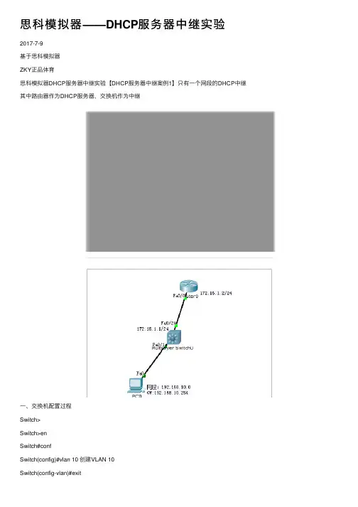
思科模拟器——DHCP服务器中继实验2017-7-9基于思科模拟器ZKY正品体育思科模拟器DHCP服务器中继实验【DHCP服务器中继案例1】只有⼀个⽹段的DHCP中继其中路由器作为DHCP服务器,交换机作为中继⼀、交换机配置过程Switch>Switch>enSwitch#confSwitch(config)#vlan 10 创建VLAN 10Switch(config-vlan)#exitSwitch(config)#int vlan 10Switch(config-if)#ip address 192.168.10.254 255.255.255.0 为VLAN 10配置地址Switch(config-if)#no shut 开启虚拟接⼝Switch(config-if)#exitSwitch(config)#int fa0/1Switch(config-if)#switchport access vlan 10 将fa0/1加⼊vlan 10Switch(config-if)#exitSwitch(config)#int fa0/24Switch(config-if)#no switchport 将交换⼝转换为路由⼝Switch(config-if)#ip adSwitch(config-if)#ip address 172.16.1.1 255.255.255.0Switch(config-if)#no shutSwitch(config-if)#exSwitch(config)#ip route 0.0.0.0 0.0.0.0 172.16.1.2Switch(config-if)#Switch(config-if)#exitSwitch(config)#int vlan 10Switch(config-if)#ip ?access-group Specify access control for packetsaddress Set the IP address of an interfacehello-interval Configures IP-EIGRP hello intervalhelper-address Specify a destination address for UDP broadcasts nat NAT interface commandsospf OSPF interface commandsproxy-arp Enable proxy ARPsplit-horizon Perform split horizonsummary-address Perform address summarizationSwitch(config-if)#ip helpSwitch(config-if)#ip helper-address 172.16.1.2Switch(config-if)#endSwitch#%SYS-5-CONFIG_I: Configured from console by consoleSwitch#sh ip routeCodes: C - connected, S - static, I - IGRP, R - RIP, M - mobile, B - BGPD - EIGRP, EX - EIGRP external, O - OSPF, IA - OSPF inter areaN1 - OSPF NSSA external type 1, N2 - OSPF NSSA external type 2E1 - OSPF external type 1, E2 - OSPF external type 2, E - EGPi - IS-IS, L1 - IS-IS level-1, L2 - IS-IS level-2, ia - IS-IS inter area* - candidate default, U - per-user static route, o - ODRP - periodic downloaded static routeGateway of last resort is 172.16.1.2 to network 0.0.0.0172.16.0.0/24 is subnetted, 1 subnetsC 172.16.1.0 is directly connected, FastEthernet0/24C 192.168.10.0/24 is directly connected, Vlan10S* 0.0.0.0/0 [1/0] via 172.16.1.2Switch#confConfiguring from terminal, memory, or network [terminal]?Enter configuration commands, one per line. End with CNTL/Z. Switch(config)#ip routingSwitch(config)#endSwitch#%SYS-5-CONFIG_I: Configured from console by consoleSwitch#wrBuilding configuration...⼆、路由器配置过程Router>enRouter#confRouter(config)#int f0/0Router(config-if)#ip address 172.16.1.2 255.255.255.0Router(config-if)#exitRouter(config)#ip dhcp ?excluded-address Prevent DHCP from assigning certain addressespool Configure DHCP address poolsRouter(config)#ip dhcp excluded-address 192.168.10.254 排除地址,避免客户端获得此IP地址产⽣冲突Router(config)#ip dhcp pool vlan10 (创建地址池vlan10)Router(dhcp-config)#? (通过?可以知道DHCP服务器可以配置哪些选项)default-router Default routersdns-server Set name serverexit Exit from DHCP pool configuration modenetwork Network number and maskno Negate a command or set its defaultsoption Raw DHCP optionsRouter(dhcp-config)#default-router 192.168.10.254 (为客户端配置默认⽹关)Router(dhcp-config)#dns-server 192.168.10.254 (为客户端配置DNS)Router(dhcp-config)#netRouter(dhcp-config)#network 192.168.10.0 255.255.255.0 (客户端所在⽹络及掩码)Router(dhcp-config)#end Router(config)#ip route 0.0.0.0 0.0.0.0 172.16.1.1Router(config)#int fa0/0Router(config-if)#no shut【DHCP服务器中继案例2】有多个⽹段的DHCP中继⼀、交换机配置过程Switch>enSwitch#conf tEnter configuration commands, one per line. End with CNTL/Z.1.创建vlan 10,vlan20,vlan 30Switch(config)#vlan 10Switch(config-vlan)#vlan 20Switch(config-vlan)#vlan 30Switch(config-vlan)#2.为3个vlan创建相应的IP地址,并在vlan中创建中继,指向DHCP服务器地址Switch(config)#interface vlan 10Switch(config-if)#ip address 192.168.10.254 255.255.255.0Switch(config-if)#ip helper-address 172.16.1.2Switch(config)#interface vlan 20Switch(config-if)#ip address 192.168.20.254 255.255.255.0Switch(config-if)#ip helper-address 172.16.1.2Switch(config-if)#exitSwitch(config)#interface vlan 30Switch(config-if)#ip address 10.0.0.1 255.0.0.0Switch(config-if)#ip helper-address 172.16.1.23.将fa0/1,fa0/11,fa0/21分别加⼊vlan 10,vlan 20,vlan 30 Switch(config)#interface fastEthernet 0/1Switch(config-if)#switchport access vlan 10Switch(config)#interface fastEthernet 0/11Switch(config-if)#switchport access vlan 20Switch(config-if)#exitSwitch(config)#interface fastEthernet 0/21Switch(config-if)#switchport access vlan 30Switch(config-if)#Switch(config-if)#4.将fa0/24设置为路由⼝,并设置IP地址Switch(config)#interface fastEthernet 0/24Switch(config-if)#no switchportSwitch(config-if)#ip address 172.16.1.1 255.255.255.252 Switch(config-if)#5.设置默认路由,指向下⼀跳地址(即路由器接⼝地址)Switch(config-if)#exitSwitch(config)#ip route 0.0.0.0 0.0.0.0 172.16.1.2Switch(config)#6.交换机开启路由功能(总是会忘记这个,忘记了N次了)Switch(config)#ip routing7.保存配置Switch(config)#exitSwitch#%SYS-5-CONFIG_I: Configured from console by console Switch#wrBuilding configuration...[OK]Switch#⼆、路由器配置过程1.为路由器接⼝fa0/0配置IP地址,并开启接⼝Router>enRouter#conf tRouter(config)#interface fastEthernet 0/0Router(config-if)#ip address 172.16.1.2 255.255.255.252Router(config-if)#no shutdown (路由器默认情况下端⼝是禁⽤的,所以要开启,⽽交换机默认情况下端⼝是开启的,所以不需要敲此条命令)Router(config-if)#2.添加排除地址,避免客户端获得如下地址,产⽣IP地址冲突。
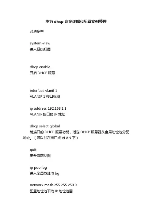
华为dhcp命令详解和配置案例整理必选配置system-view进入系统视图dhcp enable开启DHCP服务interface vlanif 1VLANIF 1 接口视图ip address 192.168.1.1VLANIF接口的IP地址dhcp select global能接口的DHCP服务功能,指定DHCP服务器从全局地址池分配地址。
(可以加在接口或VLAN下)quit离开当前视图ip pool bg进入全局地址池bgnetwork mask 255.255.250.0配置地址池下的IP地址范围gateway-list 192.168.1.1DHCP的网关可选配置domain-name XXX配置分配给DHCP客户端的DNS域名后缀(可选中的可选)dns-list 202.106.0.20 8.8.4.4配置DNS主和备lease day 1 hour 1 minute 1配置IP地址租期,此配置为一天一小时一分钟,默认为一天,unlimited为无限excluded-ip-address 192.168.1.100 192.168.1.254excluded-ip-address 192.168.1.1配置地址池中不参与自动分配的IP地址,多次执行该命令,可以配置多个不参与自动分配的IP地址段。
static-bind ip-address 172.16.35.253 mac-address 28d2-4469-5a55当一个用户需要固定的IP地址时,可以将地址池中没有在使用的IP地址与用户的MAC地址绑定。
DHCP中继当客户端与DHCP服务器不在同一网段时,通过在DHCP中继设备转发客户端到DHCP服务器的请求。
dhcp enable开启DHCP功能interface vlanif 1VLANIF 1 接口视图ip address 192.168.1.1VLANIF接口的IP地址dhcp select relay启动VLANIF接口的DHCP中继功能。
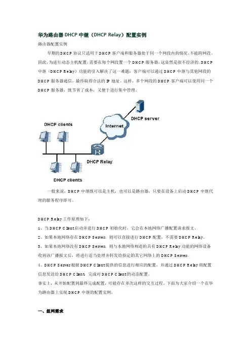
华为路由器DHCP中继(DHCP Relay)配置实例路由器配置实例早期的DHCP协议只适用于DHCP客户端和服务器处于同一个网段内的情况,不能跨网段。
因此,为进行动态主机配置,需要在每个网段置一个DHCP服务器,这显然是很不经济的。
DHCP 中继(DHCP Relay)功能的引入解决了这一难题:客户端可以通过DHCP中继与其他网段的DHCP服务器通信,最终取得合法的IP地址。
这样,多个网段的DHCP客户端可以使用同一个DHCP服务器,既节省了成本,又便于进行集中管理。
一般来说,DHCP中继既可以是主机,也可以是路由器,只要在设备上启动DHCP中继代理的服务程序即可。
DHCP Relay工作原理如下:1、当DHCP Client启动并进行DHCP初始化时,它会在本地网络广播配置请求报文。
2、如果本地网络存在DHCP Server,则可以直接进行DHCP配置,不需要DHCP Relay。
3、如果本地网络没有DHCP Server,则与本地网络相连的具有DHCP Relay功能的网络设备收到该广播报文后,将进行适当处理并转发给指定的其它网络上的DHCP Server。
4、DHCP Server根据DHCP Client提供的信息进行相应的配置,并通过DHCP Relay将配置信息发送给DHCP Client,完成对DHCP Client的动态配置。
事实上,从开始配置到最终完成配置,可能存在多次这样的交互过程。
下面为大家介绍一个在华为路由器上实现DHCP中继的配置实例。
一、组网需求如下图,DHCP客户端所在的网段为10.100.0.0/16,而DHCP服务器所在的网段为202.40.0.0/16。
需要通过带DHCP中继功能的路由设备中继DHCP报文,使得DHCP客户端可以从DHCP服务器上申请到IP地址等相关配置信息。
DHCP服务器应当配置一个10.100.0.0/16网段的IP地址池,DNS服务器地址为10.100.1.2/16,NetBIOS服务器地址10.100.1.3/16,出口网关地址10.100.1.4,并且DHCP 服务器上应当配置有到10.100.0.0/16网段的路由。

DHCP中继实验(cisco)最近看到大家经常由于DHCP的问题犯愁,为了让大家更明白的了解DHCP并且会配置,特此发这个贴相信大家认证看完对DHCP就会了如指掌1.配置DHCP Server(1)开启DHCP 功能r2(config)#service dhcp(2)配置DHCP 地址池r2(config)#ip dhcp poolccie1 地址池名为ccie1r2(dhcp-config)#network 10.1.1.0 255.255.255.0 可供客户端使用的地址段r2(dhcp-config)#default-router10.1.1.1 网关r2(dhcp-config)#dns-server 10.1.1.1 10.1.1.2 DNSr2(dhcp-config)#lease 1 11 租期为1 天1 小时1 分(默认为一天)r2(config)#ip dhcp poolccie2 地址池名为ccie1r2(dhcp-config)#network 20.1.1.0 255.255.255.0 可供客户端使用的地址段r2(dhcp-config)#default-router20.1.1.1 网关r2(dhcp-config)#dns-server 20.1.1.1 20.1.1.2 DNSr2(dhcp-config)#lease 1 11 租期为1 天1 小时1 分(默认一天)(3)去掉不提供给客户端的地址注:因为某些IP 地址不希望提供给客户端,比如网关地址,所以我们要将这些地址从地址池中移除,这样服务器就不会将这些地址发给客户端使用。
r2(config)#ip dhcp excluded-address10.1.1.1 10.1.1.10 移除10.1.1.1 到10.1.1.10r2(config)#ip dhcp excluded-address网段的地址发给客户,而不会错把20.1.1.0/24 网段的地址发给客户呢。
思科、华为dhcp及中继代理配置实例一、思科配置实例*****************网络环境:一台3550EMI交换机,划分三个vlan,vlan2 为服务器所在网络,命名为server,IP地址段为192.168.2.0,子网掩码:255.255.255.0,网关:192.168.2.1,域服务器为windows 2000 advance server,同时兼作DNS服务器,IP地址为192.168.2.10。
vlan3为客户机1所在网络,IP地址段为192.168.3. 0,子网掩码:255.255.255.0,网关:192.168.3.1命名为work01vlan4为客户机2所在网络,命名为wo rk02,IP地址段为192.168.4.0,子网掩码:255.255.255.0,网关:192.168.4.13550作DHCP服务器,端口1-8划到VLAN 2,端口9-16划分到VLAN 3,端口17-24划分到VLAN 4DHCP服务器实现功能:各VLAN保留2-10的IP地址不分配置,例如:192.168.2.0的网段,保留192.168.2.2至192.168.2.10的IP地址段不分配.安全要求:VLAN 3和VLAN 4 不允许互相访问,但都可以访问服务器所在的VLAN 2,默认访问控制列表的规则是拒绝所有包。
配置命令及步骤如下:第一步:创建VLANSwitch>enSwitch#Vlan DatabaseSwitch(Vlan)>Vlan 2 Name serverSwitch(Vlan)>Vlan 3 Name work01Switch(vlan)>Vlan 4 Name work02第二步:设置VLAN IP地址Switch#Config TSwitch(Config)>Int Vlan 2Switch(Config-vlan)Ip Address 192.168.2.1 255.255.255.0Switch(Config-vlan)No ShutSwitch(Config-vlan)>Int Vlan 3Switch(Config-vlan)Ip Address 192.168.3.1 255.255.255.0Switch(Config-vlan)No ShutSwitch(Config-vlan)>Int Vlan 4Switch(Config-vlan)Ip Address 192.168.4.1 255.255.255.0Switch(Config-vlan)No ShutSwitch(Config-vlan)Exit/*注意:由于此时没有将端口分配置到VLAN2,3,4,所以各VLAN会DOWN掉,待将端口分配到各VLAN后,VLAN 会起来*/第三步:设置端口全局参数Switch(Config)Interface Range Fa 0/1 - 24Switch(Config-if-range)Switchport Mode AccessSwitch(Config-if-range)Spanning-tree Portfast第四步:将端口添加到VLAN2,3,4中/*将端口1-8添加到VLAN 2*/Switch(Config)Interface Range Fa 0/1 - 8Switch(Config-if-range)Switchport Access Vlan 2/*将端口9-16添加到VLAN 3*/Switch(Config)Interface Range Fa 0/9 - 16Switch(Config-if-range)Switchport Access Vlan 3/*将端口17-24添加到VLAN 4*/Switch(Config)Interface Range Fa 0/17 - 24Switch(Config-if-range)Switchport Access Vlan 4Switch(Config-if-range)Exit/*经过这一步后,各VLAN会起来*/第五步:配置3550作为DHCP服务器/*VLAN 2可用地址池和相应参数的配置,有几个VLAN要设几个地址池*/Switch(Config)Ip Dhcp Pool Test01/*设置可分配的子网*/Switch(Config-pool)Network 192.168.2.0 255.255.255.0/*设置DNS服务器*/Switch(Config-pool)Dns-server 192.168.2.10/*设置该子网的网关*/Switch(Config-pool)Default-router 192.168.2.1/*配置VLAN 3所用的地址池和相应参数*/Switch(Config)Ip Dhcp Pool Test02Switch(Config-pool)Network 192.168.3.0 255.255.255.0Switch(Config-pool)Dns-server 192.168.2.10Switch(Config-pool)Default-router 192.168.3.1/*配置VLAN 4所用的地址池和相应参数*/Switch(Config)Ip Dhcp Pool Test03Switch(Config-pool)Network 192.168.4.0 255.255.255.0Switch(Config-pool)Dns-server 192.168.2.10Switch(Config-pool)Default-router 192.168.4.1第六步:设置DHCP保留不分配的地址Switch(Config)Ip Dhcp Excluded-address 192.168.2.2 192.168.2.10Switch(Config)Ip Dhcp Excluded-address 192.168.3.2 192.168.3.10Switch(Config)Ip Dhcp Excluded-address 192.168.4.2 192.168.4.10第七步:启用路由/*路由启用后,各VLAN间主机可互相访问*/Switch(Config)Ip Routing第八步:配置访问控制列表Switch(Config)access-list 103 permit ip 192.168.2.0 0.0.0.255 192.168.3.0 0.0.0.255 Switch(Config)access-list 103 permit ip 192.168.3.0 0.0.0.255 192.168.2.0 0.0.0.255 Switch(Config)access-list 103 permit udp any any eq bootpcSwitch(Config)access-list 103 permit udp any any eq tftpSwitch(Config)access-list 103 permit udp any eq bootpc anySwitch(Config)access-list 103 permit udp any eq tftp anySwitch(Config)access-list 104 permit ip 192.168.2.0 0.0.0.255 192.168.4.0 0.0.0.255 Switch(Config)access-list 104 permit ip 192.168.4.0 0.0.0.255 192.168.2.0 0.0.0.255 Switch(Config)access-list 104 permit udp any eq tftp anySwitch(Config)access-list 104 permit udp any eq bootpc anySwitch(Config)access-list 104 permit udp any eq bootpc anySwitch(Config)access-list 104 permit udp any eq tftp any第九步:应用访问控制列表/*将访问控制列表应用到VLAN 3和VLAN 4,VLAN 2不需要*/Switch(Config)Int Vlan 3Switch(Config-vlan)ip access-group 103 outSwitch(Config-vlan)Int Vlan 4Switch(Config-vlan)ip access-group 104 out第十步:结束并保存配置Switch(Config-vlan)EndSwitch#Copy Run Start**********************************************中继配置实例网络环境:一台3550EMI交换机,划分三个vlan,vlan2 为服务器所在网络,命名为server,IP地址段为192.168.2.0,子网掩码:255.255.255.0,网关:192.168.2.1,域服务器为windows 2000 advance server,同时兼作DHCP服务器,DNS服务器,IP地址为192.168.2.10,vlan3为客户机1所在网络,IP地址段为192.168.3.0,子网掩码:255.255.255.0,网关:192.168.3.1命名为work01, vlan4 为客户机2所在网络,命名为work02,IP地址段为192.168.4.0,子网掩码:255.255.255.0,网关:192.168.4.1.3550上端口1-8划到VLAN 2,端口9-16划分到VLAN 3,端口17-24划分到VLAN 4.配置命令及步骤如下:第一步:创建VLAN:Switch>Vlan DatabaseSwitch(Vlan)>Vlan 2 Name serverSwitch(Vlan)>Vlan 3 Name work01Switch(vlan)>Vlan 4 Name work02第二步:启用DHCP中继代理:/*关键一步,若缺少以下两条命令,在VLAN中使用“IP HELPER-ADDRESS DHCP 服务器地址”指定DHCP服务器,客户机仍然不能获得IP地址*/Switch>EnableSwitch#Config tSwitch(Config)Service DhcpSwitch(Config)Ip Dhcp Relay Information Option第三步:设置VLAN IP地址:Switch(Config)>Int Vlan 2Switch(Config-vlan)Ip Address 192.168.2.1 255.255.255.0Switch(Config-vlan)No ShutSwitch(Config-vlan)>Int Vlan 3Switch(Config-vlan)Ip Address 192.168.3.1 255.255.255.0Switch(Config-vlan)No ShutSwitch(Config-vlan)>Int Vlan 4Switch(Config-vlan)Ip Address 192.168.4.1 255.255.255.0Switch(Config-vlan)No ShutSwitch(Config-vlan)Exit/*注意:由于此时没有将端口分配置到VLAN2,3,4,所以各VLAN会DOWN掉,待将端口分配到各VLAN后,VLAN会起来*/第四步:设置端口全局参数Switch(Config)Interface Range Fa 0/1 - 24Switch(Config-if-range)Switchport Mode AccessSwitch(Config-if-range)Spanning-tree Portfast第五步:将端口添加到VLAN2,3,4中/*将端口1-8添加到VLAN 2*/Switch(Config)Interface Range Fa 0/1 - 8Switch(Config-if-range)Switchport Access Vlan 2/*将端口9-16添加到VLAN 3*/Switch(Config)Interface Range Fa 0/9 - 16Switch(Config-if-range)Switchport Access Vlan 3/*将端口17-24添加到VLAN 4*/Switch(Config)Interface Range Fa 0/17 - 24Switch(Config-if-range)Switchport Access Vlan 4Switch(Config-if-range)Exit/*经过这一步后,各VLAN会起来*/第六步:在VLAN3和4中设定DHCP服务器地址/*VLAN 2中不须指定DHCP服务器地址*/Switch(Config)Int Vlan 3Switch(Config-vlan)Ip Helper-address 192.168.2.10Switch(Config)Int Vlan 4Switch(Config-vlan)Ip Helper-address 192.168.2.10第七步:启用路由/*路由启用后,各VLAN间主机可互相访问,若需进一步控制访问权限,则需应用到访问控制列表*/Switch(Config)Ip Routing第八步:结束并保存配置Switch(Config-vlan)EndSwitch#Copy Run Start以上测试并获通过,感谢所有给予我帮助的人,感谢TERU,麦子提供的访问控制列表.**************************二、华为配置实例**************************DHCP 服务器典型配置举例常见的DHCP组网方式可分为两类:一种是DHCP服务器和客户端在同一个子网内,直接进行DHCP 报文的交互;另一种是DHCP 服务器和客户端处于不同的子网中,必须通过DHCP 中继代理实现IP 地址的分配。
配置DHCP中继示例本举例介绍DHCP中继的配置过程。
组网需求如图1,DHCP客户端所在的网段为20.20.20.0/24,而DHCP服务器所在的网段为100.10.10.0/24。
需要通过带DHCP Relay功能的Switch中继DHCP报文,使得DHCP客户端可以从DHCP服务器上申请到IP地址等相关配置信息。
DHCP服务器应当配置一个20.20.20.0/24网段的IP地址池,并且DHCP服务器到20.20.20.0/24网段路由可达。
图1 配置DHCP Relay组网图配置思路DHCP服务器的配置思路如下:1.创建DHCP服务器组并为服务器组添加DHCP服务器2.在VLANIF接口下使能DHCP Relay功能3.为VLANIF接口绑定指定的DHCP服务器组数据准备完成此配置举例,需要准备以下数据:∙DHCP服务器组的组名∙DHCP服务器组中的DHCP服务器IP地址∙启动DHCP Relay功能的接口编号及接口的IP地址操作步骤1.创建DHCP服务器组并为服务器组添加DHCP服务器。
# 创建DHCP服务器组。
<Quidway> system-view[Quidway] dhcp server group dhcpgroup1# 为DHCP服务器组添加DHCP服务器。
[Quidway-dhcp-server-group-dhcpgroup1] dhcp-server 100.10.10.1[Quidway-dhcp-server-group-dhcpgroup1] dhcp-server 100.10.10.2[Quidway-dhcp-server-group-dhcpgroup1] quit2.在VLANIF接口下使能DHCP Relay功能。
# 创建VLAN并将GE1/0/1接口加入到VLAN中。
[Quidway] vlan 100[Quidway-Vlan100] quit[Quidway] interface gigabitethernet 1/0/1[Quidway-GigabitEthernet1/0/1] port link-type access[Quidway-GigabitEthernet1/0/1] port default vlan 100[Quidway-GigabitEthernet1/0/1] quit# 使能全局DHCP功能,并使能VLANIF接口下DHCP Relay功能。
DHCP和中继配置方法
实验环境:GNS3 0.8.3.1版本,加载路由器IOS。
VPCS模拟PC
实验目的:学会使用DHCP中继给不同网段的主机分配IP地址。
R1是DHCP服务器,配置如下
1.先给端口配置ip地址
2.开启rip协议
3.配置地址池test1 test2
配置地址池test1
配置地址池范围
配置默认网关
配置DNS
还可以增加一条命令,排除一部分ip地址范围
意思是不分配192.168.1.100~192.168.1.200之间的IP地址,
不分配192.168.2.100~192.168.2.200之间的IP地址
4.默认DHCP服务器是开启的,也可以手动开启一下
R2上面的配置
过程同上,重复1~2步
配好IP地址以后,C2如果要想从R1获得IP地址,那么需要在R2的F0/1接口上(即C2所处网络的网关上配置中继)
验证:
C1上开启DHCP
C1已经获取了IP地址和,默认网管。
C2上开启DHCP
C2已经获取了IP地址和,默认网管。
一、拓扑图:二:配置:LSW1:sysname SW1#vlan batch 100 200#dhcp server group 1dhcp-server 23.1.1.2 0#interface Vlanif100ip address 1.1.1.2 255.255.255.0 #interface Vlanif200ip address 200.1.1.1 255.255.255.0 dhcp select relaydhcp relay server-select 1#interface GigabitEthernet0/0/1port link-type accessport default vlan 100#interface GigabitEthernet0/0/10port link-type accessport default vlan 200#ospf 1area 0.0.0.0 network 0.0.0.0 255.255.255.255R1:interface GigabitEthernet0/0/0ip address 12.1.1.1 255.255.255.0#interface GigabitEthernet0/0/1ip address 1.1.1.1 255.255.255.0#ospf 1area 0.0.0.0network 0.0.0.0 255.255.255.255R2:interface GigabitEthernet0/0/0ip address 12.1.1.2 255.255.255.0#interface GigabitEthernet0/0/1ip address 23.1.1.1 255.255.255.0#ospf 1area 0.0.0.0network 0.0.0.0 255.255.255.255LSW3(DHCP SERVER 服务器):dhcp enable#ip pool 200gateway-list 200.1.1.1network 200.1.1.0 mask 255.255.255.0excluded-ip-address 200.1.1.10 200.1.1.15dns-list 6.6.6.6#interface Vlanif100ip address 23.1.1.2 255.255.255.0dhcp select global#interface MEth0/0/1#interface GigabitEthernet0/0/1port link-type accessport default vlan 100#ospf 1area 0.0.0.0network 0.0.0.0 255.255.255.255三、测试:PC>ipconfig /releaseIP ConfigurationLink local IPv6 address...........: fe80::5689:98ff:fe25:6c1 IPv6 address......................: :: / 128IPv6 gateway......................: ::IPv4 address......................: 0.0.0.0Subnet mask.......................: 0.0.0.0 Gateway...........................: 0.0.0.0Physical address..................: 54-89-98-25-06-C1DNS server........................:PC>ipconfig /renewIP ConfigurationLink local IPv6 address...........: fe80::5689:98ff:fe25:6c1 IPv6 address......................: :: / 128IPv6 gateway......................: ::IPv4 address......................: 200.1.1.254 Subnet mask.......................: 255.255.255.0 Gateway...........................: 200.1.1.1 Physical address..................: 54-89-98-25-06-C1 DNS server........................: 6.6.6.6PC>ping 23.1.1.2Ping 23.1.1.2: 32 data bytes, Press Ctrl_C to break From 23.1.1.2: bytes=32 seq=1 ttl=252 time=93 ms From 23.1.1.2: bytes=32 seq=2 ttl=252 time=125 ms From 23.1.1.2: bytes=32 seq=3 ttl=252 time=109 ms From 23.1.1.2: bytes=32 seq=4 ttl=252 time=125 ms From 23.1.1.2: bytes=32 seq=5 ttl=252 time=78 ms--- 23.1.1.2 ping statistics ---5 packet(s) transmitted5 packet(s) received0.00% packet lossround-trip min/avg/max = 78/106/125 ms四、命令:display ip pool (服务器看地址利用率)display dhcp relay all (看中继配的相关信息)display dhcp server group。
华为三层交换机(5328)DHCP中继应用配置实例之前有人提出华为交换机关于DHCP中继配置方面的问题,我做了一个简单的测试,将测试结果分享给大家。
测试拓扑结构:sys #进入系统视图sysname dhcptest #设备重命名dhcp enable #启用DHCP功能Vlan 2 #创建vlan 2port GigabitEthernet 0/0/1 to 0/0/10 #批量添加端口quit #退出接口视图Vlan 5 #创建vlan 5port GigabitEthernet 0/0/11 to 0/0/20 #批量添加端口quit #退出接接口视图interface vlanif 2 #进入VLANIF 接口视图ip address 192.168.1.1 24 #增加VLANIF 接口的IP地址dhcp select relay #通过中继分配IP地址quit #退出接接口视图interface vlanif 5 #进入VLANIF 接口视图ip address 192.168.5.1 24 #配置VLANIF 接口的IP地址ip relay address 192.168.1.5 #增加VLANIF 接口的IP 中继地址dhcp select relay #通过中继分配IP地址quit #退出接口视图System-view #进入系统视图ip relay address 192.168.1.5 vlan 2 #配置DHCP服务器地址和所属vlan---结束检查配置结果查看DHCP 中继的相关统计信息display dhcp relay statistics查看接口的DHCP 中继地址配置display dhcp relay address vlan vlan-id通过以上正确配置后,将测试笔记本插入相应的vlan内,即可获得正确网段地址。
华为交换机怎么配置DHCP中继?交换机的中继配置⽅法
华为交换机在使⽤的时候,很多情况下我们需要在三层交换机上配置⼀下DHCP中继服务,⽤以为下⾯的客户机提供DHCP中继服务,就是说三层交换机上可以为DHCP端⼝转发数据到指定的DHCP服务器上;⽽不会因为是跨VLAN就导致客户机获取不到DHCP分配的IP地址,下⾯我们就来看看详细的教程。
1、请先确保你的电脑和华为交换机连接成功
2、进⼊管理视图
<Quidway> system-view
3、接着dhcp enable 开启交换机的DHCP服务
4、接着进⼊虚拟vlan 视图
[Quidway]interfaceVlanif 100
5、配置⼀个IP地址
[Quidway-Vlanif100] ip address 192.168.104.253 255.255.255.0
6、然后开始dhcp中继功能
[Quidway-Vlanif100]dhcpselect relay
7、配置DHCP服务器IP地址
[Quidway-Vlanif100]iprelay address 10.10.100.171
8、到此华为交换机的DHCP中继功能就配置完成了记得要save保存配置以上就是交换机的中继配置⽅法,希望⼤家喜欢,请继续关注。
思科、华为dhcp及中继代理配置实例交换技术 2008-01-22 09:24 阅读468 评论0字号:大中小*****************一、思科配置实例*****************网络环境:一台3550EMI交换机,划分三个vlan,vlan2 为服务器所在网络,命名为serv er,IP地址段为192.168.2.0,子网掩码:255.255.255.0,网关:192.168.2.1,域服务器为windows 2000 advance server,同时兼作DNS服务器,IP地址为192.168.2.10。
vlan3为客户机1所在网络,IP地址段为192.168.3. 0,子网掩码:255.255.255.0,网关:192.168.3.1命名为work01vlan4为客户机2所在网络,命名为wo rk02,IP地址段为192.168.4.0,子网掩码:2 55.255.255.0,网关:192.168.4.13550作DHCP服务器,端口1-8划到VLAN 2,端口9-16划分到VLAN 3,端口17-2 4划分到VLAN 4DHCP服务器实现功能:各VLAN保留2-10的IP地址不分配置,例如:192.168.2.0的网段,保留192.168.2.2至192.168.2.10的IP地址段不分配.安全要求:VLAN 3和VLAN 4 不允许互相访问,但都可以访问服务器所在的VLAN 2,默认访问控制列表的规则是拒绝所有包。
配置命令及步骤如下:第一步:创建VLANSwitch>enSwitch#Vlan DatabaseSwitch(Vlan)>Vlan 2 Name serverSwitch(Vlan)>Vlan 3 Name work01Switch(vlan)>Vlan 4 Name work02第二步:设置VLAN IP地址Switch#Config TSwitch(Config)>Int Vlan 2Switch(Config-vlan)Ip Address 192.168.2.1 255.255.255.0Switch(Config-vlan)No ShutSwitch(Config-vlan)>Int Vlan 3Switch(Config-vlan)Ip Address 192.168.3.1 255.255.255.0Switch(Config-vlan)No ShutSwitch(Config-vlan)>Int Vlan 4Switch(Config-vlan)Ip Address 192.168.4.1 255.255.255.0Switch(Config-vlan)No ShutSwitch(Config-vlan)Exit/*注意:由于此时没有将端口分配置到VLAN2,3,4,所以各VLAN会DOWN掉,待将端口分配到各VLAN后,VLAN 会起来*/第三步:设置端口全局参数Switch(Config)Interface Range Fa 0/1 - 24Switch(Config-if-range)Switchport Mode AccessSwitch(Config-if-range)Spanning-tree Portfast第四步:将端口添加到VLAN2,3,4中/*将端口1-8添加到VLAN 2*/Switch(Config)Interface Range Fa 0/1 - 8Switch(Config-if-range)Switchport Access Vlan 2/*将端口9-16添加到VLAN 3*/Switch(Config)Interface Range Fa 0/9 - 16Switch(Config-if-range)Switchport Access Vlan 3/*将端口17-24添加到VLAN 4*/Switch(Config)Interface Range Fa 0/17 - 24Switch(Config-if-range)Switchport Access Vlan 4Switch(Config-if-range)Exit/*经过这一步后,各VLAN会起来*/第五步:配置3550作为DHCP服务器/*VLAN 2可用地址池和相应参数的配置,有几个VLAN要设几个地址池*/Switch(Config)Ip Dhcp Pool Test01/*设置可分配的子网*/Switch(Config-pool)Network 192.168.2.0 255.255.255.0/*设置DNS服务器*/Switch(Config-pool)Dns-server 192.168.2.10/*设置该子网的网关*/Switch(Config-pool)Default-router 192.168.2.1/*配置VLAN 3所用的地址池和相应参数*/Switch(Config)Ip Dhcp Pool Test02Switch(Config-pool)Network 192.168.3.0 255.255.255.0Switch(Config-pool)Dns-server 192.168.2.10Switch(Config-pool)Default-router 192.168.3.1/*配置VLAN 4所用的地址池和相应参数*/Switch(Config)Ip Dhcp Pool Test03Switch(Config-pool)Network 192.168.4.0 255.255.255.0Switch(Config-pool)Dns-server 192.168.2.10Switch(Config-pool)Default-router 192.168.4.1第六步:设置DHCP保留不分配的地址Switch(Config)Ip Dhcp Excluded-address 192.168.2.2 192.168.2.10Switch(Config)Ip Dhcp Excluded-address 192.168.3.2 192.168.3.10Switch(Config)Ip Dhcp Excluded-address 192.168.4.2 192.168.4.10第七步:启用路由/*路由启用后,各VLAN间主机可互相访问*/Switch(Config)Ip Routing第八步:配置访问控制列表Switch(Config)access-list 103 permit ip 192.168.2.0 0.0.0.255 192.168.3.0 0.0.0.2 55Switch(Config)access-list 103 permit ip 192.168.3.0 0.0.0.255 192.168.2.0 0.0.0.2 55Switch(Config)access-list 103 permit udp any any eq bootpcSwitch(Config)access-list 103 permit udp any any eq tftpSwitch(Config)access-list 103 permit udp any eq bootpc anySwitch(Config)access-list 103 permit udp any eq tftp anySwitch(Config)access-list 104 permit ip 192.168.2.0 0.0.0.255 192.168.4.0 0.0.0.2 55Switch(Config)access-list 104 permit ip 192.168.4.0 0.0.0.255 192.168.2.0 0.0.0.2 55Switch(Config)access-list 104 permit udp any eq tftp anySwitch(Config)access-list 104 permit udp any eq bootpc anySwitch(Config)access-list 104 permit udp any eq bootpc anySwitch(Config)access-list 104 permit udp any eq tftp any第九步:应用访问控制列表/*将访问控制列表应用到VLAN 3和VLAN 4,VLAN 2不需要*/Switch(Config)Int Vlan 3Switch(Config-vlan)ip access-group 103 outSwitch(Config-vlan)Int Vlan 4Switch(Config-vlan)ip access-group 104 out第十步:结束并保存配置Switch(Config-vlan)EndSwitch#Copy Run Start**********************************************中继配置实例网络环境:一台3550EMI交换机,划分三个vlan,vlan2 为服务器所在网络,命名为s erver,IP地址段为192.168.2.0,子网掩码:255.255.255.0,网关:192.168.2.1,域服务器为wind ows 2000 advance server,同时兼作DHCP服务器,DNS服务器,IP地址为192.168.2. 10,vlan3为客户机1所在网络,IP地址段为192.168.3.0,子网掩码:255.255.255.0,网关:19 2.168.3.1命名为work01, vlan4 为客户机2所在网络,命名为work02,IP地址段为192.168.4.0,子网掩码:255.255.255.0,网关:192.168.4.1.3550上端口1-8划到VLAN 2,端口9-16划分到VLAN 3,端口17-24划分到VLAN 4.配置命令及步骤如下:第一步:创建VLAN:Switch>Vlan DatabaseSwitch(Vlan)>Vlan 2 Name serverSwitch(Vlan)>Vlan 3 Name work01Switch(vlan)>Vlan 4 Name work02第二步:启用DHCP中继代理:/*关键一步,若缺少以下两条命令,在VLAN中使用“IP HELPER-ADDRESS DHCP 服务器地址”指定DHCP服务器,客户机仍然不能获得IP地址*/Switch>EnableSwitch#Config tSwitch(Config)Service DhcpSwitch(Config)Ip Dhcp Relay Information Option第三步:设置VLAN IP地址:Switch(Config)>Int Vlan 2Switch(Config-vlan)Ip Address 192.168.2.1 255.255.255.0Switch(Config-vlan)No ShutSwitch(Config-vlan)>Int Vlan 3Switch(Config-vlan)Ip Address 192.168.3.1 255.255.255.0Switch(Config-vlan)No ShutSwitch(Config-vlan)>Int Vlan 4Switch(Config-vlan)Ip Address 192.168.4.1 255.255.255.0Switch(Config-vlan)No ShutSwitch(Config-vlan)Exit/*注意:由于此时没有将端口分配置到VLAN2,3,4,所以各VLAN会DOWN掉,待将端口分配到各VLAN后,VLAN会起来*/第四步:设置端口全局参数Switch(Config)Interface Range Fa 0/1 - 24Switch(Config-if-range)Switchport Mode AccessSwitch(Config-if-range)Spanning-tree Portfast第五步:将端口添加到VLAN2,3,4中/*将端口1-8添加到VLAN 2*/Switch(Config)Interface Range Fa 0/1 - 8Switch(Config-if-range)Switchport Access Vlan 2/*将端口9-16添加到VLAN 3*/Switch(Config)Interface Range Fa 0/9 - 16Switch(Config-if-range)Switchport Access Vlan 3/*将端口17-24添加到VLAN 4*/Switch(Config)Interface Range Fa 0/17 - 24Switch(Config-if-range)Switchport Access Vlan 4Switch(Config-if-range)Exit/*经过这一步后,各VLAN会起来*/第六步:在VLAN3和4中设定DHCP服务器地址/*VLAN 2中不须指定DHCP服务器地址*/Switch(Config)Int Vlan 3Switch(Config-vlan)Ip Helper-address 192.168.2.10Switch(Config)Int Vlan 4Switch(Config-vlan)Ip Helper-address 192.168.2.10第七步:启用路由/*路由启用后,各VLAN间主机可互相访问,若需进一步控制访问权限,则需应用到访问控制列表*/Switch(Config)Ip Routing第八步:结束并保存配置Switch(Config-vlan)EndSwitch#Copy Run Start以上测试并获通过,感谢所有给予我帮助的人,感谢TERU,麦子提供的访问控制列表.**************************二、华为配置实例**************************DHCP 服务器典型配置举例常见的DHCP组网方式可分为两类:一种是DHCP服务器和客户端在同一个子网内,直接进行DHCP 报文的交互;另一种是DHCP 服务器和客户端处于不同的子网中,必须通过DHCP 中继代理实现IP 地址的分配。