T6-SCR泰夕电压调整器说明书
- 格式:pdf
- 大小:2.17 MB
- 文档页数:14
目录安全及注意事项 (I)第一章H系列三相功率控制器的作用及特点 (1)1.1 作用 (1)1.2 特点 (1)第二章产品信息 (3)2.1 型号定义 (3)2.2 铭牌 (3)2.3 产品规格 (4)2.4 技术参数 (4)2.5 缩略语 (5)第三章安装及配线 (6)3.1 开箱检查 (6)3.2 使用条件 (6)3.3 安装 (7)3.4 电气配线 (7)3.5 基本接线原理图 (8)3.6 端子说明 (9)第四章显示及操作说明 (10)4.1 监控界面显示信息说明 (11)4.2 按键功能说明 (11)4.3 操作举例说明 (12)4.4 菜单 (12)4.5 控制参数A (13)4.6 显示参数B (13)4.7 保护参数C (13)4.7 保护参数C (14)4.8 高级参数D (14)第五章功率控制器功能介绍 (15)5.1 功能介绍 (15)5.2 功能参数表 (22)5.3 参数说明 (23)5.4 举例说明 (32)第六章故障处理及保养维护 (35)6.1 故障处理 (35)6.2 保养维护 (35)第七章通信说明 (37)7.1 通讯数据读写 (37)7.2 协议内容 (37)7.3 总线结构 (37)7.4 通讯帧结构 (38)7.5 MODBUS通讯协议 (38)第八章售后服务 (40)附表一 (41)I安全及注意事项危险:由于没有按要求操作,可能造成设备严重损坏或人员伤亡的场合。
注意:由于没有按要求操作可能造成中等程度伤害或轻伤,或造成物质损失的场合。
本指示对于正在工作的功率控制器非常重要,忽略这些指示可能对您造成身体损害甚至导致死亡。
○1安装控制器应安装在金属等不可燃物上,否则有发生火灾的危险。
不要安装在含有爆炸性气体的环境里,否则有引发火灾的危险。
不要把易燃、易爆物品放在控制器附近,否则有引发爆炸的危险。
不要将螺钉、垫片等金属物掉进控制器内部,否则有引发爆炸和发生火灾的危险。
产品说明书Product Operation Manual一. 用途I. ApplicationBP1型金属波纹(内油)密封式储油柜(简称储油柜)适用于各种油浸式电力变压器及其它油浸式电力设备。
其结构新颖,不锈钢内油式. 全密封. 免维护. 工作运行与变压器及其它油浸式电力设备同寿命. 补偿量大. 动作灵敏. 储油过程可靠平稳,油位指示清晰. 直观。
油温发生变化时,上下升降正常,无卡滞. 无假油位。
是目前使用的隔膜. 胶囊式储油柜的比较理想的更新替代产品。
Model BP1 metal bellows (inner oil) sealed oil conservator (called oil conservator for short) is applicable for various oil-immersed power transformers and other oil-immersed power equipment. With novel construction, stainless steel inner oil type, totally sealed, free of maintenance, service life as long as transformer and other oil-immersed power equipment, large compensation, sensitive action, reliable and smooth action of conservator core, legible and easy-to-read oil level mark. When the oil temperature varies, the conservator core rises and falls normally, no seizure and no false oil level. It is the ideal replacement for nowadays-used diaphragm and bladder oil conservator.该产品获得了国家专利,专利号:ZL95232536·5和ZL98239365·2。
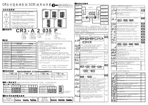
CR SCR 系列電熱調整器()使用說明書琦勝企業有限公司CONCH ELECTRONIC CO.,LTD-3 A 2035P控制輸出 選購功能 電壓規格 電流規格 控制方式1:2:3223:33單相相線 單相線相線D:A:V:W:標準型電流偵測電壓偵測功率偵測2:220V 4:440V (380V)035:35A : :450:450AP:Z:C:3相位零位相半波(空白):單相自行設定220, 380, 440V 15% 50/60HZ±200240VAC 90~240V AC/DC()~(附掛風扇機種)。
無風扇機種35A,50A,75A,100A,125A,150A,225A,300A,450A 相位控制或零位控制單相機種可自行設定()0~5V,1~5V(20K)0~10V,1~10V(100K)0~20mA,4~20mA(250)阻抗阻抗阻抗歐姆類比控制:阻抗對應。
控制0~5V(20K)0.0~100.0%on/off :Hi=3.4V,Lo=2.2VRS-485ModBus RTU ASCII 介面,支援協定或格式。
0.1% / 1%依規格採自然冷卻或附掛風扇AC2000V/1分鐘電源端、訊號端及散熱片間)(2KV 5KHZ20M /500V Ω以上電源端、訊號端及散熱片間)(ABS (UL94V)主電源電壓控制電源額定電流控制方式控制信號VcmdE ADJ .控制訊號串列通訊解析度線性度/冷卻方式環境溫度溼度/耐壓強度耐雜訊絕緣阻抗外殼材質-10~+50C/under 90%RH°0.0~100.0%輸出控制範圍請確定控制訊號的輸入類別再依據下表調整,以免發生控制異常。
位於主控板上的開關DIP S W 1lCRx-xxxxP /相位零位控制設定注意變更控制模式必須重新開機:外觀圖示DOC No.T10-00024/ V2.013425異常顯示按住鍵清除([SET]+[UP])Vcut=”0V ”,HLtd=90%,LLtd=10%的控制效果STUP=10s (的輸出延遲效果5)開機或待機超過分鐘RESP=2s 的輸出延遲效果Vcut=”LLtd ”,HLtd=100%,LLtd=10%的控制效果● 最小/最大輸出量與的關係Vcmd(Ccmd)● 緩啟動時間反應時間與輸出的關係(STUP),(RESP)註:為通訊控制訊號請參考通訊控制Ccmd ,[]本控制器可以利通訊方式操控的輸出量,以取代的作用。
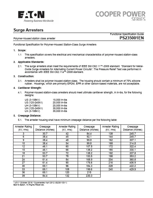
Surge ArrestersFunctional Specification GuidePolymer-housed station class arresterPS235001EN1 of 4 • October 2016 • Supersedes April 2012 (G235-103-1)Functional Specification for Polymer-Housed Station-Class Surge Arresters1. Scope:1.1This specification covers the electrical and mechanical characteristics of polymer-housed station-class arresters.2. Applicable Standards:2.1. The surge arresters shall meet the requirements of IEEE Std C62.11™-2005 standard “Standard for Metal -Oxide Surge Arresters for Alternating Current Power Circuits”. The Pressure Relief Test was performed in accordance with IEEE Std C62.11a™-2008 standard.3. Construction:3.1. Arresters shall be polymer-housed station-class. The housing should contain a minimum of 75% siliconerubber. Housings, which are primarily EPDM, EPR or other carbon-based materials, are not acceptable. 4. Cantilever Strength:4.1. Polymer-housed station-class arresters should meet ultimate cantilever strength, in in-lbs, for the followingdesigns:US (3-108kV) 15,000 in-lbs US (120-240kV) 20,000 in-lbs UH (3-108kV) 20,000 in-lbs UH (120-240kV) 35,000 in-lbs UX (3-108kV)35,000 in-lbs5. Creepage Distance:5.1. The arrester housing shall have minimum creepage distance per the following table:6. Terminals6.1. Terminals shall have solderless clamp-type connections suitable to accept up to 1.15” diameter conductors.7. Mounting Provisions:7.1. The arrester shall be supplied with a 3-hole mounting base using an 8.75”-10” diameter bolt circle pattern.The bolt-holes should be sized for .5” diameter bolts.8. Nameplate:8.1. The arrester should specify the manufacturer name, catalog number, serial number, arrester rating andMCOV. It should be permanently affixed to the mounting base.9. Protective Characteristics:9.1. The arrester shall have discharge voltages, which do not exceed the following single-impulse dischargeenergy ratings:US - Standard Energy Handling (minimum 3.9 kJ/kV of MCOV)UH – High Energy Handling (minimum 6.2 kJ/kV of MCOV)UX – Extra-High Energy Handling (minimum 10.0kJ/kV of MCOV)10. Standard Production Tests:10.1. Every metal oxide varistor and arrester shall be 100% production tested as follows to demonstratecompliance with the manufacturers’ specifications. Test report should be supplied with each arrester.Each arrester shall be marked with a unique serial number to allow tracking for at least 20 years fromdate of production.10.1.1. Metal Oxide Varistor Tests10.1.1.1. Measure Reference Voltage at specified Reference Current. This voltagelevel must fall within the parameters established by the manufacturer.10.1.1.2. The discharge voltage of each MOV must be measured per IEEE StdC62.11™-2005 standard, Section 13.2, “Discharge Voltage Test”.10.1.1.3. The leakage current must be measured by a method prescribed by themanufacturer.10.1.2. Complete Arrester Tests10.1.2.1. The partial discharge must be measured at no less than 1.05 times MCOV.10.1.2.2. The Watts Loss must be measured at no less than 1.05 times MCOV.10.1.2.3. The arrester reference voltage must be verified for each arrester.11. Quality Assurance11.1. Any varistor or complete arrester that does not comply with the requirements of these specifications shallbe rejected.。
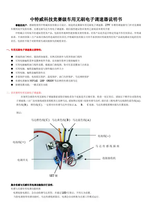
中特威科技竞赛级车用无刷电子调速器说明书尊敬的用户:感谢您使用中特威科技有限公司设计、制造的竞赛级车用无刷电子调速器。
ZTW 车模用调速器专门针对竞赛级车模用而开发的有感,无感无刷马达专用电子调速器。
我们强烈建议您在使用之前阅读本使用手册中特威公司有权不经通知变更其产品,包括其外观和性能参数及使用要求;对其产品是否适合特定用途不作任何保证、申明或承诺。
不承担因第三方产品相关修改所造成的任何责任,中特威科技有限公司亦不承担因应用或使用任何产品或电路而引起的任何责任,包括但不限于对附带损失或间接损失的赔偿责任。
一、车用无刷电子调速器主要特性:● 快速的油门响应、强劲的加速度、比例式的刹车与优异的油门线性 ● 可用电脑编程菜单设置和软件升级,还有操作简单方便的编程卡 ● 可用电脑编程油门线性设置,根据油门曲线图,您可任意设置油门点状态 ● 可用电脑,编程盒编程前进与倒车输出功率大小 ● 可用电脑,编程盒编程刹车比● 多重保护功能:电池低压保护、温度保护、油门失控保护、马达堵转保护 ● 有感电调兼容NOV AK LRP ORION 等品牌的有感无刷马达 ● 按键设置功能;一键式复位功能二、首次使用车用无刷电子调速器:在使用全新的车用无刷电子调速器前请您仔细检查各个连接是否正确可靠。
检查一切正常后,请按以下顺序启动您的电子调速器。
(出厂没有接线或您需要配其它品牌马达,请按图示连接)连接有感马达时,请注意三根电调马达线颜色蓝色线( A )、 黄色线( B )、 橙色线( C )、一定要对应有感马达外壳标示A 、 B 、 C 连接。
马达传感线要顺应插头位置连接。
图示:集合有感与无感车用电调功能指示灯说明: 有感与无感车用电调功能转换电调连接电源后,会自动检测马达类型,并通过LED 灯指示,不用人为设置。
当您电调使用有感功能时,马达传感线掉落后,电调会自动转换为无感工作模式运行。
SET 键马达橙色线( C ) 马达黄色线( B ) 马达蓝色线( A ) 电池线( + )电池线( – )电调开关连接接收机马达传感线插座LED灯亮与闪烁指示相应功能说明有感/无感集成电调指示灯说明功能状态功能状态LED灯功能状态LED灯指示电池低压红色LED 闪烁电调与马达过热(95℃)红色橙色LED 长亮配用有感马达红色橙色LED 长亮配用无感马达橙色LED 长亮有感电调指示灯说明功能状态功能状态LED灯功能状态LED灯指示电池低压红色LED 闪烁电调与马达过热(95℃)红色橙色LED 长亮配用有感马达红色橙色LED 长亮正向模式. 红色 LED 长亮双向模式橙色LED 长亮无感电调指示灯说明功能状态功能状态LED灯功能状态LED灯指示电池低压红色LED 闪烁电调过热(95℃) 红色橙色LED 长亮配用无感马达橙色LED 长亮正向模式. 红色 LED 长亮正向模式. 红色 LED 长亮1.油门行程设定:首先关闭电调开关,连接电池,再打开您的车用发射机电源,将油门通道方向设置为(REV),油门微调设置为(0),油门通道的EPA/ATV正反向均设置为最大按下SET键不松开,将电调开关打到ON位,等待4秒左右,电调橙色LED亮,这时把SET键松开,同时把您的发射机油门拉杆拉最大,红色LED闪烁3秒左右长亮,马达滴响后;再把油门拉杆推到最小,橙色LED闪烁3秒左右长亮,马达滴滴响后;把发射机油门拉杆置自然位,红色LED、橙色LED、同时闪烁3秒左右长亮,马达滴滴响后,2个LED熄灭;油门行程设定OK, 关闭电调开关2.打开电调开关,您的电调现在可以工作了三. 可编程的车用无刷电子调速器功能说明与出厂默认图示:功能值编程项目1 2 3 4 5 6 7 8 91.低电压关断值2.6V/节 2.8V/节3.0V/节 3.2V/节 3.4V/节不保护2.运行模式单向带刹车双向带刹车3.马达进角2度4度6度8度12度4.启动加速度低中高最高5. 反向工作输出功率比20% 30% 40% 50% 60% 70% 80% 90%100%6.正向工作输出功率比0% 20% 30% 40% 50% 60% 70% 80%90%7.刹车力比10% 20% 30% 40% 50% 60% 70% 80%100%8.拖刹力比4% 8% 12% 15% 20% 25% 30%9.电调工作频率8KHz 16KHz10.油门自然位宽度2% 3% 4% 5% 6%四.可编程的车用无刷电子调速器功能说明:我们的车用无刷电子调速器允许您针对自身需求来编程所有功能,充分体现了产品以用户为本的特点1. 低电压关断值●自动检测电池节数.出厂默认3.0V/节关断根据您使用的电池,通过电脑软件或编程盒设置您的电池类型与低压关断值;这样可使电调工作时随时监测电池电压,一旦电池电压低于设置低压点,电调将停止工作.●当使用镍氢.镍隔电池时,您不需要设置关断电压来保护电池。

Voltage selector switch, 6 stages, serie-parallel, panel mountingSee below:Approvals and CompliancesDescription- Voltage Selector , 6 stages - Series-parallel connections - Solder terminals ReferencesAlternative: version for PCB mounting SWZ2 (Print)T echnical DataRatings IEC: 6.3 A / 250 VAC; 50 HzUL: 10 A / 250 VAC; 60 HzCSA: 6.3 A / 250 VAC; 60 Hz Mounting Panel mount from front side Attachment Screw-on mountingTerminal SolderNumber of Stages 6Lifetime300 operating cycles (without load) Degree of Protection IP40Protection Class Suitable for appliances with protectionclass II acc. to IEC 61140 Allowable Operation Tempe-rature-40 °C to 85 °CClimatic Category25/85/21 acc. to IEC 60068-1 Material: Socket Thermoplastic, black, UL 94V-0 Weight12.4 g Solderability350 °C / 2 sec acc. to IEC 60068-2-20,Test Ta, method 2Resistance to Soldering Heat350 °C / 10 sec acc. to IEC 60068-2-20,Test Tb, method 2Insulation Resistance> 10'000MΩ (500VDC; 1min)Contact Resistance< 10 mΩ at 20 mVDielectric Strength> 2kVAC between L-N> 4kVAC between L/N-PE(1min; 50Hz)Clearance and Creepage Di-stance> 3mm> 8mm between L/N-PEResistance to Vibration acc. to IEC 60068-2-6, test FcPanel Thickness S max 4 mmApprovals and CompliancesDetailed information on product approvals, code requirements, usage instructions and detailed test conditions can be looked up in Details about ApprovalsSCHURTER products are designed for use in industrial environments. They have approvals from independent testing bodies according to national and international standards. Products with specific characteristics and requirements such as required in the automotive sector according to IATF 16949, medical technology according to ISO 13485 or in the aerospace industry can be offered exclusively with customer-specific, individual agree-ments by SCHURTER.ApprovalsThe approval mark is used by the testing authorities to certify compliance with the safety requirements placed on electronic products.Approval Reference T ype: SWZApproval Logo Certificates Certification Body DescriptionVDE Approvals VDE Certificate Number:UL Approvals UL UL File Number: E72661CSA Approvals CSA CSA Certification Record: LR459451Product standardsProduct standards that are referencedOrganization Design Standard DescriptionDesigned according to UL 508Industrial control equipmentDesigned according to CSA C22.2 no. 55Fuseholder general requirements Application standardsApplication standards where the product can be usedOrganization Design StandardDescriptionDesigned for applications acc.IEC/UL 60950IEC 60950-1 includes the basic requirements for the safety of informationtechnology equipment.CompliancesThe product complies with following Guide LinesIdentification Details Initiator DescriptionCE declaration of conformity SCHURTER AG The CE marking declares that the product complies with the applicablerequirements laid down in the harmonisation of Community legislation onits affixing in accordance with EU Regulation 765/2008.REACH SCHURTER AG On 1 June 2007, Regulation (EC) No 1907/2006 on the Registration,Evaluation, Authorization and Restriction of Chemicals 1 (abbreviated as"REACH") entered into force.Dimension [mm] 47 mmPanel mounting hole23Diagrams Reverse viewA) Power mainsB) External connectionAll Variants Packaging Unit 25 PcsThe specifications, descriptions and illustrations indicated in this document are based on currentinformation. All content is subject to modifications and amendments. Information furnished is believed 05.02.2019。
AP系列SCR电力调整器使用说明书V2.1一、特点:●适用范围广泛:各种电阻丝、红外灯管、硅碳棒、硅钼棒、石墨、变压器等。
●可输入信号:0-20mA、0-5V、4-20mA、1-5V、0-10mA(订货时说明)、0-10V(订货时说明)。
●控制方式多样化:可PID仪表/PLC自动控制,可手动控制,可自动、手动同时控制,不需要切换。
●全面的故障检测及报警:缺相检测、可控硅击穿检测、负载开路检测、超温检测等,继电器输出报警信号。
报警的同时,自动关断电流输出,保护设备安全。
●限流保护功能:可设定电流最大值,超过设定值报警。
●过流保护功能,快速熔断器进行过流保护。
●智能软启动/软停止功能,电流延迟时间可调。
●功率调节线性化:阻性负载时,输出功率与输入信号成正比。
●供电便捷:220VAC直接供电。
●两路直流稳压电源输出:5V、24V,方便外接变送器、传感器供电。
二、型号说明:2 主回路接线图:AP1XX主回路AP2XX主回路AP3XX主回路AP4XX主回路3 AP系列产品型号目录如下:表1:AP1XX系列产品目录:型号 控制方式 电流(A) 尺寸(L*W*H)重量(Kg)冷却 安装孔位图AP130相位/零位30157*108*154 1.5 自冷F1AP140 40 AP150 50AP175 75 182*108*154 1.8风冷 F3AP1100 100AP1125 125251*108*154 2.5 F4AP1150 150AP1175 175285*140*1874F5AP1200 200AP1250 250AP1320 320AP1500 500AP1800 800 285*271*201 10 F7 表2:AP2XX系列产品目录:型号 控制方式 电流(A) 尺寸(L*W*H)mm重量(Kg)冷却 安装孔位图AP230零位型30182*108*154 1.8风冷F3AP240 40AP250 50AP275 75 251*108*154 2.5 F4 AP2100 100AP2125 125285*140*187 3.8F5AP2150 150AP2175 175AP2200 200 325*140*187 4.7 F6AP2250 250285*271*20110F7AP2320 320AP2500 500表3:AP3XX系列产品目录:型号 控制方式 电流(A)尺寸(L*W*H)mm重量(Kg)冷却 安装孔位图AP33030182*108*154 1.8风冷F3AP340 40AP350 50 251*108*154 2.5 F4AP375相位/零位75AP3100 100 285*140*187 3.8 F5AP3125 125325*140*1874.7F6AP3150 150 AP3175 175AP3200 200285*271*20110F7AP3250 250AP3320 320表4:AP4XX系列产品目录:型号 控制方式 电流(A) 尺寸(L*W*H)mm重量(Kg)冷却方式 安装孔位图AP430相位/零位30182*108*154 1.8风冷F3AP440 40AP450 50 251*108*1542.5 F4AP475 75AP4100 100 285*140*187 3.8 F5AP4125 125325*140*1874.7F6AP4150 150 AP4175 175AP4200 200285*271*20110F7AP4250 250AP4320 3204 使用环境注意事项:A 使用环境温度: -10~45℃B 使用环境湿度: ≤90%RHC 保证安装柜的良好通风5 产品选型注意事项:A AP2XX系列只适用于除红外灯管外的纯阻性负载;AP1XX,AP3XX,AP4XX适用于阻性负载、感性负载(需加阻容)。
• Phase angle or burst firing control mode • Current loop control, 4 – 20 mA, 20 – 4 mA, 0 – 20 mA and 20 – 0 mA• Voltage control, 0 – 10 V d.c. and 10 – 0 V d.c.• Potentiometer control, 0 –10 kΩ and 10 – 0 kΩ• Rated operational voltage, 230 and 480 V • Control voltage, 19 – 28 V a.c./d.c.• DIN-rail mountable• Built-in varistor protection • LED status identification • IP 20 protection• Compact modular design • Easy and quick installation• Specification acc. to industrial standard • CE, EAC, cULus and LLC CDC TYSK208 – 2403019 – 2845ACI 30-1037N0057380 – 4803045ACI 30-1037N0059208 – 2405090ACI 50-1037N0058380 – 4805090ACI 50-1037N0060The versatile ACI analogue power controller is designed for very precise temperature and transformer control. Due to the built-inmicroprocessor the controller can operate in phase angle as well as in burst firing control mode.The controller automatically adapts to the load to ensure a smooth inrush, and in burst firing mode it will further eliminate theDescriptionunwanted effects of DC magnetizing ontransformers. The ACI unit is easily connected to a PLC/regulator by means of one of the selectable input signals.The analogue controller ACI is typically used as controller for heaters and infrared lamps but also ideal on transformer controlled processes.Selection guideOperational voltage V a.c.Operational current A Supply voltage V a.c. / d.c.Dimensionsmm Type Code no.FeaturesContents PageFeatures (3)Description (3) (3)SelectionTechnical data (4)Operating at high temperature (4)Control selection (5)Function mode selection (5)Wiring (5)Applications (heater load) (6)Application (transformer load) (6)Overhead protection (7)EMC specification (7)Dimensions (8)Mounting instruction (8)40 °C 30A 50A 50 °C 25 A 40 A 60 °C 20 A 30 AOperational current max. AC-51 (heater load)30 A 50 A Operational current max. AC-56a (transformer load 30 A 30 A Operational voltage 50/60 Hz 230 V / 480 V Leakage current max. 1 mA Operational current min.10 mAControl methodPhase angle control Selectable linear power or linear voltage Burst firing controlSelectable cycle time : 0.4 – 60 secondsSemiconductor protection fusingType 1 co-ordination50 A gL/gG Type 2 co-ordination I2t(t=10 ms)1800 A2sControl circuit specificationsControl supply voltage19 – 28 V a.c./d.c.Control signalsCurrent loop control (voltage drop < 3 V) 4 – 20 mA, 20 – 4 mA, 0 – 20 mA and 20 – 0 mA Voltage control (input resistance > 300 kW)0-10 V d.c. and 10-0 V d.c.Potentiometer control0-10 kΩ and 10-0kΩIsolationControl inputFloating control input Voltage line to control 2.5 kV a.c.Voltage supply to control 500 V a.c.Protection Supply and control inputs are protected against overload and over voltageEMC immunityMeets requirements of EN 50082-1 and EN 50082-2InsulationRated insulation voltage, Ui660 V Rated impulse withstand voltage, Uimp 4 kV Installation categoryIIIThermal specificationPower dissipation, continuous duty 1.2 W/APower dissipation, intermittent duty 1.2 W/A x duty cycle Ambient temperature range -5 – +40°CCooling method Natural convectionMountingVertical (see general mounting instructions)Max. ambient temperature with limited current 60°C, see derating for high temperatures in chart below Storage temperature range-20 – +80°C Protection degree/ pollution degreeIP20/ 3MaterialHousing Self exstinguishing PPO UL 94V1Heatsink Aluminium black anodised BaseElectroplated steelTechnical dataOutput specificationsOperating at high temperatureAmbient temperatureACI 30 ACI 50Control mode selectionSelection of control signalThe type of control signal, current, voltage or potentiometer can be selected on the rotary switch.ProtectionThe control input is protected against overload. If the current exceeds 25 mA, the loop willswitch OFF and the LEDs will indicate failure. The input will not be damaged if the 24 V supply by mistake is connected to the signal input. Control input terminals are marked with + and -. Correct polarity must be observed. The control input is floating.Insulation voltageLine voltage to control: 2500 V a.c.Supply to control: 500 V a.c.Function mode selectionPhase anglePhase angle control is used for control of infrared lamps or heaters in IR heating applications. Two different operation modes can be selected Linear voltage: The load voltage varies linearly with the control signal.Linear power: The power delivered to the load varies linearly with the control signal.Burst firingIn burst firing mode full sine waves are supplied to the load. Consequently DC magnetizing of the supply transformer is avoided. The number of sine waves varies linearly with the control signal. Adjustable cycle times from 400 ms to 60 sec.WiringApplications(heater load)Single-phase 230 V a.c. (400 V a.c.)Phase angle and burst firing modeThree-phase with neutralPhase angle and burst firing modeThree phase with single-phasecontactor ECI-1 as slave400VACI 30-1 6.9 kW 12 kWACI 50-1 11.5 kW 20 kW3 x ACI 30-1 20.7 kW3 x ACI 50-1 34.5 kWACI 30-1 20.7 kWACI 50-1 34.5 kWTransformer loadsACI load driving capability includes transformerapplications which means that low voltage loadscan be controlled via an isolation transformerwithout any surge or DC magnetising of thetransformer.Switching transformersThe problem in transformer switching is themagnetic circuit. When the transformer isswitched off, (H = 0) the field (B) remains on ahigh level due to the high remanence of moderntransformer core material. At initial turn-on wherethe remanence is unknown the ACI will soft startto avoid the high current surge and at repetitiveturn-on the switch-off polarity is “remembered”so next turn-on will be in the opposite polraty,thereby eliminating the high current surgenormally seen in transformer applications. DCmagnetising is eliminated by operating in fullcycle mode only.Phase angle modeAn initial turn on ACI will soft start thetransformer to the voltage level set by theanalogue input.Application(transformer loads)Burst firing modeAn initial turn on ACI will soft start thetransformer to full on mode. The controller willonly allow full cycles to be supplied to thetransformer hereby eliminating current surgesand DC saturation of the transformerApplications(transformer loads)Overhead protection If required the power controller can be protectedagainst overheating by inserting a thermostat inthe slot on the right-hand side of the controller.Order: UP 62 thermostat 037N0050The thermostat is connected in series with thecontrol circuit of the main contactor. When thetemperature of the heat sink exceeds 100°C themain contactor will be switched OFF. A manualreset is necessary to restart this circuit.EMC specification The power controller ACI is in conformity with thestandard IEC/EN 60947-4-3 ACSemiconductor Controllers and Contactors fornon motor loads.Burst firing control mode:No action necessaryPhase angle control mode:I <10 A, no action necessaryI >10 A, connect 1uF capacitor from N/L to L1 asshown above.Dimensions Mounting instructionThe controller is designed for vertical mounting. If the controller is mounted horizontally, the load current must be reduced by 50%.The controller needs no side clearance.Clearance between two vertical mounted controlls must be minimum 80 mm (3.15”).Clearance between controller and top and bottom walls must be minimum 30 mm (1.2”).。
第一章SCR电力控制器总述前言SCR电力控制器(SCR POWER CONTROLLER),目前在工业中已被广泛应用于各种电力设备中,诸如窑炉、热处理炉、电气高温炉、高周波机械、电镀设备、印染设备、涂装设备、射出机、押出机等等,然而因为负载的不同,使用环境的限制,而又有各种不同的控制模式及各种追加配备,如相位控制(Phase Angle Control),分配式零位控制(Distributed Zero Crossover),时间比例零位控制(Time Proportional Zero Crossover)。
基于此,本公司研制了P/E系列各种不同控制模式之电力控制器,以满足各用户的需要。
P/E系列SCR电力控制器,完全采用SCR POWER MODULE密封的IC化电路板,使整个控制器简单轻便,以提高控制器的可靠度,当要使用本控制器时,请详读本说明,以了解各种控制器的结构、功能、接线方法。
SCR电力控制器有多种不同的叫法:如晶闸管电力控制器,可控硅电力调节器,可控硅电力调功器,功率控制器等,虽然叫法不同,但所指的都是同一种产品。
本公司以SCR电力控制器来命名。
1,原理简介SCR电力控制器的基本原理是通过控制信号输入,去控制串在主回路中的SCR(晶闸管)模块,改变主回路中电压的导通与关断,由此达到调节电压或功率的目的。
控制器一般是由控制板加上主机(主回路)组成。
SCR电力控制器又可分为调压器和调功器。
采用相位控制模式的SCR电力控制器可叫做调压器,它可以方便地调节电压有效值,可用于电炉温度控制,灯光调节,异步电动机降压软启动和调压调速等,也可用做调节变压器一次侧电压,代替效率低下的调压变压器。
采用零位控制模式的SCR电力调节器可叫做调功器,也叫周波控制器。
它对交流电压的周波进行控制,通过控制负载电压的周波通断比来控制负载的功率,多用于大惯性的加热器负载。
采用这种控制,即实现了温度控制,又消除了相位控制时带来的高次谐波污染电网,不过控制精度有所降低。
Z P C CT V UV ZP FUSE FUSE
R
T
U
W
FUSE R
S
U
V
FUSE FUSE R
S
T
U
V
W
FUSE LOAD S
V
輸出(零位.相位)可變更全控機型輸出(零位.相位)可變更
FUSE FUSE
R
S
T
U
V
W
FUSE LOAD
LOAD LOAD 相位半控機型輸出零位控制二相T6-2-4-XXX-Z
T6-1-4-XXX
T6-3-4-XXX-Z T6-4-4-XXX
T6-5-4-XXX-P
不可接零線否則會失控
可接零線不可接零線否則會失控FUSE R
U
零位.相位)可變更LOAD 必須接取樣電源
零位輸出:只適用一般純電阻絲負載
機型適用負載種類及特性
AT
ower
通訊界面,最多可連接32台SCR,最長距離1200M
PC FUSE FUSE
R
S
T
U
V
W
FUSE L OAD
~220V ~220V R UN C OM E 3E 2E 1
I N+I N -485+485-A LM A L O A L C
M
板工作電壓IMMI PLC
外部電位器溫控器T IC
外部電位器
溫控器
T IC
+-
溫控器
T IC
溫控器
T IC
+-
手動外部電位器
溫控器
T IC
+-
外部電位器
手動/自動.切換控制
Modbus 485
PLC
NC NC
X
X
X
4~20mA 0~10V
PC
FUSE FUSE R
S
T
U
V
W
FUSE LOAD T6-4-4-XXX FUSE FUSE R
S
T
U
V
W
FUSE LOAD T6-4-4-XXX FUSE FUSE
R
S
T
U
V
W
FUSE LOAD T6-4-4-XXX
FUSE FUSE R
S
T
U
V
W
FUSE LOAD T6-4-4-XXX FUSE FUSE R
S
T
U
V
W
FUSE LOAD T6-4-4-XXX PC
IMMI
PLC
FUSE FUSE
R
S
T
U
V
W
FUSE T6-3-4-XXX-ZP
220V 220V UN OM N+-85+85-LM O C
+10V RUN STOP ERR
FUSE R
S
U
V
FUSE R
S
U
V
FUSE T6-1-4-XXX
T6-4-4-XXX
220V 220V UN OM N+85+-LM O C
+10V 220V 220V UN OM 321
N+-85+85-LM O C
+10V 燈泡亮度明暗平滑變化(相位輸出機型);燈泡閃爍變化(零位輸出機型)負載燈泡必須60W 注意式及T
W
FUSE
RUN STOP ERR
異常時亮燈停止時亮燈STOP 指示燈ERR 指示燈運轉時亮燈RUN 指示燈智慧
7
處理方式,及改善方法
1:檢查R 相負載發熱絲是否燒毀造成電流異常 使用三用電表,測量負載是否正常1:檢查S 相負載發熱絲是否燒毀造成電流異常 使用三用電表,測量負載是否正常1:檢查T 相負載發熱絲是否燒毀造成電流異常 8
修方式檢測維異常顯示值
異常原因
ERROR R-OL
R 相負載電流異常 電流誤差超過AL P 設定值ERROR S-OL
ERROR T-OL
S 相負載電流異常 電流誤差超過AL P 設定值T 相負載電流異常 才有此功能 才有此功能 AT電流機型 AT電流機型
AT電流機型
FUSE FUSE
R
S
T
U
V
W
FUSE TAISEE
T6-SCR
CPU
RUN ERR
STOP
SET
RUN
STOP
Esc
T6
TAISEE ELECTRONIC CO.,LTD
HT
45~65HZ 電源頻率同步追蹤
T G 觸發
M
8
RS-485
POWER
LOAD
485+485-A LM A L C A L O 220V 220V
N+
N-
OM UN 3
21
顯示設定界面
Rs485通訊接口
異常警報輸出工作電壓
10V 散熱風扇
Fan
Temp CT3J2R
S T
電(流.壓偵測)
散熱器溫度
10V
9
910
步驟6: 對指令訊息下一個字節重覆步驟2至步驟5;直到所有字節全部處理完成
C R C 暫存器的內容即是C R C 值,傳遞指令時必須將C R C 的高低字節交換順序,
即是低字節先被傳送
計算CRC 值範例:(用C 語言編寫的C R C 計算範例)
即函數需要兩個參數:
Unsigned char* data;指向消息緩衝區之指針Unsigned char lenght;消息緩衝區中的字節數目函數將返回Unsigned integer;類型的CRC 值
Unsigned integer CRC_check(unsigned char* data,unsigned char lenght)
{
Int x;
Unsigned int reg_crc=0XFFFF While(lenght--)
{
reg_crc^=*data++;fox(x=0;<8;x++){
If(reg_crc&0x01) //LSB(b0)==1
{reg_crc=(reg_crc>>1)^0xa001;}else
{reg_crc=reg_crc>>1; } }
}
}
return reg_crc;
CRC 偵錯碼:
R T U 模式採用C R C (C y c l i c a l R e d u n d a n c y C h e c k )偵測錯誤,C R C 偵錯由以下幾個步驟計算:步驟1: 載入一個內容為F F F F H 之16位暫存器(稱為C R C 寄暫存器)
步驟2: 將指令訊息第一個字節與16-B I T C R C 寄暫存器的低次字進行 E x c l u s i v e O R
運算,並將結果存回C R C 暫存器 步驟3: 將C R C 暫存器之內容向右移1b i t ,最左位填入0,檢查C R C 暫存器最低位值步驟4: 若C R C 暫存器最低位值為0,則重覆步驟3;否則將C R C 暫存器與A 001H 進行
E x c l u s i v e O r 運算 步驟5: 重覆步驟3及步驟4;直到C R C 暫存器之內容已左移了8-b i t ,該字節已經完成處理P C 通訊程式範例:(下列是簡易通訊程式,P C 與S C R 通訊用C 語言編寫範例)
M o d b u s R T U 之通訊程式
#include<stdio.h>#include<dos.h>#include<conio h>.#include<process.h>#define THR 0X0000#define RDR 0X0000#define BRDL 0X0000 #define LCR 0X0003 #define MSR 0X0006
#define IER 0X0001 #define BRDH 0X0001 {int i;
(PORT+MCR,0x08);/*interrupt enable */(PORT+IER,0x01);/*interrupt as data in */(PORT+LCR,(inportb(PORT+LCR)l0x80));
/*the Baudrata can be access as LCR.B7==1 */
utportb(PORT+BRDL,12);/*set baudrate =9600, 12=115200/9600*/utportb(PORT+BRDH,0x00);utportb(PORT+LCR,0x07);/*<8,N,2>=0x07,<8,E,1>=0x1B,<8,0,1>=0x0B*/for(i=0;i<8;i++){
000While(!(inportb(PORT+LSR)&0x20));/*wait until THR empty*/utportb(PORT+THR,send_data[i]); /*send data to THR*/0}i=0
While(!kbhit())
{
If(inportb(PORT+LSR)&0x01) /*b0==1,read data ready*/{
read_data[i++]=inportb(PORT+RDR) ;read data form RDR*/}},x0;/*t */t
#define MCR 0X0004 #define LSR 0X0005 }
utportb utportb utportb 000t Unsigned read_data[100];
Unsigned read_data[10]={0x01,0x03,0x00,0x0B,0x00,0x01,0xF5,0xC8};11
12
13。