FP系列变送器说明书
- 格式:pdf
- 大小:536.70 KB
- 文档页数:28
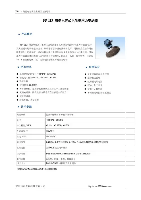
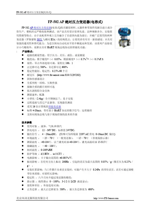
FP-502 AP绝对压力变送器(电容式)FP-502 AP绝对压力变送器(电容式)的关键原材料、元器件和零部件均源自进口或合资生产,整机经过严格组装和测试。
该产品具有设计原理先进、品种规格齐全、安装使用简便等特点。
由于该机型外观上完全融合了目前国内最为流行,并被广泛使用的两种变送器(罗斯蒙特3051与横河EJA)的结构优点,让使用者有耳目一新的感觉,并具有很强的通用性和替代能力。
为适合国内自动化水平的不断提高和发展,该系列产品除设计小巧精致外,更推出具有HART现场总线协议的智能化功能。
; 产品特点:●超级的测量性能,用于压力、差压、液位、流量测量●精度高:数字精度+(-)0.05%;模拟精度+(-)0.5%~+(-)0.1%F.S●量程、零点外部连续可调,量程比100:1●正迁移可达500%、负迁移可达600%●稳定性能好,稳定性:0.25% 60个月●耐过压( 010-********)●固体传感器设计●全系列统一结构、互换性强●接触介质的膜片材料可选●低压浇铸铝合金壳体●测量速率:0.2S●小型化(2.4kg)全不锈钢法兰,易于安装●过程连接与其它产品兼容,实现最佳测量●采用16位计算机的智能变送器●标准4-20mA,带有基于HART协议的数字信号,远程操控●支持向现场总线与基于现场控制的技术的升级技术参数●使用对象:液体、气体;和蒸汽●供电电压:12~36V DC,标准值24VDC;●输出信号:4~20mADC;(特殊可为四线制220V AC供电0-10mA DC 输出)●环境温度:-25~70℃(一般变送器),-15~70℃(带现场指示器)●测量温度:-40-104℃,法兰灌充硅油-40-104℃,灌充高温硅油15-315℃●储藏温度:-40~100℃;●相对温度:0-100%RH●防护等级:dⅡBT4 ,iaⅡCT5 ;●电源影响:小于输出范围的±0.005%/V;●振动影响:在任何方向上振动200Hz ,引起的误差为最大范围的0.05%/g(微差压为0.25%/g);●安装位置影响:当工作膜片未垂直安装时,可能产生不大于0.24Pa 的零位误差,误差可通过调整零位来消除,对量程无影响;●稳定性:六个月内不超过变送器的精度;●指示器:线性指示0~100%;3-1/2位LCD 液晶显示;●量程和零位:外部连续可调;●正负迁移:最大正迁移量为500% ,最大负迁移量为600%材料隔离膜片:316L不锈钢,哈式合金-C ,蒙耐尔合金,钽排气/排液阀:316L不锈钢,哈式合金-C,蒙耐尔合金法兰和接头:316L不锈钢,哈式合金-C ,蒙耐尔合金"O" 型圈:氟橡胶灌充液:硅油惰性油螺栓:316L 不锈钢电子壳体:低铜铝合金产品选型( 010-********)外形尺寸图。

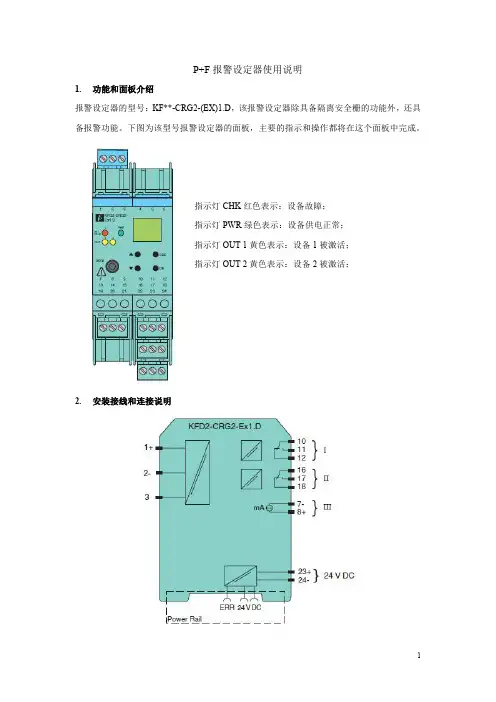
P+F报警设定器使用说明1.功能和面板介绍报警设定器的型号:KF**-CRG2-(EX)1.D,该报警设定器除具备隔离安全栅的功能外,还具备报警功能。
下图为该型号报警设定器的面板,主要的指示和操作都将在这个面板中完成。
指示灯CHK红色表示:设备故障;指示灯PWR绿色表示:设备供电正常;指示灯OUT1黄色表示:设备1被激活;指示灯OUT2黄色表示:设备2被激活;2.安装接线和连接说明上图为该报警设定器的侧面图形,在安装过程中,现场过来的4-20mA信号接在左侧“1-3”端子上,如果现场为配电信号则接在1,3端子上(1+、3-),如果现场为不配电信号则接在2,3端子上(3+、2-)。
图形的右侧有四个区域,其中23,24端子(23+、24-)给报警器提供24V电源;III区的7,8端子(8+、7-)去DCS系统柜相应的端子板上;I、II区则是输出去ESD的两个DI信号。
信号线分别接在10,11(11+、10-)以及16,17端子(17+、16-)。
I、II区对应于OUT1和OUT2指示灯。
因为一个变送器对应的信号可能存在高报(低报)或者高高报(低低报)两个报警限,所以有两个区,也对应有两个设备被激活的情况。
3.参数设置在报警设定器参数设置过程中,面板上有四个重要的按钮:“UP、DOWN、ESC、OK”。
同时摁住“OK”与“ESC”长达一秒,将进入参数设置的主菜单。
主菜单内有:输入(INPUT),输出(OUTPUT),单位(UNIT),服务(SERVICE)四个可操作项,这里只需要设置输入、输出以及单位即可。
通过“UP”或“DOWN”按钮,选择“UNIT”选项,点击“OK”,则进入单位设置,选择“4-20mA”,点击“OK”,完成单位的设置。
“INPUT”中存在一个线性检测“Line monitor”,点击“OK”,进行设置。
通过改变“LB”、“SC”可以对短路和断路进行检测。
如果LB选为ON,当输入信号小于0.2mA时,表示断路;如果SC选为ON,当输入信号大于22mA时,表示短路。
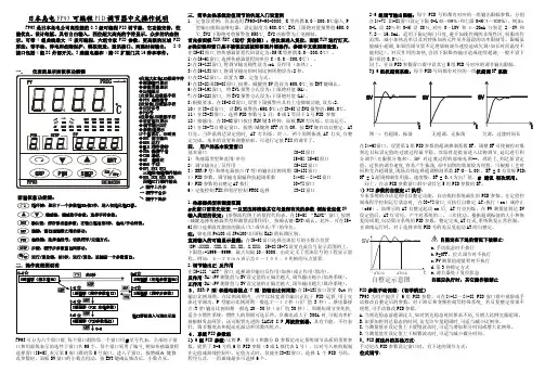
日本岛电FP93可编程PID调节器中文操作说明FP93是日本岛电公司高性能的0.3级可编程PID调节器,它功能完善,性能优良、设计细腻。
具有自由输入,四位超大高亮的字符显示,众多的状态指示。
可带4组曲线最大40段可编程,六组专家PID参数,更高级的区域PID 算法。
带手动、停电和故障保护、模拟变送、通讯接口、两路时标输出,I/O 接口包括4组DI外部开关、3路继电器和4路OC扩展门共16种和事件。
FP93可分为六个窗口群,每个窗口群的第一个窗口用.星号代表,全部的子窗口和用虚线表示的选件子窗口共95个。
每个窗口采用了编号,例如传感器量程选择窗口[5-5],表示第5窗口群的第5号窗口。
进入子窗口,按增减ù 键修改参数时,面板SV窗口的小数点闪动,按ENT键确认修改后,小数点灭。
三.简单加热系统定值调节的快速入门设置例1.定值设置例:仪表选用FP93-8P-90-0000, K型热偶0.0~800.0℃输入,P型输出接固态继电器。
设定温度为600.0℃,EV1上限绝对值报警值650.0℃,EV2下限绝对值报警值550℃, EV2的报警为上电抑制。
首先按面板RUN/RST(运行/复位键),使仪表进入复位,面板RUN运行灯灭,.确定键和窗口是不被锁定或被转移到外部操作,参照中文流程图设置:在[5-5]窗口,将传感器量程代码设定为:05(K型热偶0.0~800.0℃) 。
1)在[5-6]窗口,选择传感器量程的单位C(0.0~800.0℃)。
2)在[5-12]窗口,将调节输出极性设为:rA 反作用(加热)。
3)在[5-13]窗口,将调节输出的时间比例周期设为:2秒。
4)在[3-1]窗口,设置为ON,定值方式。
5)在[3-2]或[0-0]窗口,按增、减键将SV值设为600.0℃,按ENT键确认。
6)在[5-19]窗口, 将EV1报警方式设为:上限绝对值(HA)。
7)在[5-22]窗口, 将EV2报警方式设为:下限绝对值(LA)。
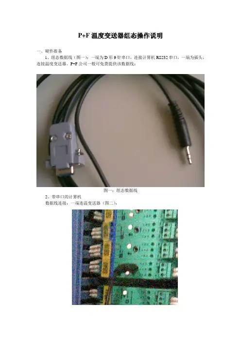
P+F温度变送器组态操作说明一、硬件准备1、组态数据线(图一):一端为D形9针串口,连接计算机RS232串口,一端为插头,连接温度变送器。
P+F公司一般可免费提供该数据线;图一:组态数据线2、带串口的计算机数据线连接:一端连温变送器(图二):图二:连接温变一端连计算机(图三):图三:连接计算机二、软件安装目前,P+F温度变送器组态软件版本为PACTware 3.5。
该软件一般需向P+F公司购买。
当对温变进行组态时,必须安装1、2、3、4、7共五个选项(图四):图四:软件安装必选项按安装向导完成软件安装。
三、组态步骤1、PACTware 3.5安装完成会在桌面有快捷方式(图五):图五:软件快捷图标2、双击软件快捷方式图标,打开组态软件(图六):图六:组态软件3、在“HOST PC”上右击鼠标,点击“Add device”:4、选中Device for中“P2P RS232 FDT”,点击“OK”,或直接双击“P2P RS232 FDT”:5、如下图右击鼠标,点击快捷菜单“Add device”:6、在“Device for”中选择温度变送器模块“KF*-UT2-*FDT”,并点击“OK”,或直接双击:7、注意红圈的地方,此时是没有连接通讯时的画面,如果没有以下参数画面,则双击左边红圈内“KF*-UT2-*FDT”:8、点击通讯连接图标:9、如果通讯连接正常,则“KF*-UT2-*FD Parameter”变为“KF*-UT2-*FD# Parameter”,即中间多了一个“#”符号,否则连接不正常;10、点击图标“Load from device”上载设备中信息,同时画面下部为出现上载信息进度条:11、上载完毕后,注意红圈处已从没通讯时的双通道设备变为与实际型号一致的单通道设备:12、我们所要进行的设置主要是“input”和“output”项。
对“input”进行设置:单击“input”前面的“+”号后会展开所属的选项列表。
F SeriesHUMIDITYAND HUMIDITY-TEMPERATURE TRANSMITTERS INSTRUCTION MANUALCONTENTS DESCRIPTION (3)OPERATION (4)Power Supply (4)Output Range (4)Temperature Operating Range and Temperature Limits (4)Humidity Limits (4)Temperature Compensation (4)Sensor Protection (5)Output Signals (5)Wiring Diagrams (6)Grounding (7)INSTALLATION (8)General Recommendations (8)Installation of the Base Plate (9)Installation of the Electronics Module (10)MAINTENANCE (11)Cleaning or Replacing the Dust Filter (through wall model) (11)Periodic Calibration Check (11)SPECIFICATIONS (13)PLEASE, READ THIS FIRST• Check the product for any physical damage that may have occurred during shipment. We carefully pack and routinely insure all shipments. If any damage has occurred, it is your responsibility to filea claim with the carrier, prior to returning the damaged product. Please note that our warranty doesnot cover damage during shipment.• See the label on the shipping box for information about the model number of the transmitter, the supply voltage as well as the type and range of the output signals. An identical label is also located under the printed circuit board.• Prior to installation, get fully familiarized with the operating limits of the product and with the installation instructions provided in this manual.• Do not unnecessarily remove the sensor protection (dust filter or slotted cap) from the probe. Both sensors (humidity and temperature) can be mechanically damaged by careless removal of the protection. The ROTRONIC HYGROMER humidity sensor looks like a small white paper tag. Do not remove from the probe!Each ROTRONIC instrument is carefully calibrated before shipment. No further adjustments should be required before installation. If you have any question or problem, please call our service department at 631/427-3898 and press 5 (or ask for extension 21).Transmitters of the F series are used to measure humidity or a combination of humidity and temperature in commercial HVAC installations, clean rooms, research laboratories and light (clean) manufacturing areas. The electronic circuitry is either of the 2-wire loop powered type or of the 3-wire type. Linearized output signals (DC current or voltage) are provided for transmission over a length of cable to a remote display, recorder, controller or data processing unit.The F series features the ROTRONIC HYGROMER capacitive humidity sensor. This well proven sensor offers exceptional durability and stability in all kinds of environments. This fact is reflected in the 3-year full warranty that covers the transmitters of the F series. Reliability is further enhanced by the easy-to-perform field calibration. Measurement accuracy and fast response are provided over the entire range of humidity conditions, even when the sensor is exposed to extremely high or low humidity over long periods of time. An electronic compensation circuit maintains the accuracy of humidity measurement at all temperatures.Models that measure both humidity and temperature, use an RTD Pt100 as the temperature sensor.F series transmitters include a base plate and a module (sensor and electronics) which plugs into the base plate. The base plate can be installed and wired without the module at the same time as general electrical work is being done. During that period of time, the electronics module can safely be stored away.The F series is available in the following configurations:Model Measurement Circuit Type InstallationF2C-W Humidity 2-Wire Loop Powered Space Mount (Surface)FT2C-W Hum. + Temperature 2-Wire Loop Powered Space Mount (Surface)F2C-D Humidity 2-Wire Loop Powered Duct Mount (Through Wall) FT2C-D Hum. + Temperature 2-Wire Loop Powered Duct Mount (Through Wall)F3V-W Humidity 3-Wire Space Mount (Surface)FT3V-W Hum. + Temperature 3-Wire Space Mount (Surface)F3V-D Humidity 3-Wire Duct Mount (Through Wall) FT3V-D Hum. + Temperature 3-Wire Duct Mount (Through Wall)Power SupplyTransmitters of the F series require the following supply voltage:• 2-Wire loop powered transmitters: 10..35 VDC - depending on the load connected to the output(s) The minimum supply voltage can be determined as follows: V min = 10 V + [0.02 x Load (ohm)]. For the maximum load of 500Ω, the minimum supply voltage is 10 + [0.02 x 500] = 20 VDC. The maximum current consumption is 20 mA per output circuit.• 3-Wire transmitters: 10..35 VDC or 24 VACModels with a current output require a minimum of 15 VDC when the load connected to the output(s) is 500Ω. 3-Wire transmitters have a typical current consumption of 16 mA (Humidity only) or 32 mA (combined humidity and temperature).Output RangeThe range of the relative humidity output is 0 to 100%RH. The temperature output depends on the range specified when ordering (see label on shipping box and under the printed circuit board). Temperature Operating Range and Temperature LimitsThe F series can operate within 23 to 122°F (-5 to 50°C) at the electronics.The temperature operating range of space mount models (surface) is the same as the temperature limits of the electronics. For through wall (duct) installation models, the temperature limits at the sensor(s) are -22..158°F (-30..70°C).Operating the transmitter and/or its probe outside of the temperature limits can result in permanent damage.Humidity LimitsAs far as possible, avoid sudden condensation at the sensors. When measuring at high humidity, condensation may occur on the humidity sensor due to a sudden difference in temperature with the environment. This does not damage the sensor. However, this will produce an overflow reading (an output signal of more than 100 %RH) for as long as condensation is present on the humidity sensor. Temperature CompensationPractically every make of relative humidity sensor requires a compensation for the effect of temperature on the humidity output signal in order to measure accurately over a wide range of temperature conditions. In the specific case of an instrument using a capacitive sensor, compensation is required because the dielectric characteristics of both the water molecule and the hygroscopic polymer used in the sensor vary with temperature.The electronic circuit of the F series uses an NTC located next to the humidity sensor to provide automatic compensation for the effect of temperature on the humidity sensor. The temperature compensation uses normal room temperature as a reference. Because of this, calibration of the unit is done at normal room temperature rather than at the temperature of operation at the sensor.Sensor ProtectionTransmitters of the F series for through wall (duct) installation are supplied as a standard with a dust filter to protect the sensors. Space mount transmitters do not have a dust filter since the sensor(s) relies on natural ventilation through the slots of the enclosure.When using a transmitter for through wall installation in a clean environment with rapidly changing conditions, it is recommended to use a slotted cap with screen (available from ROTRONIC) as opposed to using a dust filter.Never use the transmitter without protecting the sensors with either a filter or a slotted cap.Output SignalsThe F series is available with the following output signals:• 2-Wire loop powered transmitters: 4-20 mAThe transmitter behaves as a variable load and adjusts the current flowing through the terminals as a function of relative humidity and temperature. The output signal may be read with any current sensing device having a maximum impedance of 500 ohms. When several devices are connected in series with the transmitter, the resulting impedance should not exceed 500 ohms, wiring included.• 3-Wire transmitters: 0-20 mA, 4-20 mA, 0-1 V or 0-5 V. The output signal depends on the type specified when ordering (see label on shipping box and under the printed circuit board).The output signals are linear and are consistent with the requirements of most data/signal processing instrumentation (panel meter, controller, computer card, etc.).Units with current outputs behave as a variable source of current and adjust the current flowing through the terminals as a function of relative humidity and temperature. The output signal may be read with any current sensing device having a maximum impedance of 500 ohms. When several devices are connected in series with the transmitter, the resulting impedance should not exceed 500 ohms, wiring included.Units with voltage outputs behave as a variable voltage source and adjust the voltage across the terminals as a function of relative humidity and temperature. The output signals may be read with any voltage sensing device having a minimum impedance of 1000 ohms. When several devices are connected in parallel with the transmitter, the resulting impedance should not be less than 1000 ohms.Wiring DiagramsThe wiring diagram for transmitters that measure humidity only is as follows:3-Wire Transmitter with voltage output2-Wire Transmitter (4-20 mA output)Terminal number on base plateTerminal number on base plate3-Wire Transmitter with current output12Terminal number on base platenot used not usedThe wiring diagram for transmitters that combine humidity and temperature measurement is as follows:GroundingOperation of the F series does not require that the unit be electrically grounded. However, we recommend grounding the instrument, especially if the electronic circuits are subjected to a low humidity environment (less than 35 %RH).3-Wire Transmitter with voltage outputs2-Wire Transmitter (4-20 mA outputs) using two independent power suppliesTerminal number on base plateTerminal number on base plateTerminal number on base plate3-Wire Transmitter with current outputs2-Wire Transmitter (4-20 mA outputs)using a single power supplyINSTALLATION• Do not remove the dust filter or slotted cap from the probe. The sensor can easily be damaged when not protected.• The ROTRONIC HYGROMER humidity sensor has the appearance of a small white paper tag.Do not remove!General RecommendationsRelative humidity is extremely dependent on temperature. Proper measurement of relative humidity requires that the probe and its sensors be at exactly the temperature of the environment to be measured. Because of this, the location where you choose to install the probe can have a significant effect on the performance of the instrument. The following guidelines should guarantee good instrument performance:• Select a representative location: install the probe where humidity, temperature and pressure conditions are representative of the environment to be measured.• Provide good air movement at the probe: air velocity of at least 200 ft/ minute (1 meter/second) facilitates adaptation of the probe to changing temperature.• Avoid the following:(1)Close proximity of the probe to a heating element, a cooling coil, a cold or hot wall, direct exposure to sun rays, etc. (2) Close proximity of the probe to a steam injector, humidifier, direct exposure to precipitation, etc. (3) Unstable pressure conditions resulting from excessive air turbulence.• Immerse as much of the probe as possible in the environment to be measured.• Prevent the accumulation of condensation water at the sensor leads. Install the probe so that the probe tip is looking downward. If this is not possible, install the probe horizontally.Installation of the Base PlateThe base plate should be installed first, using screws with an approximate diameter of 5/32".Through Wall Space MountIMPORTANT (Through wall installation only)In order to be able to use a calibrator for future calibration checks, an orifice should be provided at a distance of about 6” from the center of the base plate. Calibrators available from ROTRONIC require an orifice with a diameter of 13/16” (21 mm). We recommend that this orifice be equipped with a QMA-15 probe holder and a rubber stopper. The orifice will be used to insert the probe of the calibrator and to verify the readings of the transmitter.The base plate of the through wall model is supplied with one sealing cable grip. This cable grip provides effective sealing only with cables having the proper outside diameter. Preferably, use a cable with an outside diameter of 0.236 to 0.275 inch (6 to 7 mm) and with 18 AWG wires. Depending on the installation, you may have to use a cable with twisted pairs or a shielded cable to avoid interference.In order to determine the maximum length of cable that can be used to connect the transmitter to other devices, the first step is to find out what is the resistance per unit of length of the cable that you plan on using.. Current outputs: the maximum permissible cable length, connecting the unit to other devices, is determined by the total resistance resulting from the addition of the cable resistance and that of the devices connected in series with the unit. This resistance should not exceed 500 ohms.. Voltage outputs: the maximum cable length can be determined under consideration of the voltage drop caused by the current flowing to the devices connected to the unit. The voltage drop in the cable depends both on cable resistance and on the equivalent resistance of the devices connected in parallel to the unit. The total resistance connected to each unit output must at least be equal to 100 kohms. Cable resistance should not be more than 1/1000 of the load resistance.Avoid running the cables connecting the unit in the same conduit as 110 VAC power cables. If this cannot be avoided, a shielded cable or a cable with twisted wires may be required to prevent interference due to electromagnetic induction caused by switching.We generally recommend grounding, especially if the electronics will be subjected to a low humidity environment (35 %RH or less).Transmitter TypeTerminals Description (see base plate) 2-Wire, humidity only 1: not used2: not used3: (+) Supply Voltage 4: 4-20 mA (humidity)3-Wire, humidity only 1: (+) Supply Voltage2: (-) Supply Voltage and Common 3: not used4: (+) Humidity (current or voltage)2x2-Wire, humidity and temperature 1: (+) Supply Voltage2: 4-20 mA (temperature) 3: (+) Supply Voltage 4: 4-20 mA (humidity)3-Wire, humidity and temperature 1: (+) Supply Voltage2: (-) Supply Voltage and Common 3: (+) Temperature (current or voltage) 4: (+) Humidity (current or voltage)See also Wiring DiagramsInstallation of the Electronics ModuleOnce the base plate has been installed and wired, the plug-in module (sensor(s) and electronics can be inserted and secured with the screws provided. The transmitter is ready to operate.Example:Through wall installation.MAINTENANCECleaning or Replacing the Dust Filter (through wall model)The dust filter should be cleaned from time to time, depending on the conditions of measurement. Cleaning should be done without removing the filter from the probe. Gently wipe the filter with a solution of water and mild detergent. If this does not remove most of the stains, the filter should be replaced. To do this, unscrew the filter from the probe.Before putting on a new dust filter, check the alignment of both sensors with the probe. The wires that connect the sensors to the probe are very thin and bend easily. If this happens, correct the alignment by holding the sensor very gently with a pair of small flat nosed pliers.Periodic Calibration CheckLong term stability of the humidity sensor is typically better than 1 %RH per year. For maximum accuracy, calibration of the unit should be verified every 6 to 12 months.Transmitters of the F series are equipped with a 5-pin keyed test connector that permits reading the signal(s) without interrupting the operation of the transmitter.ConnectorPop out ROTRONIC Labelto access Connector andCalibration Pot(s)SquareSingle-turn Pot = Temp.RectangularMulti-turn Pot = RH Space Mount Through WallTest Connector Pin # Wire Color Signal(+)1 Green Humidity(-)2 Yellow Humidityused3 Brown not4 White Temperature (+)(-)5 Gray TemperatureThe ROTRONIC A2C calibrator can be used to directly read the signal(s) provided by the test connector. The A2C comes with test cable AK3029-B used to connect the A2C with the transmitter.The humidity-temperature probe connected to the A2C provides the reference readings necessaryto check the accuracy of the F transmitter. As an alternative, any suitable reference instrument maybe used and the signal(s) from the test connector can be read with a multimeter (use test cableAK3029-4P to connect the DVM to the transmitter).The signals from the test connector are as follows:• 2-Wire and 2x2-Wire Transmitters: 40..200 mV.• 3-Wire Transmitters: 0..1 VFor humidity, this corresponds to 0..100%RH. For temperature, this corresponds to the range specified when ordering the transmitter (see label on shipping box and under the printed circuit board).A one-point calibration check can be done by comparison between a reference instrument and thesignal(s) provided by the test connector. If an offset adjustment of the transmitter is required, use the potentiometer(s) located next to the test connector.Note: during a 1-point adjustment against a referenceprobe, make sure that both the reference probe andtransmitter are ventilated and provide enough time forboth to equilibrate.SPECIFICATIONSHumidity Sensor ROTRONIC HYGROMER C94Temperature Sensor (FT Models) Pt100 RTDOperating Temperature at Electronics 23..122°F (-5..50°C)Humidity Measuring Range 10..100 %RHHumidity Output Range 0..100%RHStandard Temperature Output Range (FT Models) 0..100°F or 0..100°CTemperature Limits at Sensors Space Mount Models: 23..122°F (-5..50°C)Duct Mount Models: -22..158°F (-30..70°C) Output Signals (linear) F2C/FT2C: 4-20 mA (max. load 500Ω)F3V/FT3V: 0-5 V (min. load 1000 Ω)Accuracy at 68..77°F (20..25°C) ± 2%RH from 10 to 100%RH± 0.5°F (±0.3°C)Repeatability ± 0.3%RH and ±0.2°F (±0.1°C)Humidity Sensor Stability better than 1%RH over a yearResponse Time (without filter) 10 seconds (%RH and temperature) Calibration Potentiometers 2 for Humidity, 2 for TemperatureSupply Voltage F2C/FT2C: 10..35VDC; min. 10V + [0.02 x Load]F3V/FT3V: 15..35VDC/24VAC - 16/32 mA (F/FT) Sensor Protection Duct Mount Models: PPS Dust FilterWeight Space Mount Models: 0.3 lbs (120g)Duct Mount Models: 0.7 lbs (300 g)Case Material ABSCase Protection Duct Mount Models: DIN IP 54Duct MountSpace Mount。
目录1技术参数 (2)2安装说明 (3)3接线说明 (5)3.1 变送器(直流供电型)接线端子说明 (6)3.2 变送器(交流供电型)接线端子说明 (7)3.3 仪器接线功能图 (8)3.4 电极接线示意图 (8)4按键和界面说明 (9)4.1 按键及指示灯说明 (9)4.2 界面说明 (10)5操作说明 (13)5.1 参数设置操作 (14)5.2 校正操作 (15)6电极诊断及出错信息 (17)7电极保养说明 (19)8操作密码 (20)8.1 参数设置密码 (20)8.2 校正密码 (20)附1缓冲液 (21)附2技术术语 (23)安全预防措施请认真阅读并遵守下列要求!在仪器上电前,请对照您持有仪表的型号,确认供电电压:变送器需用18V-30VDC直流电源供电变送器需用100V-250V AC交流电源供电打开仪器会有电路部分暴露,因此除了接线仓和仪表透明罩外,不应打开仪器其它部分。
打开的仪器内部能接触到的器件上的电压足以威胁人的生命。
若需检修,需要返回厂家。
只有厂家专业人员才能在带电情况下打开仪器。
当相应的保护失效时,请停止操作。
出现以下情况时,保护可能失效:◇仪器外观有明显破损◇仪器不能正常测量◇长期储存于超过70℃的环境中◇经过剧烈的震动或碰撞后11 技术参数22安装说明①31、请选择合适位置安装pH计(以下简称仪器),避免仪器直接受到阳光照射。
2、安装前请阅读本说明书,以免接线不正确导致仪器损坏。
3、pH或ORP电极信号传输须采用专用电极电缆,请不要用一般电缆代替,否则将产生错误的测量结果。
4、仪器内部的继电器为小电流继电器,若要控制较大动力的图2-1 仪器和动力装置接线示意图43 接线说明接线仓内部图(拆掉压线盖)接线步骤:打开接线仓盖→拆下压线盖→接线→装上压线盖→装上接线仓盖。
5673.3 仪器接线功能图84 按键和界面说明Wash 灯:清洗指示灯,当清洗继电器动作时,此灯亮Alarm灯:报警指示灯,仪表超限报警或自检报警时,此灯亮94.2 界面说明4.2.1 测量界面入码自动清零,请操作人员重新输入。
Q/CDT 云南大唐国际红河发电有限责任公司企业标准Q/CDT-IHHPC 106 082013 2013机组A级检修作业指导书作业项目:电测量变送器作业指导书作业日期:编制:陈静审核:批准:2013-04-25发布2013-05-01实施云南大唐国际红河发电有限责任公司发布8目录一、范围 (3)二、本指导书涉及的文件、技术资料和图纸 (3)三、安全措施 (3)四、备品备件清单 (3)五、现场准备及工具 (3)1、现场准备 (3)2、工作准备 (4)3、办理相关工作票 (4)六、检修工序及质量标准 (4)1、工作间隔确定 (4)2、校验仪器接线 (4)3、变送器拆线 (4)4、待校验变送器与校验仪器接线 (5)5、试验 (5)6、现场工作结束、清理工作现场 (5)7、结束工作票 (5)七、不符合试验项目处理单 (6)八、完工报告单 (7)九、质量签 (8)十、检修记录 (9)电测量变送器作业指导书一、范围本指导书适用于#1机组的变送器(型号:FPA\FPV\FPK-201\FPK-201H\FPW-201\FPW-201H\FPWWH-201\ GPV\GPA\FPF\GPF\GPWWH-201\GPK-201\GPWH-201\GPPF) A级检修工作。
二、本指导书涉及的文件、技术资料和图纸电量变送器使用说明书 FP系列电量变送器实际接线图交流采样与变送器采样装置说明书JJG(电力)01-94 《电测量变送器检定规程》DL408―91 《电业安全工作规程(发电厂和变电所电气部分)》Q/CSG 10004-20004 《电气工作票技术规范(发电、变电部分)》三、安全措施3.1严格执行《电业安全工作规程》第212条填用第二种工作票的规定。
3.2办理电气第二种工作票。
3.3确认安全措施并挂牌。
3.4热工相关信号点已拆除或请热工人员强制为固定值。
3.5清点所有专用工具齐全,检查合适,试验可靠。
3.6试验时严禁损伤仪器及其部件。
FP101-FP201 直读式流速仪直读式流速仪用户手册目录I. 直读式流速仪清单 (1)II. 检验 (1)III. 一般说明 (1)IV. 平均流速 (3)V. 显示器操作 (4)VI. 技术指标 (5)VII. 维护 (5)VIII. 发生故障 (6)IX.保修 (8)X. 附录A: 显示器设置 (8)XI. 附录B: 在非充满水的管道计算流量 (10)* 版权所用 Global Water 仪器公司2004警告:使用流速仪测流,手一定要紧握手柄处,禁止握手柄以上部位。
I. 直读式流速仪清单a. 直读式流速仪b. 用户手册II. 检验a.你所购买的流速仪,在发货前通过了我们质检部门仔细检验和鉴定。
如果,在运输途中有任何损坏,请通知Global Water 仪器公司,同时,填写包括运件内容的要求表。
使用设备清单去确认你已经收到直读式测流仪操作所需的每一件物品。
III. 一般说明a. 用力吹螺旋桨,以确定流速仪螺旋桨旋转灵敏。
b.把螺旋桨直接放入需要测量的水流中。
旋浆的圆形套中箭头方向指向下游。
FP101 测流仪手杆有两节组成,可以从0.9米延长到1.8米, FP201 有三节杆,长度可从1.5米沿伸4.5米。
松开手柄上的锁螺母,拉出顶上一节测流杆,把测流杆沿伸到水中合适的位置,然后,锁紧螺母。
c. 使用显示器下键,滚动下部显示的功能项直到显示“AVGSPEED”。
显示器下部显示的小字是平均流速。
上部显示的大字是:当流速小于0.5米时,显示0, 大于0.5米,并且小于1米时,显示0.5, 大于1米时,显示1, 等,依次以0.5为步长显示流速。
按压上键3 秒钟将清除平均流速,并开始记录新的流速。
当采集一个平均流速时,也能记录最大流速。
当按压下键直到“MAXSPEED”,可在下部显示最大值。
在这个屏幕按压上键3 秒将清除这个值。
当在显示平均或最大值的屏幕时,按压上键5秒将清除这两个值。
d. 在进行测量时,将螺旋桨放在合适的测量点,并且按住显示器的上键3秒钟清除数值或按住5秒钟清除平均和最大数值。
TPF-100温压流一体化变器用户手册FOCUSED PHOTONICS INCTPF-100温压流一体化变送器用户手册Focused Photonics Inc.聚光科技(杭州)有限公司UMTPF1000810101目录1、阅读说明 (1)1.1用户须知 (1)1.2安全与警告 (1)1.3供货和运输 (2)1.4质保和维修 (2)1.5技术支持 (3)2、仪器介绍 (4)2.1仪器概述 (4)2.2测量原理 (5)2.3仪器内部结构 (6)2.3.1取压取温单元 (6)2.3.2机箱单元 (7)2.4仪器工作流程 (8)2.5性能参数 (10)3、现场安装 (11)3.1安装位置 (11)3.2仪器接线 (14)I4、仪器调试 (15)5、故障处理 (16)6、注意事项 (19)6.1 存放保管 (19)6.2 开箱验货 (19)6.3 售后服务 (20)II1、阅读说明欢迎选用聚光科技(杭州)有限公司TPF-100温压流一体化变送器(以下简称:TPF-100),TPF-100的主要功能是监测烟气中的温度、压力、流速并将其转换成相应的比例电流(4-20)mA传送给工控机进行数据处理。
1.1用户须知z在TPF-100安装和维护之前请务必仔细阅读本手册,本手册涵盖仪器使用的各项重要信息及数据,用户必须严格遵守其规定,方可保证TPF-100的正常运行。
z针对任何不按照手册要求安装和操作仪器的行为后果,聚光科技(杭州)有限公司不负任何责任。
z本手册对用户不承担法律责任,所有的法律条款请见相应的合同。
z聚光科技(杭州)有限公司版权所有,如有改动,恕不另行通知;未经允许,不得翻印。
1.2安全与警告z任何情况下不规范的操作都可能引起人员及仪器的伤害,请遵守所有电器及设备的安全规范。
z在维修﹑拆卸电器元件前请确认电源已经断开。
1z仪器接通电源之前,请确认所有外接线正确,任何短路的情况均可能造成仪器数据丢失或程序破坏。
日本岛电FP93可编程PID调节器中文操作说明FP93是日本岛电公司高性能的0.3级可编程PID调节器,它功能完善,性能优良、设计细腻。
具有自由输入,四位超大高亮的字符显示,众多的状态指示。
可带4组曲线最大40段可编程,六组专家PID参数,更高级的区域PID算法。
带手动、停电和故障保护、模拟变送、通讯接口、两路时标输出,I/O接口包括4组DI外部开关、3路继电器和4路OC扩展门共16种和事件。
一.仪表的显示面板和功能键二.操作流程图说明FP93可分为六个窗口群,全部的子窗口和用虚线表示的选件子窗口共95个。
每个窗口采用了编号,例如传感器量程选择窗口[5-5],表示第5窗口群的第5数时,面板SV窗口的小数点闪动,按ENT键确认修改后,小数点灭。
三.简单加热系统定值调节的快速入门设置例1.定值设置例:仪表选用FP93-8P-90-N1000, K型热偶0.0~800.0℃输入,P型输出接固态继电器。
设定温度为600.0℃,EV1上限绝对值报警值650.0℃,EV2下限绝对值报警值550℃, EV2的报警为上电抑制。
首先按面板RUN/RST(运行/复位键),使仪表进入复位,面板RUN运行灯灭,在[5-5]窗口,将传感器量程代码设定为:05(K型热偶0.0~800.0℃) 。
1)在[5-6]窗口,选择传感器量程的单位C(0.0~800.0℃)。
2)在[5-12]窗口,将调节输出极性设为:rA 反作用(加热)。
3)在[5-13]窗口,将调节输出的时间比例周期设为:2秒。
4)在[3-1]窗口,设置为ON,定值方式。
5)在[3-2]或[0-0]窗口,按增、减键将SV值设为600.0℃,按ENT键确认。
6)在[5-19]窗口, 将EV1报警方式设为:上限绝对值(HA)。
7)在[5-22]窗口, 将EV2报警方式设为:下限绝对值(LA)。
8)根据要求,在[5-24]窗口,设置下限报警应具有上电抑制功能,设为:2。
FP93智能表使用说明书咸阳蓝光热工科技有限公司一:FP93智能仪表简介FP93智能仪表是日本岛电公司高性能的0.3级可编程PID调节器,它功能完善,性能优良、设计细腻。
具有自由输入,四位超大高亮的字符显示,众多的状态指示。
可带4组曲线,最大40段可编程,六组专家PID参数,更高级的区域PID算法。
带手动、停电和故障保护、模拟变送、通讯端口、两路时标输出,I/O接口,包括4组DI外部开关、3路继电器和4路OC扩展门共16种和事件。
1.仪表的显示面板和功能键。
2.仪表外部端子接线图二:FP93表操作使用流程1.初始参数设定系统上电后自检进入初始界面如图(1)按循环键约3秒后进入初始参数窗口如图(2)图 2继续按进如程序组数选择窗口,如图(3)图3注:此窗口初始参数值为4组曲线. 程序运行时不能设定设定范围为:1=1组,40步2=2组,20步4=4组,10步调节时使用增减键来调节,然后按确认返回上层菜单按继续按进如程序时间单位选择窗口,如图(4)图4注:此窗口初始参数值为小时,程序运行时不能设定设定范围为:小时:99时59分(每段最大时间)分钟:99分59秒(每段最大时间)调节时使用增减键来调节,然后按确认返回上层菜单按继续按进入程序掉电保护选择窗口,如图(5)图5注:此窗口初始参数值为OFFOFF:程序运行电源掉电后,当再次上电时,程序进入复位状态ON:程序运行电源掉电后,当再次上电时,程序从断点处继续运行,对于定值方式,则总是保持掉电前的状态。
调节时使用增减键来调节,然后按确认返回上层菜单按继续按找到超量程/断偶处理选择窗口,如图(6)图6注:此窗口初始参数值为HLd:当实际温度值超过传感器测量温度值时或者偶线断裂时,调节输出功率为0%,程序保持,故障排除后,程序从断点处继续运行。
:调节输出为0%,程序继续运行。
:调节输出为0%,程序复位。
调节时使用增减键来调节,然后按确认返回上层菜单按继续按找到传感器量程选择窗口,如图(7)图7注:量程选择为06,对应量程代码表继续按找到温度单位选择窗口,如图(8)图8注:此窗口初始值C C: 摄氏温度F:华氏温度调节时使用增减键来调节,然后按确认。