模拟式控制器
- 格式:ppt
- 大小:1.06 MB
- 文档页数:38
(1)过程控制(Process control )是指连续生产过程的自动控制。
石油、化工、水利、电力、冶金、轻工、纺织、制药、建材、核能、环境工程等许多领域的自动控制系统,都属于过程控制系统。
(2)过程控制系统具有以下特点:1.控制对象复杂、控制要求多样 2.控制方案丰富 3.控制对象大多属于慢过程 4.大多数工艺要求定值控制5.大多使用标准化的检测、控制仪表及装置(3)过程控制系统的分类1. 按设定值的形式分类 a.定值控制系统—— 设定值恒定不变。
b.随动控制系统——设定值随时可能变化。
c.程序控制系统——设定值按预定的时间程序变化。
2. 按系统的结构特点分类 a.反馈控制系统(闭环控制系统):将被控变量输入到控制器,形成闭环,具有被控变量负反馈的控制系统系b.前馈控制系统(开环控制系统):控制系统没有被控变量负反馈,不将被控变量引入到控制器输入端。
c.复合控制系统 :前馈与反馈相结合,优势互补。
(4)控制系统的性能指标是根据工艺对控制的要求来制定的,概括为稳定性、准确性和快速性。
过渡过程的品质指标控制系统的性能指标是根据工艺对控制的要求来制定的,概括为稳定性、准确性和快速性。
1)衰减比n 和衰减率ψ衰减比 n 和衰减率ψ 是表示系统稳定程度的指标。
n 大于1,则系统是稳定的。
随着n 的增大,过渡过程逐渐由衰减振荡趋向于单调过程。
试验证明:衰减比在 4: 1到10:1之间时,过渡过程的衰减程度合适,过渡过程较短。
衰减比n 与衰减率ψ之间有简单的对应关系:n = 4:1~10:1 就相当于ψ = 75 %~90%2)最大动态偏差A 和超调量σ①最大动态偏差表示系统瞬间偏离给定值的最大程度。
即: A = ymax - r 最大动态偏差是控制系统动态准确性指标。
②超调量σ来表示被控参数偏离设定值的程度, σ的定义是第一个波振幅与最终稳态值y(∞)之比。
即3)余差C过渡过程结束后,被控参数的稳态值y(∞)与设定值之间的残余偏差叫做余差,也称静差。
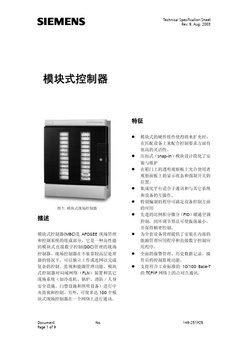
Technical Specification SheetRev. 9, Aug. 2003模块式控制器图1: 模块式现场控制器描述模块式控制器(MBC)是APOGEE现场管理和控制系统的组成部分,它是一种高性能的模块式直接数字控制(DDC)管理的现场控制器。
现场控制器在不依靠较高层处理器的情况下,可以独立工作或连网以完成复杂的控制、监视和能源管理功能。
模块式控制器对局域网络(FLN)装置和其它现场系统(如冷冻机、锅炉、消防/人身安全设施、门禁设施和照明设备)进行中央监视和控制。
另外,可使多达100个模块式现场控制器在一个网络上进行通讯。
特征模块式的硬件组件使得将来扩充时,在匹配设备上来配合控制要求方面有很高的灵活性。
压扣式(snap-in)模块设计简化了安装与维护在箱门上的透明观察板上允许使用者观察面板上的显示状态和强制开关的位置。
集成化平台适合于通讯和与其它系统和设备的互操作。
特别编制的程序可满足设备控制方面的应用先进的比例积分微分(PID)暖通空调控制,闭环调节算法可使振荡最小,并保持精密控制。
为全套设备管理提供了安装在内部的能源管理应用程序和直接数字控制应用程序。
全面的报警管理、历史数据记录、操作员的控制监视功能。
支持符合工业标准的10/100 Base-T 的TCP/IP网络上的点对点通讯。
Technical Specification SheetRev. 9, Aug. 2003线路电源维修工具盒瞬变电流抑制和过载保护模块式监控点配置根据用户需求配置点类型和数量,来配合应用的需要 备有多种箱体尺寸,以配合点数和将来扩展的需求搭扣式(Snap-in)点终端模块分为两部份的点模块/接线组允许阶段安装,而且维修人员无需再接线,不使用任何工具即可进行维护 各模块配有独立电路,某处出现故障时,系统的其余部份并不受影响利用表面安装技术实现了小型化,可更有效地利用空间 方便读取各监控点的卷标状态/强制能力备有手动监控强制开关选项,可对输出进行控制和维护 易于看到各监控点的LED 指示灯显示,即使门关闭时也如此 强制状态点在报告中显示操作强制开关时不需动用开放式处理器(需动用电源供应器模块)模块总线点终端模块和开放式处理器之间的通讯 以62.5K bps 速率扫描监控点终端模块总线结构允许监控点终端模块以任何次序安装电源模块为点终端模块提供24Vac 和24Vdc 的电流 独立模块结构使安装和维修更方便 过压/电压不足保护及过电流保护开放式处理器具有16.67MHz 速度的摩托罗拉68302处理器,可提供快速处理 可扩充的内存能配合数据/程序储存的需要现场可编程固件使更新变得简单易行,而无须更换底板两个快速连接(RJ-11)操作终端端口用于网络的信息通讯、调制解调器支持和打印可增加调制解调器选项,以便通过电话进行通信 管理网络上的点对点通讯协调楼宇网络(FLN)设备的传输,其内容包括时间安排、警报和强制 可任意选择与其它各现场系统控制器的通讯超强处理器可提供跨TCP/IP 以太网的点对点通讯 通讯汇流 符合SCSI 工业标准 高达6M bps 速率的控制器间通讯分配24Vac 电流给电源模块和开放式处理器图2: 模块式现场控制器组件和主要特点硬件组件模块式控制器由以下四个主要部份组成:箱体组件-根据箱体内部组件的情况,有两种型号供选择。
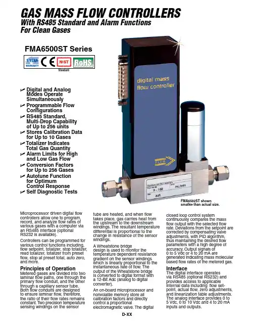
U D igital and Analog Modes Operate Simultaneously U P rogrammable Flow Configurations U R S485 Standard,Multi-Drop Capability of Up to 256 units U S tores Calibration Data for Up to 10 Gases U T otalizer Indicates Total Gas Quantity U A larm Limits for High and Low Gas Flow U C onversion Factors for Up to 256 Gases U A utotune Function for OptimumControl Response U Self Diagnostic TestsMicroprocessor driven digital flow controllers allow one to program, record, and analyze flow rates of various gases with a computer via an RS485 interface (optional RS232 is available).Controllers can be programmed for various control functions including, flow setpoint, totalizer, stop totalizer, read totalizer, totalizer from preset flow, stop at preset total, auto zero, and more.Principles of OperationMetered gases are divided into two laminar flow paths, one through the primary flow conduit, and the other through a capillary sensor tube. Both flow conduits are designed to ensure laminar flow, therefore, the ratio of their flow rates remains constant. T wo precision temperature sensing windings on the sensortube are heated, and when flow takes place, gas carries heat from the upstream to the downstream windings. The resultant temperature differential is proportional to the change in resistance of the sensor windings.A Wheatstone bridgedesign is used to monitor thetemperature dependent resistance gradient on the sensor windings which is linearly proportional to the instantaneous rate of flow. The output of the Wheatstone bridge is converted to digital format with a 12-Bit Adc (analog to digital converter).An on-board microprocessor and nonvolatile memory store all calibration factors and directly control a proportionalelectromagnetic valve. The digitalclosed loop control systemcontinuously compares the mass flow output with the selected flow rate. Deviations from the setpoint are corrected by compensating valve adjustments, with PID algorithm, thus maintaining the desired flow parameters with a high degree of accuracy. Output signals of 0 to 5 Vdc or 4 to 20 mA aregenerated indicating mass molecular based flow rates of the metered gas.InterfaceThe digital interface operates via RS485 (optional RS232) and provides access to applicable internal data including: flow set-point, actual flow, zero adjustments, and linearization table adjustments. The analog interface provides 0 to 5 Vdc, 0 to 10 Vdc and 4 to 20 mA inputs and outputs.FMA6502ST shownsmaller than actual size.FMA6500ST Seriesgas Mass Flow Controllerswith rs485 standard and alarm FunctionsFor Clean gasesDContact ClosureT wo sets of dry contact relay outputs are provided to actuateuser supplied equipment. These are programmable via the digital interface such that the relays can be made to switch when a specified event occurs (e.g. when a low or high flow alarm limit is exceeded or when the totalizer reaches a specified value).Valve OverrideMeans are provided to force the control valve fully open (purge) or fully closed via either the analog or digital interfaces.Self DiagnosticsWhenever power is first applied, the FMA6500ST runs a series of self diagnostic tests to ensure that it is in optimum working condition.Engineering UnitsThe flow setpoint, measured gasflow and associated totalizer data is scaled directly in engineering units via digital interface com-mands. The following units of measure are supported: % of FS, mL/min, mL/hr, scfm, scfh, sL/min, sL/hr, lbs/hr, lbs/min, and one user defined unit of measure.Leak Integrity1 x 10-9 smL/sec of helium maximum to the outside environment.Balanced Power SupplyThe FMA6500ST operates on±15 Vdc. The current requirements for the positive and negative power supplies are balanced such that the current in the power supply common connection is minimized. Maximum power consumption is 13.5 watts at ±15 Vdc.Auto ZeroThe FMA6500ST automatically nulls the sensor zero offsetwhenever the flow setpoint is below 2% FS. T o accommodate this feature the control valve must fully close under that condition. Provisions are made to either disable, force, or store thecurrent auto zero via digital commands.TotalizerThe firmware for the FMA6500ST provides functions to register total gas quantity. The total mass of gas is calculated by integrating the actual gas flow rate with respect to time. Digital interface commands areprovided to: set the totalizer to zero, start/stop totalizing the flow, read the totalizer, start the totalizer at a preset flow, and stop the flow at a preset total.Multi-Gas Calibration Option The FMA6500ST is capable of storing primary calibration data for up to 10 gases. This feature allows the same FMA6500ST to be calibrated for multiple gases while maintaining the rated accuracy on each.Standard 10-Point NIST CalibrationOptional up to 9 additional 10-point calibration may be ordered at an additional cost per gas.Conversion FactorsConversion factors for up to 256 gases are stored in the FMA6500ST .Conversion factors may be applied to any of the ten gas calibrations via digital interface commands.Flow AlarmsHigh and Low gas flow ALARM limits are programmed using the digital interface. Alarm conditions are reported via the digital interface or can activate the contact closure outputs.Programmable FlowOMEGA ® software supportsprogrammable flow modes, allowing execution of custom programmingof up to ten steps. Various flowconfigurations include ramping,linearized increasing, anddecreasing modes.AutotuneThe autotune function allows theFMA6500ST to automaticallyoptimize control response for the gas under actual process conditions.During the autotune process, theinstrument adjusts PID gains foroptimum step response and deter-mine key control valve characteristics (only available on units with less than80 L/min maximum flow).FMA6502ST, shown smaller than actual size.SPECIFICATIONSAccuracy (including linearity):15 to 25°C (59 to 77°F) and 0.7 to 4 bar (10 to 60 psia): ±1% of FS, 0 to 50°C(32 to 122°F) and 0.3 to 10 bar (5 to 150 psia): ±2% of FS, ±1% of FS at a specific temperature and pressure with special calibration Repeatability: ±0.15% FS Turndown Ratio: 50:1Response Time: 0.6 to 1.0 s to within ±2% of setpoint over 20% to 100% FS Temperature Coefficient: 0.05% of full scale/°C or betterPressure Coefficient: 0.01% FS/psi (0.07 bar) or better Leak Integrity: 1 x 10⁻⁹ smL/sec Helium maximum to the outside environmentOptimum Gas Pressure:1.73 bar (25 psig)Maximum Gas Pressure: 34.5 bar(500 psig)Maximum Diff. Pressure: 3.4 bar (50 psig) for up to 10 LPM, 2.8 bar (40 psig) for 15 LPM and greaterGas and Ambient Temperature: 5 to 50°C (41 to 122°F)Output Signals: Linear 0 to 5 Vdc (2000 Ω min load impedance);0 to 10 Vdc (4000 Ω min impedance); 4 to 20 mA optional (0 to 500 Ω loop resistance)Communication Interface:RS485, standard; RS232, optional Transducer Input Power: ±15 Vdc, 450 mA maximumWetted Parts: 316 stainless steel, 416 stainless steel, FKM O-rings Neoprene or Perfluoroelastomer O-rings optionalConnections: Standard ¹⁄₄"compression fittings up to 30 LPMmodels; for 60 LPM models and greater: ³⁄₈" compression fittings Circuit Protection:Circuit boards have built-in polarity reversal protection; resettable fuses provide power input protection Calibration Options:Standard 10-point NIST calibration optional up to 9 additional 10-point calibrations may be ordered for a additional cost per gasFMA6500ST Controller Dimensions 15 LPM and GreaterFMA6500ST Controller Dimensions Up to 10 LPMDComes complete with operator’s manual, software, cable (FMA65-C), and NIST certificate. Power supply sold separately.* Specify gas or gases and inlet/outlet pressure. Calibrations done at ambient [20ºC (70ºF)] temperature only.** Flow ranges specified are for nitrogen or air at 20 psig inlet (up to 50 SLM) or 25 psig inlet (60 to 100 SLM units) and 0 psig outlet, see above ordering chart.For RS232 communications (replaces RS485), add suffix “-RS232” to model number, no additional cost.For 4 to 20 mA output (replaces 0 to 5V), add suffix “-I ” to model number, no additional cost.For Perfluoroelastomer O-rings (replaces FKM O-rings), add suffix “-K ” to model number, for additional cost.Ordering Examples: FMA6512ST , mass flow controller, and FMA65PWC power supply. FMA6542ST , mass flow controller, and FMA65PWC power supply.FMA65EPWC FMA65UKPWC FMA65-C15 FMA65-CAL-(*) FMA6502ST shown smallerthan actual size.。


pid控制器matlab仿真PID控制是最早发展的自动控制策略之一,PID控制系统由比例单元(P)、积分单元(I)和微分单元(D)组成。
具有简单易懂,使用中不需精确的系统模型等先决条件,因而成为应用最为广泛的控制器。
PID控制的参数自动调整是通过智能化调整或自校正、自适应算法来实现。
当被控对象的结构和参数不能完全掌握,或得不到精确的数学模型时,控制理论的其它技术难以采用时,系统控制器的结构和参数必须依靠经验和现场调试来确定,这时应用PID控制技术最为方便。
即当我们不完全了解一个系统和被控对象,或不能通过有效的测量手段来获得系统参数时,最适合用PID控制技术。
PID控制,实际中也有PI和PD控制。
PID控制器就是根据系统的误差,利用比例、积分、微分计算出控制量进行控制的。
本文首先从PID理论出发,建立模型,讨论系统的稳定性,快速性,准确性。
利用MATLAB对PID控制的参数进行仿真,设计不同的参数,以使系统满足所要求的性能指标。
2、控制领域有一个很重要的概念是反馈,它通过各种输出值和它们各自所需值的实时比较的度量―各种误差,再以这些误差进行反馈控制来减少误差。
这样形成的因果链是输入、动态系统、输出、测量、比较、误差、输入构成的一个环路,因而也构成了包含原动态系统在内的一个新的动态闭环系统。
采用反馈的基本原因是要在不确定性存在的条件下达到性能目标。
许多情况下,对于系统的了解是不全面的,或者可用的模型是基于许多简化的假设而使它们变得不透彻。
系统也可能承受外界干扰,输出的观测常受噪声干扰。
有效的反馈能减少这些不确定性的影响,因为它们可以补偿任何原因引起的误差。
反馈概括了很广泛的概念,包括当前系统中的许多回路、非线性和自适应反馈,以及将来的智能反馈。
广义的讲,反馈可以作为描述和理解许多复杂物理系统中发生的循环交互作用的方式。
在实际的过程控制和运动控制系统中,PID占有相当的地位,据统计,工业控制中PID 类控制器占有90%以上。

分散控制系统: 集散控制系统是以微处理器为基础,采用控制功能分散、显示操作集中、兼顾分而自治和综合协调的设计原则的新一代仪表控制系统。集散控制系统简称DCS,也可直译为“分散控制系统”或“分布式计算机控制系统”。 系统介绍: DCS通常采用分级递阶结构,每一级由若干子系统组成,每一个子系统实现若干特定的有限目标,形成金字塔结构。 可编程逻辑控制器 (可编程控制器件): 可编程逻辑控制器是种专门为在工业环境下应用而设计的数字运算操作电子系统。它采用一种可编程的存储器,在其内部存储执行逻辑运算、顺序控制、定时、计数和算术运算等操作的指令,通过数字式或模拟式的输入输出来控制各种类型的机械设备或生产过程。 简介: 可编程逻辑控制器(Programmable Logic Controller,PLC),一种具有微处理器的用于自动化控制的数字运算控制器,可以将控制指令随时载入内存进行储存与执行。可编程控制器由CPU、指令及数据内存、输入/输出接口、电源、数字模拟转换等功能单元组成。早期的可编程逻辑控制器只有逻辑控制的功能,所以被命名为可编程逻辑控制器,后来随着不断地发展,这些当初功能简单的计算机模块已经有了包括逻辑控制、时序控制、模拟控制、多机通信等各类功能,名称也改为可编程控制器(Programmable Controller),但是由于它 的简写PC与个人电脑(Personal Computer)的简写相冲突,加上习惯的原因,人们还是经常使用可编程逻辑控制器这一称呼,并仍使用PLC这一缩写。 现在工业上使用的可编程逻辑控制器已经相当或接近于一台紧凑型电脑的主机,其在扩展性和可靠性方面的优势使其被广泛应用于目前的各类工业控制领域。不管是在计算机直接控制系统还是集中分散式控制系统DCS,或者现场总线控制系统FCS中,总是有各类PLC控制器的大量使用。PLC的生产厂商很多,如西门子、施耐德、三菱、台达等,几乎涉及工业自动化领域的厂商都会有其PLC产品提供。
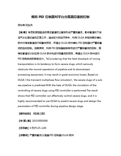
模拟 PID 控制器对平台分离器段塞的控制倪玲英;何生兵【摘要】考虑到混相输送极易在管道的立管段形成严重段塞流,影响管道和下游油气水处理设备的正常工作,造成巨大的经济损失,利用OLGA多相流瞬态模拟软件对海底管道进行段塞流预测,并通过OLGA软件模拟PID控制器对严重段塞流的自动控制。
结果表明,利用PID控制器能够有效进行严重段塞流的控制,推荐在管道设计时应用OLGA软件先进行段塞流的预测,再通过OLGA软件进行PID控制系统的参数设计。
%Considering that the fatal drawback of mixing transportation is its tendency to form severe slugs, which seriously obstructs the normal operations of pipeline and its downstream processing equipment, it may result in great economy losses. Based on OLGA ( the transient multiphase flow simulator) , the severe slugs of a sub-sea pipeline is predicted.With the help of OLGA, the simulation of the controlling of severe slugs using PID controller is performed.The result shows that PID controller can effectively control severe slugs, and it is highly recommended to use OLGA to predict severe slugs and design the parameters of PID controller during pipeline design stage.【期刊名称】《船海工程》【年(卷),期】2015(000)006【总页数】4页(P125-128)【关键词】严重段塞流;分离器;PID控制器;OLGA软件【作者】倪玲英;何生兵【作者单位】中国石油大学华东石油工程学院,山东青岛66580;中国石油大学华东石油工程学院,山东青岛66580【正文语种】中文【中图分类】U674.38;P752;TE88海洋地理环境特殊,通常利用采油平台进行海底油气资源的开发。
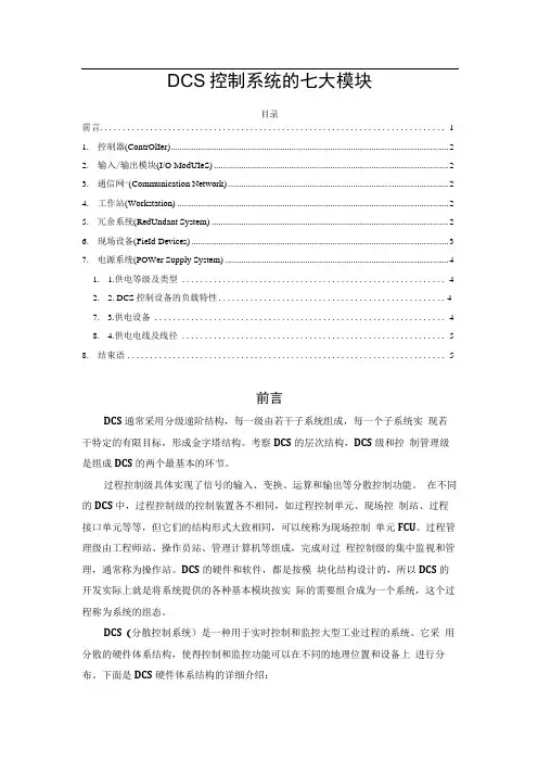
DCS控制系统的七大模块目录前言 (1)1.控制器(ContrOlIer) (2)2.输入/输出模块(I/O ModUIeS) (2)3.通信网^(Communication Network) (2)4.工作站(Workstation) (2)5.冗余系统(RedUndant System) (2)6.现场设备(FieId Devices) (3)7.电源系统(POWer Supply System) (4)1. 1.供电等级及类型 (4)2. 2. DCS控制设备的负载特性 (4)7. 3.供电设备 (4)8. 4.供电电线及线径 (5)8.结束语 (5)前言DCS通常采用分级递阶结构,每一级由若干子系统组成,每一个子系统实现若干特定的有限目标,形成金字塔结构。
考察DCS的层次结构,DCS级和控制管理级是组成DCS的两个最基本的环节。
过程控制级具体实现了信号的输入、变换、运算和输出等分散控制功能。
在不同的DCS中,过程控制级的控制装置各不相同,如过程控制单元、现场控制站、过程接口单元等等,但它们的结构形式大致相同,可以统称为现场控制单元FCU。
过程管理级由工程师站、操作员站、管理计算机等组成,完成对过程控制级的集中监视和管理,通常称为操作站。
DCS的硬件和软件,都是按模块化结构设计的,所以DCS的开发实际上就是将系统提供的各种基本模块按实际的需要组合成为一个系统,这个过程称为系统的组态。
DCS(分散控制系统)是一种用于实时控制和监控大型工业过程的系统。
它采用分散的硬件体系结构,使得控制和监控功能可以在不同的地理位置和设备上进行分布。
下面是DCS硬件体系结构的详细介绍:1.控制器(ContrOller)DCS的控制器是系统的核心部分,负责执行控制任务和处理过程数据。
控制器通常由一台或多台计算机组成,可以是工作站、服务器或嵌入式计算机。
控制器运行DCS 软件,接收来自输入/输出模块的数据,并根据预先编写的控制策略进行逻辑运算和决策。
无人机模拟控制技巧无人机模拟控制技巧无人机模拟控制是无人机飞行员必备的技能之一。
通过模拟控制,飞行员可以在安全的环境下练习各种飞行技巧,提高自己的飞行水平。
以下是一些无人机模拟控制技巧,希望对大家有所帮助。
1. 熟悉无人机控制器在模拟控制之前,飞行员需要先熟悉无人机控制器的各个按钮和开关的功能。
这样可以更加快速地做出反应,避免出现误操作。
2. 练习起飞和降落起飞和降落是无人机飞行中最基本的技能。
在模拟控制中,飞行员可以反复练习起飞和降落,熟悉无人机的起飞和降落流程,提高自己的操作技能。
3. 练习悬停悬停是无人机飞行中的一项重要技能。
在模拟控制中,飞行员可以练习悬停,熟悉无人机的悬停操作,提高自己的悬停技能。
4. 练习飞行姿态调整飞行姿态调整是无人机飞行中的一项重要技能。
在模拟控制中,飞行员可以练习飞行姿态调整,熟悉无人机的姿态调整操作,提高自己的姿态调整技能。
5. 练习飞行路线规划飞行路线规划是无人机飞行中的一项重要技能。
在模拟控制中,飞行员可以练习飞行路线规划,熟悉无人机的路线规划操作,提高自己的路线规划技能。
6. 练习飞行模式切换飞行模式切换是无人机飞行中的一项重要技能。
在模拟控制中,飞行员可以练习飞行模式切换,熟悉无人机的模式切换操作,提高自己的模式切换技能。
7. 练习飞行器件故障处理飞行器件故障处理是无人机飞行中的一项重要技能。
在模拟控制中,飞行员可以练习飞行器件故障处理,熟悉无人机的故障处理操作,提高自己的故障处理技能。
总之,无人机模拟控制是无人机飞行员必备的技能之一。
通过模拟控制,飞行员可以在安全的环境下练习各种飞行技巧,提高自己的飞行水平。
希望以上技巧对大家有所帮助。
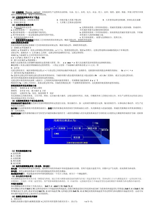
自动控制仪表简述一.自动控制仪表的作用自动控制是指再没有人直接参与的情况下,利用控制装置(控制器),使机器、设备或生产过程(被控对象)的某一工作状态或参数(被控量)自动按照预定的规律运行。
自动控制是可以在检测的基础上,在应用控制仪表(常称为控制器)和执行器来代替人工操作。
自动控制仪表在自动控制系统中的作用是将被控变量的测量值与给定值相比较,产生一定的偏差,控制仪表根据该偏差进行一定的数学运算,并将运算结果以一定的信号形式送往执行器,以实现对于被控变量的自动控制。
二.自动控制仪表的分类及其特点1.按控制仪表的结构形式分类(1)基地式控制仪表⑴原理:基地式控制仪表是将测量、变送、显示及控制等功能集于一身的一种控制仪表。
它的结构比较简单,常用于简单控制系统。
⑵目前流行的仪表:有MOOR公司的XCT340 D-B、SMAR公司的LD301和KF系列。
⑶存在的问题:①气动基地式仪表(例如KF系列)要比电动基地式仪表的价格贵l倍还要多;②目前电动基地式仪表还未国产化,尚需进口;③气动基地式仪表对气源质量要求高。
往往由于气源净化不好而不能投入自动。
⑷发展方向:电动基地式仪表的发展趋势是全部采用现场总线技术,将一些本属于控制室中控制器的功能下放到现场型仪表中,从而更加拓宽了其使用范围。
不但简化了系统,节约了投资。
而且利用现场总线的双向通信功能,可由现场向控制室发出测量参数、维修预报以及故障诊断等信号,同时,也可在控制室对电动基地式仪表进行在线组态、设定、维护及调整。
(2)单元组合式仪表⑴原理:单元组合式仪表把整套仪表按照其功能和使用要求,分成若干独立作用的单元,个单元之间用统一的标准信号联系,使用时,针对不同的要求,将个单元以不同的形式组合,可以组成各种各样的自动检测和控制系统。
图1-1用电动单元组合仪表构成的调节系统⑵单元组合式仪表的分类(按使用的能源来分)①气动单元组合式仪表:以电作为能源及传送信号的仪表.这种仪表具有响应快速,易于控制和远距离传送,便于与各种电子装置、计算机等配合,可构成各种复杂的综合控制系统,发展十分迅速,在生产中被广泛应用。
§6 模糊控制原理简介§6。
1 模糊控制系统现代控制理论已经在工业、国防、航天等许多领域获得了成功。
一般情况下,传统的闭环控制系统如图6。
1所示,其原理是建立在精确的数学模型上。
但对于一些强藕合、多参数、非线性、时变性、大惯性、纯滞后的复杂系统,建立它们的精确数学模型是很困难的,有些甚至是不可能的。
然而,在实际工作当中,一些有经验的操作人员却可以通过观察、推理和决策,用人工控制的方法较好地控制那些复杂的对象。
模糊控制系统就是将人的经验总结成语言控制规则,运用模糊理论模拟人的推理与决策,从而实现自动控制的控制系统。
模糊控制系统与传统的闭环控制系统不同之处,就是用模糊控制器代替了模拟式控制器,其硬件结构框图如图6.2所示。
输出y(t)输出y(t)图6.1 图6.2输出图6。
3§6。
2 模糊控制器的设计模糊控制器本质上就是一个采用了模糊控制算法的计算机或芯片,其一般结构如图6。
3所示。
它由三个基本部分构成:(1)将输入的确切值“模糊化”,成为可用模糊集合描述的变量;(2)应用语言规则进行模糊推理;(3)对推理结果进行决策并反模糊化(也称为清晰化、解模糊),使之转化为确切的控制量。
有m个输入一个输出的模糊控制器称为m维模糊控制器。
由于一维模糊控制器所能获得的系统动态性能往往不能令人满意,三维及三维以上的模糊控制器结构复杂,推理运算时间长,因此典型的模糊控制器是二维模糊控制器。
一般地,设计一个二维的模糊控制器,通常需要五个步骤:1.确定输入变量与输出变量及其模糊状态;2.输入变量的模糊化;3. 建立模糊控制规则;4. 进行模糊推理;5. 输出变量的反模糊化。
6。
2。
1 确定输入变量与输出变量及其模糊状态根据问题的背景,确定出输入变量E 1、E 2和输出变量u 。
输入、输出变量的模糊状态按照控制品质的要求可分为三类:控制品质要求较高的场合,变量的模糊状态取为负大(NB )、负中(NM)、负小(NS)、零(ZO )、正小(PS)、正中(PM )、正大(PB )或负大(NB )、负中(NM)、负小(NS)、负零(NZ)、正零(PZ )、正小(PS)、正中(PM )、正大(PB );控制品质要求一般的场合,变量的模糊状态取为负大(NB )、负小(NS )、零(ZO )、正小(PS )、正大(PB)或负大(NB )、负小(NS )、负零(NZ)、正零(PZ)、正小(PS )、正大(PB);控制品质要求较低的场合,变量的模糊状态取为负大(NB )、零(ZO)、正大(PB )或负大(NB )、负零(NZ )、正零(PZ)、正大(PB )。
探索控制器的手柄模式与键鼠模拟功能游戏控制器是玩游戏时不可缺少的工具之一。
随着技术的不断发展,控制器的种类也越来越多。
其中,手柄模式和键鼠模拟功能是比较常见的两种。
本文将探讨这两种模式以及它们在游戏中的作用。
手柄模式手柄是最常用的游戏控制器之一。
它的外观类似于一个小型游戏机,有两个摇杆、几个按钮和一个方向键。
玩家可以通过手柄进行游戏,操作比较简单。
手柄模式最大的优点是可玩性高。
通过手柄,玩家可以更加真实地感受到游戏的画面和音效,同时也能更好地掌握游戏的节奏。
如果你是一个第一人称射击游戏爱好者,使用手柄也有很多优点。
手柄的双摇杆和按键可以让你更加灵活地移动,也能更快地反应游戏中的变化。
总体来说,手柄模式适合那些玩家,他们喜欢更加真实地感受游戏的过程。
键鼠模拟功能键鼠模拟功能是指在控制器上模拟键盘和鼠标的功能。
通常,这种功能需要使用第三方软件才能实现。
通过键鼠模拟功能,玩家可以使用控制器操作游戏,但其体验却与使用真正的键盘和鼠标一样。
键鼠模拟功能的最大优点是玩家可以更加精准地操作游戏。
在许多游戏中,如RTS(即时战略游戏)和MOBA(多人在线战术游戏),使用键鼠可以获得更高的胜率。
这是因为键鼠能够让玩家更加快速和准确地控制游戏中的单位或角色。
如果你是一个玩这些游戏的高手,你可能希望使用键鼠模拟功能来提高自己在游戏中的表现。
结论手柄模式和键鼠模拟功能都有自己的用途。
选择哪种模式应该完全取决于玩家的个人喜好和游戏类型。
更真实的体验和更好的可玩性是手柄模式的两个主要优点,而精准度和更高的胜率是键鼠模拟功能的优点。
在选择游戏控制器时,玩家应该在这两种模式之间进行权衡,并选择适合自己游戏需求的控制器。