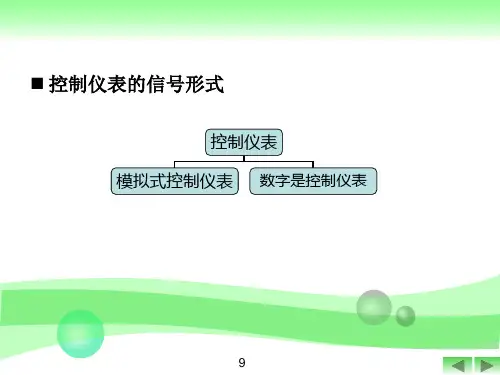
模拟式控制器
- 格式:pptx
- 大小:2.78 MB
- 文档页数:2
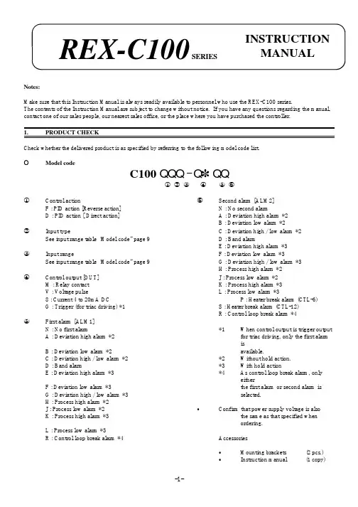
Notes:Make sure that this Instruction Manual is always readily available to personnel who use the REX-C100 series.The contents of the Instruction Manual are subject to change without notice. If you have any questions regarding the manual,contact one of our sales people, our nearest sales office, or the place where you have purchased the controller.1.PRODUCT CHECKCheck whether the delivered product is as specified by referring to the following model code list.OModel codeC100 QQQ - Q ~ QQÎ Ï Ð Ñ Ò ÓÎControl actionÓSecond alarm [ALM2]F : PID action [Reverse action]N : No second alarmD : PID action [ Direct action]A : Deviation high alarm *2B : Deviation low alarm *2ÏInput typeC : Deviation high / low alarm *2See input range table “Model code” page 9D : Band alarmE : Deviation high alarm *3ÐInput rangeF : Deviation low alarm *3See input range table “Model code” page 9G : Deviation high / low alarm *3H : Process high alarm *2ÑControl output [OUT]J : Process low alarm *2M : Relay contact K : Process high alarm *3V : Voltage pulseL : Process low alarm *38 : Current 4 to 20mA DCP : Heater break alarm (CTL-6)G : Trigger (for triac driving) *1S : Heater break alarm (CTL-12)R : Control loop break alarm *4ÒFirst alarm [ALM1]N : No first alarm*1When control output is trigger output A : Deviation high alarm *2for triac driving, only the first alarm isB : Deviation low alarm *2available.C : Deviation high / low alarm *2*2Without hold action.D : Band alarm*3With hold actionE : Deviation high alarm *3*4As control loop break alarm, only eitherF : Deviation low alarm *3the first alarm or second alarm is G : Deviation high / low alarm *3selected.H : Process high alarm *2J : Process low alarm *2CConfirm that power supply voltage is alsoK : Process high alarm *3the same as that specified when ordering.L : Process low alarm *3R : Control loop break alarm *4Accessories C Mounting brackets (2 pcs.)CInstruction manual(1 copy)REX-C100SERIESINSTRUCTION MANUALFig. 1Fig. 22.MOUNTING •DimensionsUnit : mm (inch)* Dimensions in inches are shown for reference•Mounting proceduresThickness of panel board:1 to 5mm or 5 to 9mm (0.04 to 0.20 inch or 0.20 to 0.35 inch)uWhen the controllers are mounted on panel with 1 to 5mm in thickness ÎMake a rectangular cutout corresponding to thenumber of controllers to be mounted on panel by referring to the panel cutout dimensions.ÏSince the mounting brackets are already installed onthe controller, insert the controller into the panel from the panel front without removal of the brackets (Fig. 1).uWhen the controllers are mounted on panel with 5 to 9m in thickness ÎRemove the mounting brackets from the controllerwith a slotted screwdriver.ÏEngage each mounting bracket with holes markedwith “5.9" on the housing (Fig. 2) and then insert the controller into the panel from the panel front.OCautions for mountingMo untingbracketAvoid the following location where the controller is mounted.C Location where ambient temperature is more than 50E C (122E F) or less than 0E C (32E F).C Location where humidity is high.C Location where corrosive gas is generated.C Location where strong vibration and shock exist.C Location where flooding and oil splash exist.C Location where much dust exists.CLocation where inductive disturbance is large and otherlocation where bad influence is exerted on electric instrument.3.WIRING•Rear terminalsNotes1.Terminals which are not used according to the controller type are all removed.2.For thermocouple input, no metal piece is attached to terminal No. 10. Instead, the temperature compensationelement in the internal assembly is projected through a hole at terminal No. 10.Do not damage the above temperature compensation element when the internal assembly is removed from the case.O Cautions for wiring(1)Conduct input signal wiring away from instrument, electric(3)For wiring, use wires conforming to domesticequipment power and load lines as such as possible to avoid standard of each country.noise induction.(4)About 5 to 6 sec. are required as the(2)Conduct instrument power wiring so as not to be influenced preparation time of contact output duringby noise from the electric equipment power.power ON. Use a delay relay whenthe outputIf it is assumed that a noise generation source is located near line, is used for an external interlock circuit.the controller and the controller is influenced by noise, use anoise filter (select the filter by checking instrument power(5)The figures below show the REX-C100 circuit supply voltage.)configuration. When connecting wires, notethat the power, input, MCU and output circuitsC Sufficient effect may not be obtained depending on the are isolated independently, while the inside offilter. Therefore, select the filter by referring to its the input and outputcircuits are not isolated.frequency characteristic, etc.ÎFor instrument power wiring, if it is assumed that noiseexerts a bad influence upon the controller, shorten thedistance between twisted power supply wire pitches.(The shorter the distance between the pitches, the moreeffective for noise reduction).ÏInstall the noise filter on the panel which is alwaysgrounded and minimize the wiring distance between thenoise filter output side and the controller power terminals.Otherwise, the longer the distance between output sideand instrument power terminals, the less effective for REX-C100 circuit configurationnoise.ÐDo not install fuses and / or switches on the filter outputsignal since this may lessen filter effect.WIRING AND NAME OF PARTS•Wiring exampleREX-C100F GG-M*-~2N-HA OF PARTSÑSet-value increment keyC Used when the number needs to be increasedfor set-value change.ÒMeasured-value (PV) display unit [Green]C Displays measured-value (PV)C Displays a parameter symbol in the parametersetting mode.ÓSet-value (SV) display unit [Orange]C Displays set-value (SV)C Displays set-value corresponding to theparameter symbol displayed on the measured-value (PV) display unit.ÎSet (SET) keyC The set-value thus changed is enteredÔControl output (OUT) lamp [Green]C Parameters in the parameter setting mode are C Lights up when the control output is turnedON.selected in due order.C Can select PV / SV display mode, SV settingÕAuto-tuning (AT) lamp [Green]mode, and parameter setting modes.C Flashes during auto-tuning.ÏSetting digit shift keyÖFirst alarm (ALM1) lamp [Red]C Used when the cursor (brightly lit) is moved to C Lights up when the first alarm is turned ON.the digit whose number needs to be changed for C When a control loop break alarm (LBA) is set-value change.selected as the first alarm, this lamp lights up.ÐSet-value decrement key×Second alarm (ALM2) lamp [Red]C Used when the number needs to be decreased C Lights up when second alarm is turned ON.for set-value change.C When either a heater break alarm (HBA) orcontrol loop break alarm (LBA) is selected asthe second alarm, this lamp lights up.5.OPERATION•Calling-up procedure of each mode:Press the key.Input type code / input range displayThis controller, with the power turned ON, displaysautomatically the input type code on the measured-value (PV)display unit and the input range, on the set-value (SV) displayunit, respectively.Example : For a controller with the K thermocouple inputtype and input range from 0 to 1372E C.ÎDisplays the input type code.: Indicates input abbreviation.unit. ( : E F)input type code table).ÏDisplays the input range.< Input type code >Code Input Type Code Input typeRSBW5Re/W26RePLIIPt100JPt100PV / SV display modeC Displays measured-value (PV) on the measured-value(PV) display unit and set-value (SV) on the set-value (SV)display unit. Usually the control is set to this modeexcepting that the set-value (SV) and/or the parameter set-value are changed.PV / SV display modeC Pressing the key lights the least significant digit onvalue (SV).In order to register the value whose setting was changed,always press the key after the value is changed.sec. in the PV / SV display or SV setting mode, thecontroller is set to the parameter setting mode.C Parameters in the parameter setting mode changes in dueorder every time the key is pressed (See page 6).and keys are pressed.C In order to register the value whose setting was changed,press the key after change to shift to the nextsec.•When no key is operated for more than 1 minute.•Parameter typesThe following parameter symbols are displayed one by one every time the key is pressed.Current transformer input (CT)Setting is not possible.Set heater break alarm value byreferring to this value.Display input value from thecurrent transformerCTSecond alarm Set alarm set-value of second alarm.AL2Control loopbreak alarm (LBA)0.0 to 200.0 min.Set control loop break alarmset-value.Cannot be set to “0.0".8.0LbAAuto-tuning (AT)0 : Auto-tuning end or stop1 : Auto-tuning startTurns the auto-tuningON/OFF.ATUIntegral time (I)1 to 3600 sec.Eliminates offset occurringcontrol is performed. I actionturns OFF with I set to “0".240IAnti-reset windup (ARW)1 to 100% of proportional band.Prevents overshoot and/orundershoot caused by integralaction. I action turns OFFwith this action set to “0".100ArSet data lock 0100 : No set data locked (Allparameters changeable)0101 : Set data locked (All parametersnot changeable)0110 : Only the set-value (SV) ischangeable with the set data locked.Performs set data changeenable / disable.0100LCK* The second alarm (or first alarm), heater break alarm, control loop break alarm parameter symbols are not simultaneously displayed. * Heater break alarm is not available on a current output.C Parameter setting procedure Setting set-value (SV)Following is an example of setting the set-value (SV) to 200E C. (PV : 30E C)Î Set to the set modeÏ Shift of the digit brightly litÐ Set-value increase or decrease ÑSet-value entryPress the key to Press the key to shift Press the key to set “2".After finishing the setting,enter the SV setting mode.the digit which lights brightlypress thekey. All ofController returns to the PV/SV display mode.Example : When a temperature of 199E C is changed to 200E C.Set-value increase or decreasePress the key to shift the digit brightly lit to the least significant digit. Press the key to change “9" to “0", therebyobtaining 200E C. The same applies to set-value decrease.Example : For changing 200 to -100.Minus (-) value settingPress the key to shift the digit brightly lit to the hundreds digit. Press the key to decrement figures in order of÷ 0 ÷ -1.Setting parameters other than set-value In the PV/SV display modeIn the parameter setting modeKey operational cautions CFor this controller, the value whose setting was changed is not registered. It is registered for the first time it is shifted to the next parameter by pressing the key.setting mode, set data lock is activated.In this case, change the “” parameter set-value to “0100".the parameter setting mode.Press thekey by the required number of times untilkey after the setting is finished in the parameters).When no parameter setting is required, return the controller to the PV/SV display mode.¬Pay attention to the following when the parameters described below are set.Auto-tuning (AT)C Prior to starting the auto-tuning function, end all the parameter settings other than PID and control loop break alarm(LBA).Heater break alarm (HBA)C Set heater break alarm set-value to a value about 85% current transformer input value. However, when power supplyvariations are large, set the alarm to a slightly smaller value.In addition, when two or more heaters are connected in parallel, set the alarm to a slightly larger value so that it is activated even with only one heater is broken. (However, within the value of a current transformer input value).C When the heater break alarm set-value is set to “0.0" or the current transformer is not connected, the heater breakalarm is turned ON.Control loop break alarm (LBA)C Usually set the set-value of the LBA to a value twice the integral time (I).O Set data locking procedureThis controller is provided with a set data locking function which disables each set-value change by the front key and also the auto-tuning function. Use this function for malfunction prevention at the end of each setting.C Press the key by the required number of(PV) display unit.C Press the , and keys to set the•Display at error occurrence< Heater break alarm >Display CauseMeasure(Lights)C Controlled object trouble (No power supply,incorrect wiring, etc).C Sensor trouble (Sensor disconnected, shorted, etc).C Actuator trouble (Weld relay contact, incorrectwiring, relay contact not closed, etc).C Output circuit trouble (Weld internal relay contact,relay contact not opened or closed, etc).C Input circuit trouble (The measured-value does notchange even if input changes, etc).Control system check(Error cause cannot bespecified)Check whether there is no effectby disturbances (Other heatsource, etc).LBA set time check< Overscale, Underscale >Input type Input display rangeTCK-30 to +1372E C -30 to +2502E F J-30 to +1200E C -30 to +2192E F R, S-30 to +1769E C -30 to +3216E F B-30 to +1820E C -30 to +3308E F E-30 to +1000E C -30 to +1832E F T-199.9 to +400.0E C -199.9 to +752.0E F N-30 to +1300E C -30 to +2372E F PLII-30 to +1390E C -30 to +2534E F L-30 to +800E C -30 to +1600E F U-199.9 to +600.0E C -199.9 to +999.9E F W5Re/W26Re-30 to +2320E C -30 to +4000E FRTDPt100JPT100-199.9 to +649.0E C Pt100-199.9 to +999.9E F。

舞台灯光知识:灯光控制器的使用技巧及接线方法舞台灯光是演出的重要组成部分,控制好灯光能够让演出更加生动、丰富,对于一名灯光师来说,熟练掌握灯光控制器的使用技巧及接线方法是至关重要的。
本文将围绕这一主题展开,希望能帮助读者更好地了解灯光控制器的使用方法。
一、灯光控制器的种类灯光控制器是控制舞台灯光的设备,根据不同的功能和特点,可分为模拟控制器、数字控制器、DMX控制器等。
1.模拟控制器模拟控制器是早期使用比较多的控制器,它是通过调节电阻、电容等元件来实现对灯光的控制。
因为其控制范围和功能比较有限,所以目前已经渐渐被数字控制器所替代。
2.数字控制器数字控制器是通过计算机软件来控制灯光,具有控制范围广、控制功能强大的特点。
它也可以通过手机APP或者遥控器等多种方式进行控制,使用方便。
3. DMX控制器DMX控制器是一种数字控制器,它通过DMX信号来控制舞台灯具。
DMX信号是一种数字信号,可以支持多种灯光控制功能,同时减少了布线的难度。
二、灯光控制器的使用技巧灯光控制器的使用技巧对于灯光师来说非常关键,下面我们将介绍一些使用灯光控制器的技巧。
1.灯光的预设在演出前,灯光师需要根据演出的需要,预设好舞台上的灯光效果。
这需要灯光师熟悉控制器的操作,将需要控制的灯光效果预先调好。
2.节奏感节奏感是控制好灯光的关键之一,灯光师需要根据舞台上演出的音乐或者舞蹈节奏,将灯光的变换设置好。
要注意灯光的变换要与演出内容相呼应,形成和谐的整体效果。
3.色彩搭配色彩搭配也是灯光师需要特别注意的,灯光师需要根据演出内容、舞台布景等因素来选择合适的灯光颜色。
色彩的搭配要注意不要过于单调,要形成丰富多彩的视觉效果。
三、灯光控制器的接线方法灯光控制器的接线方法对于使用者来说也非常重要,下面我们将介绍一些常见的接线方法。
1. DMX控制器的接线方法DMX控制器的接线方法相对较为简单,只需要把DMX信号线连接到灯光师调整器的DMX输入口上即可。
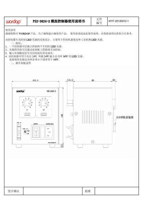
PS2-3624-2模拟控制器使用说明书文件WYF-20140912-1编号使用说明感谢您购买WORDOP产品。
为了确保能正确使用产品,使用前请阅读此使用说明,并保留说明以供您日后参考。
该控制器专为控制LED光源的亮度设计。
主要用于控制机器视觉和工业检测LED光源。
一、特征:1.一个控制器可以独立控制两个不同的LED光源。
2.光源的亮度可以通过前面板上的旋钮手动控制。
3.输入外部触发信号可以控制灯的亮或灭。
4. 该控制器可用于电压24V, 单路24W最大总功率36W的LED光源。
连接使用光源总功率必须小于或者等于36W。
二、操作面板说明签字确认批准三、规格参数型号PS2-3624-4发光方式常时发光/无级调光驱动方式恒压通道数2通道输入电压(额定)AC100V~240V触发功能有触发输入电压5~24V输出总功率(额定) 2通道合计36W输出电压(额定)DC24V输出电流(额定)单通道合计1.0A发光延时5us MAX使用环境温度0--40°C 湿度20--85%RH(无结霜状态)储存环境温度-20--60°C 湿度20--85%RH(无结霜状态)冷却方式自然空气冷却材质·表面处理SPCC 表面喷漆处理重量1KG标配配件触发线、AC电源线可选配件调光设定手动旋钮无级调光ON/OFF设定外部高低电平触发输入签字确认批准安装方法安装时:将连接器完全插入灯的连接插头移除时:解开锁扣然后拉出连接器从控制器底部取下橡胶脚垫,用螺丝刀将固定橡胶脚垫的螺丝取下来。
固定支架到底座,用支架带的四个螺丝将支架固定到底座上。
用安装螺丝固定控制器,用安装螺丝将控制器固定到正确的位置,安装螺丝由用户自备。
移除时:按住锁扣然后拉出连接器。
VisualField系统软件控制器仿真软件使用手册浙江中控技术股份有限公司声 明⏹ 严禁转载本手册的部分或全部内容。
⏹ 在不经预告和联系的情况下,本手册的内容有可能发生变更,请谅解。
⏹ 本手册所记载的内容,不排除有误记或遗漏的可能性。
如对本手册内容有疑问,请与我公司联系。
文档标志符定义警告:标示有可能导致人身伤亡或设备损坏的信息。
WARNING : Indicates information that a potentially hazardous situation which, if not avoided, could result in serious injury or death.电击危险:标示有可能产生电击危险的信息。
Risk of electrical shock: Indicates information that Potential shock hazard where HAZARDOUS LIVE voltages greater than 30V RMS, 42.4V peak, or 60V DC may be accessible.防止静电:标示防止静电损坏设备的信息。
ESD HAZARD: Indicates information that Danger of an electro-static discharge to which equipment may be sensitive. Observe precautions for handling electrostatic sensitive devices注意:提醒需要特别注意的信息。
ATTENTION: Identifies information that requires special consideration.提示:标记对用户的建议或提示。
TIP :Identifies advice or hints for the user.目录控制器仿真软件 (1)1 概述 (1)2 启动控制器仿真软件 (2)3 主界面 (3)3.1 标题栏/状态栏 (3)3.2 菜单栏/工具栏 (3)3.3 主视窗口/输出窗口 (4)4 使用说明 (5)4.1 运行/暂停/停止 (5)4.2 存档/载入存档 (5)4.3 断点 (6)4.4 执行周期倍率设置 (9)4.5 内存浏览器 (10)4.6 最简模式/正常模式切换 (11)4.7 模拟电池 (11)5 仿真控制器状态 (12)6 控制器基本信息 (13)7 虚拟网卡设置 (14)7.1 添加虚拟网卡 (14)7.1.1 Windows XP (14)7.1.2 Windows 7 (21)7.2 配置虚拟网卡 (23)8 注意事项 (26)9 资料版本说明 (15)1控制器仿真软件1概述控制器仿真软件VFCon可仿真ECS-700系统控制器所具有的功能,并且提供断点设置、步进、存档等功能,从而够满足工程组态调试和操作员培训等需求。
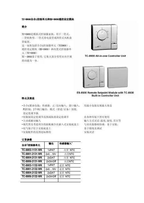
TC-8900全合1控制单元和ES-8930遥控设定模块简介TC-8900是模拟式控制器家族,用于二管式,二管转换型,二管式带电盘管或四管式风机盘管装置。
这一家族包括全合1控制器单元(TC8900)、遥控设定模块(ES-8930)和内置式控制器单元(TC-8930)TC-8900易于使用,它集大部分常用室内空调的功能为一身。
特点及效益-全合1紧凑包装:传感器,正/反向输入,窗口输入, 用最小包装实现最大效益PI控制,2个阀门输出,模式(舒适/后备)按钮,设定值调节器.-有限制设定值调节范围或取消设定值调节 在各种环境下皆可使用-主动或被动输入 输入方式灵活:温度,湿度,差压等 -现代型及考虑周全的面板嵌合在插入式安装底盒上 与室内装修相协调,易于安装。
-电气端子位于安装底盒上 易于接线及调试-安装配件的范围是标准的 安装灵活订货参数输出传感器输入*全合1控制器单元TC-8903-1131-WK 1xPAT 内置 NTCTC-8901-2131-WK 2x0…10V 内置NTCTC-8904-2131-WK 2xDAT 内置 NTCTC-8906-2131-WK 2xOn/Off 内置NTCTC-8903-1132-WK 1xPAT 遥置 NTCTC-8901-2132-WK 2x0…10V 遥置 NTCTC-8904-2132-WK 2xDAT 遥置 NTCTC-8906-2132-WK 2xOn/Off 遥置 NTC设定范围:12~28度输出传感器输入全合1控制器单元TC-8903-1151-WK 1xPAT 内置NTCTC-8903-1152-WK 1xPAT 遥置 NTC设定范围:0~40度输出传感器输入全合1控制器单元TC-8903-1183-WK 1xPAT 遥置0 (10V)TC-8901-2183-WK 2x0…10V 遥置0 (10V)设定范围:0~100%*遥置传感器输入:见本文件最后一页“技术规格”输出传感器输入内置控制器单元TC-8933-1112-W 1xPAT 从 ESTC-8931-2112-W 2x0…10V 从 ESTC-8934-2112-W 2xDAT 从 ESTC-8936-2112-W 2xOn/Off 从 ES*设定范围:遥控,见ES-8900遥控设定模块输出传感器输入*ES-8930-3031-WK --内置 NTC*设定范围:12~28摄氏度附件附件(分开定购)定购号 说明TM-9100-8900 传感器盒的开启工具TM-9100-8901 拨盘停止螺钉组(100只一包装的自攻螺钉)TM-9100-8931-W 塑料表面安装组件TM-9100-8941-W 墙装组件TM-9100-8951-W 面板安装组件附件详情见“RS-9100”产品手册技术特点-带NTC传感器输入的模块型号TC-8901 系列TC-8903 系列TC-8904 系列TC-8906 系列无控制作用带0 to 2 K - 0 to 2 K 0 to 2 K 差额- - - 0.2 to 2 K比例带1…4 K 2…8 K 1…4 K -分钟- 时间- 120 秒 5 (15)积分时间- 关闭或 4 分钟- - 备用偏差 BSB 2 K 2 K 2 K 2 K窗口偏差 BOF 5 K 5 K 5 K 5 K技术特点-带0-10V传感器输入的模块型号TC-8901-2183-WK TC-8903-1183-WK无控制作用带0 to 10% -比例带 5 to 20% 10 to 40%积分时间- 关闭或 4 分钟备用偏差 BSB 10% 10%窗口偏差 BOF 25% 25%应用TC-89x0控制器既可安装在墙上也可安装于风扇盘管之中,接收从遥置设定模块所发出的设定信息。
类型不同的温度控制仪有什么区别简介温度控制仪主要用于控制温度,利用控制器的输出信号,调整加热、制冷等设备的状态,从而维持设备的稳定温度。
不同类型的温度控制仪在原理、使用场景、控制精度等方面不同,本文将着重探讨这些方面的差异。
原理数字式温度控制仪数字式温度控制仪以数字电路为核心,可以实现计算、存储、控制等多项功能。
其主要原理就是通过控制传感器的采集,将温度信号转换为数字信号,再通过控制输出的方式,控制温度。
模拟式温度控制仪模拟式温度控制仪基于模拟电路,使用模拟信号来控制温度。
模拟式温度控制仪对于输入信号和控制信号的电压要求较高,且使用寿命短,逐渐被数字式温度控制仪所取代。
使用场景数字式温度控制仪数字式温度控制仪广泛应用于各种工业、农业、生活等领域。
数字式温度控制仪的特点是易于调节,响应速度快,精度高,稳定性好。
适合在恶劣的环境下使用,并且能够实现多项智能功能。
模拟式温度控制仪模拟式温度控制仪使用寿命短,通常只适用于小范围的温度控制,例如实验室的小型设备。
对于精度要求较低,使用环境较为温和的场合下,选择模拟式温度控制仪也是一种不错的选择。
控制精度数字式温度控制仪数字式温度控制仪具有高精度、高稳定性的特点。
数字式温度控制仪通过数字处理电路的精细控制,能够在更大的范围内实现对温度的控制和调节。
数字温度控制仪的精度通常在±0.2℃,甚至更高。
另外,数字式温度控制仪还具有抗干扰能力强,不易受周围环境的影响等优点。
模拟式温度控制仪模拟式温度控制仪控制精度一般较低,通常精度可达±1-2℃。
模拟式温度控制仪的调节灵敏度较低,不如数字式温度控制仪容易受到外界环境影响。
但是,由于其使用的电路较为简单,通常价格相对数字式温度控制仪较为便宜。
结论不同类型的温度控制仪在原理、使用场景、控制精度等方面各有不同。
由于数字式温度控制仪具有高精度、高稳定性等优点,目前已经成为主流的温度控制仪。
而模拟式温度控制仪则逐渐退出市场。
模拟光源控制器版本:V1.1编制日期:2018-9-20安全须知1、在第一次安装和使用本产品之前,请您务必先仔细阅读本使用说明书2、使用本产品之前,请确认输出规格(功率,电压,电流,端子定义)是否与所用LED光源的规格匹配3、请确保输入交流电源的地线可靠接地,已避免可能导致的财产损失或人身伤害。
4、连接光源线缆时务必断开输入电源。
通电前请仔细检查输入输出线缆是否连接正确,确保本产品可靠工作。
5、请勿在易燃易爆的环境下操作,请保持产品表面的清洁和干燥。
6、如果发现以下任何一种情况,或者对产品的安全有所顾虑,应停止使用本产品并断开与电源及其他线缆的连接,以降低造成人身伤害和财产损失的风险。
并请及时向供应商获取技术支持和售后服务。
6.1、电源线、电源插座、接线端子、开关按键等损坏;6.2、有烟雾,火花,或起火现象;6.3、产品发出异味或爆裂声;6.4、产品内部进水;6.5、按照使用说明书操作时产品不能正常工作。
7、除非得到本公司的许可和技术支持,否则请勿尝试自行维修产品。
模拟光源控制器操作说明书一、产品介绍KZQ-2424-2M/4M是模拟型控制器。
可通过手动旋钮无级调节控制光源产品光照度,两通道/四通道光源电压输出接口,应用于输出电压为24V,电流为1A/3A 以内的视觉光源上。
该产品具有高稳定性,快速触发响应,亮度无级调节,使用简单等优点,更大程度上节约安装空间和成本的优势。
二、产品型号三、功能参数四、接口说明4.1、两路模拟控制器面板示意图4.2、4路模拟控制器面板示意图4.3、面板接口说明五、连接步骤Step 1:将光源调节旋钮逆时针旋转到最小。
Step 2:将光源与控制器的光源电压输出接口连接。
Step 3:如果需要进行外部触发控制,请将外部触发信号源与控制器触发端口连接好。
Step 4:接入 AC 电源。
把红色电源开关按钮“-”按下,“O”突起, 指示灯亮,表示已上电。
Step 5:旋转调节旋钮使对应通道光源亮度达到需要值。
控制仪表课后答案第1-2-3章部分控制仪表课后答案第1-2-3章部分.,控制仪表及装置课后答案,控制仪表及装置第四版课后答案,控制仪表和装置课后答案,控制仪表与计算机控制课后题答案,控制仪表与计算机控制装置课后答案,控制仪表及装置课后答案吴勤勤,过程控制与仪表课后答案潘永湘,答案家,控制仪表及装置第四版思考与练习题参考答案第1章模拟式控制器思考与练习题(1)工业上常用控制器的控制规律有哪几种?答:工程上常用的控制器的控制规律有比例(P)、比例积分(PI)、比例微分(PD)以及比例积分微分(PID)四种,由此产生相应的四种常用控制器。
(2)在模拟控制器中,一般采用什方式实现各种控制规律?答:可以用负反馈放大器来实现。
其原理组成如图3.1所示。
=KUε控制仪表课后答案第1-2-3章部分.,控制仪表及装置课后答案,控制仪表及装置第四版课后答案,控制仪表和装置课后答案,控制仪表与计算机控制课后题答案,控制仪表与计算机控制装置课后答案,控制仪表及装置课后答案吴勤勤,过程控制与仪表课后答案潘永湘,答案家,控制仪表及装置第四版FUUf=O根据上述三个关系式可求得输出与输入的关系为:FKKUUi+=10当放大器的放大倍数足够大时,FK>>1,则上式分母中的1可忽略不计,上式可近似表示为:'01KFUUi=≈这就是说,只要放大器的放大倍数足够大,那么在引入负反馈构成闭环后,其闭环放大倍数K′就只与反馈系数F有关。
而反馈系数就是前面分析的分压系数,这样就实现了比例控制规律。
由于闭环放大倍数K′与反馈系数F成倒数关系,即后者衰减,前者放大,或者是,后者为除的关系,则前者就是乘的关系。
换句话说,两者之间互成逆运算关系。
由此得到了启发,若要闭环放大器起积分运算作用,它的反馈电路应是微分运算电路。
反之,要得到微分运算关系的放大电路,其反馈电路应该用积分电路。
(3)试述DDZ—Ⅲ型控制器的功能。
答:DDZ—Ⅲ型控制器的作用是将变器送来的1~5VDC测量信号与1~5VDC给定信号进行比较得到偏差信号,然后再将其偏差信号进行PID运算,输出4~20mADC信号,最后通过执行器,实现对过程参数的自动控制。