SMC电磁阀VP3145-061DLA1外形尺寸
- 格式:doc
- 大小:475.30 KB
- 文档页数:1

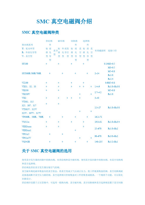
SMC电磁阀选型样本引言电磁阀作为自动化控制系统中常用的执行元件,广泛应用于工业生产中。
SMC 公司是世界上知名的气动控制和自动化设备制造商。
本文将介绍SMC电磁阀的选型要点,并给出一个选型样本。
选型要点在选择SMC电磁阀时,需要考虑以下几个要点:1. 工作压力工作压力是选型电磁阀的重要参数之一。
根据实际应用需要,选择适当的工作压力范围。
SMC电磁阀的工作压力通常在0.15MPa至1.0MPa之间。
2. 电压类型SMC电磁阀有直流和交流两种电压类型可选。
根据实际输入电压类型选择合适的电磁阀。
常见的电压类型有DC24V、AC110V和AC220V等。
3. 连接口径连接口径取决于系统的气源管道大小。
常见的连接口径有M5、G1/8、G1/4和G3/8等。
根据气源管道的尺寸选择合适的连接口径。
4. 工作模式根据实际工作需求,选择合适的工作模式。
SMC电磁阀常见的工作模式包括常闭型(通电时阀门关闭)和常开型(通电时阀门打开)。
5. 阀门类型SMC电磁阀有多种不同类型的阀门,包括直动式和间接式。
根据实际需求选择适合的阀门类型。
选型样本基于上述选型要点,以下是一个选型样本:标题:SMC电磁阀选型样本应用场景该选型样本适用于一个工业生产线上的气动控制系统,需要使用电磁阀控制气体流动。
选型要点•工作压力范围:0.15MPa至1.0MPa•电压类型:DC24V•连接口径:G1/4•工作模式:常开型•阀门类型:直动式选型结果基于以上要点,推荐选择以下型号的SMC电磁阀:型号:NVJ114-5G40B主要参数•工作压力范围:0.15MPa至1.0MPa•电压类型:DC24V•连接口径:G1/4•工作模式:常开型•阀门类型:直动式特点和优势•结构紧凑,体积小,重量轻•高性能密封材料,工作可靠•适用于空气、水和其他非腐蚀性介质的控制结论根据应用场景和选型要点,推荐选择SMC型号NVJ114-5G40B直动式常开型电磁阀,该电磁阀具有良好的工作压力范围、适合的接口尺寸和工作电压,并且具有紧凑的结构和高性能密封材料,能够满足工业生产线上的气动控制需求。

SMC电磁阀选型手册1. 引言本手册旨在为用户提供有关SMC电磁阀的选型指南。
电磁阀是一种广泛应用于自动化控制领域的关键元件,可在流体管路中控制液体或气体的流动。
SMC是一家全球领先的自动化控制解决方案提供商,其电磁阀系列以其高质量、可靠性和创新性而闻名。
本手册将介绍SMC电磁阀的工作原理、类型、特点、选型准则和常见问题。
通过阅读本手册,用户将能够了解如何选择适合其应用需求的SMC电磁阀,并能够正确使用和维护这些设备。
2. SMC电磁阀的工作原理SMC电磁阀是通过电磁力来控制流体管路中液体或气体的流动。
其工作原理基于电磁感应,当通电时,电流通过线圈产生磁场,通过磁场的作用,改变了阀体内的活塞位置,从而打开或关闭阀门。
SMC电磁阀通常由电磁线圈、阀体和活塞组成。
电磁线圈是产生磁场的关键部件,其通过通电来改变阀门的状态。
阀体是容纳活塞和阀门的部件,通过活塞的位置改变来改变阀门的状态。
活塞是负责控制阀门开闭的部件,具有很高的密封性和稳定性。
3. SMC电磁阀的类型SMC电磁阀按照用途可分为多种类型,下面将介绍一些常见的SMC电磁阀类型:3.1 直动式电磁阀直动式电磁阀是最常见的一种电磁阀类型,其工作原理和上述介绍的工作原理相同。
直动式电磁阀的特点是结构简单、尺寸小巧、反应速度快、可靠性高,适用于大多数普通应用场合。
3.2 比例式电磁阀比例式电磁阀是一种根据输入信号控制流量的电磁阀。
它具有流量调节范围广、精度高、稳定性好的特点,适用于需要精确控制流量的应用场合,如流量控制。
3.3 高频电磁阀高频电磁阀主要用于高频振动设备中,具有快速响应、高频率、低功耗、高效能的特点。
它通常用于需要频繁开关的场合,如高频研磨、高频冲击等。
3.4 单向电磁阀单向电磁阀是一种用于控制流体的单向流动的电磁阀,其特点是结构简单、操作方便、可靠性高。
它通常用于需要限制流体流向的场合。
4. SMC电磁阀的选型准则选择适合的SMC电磁阀是确保系统运行正常的关键之一。


Instruction ManualElectric Actuator / Rod Type Series LEYGMotor: AC servo motor (100-200 VAC)The intended use of thisElectrical Actuator is to convert an electrical input signal into mechanical motion.1 Safety InstructionsThese safety instructions are intended to prevent hazardous situations and/or equipment damage. These instructions indicate the level of potential hazard with the labels of “Caution,” “Warning” or “Danger.” They are all important notes for safety and must be followed in addition to International Standards (ISO/IEC) *1), and other safety regulations. *1)ISO 4414: Pneumatic fluid power - General rules relating to systems. ISO 4413: Hydraulic fluid power - General rules relating to systems.IEC 60204-1: Safety of machinery - Electrical equipment of machines. (Part 1: General requirements)ISO 10218-1: Manipulating industrial robots -Safety. etc.∙ Refer to the product catalogue, Operation Manual and Handling Precautions for SMC Products for additional information. ∙ Keep this manual in a safe place for future reference.CautionCaution indicates a hazard with a low level of risk which, ifnot avoided, could result in minor or moderate injury.WarningWarning indicates a hazard with a medium level of riskwhich, if not avoided, could result in death or serious injury.DangerDanger indicates a hazard with a high level of risk which, ifnot avoided, will result in death or serious injury.Warning∙ Always ensure compliance with relevant safety laws and standards.All work must be carried out in a safe manner by a qualified person in compliance with applicable national regulations.2 SpecificationsSeries LEYG - Motor: Step [servo 24 VDC]Product Weight [kg]30501001502002503003050100150200250300Incremental E ncoder[S2] 1.80 1.99 2.31 2.73 3.07 3.41 3.67 1.81 2.02 2.26 2.69 2.95 3.27 3.51AbsoluteE ncoder[S6] 1.86 2.05 2.37 2.79 3.13 3.47 3.73 1.87 2.08 2.32 2.75 3.01 3.33 3.57AbsoluteE ncoder[T6] 1.80 2.00 2.40 2.80 3.10 3.50 3.70 1.90 2.10 2.30 2.70 3.00 3.30 3.60Absolute E ncoder[V6]1.701.902.202.603.003.303.601.701.902.202.602.903.203.4030501001502002503003050100150200250300Incremental E ncoder[S2] 3.24 3.50 4.05 4.80 5.35 5.83 6.28 3.24 3.51 3.90 4.64 5.06 5.56 5.96AbsoluteE ncoder[S6] 3.18 3.44 3.99 4.74 5.29 5.77 6.22 3.18 3.45 3.84 4.58 5.00 5.50 5.90AbsoluteE ncoder[T6] 3.20 3.40 4.00 4.70 5.30 5.70 6.20 3.20 3.40 3.80 4.60 5.00 5.50 5.90Absolute E ncoder[V6]3.103.404.004.705.305.706.203.103.403.804.505.005.505.90In-line Motor Type30501001502002503003050100150200250300IncrementalE ncoder[S2] 1.83 2.02 2.34 2.76 3.10 3.44 3.70 1.84 2.05 2.29 2.72 2.98 3.30 3.54AbsoluteE ncoder[S6] 1.89 2.08 2.40 2.82 3.16 3.50 3.76 1.90 2.11 2.35 2.78 3.04 3.36 3.60AbsoluteE ncoder[T6] 1.90 2.10 2.40 2.80 3.10 3.50 3.70 1.90 2.10 2.30 2.80 3.00 3.30 3.60Absolute E ncoder[V6]1.701.902.202.603.003.303.601.702.002.202.602.903.203.4030501001502002503003050100150200250300Incremental E ncoder[S2] 3.26 3.52 4.07 4.82 5.37 5.85 6.30 3.26 3.53 3.92 4.66 5.08 5.58 5.98AbsoluteE ncoder[S6] 3.20 3.46 4.01 4.76 5.31 5.79 6.24 3.20 3.47 3.86 4.60 5.02 5.52 5.92AbsoluteE ncoder[T6] 3.20 3.40 4.00 4.70 5.30 5.80 6.20 3.20 3.40 3.80 4.60 5.00 5.50 5.90Absolute E ncoder[V6]3.203.404.004.705.305.806.203.203.403.804.605.005.505.90Stroke[mm] TypeofMotorLEYG32M LEYG32L Stroke[mm] TypeofMotorSeriesSeriesLEYG25M LEYG25L LEYG25M LEYG25L Stroke[mm] SeriesLEYG32M LEYG32L Stroke[mm] TypeofMotorTypeofMotorSeries2 Specifications (continued)A dditional Weight2532Incremental E ncoder[S2]0.200.40Absolute E ncoder[S6]0.300.66Absolute E ncoder[T6]0.300.70Absolute E ncoder[V6]0.300.60Size LockNote 1) Please consult with SMC for non-standard strokes produced tospecial order.Note 2) This is the maximum value of the horizontal work load. Anexternal guide is necessary to support the load. The actual work load changes according to the condition of the external guide. Confirm the load using the actual device.Note 3) Thrust setting range when "pushing" operation in torque controlmode, etc. Refer to the thrust conversion graph shown in the catalogue as a guide.Set value LEYG25#S/32#S: 15 to 30% Set value LEYG25#T/32#T: 12 to 24% Set value LEYG25#V/32#V: 45 to 90%Note 4) The allowable speed changes according to the stroke.Note 5) The allowable collision speed for collision with the workpiecewith the torque control mode.Note 6) A reference value for correcting an error in reciprocal operation. Note 7) Impact resistance: No malfunction occurred when the actuatorwas tested with a drop tester in both an axial direction and perpendicular direction to the lead screw (the test was performed with the actuator in the initial state).Vibration resistance:No malfunction occurred in a test ranging between 45 to 2000 Hz, when the actuator was tested in both an axial direction and a perpendicular direction to the lead screw (the test was performed with the actuator in the initial state).Note 8) When the motor type is "T6-T9",the resolution will changedepending on the driver type.Note 9) The maximum instantaneous power consumption (including thedriver) is for when the actuator is operating.Note 10) Only when the motor option, "with lock", is selected.Note 11) For an actuator with lock, add the power consumption for thelock.WarningFor special products which include a suffix of “-X#”, “-D#”, please refer to the customer drawing of that specific product.3 Installation3.1 InstallationWarning∙ Do not install the product unless the safety instructions have been read and understood.∙ Do not use the product in excess of its allowable specification as listed in Section 2.∙ Ensure the product is sized correctly and is suitable for the application. ∙ Do not operate the product by fixing the piston rod and moving the actuator body.∙ When installing, inspecting or performing maintenance on the product, be sure to turn off the power supplies. Then, lock it so it cannot be tampered with while work is happening.3.2 EnvironmentWarning∙ Do not use in an environment where corrosive gases, chemicals, salt water or steam are present.∙ Do not use in an explosive atmosphere.∙ Do not expose to direct sunlight. Use a suitable protective cover.∙ Do not install in a location subject to vibration or impact in excess of the product’s specifications .∙ Do not mount in a location exposed to radiant heat that would result in temperatures in excess of the product’s specifications. ∙ Prevent foreign particles from entering the product.3 Installation (continued)3.3 MountingWarning∙ Observe the required tightening torque for screws.Unless stated otherwise, tighten the screws to the recommended torque for mounting the product.∙ Do not make any alterations to the product.Alterations made to this product may lead to a loss of durability and damage to the product, which can lead to injury and damage to other equipment and machinery.Do not scratch or dent the sliding parts of the table or mounting face etc., by striking or holding them with other objects. The components are manufactured to precise tolerances, so that even a slight deformation may cause faulty operation or seizure.∙ Do not use the product until it has been verified that the equipment can be operated correctly.After mounting or repair, connect the power supply to the product and perform appropriate functional inspections to check it is mounted correctly.∙ Do not use the product until it has been verified that the equipment can be operated correctly.∙ After mounting or repair, connect the power supply to the product and perform appropriate functional inspections to check it is mounted correctly.∙ Allow sufficient space for maintenance and inspection.Caution∙ When mounting the product, use screws with adequate length and tighten them to the recommended torque.Tightening with larger torque than the specified range may cause mal-function while the tightening with smaller torque can allow the displacement of actuator position. In extreme conditions the actuator could become detached from it’s mounting position.Work fixed / Plate tapped typeTighten the product mounting screws to the specified torque.Tightening to a torque over the specified range can cause operation failure, and insufficient torque can cause displacing or dropping of the attachment.Body fixed / Top mountingBody fixed / Bottom mounting Mounting / Head side tapped styleModel Screw Max.tighteningtorque [Nm]Max. thread depth [mm] LEYG25 M5 x 0.8 3.0 12LEYG32 M6 x 1.0 5.2 12 Model Screw Max.tighteningtorque [Nm]Max. thread depth [mm] LEYG25 M5 x 0.8 3.0 40.3LEYG32 M6 x 1.0 5.2 50.3ORIGINAL INSTRUCTIONSModelLEYG25 LEYG25D (Parallel/In-line )LEYG32 (Parallel type) LEYG32D (In-line type) A c t u a t o r Stroke [mm] Note1)30, 50, 100, 150, 200, 250,300 30, 50, 100, 150, 200, 250,300 30, 50, 100, 150,200, 250,300 Work load [kg] HorizontalNote 2)18 50 50 30 60 60 30 60 60 Vertical 7 15 29 7 17 35 10 22 44Pushing force [N] Note3)65 to 131 127 to 255 242 to 485 79 to 157 154 to 308 294 to 588 98 to 197 192 to 385 368 to 736Maximum Speed[mm/s]Note4)900 450 225 1200 600 300 1000 500 250 Pushing Speed [mm/s]Note5)35 or less 30 or less Acceleration / Deceleration [mm/s 2] 5000 Positioningrepeatability [mm] Basic type ±0.02 Highprecision ±0.01Lost motion [mm] Note6) Basic type 0.1 or lessHigh precision 0.05 or lessLead [mm](including pulley ratio)12 6 3 20 10 5 16 8 4 Impact resistance/vibrationResistance [m/s 2] Note7)50 / 20 Actuation type Ball screw and Belt [1:1] / Ball screw Ball screw and Belt[1.25:1] Ball screwGuide typeSliding bearing (LEYG#M), Ball bush bearing (LEYG#L) Operating temperature range [℃] 5 to 40 Operating humidity range [%RH] 90 or less(No condensation) Regenerative optionMay be required by speed and work load(Refer to catalogue)E l e c t r i c a l Motor output/size 100W /☐40 200W /☐60 Type of MotorAC servo motor (100 / 200 VAC) Encoder Note8) Motor type S2-S3:Incremntal 17-bit encoder(Resolution:131072 p/rev)Motor type S6-S7:Absolute 18-bit encoder (Resolution:262144 p/rev)Motor type T6-T7:Absolute 22-bit encoder(Resolution:4194304 p/rev) Motor type V6-V7:Absolute 20-bit encoder (Resolution:1048576 p/rev) Maximum instantaneous power consumption [W] Note9) 445 724 L o c k u n i tType Note10) Non magneting lock Holding force [N] 131 255 485 157 308 588 197 385 736 Power consumption [W] at 20 ℃ Note11) LEY*G(S/T)* /LEY*G V * 6.3 / 5.5 7.9 / 6 Rated voltage[V] 24 VDC 0-10% Model Screw Max.tighteningtorque [Nm]Max. thread depth [mm] LEYG25 M5 x 0.8 3.0 8 LEYG32 M6 x 1.0 5.2 10Model Screw Max.tighteningtorque [Nm] Max. thread length [mm]LEYG25 M6 x 1.05.2 11 LEYG32 M6 x 1.0 5.2 123 Installation (continued)3.4 LubricationCaution∙SMC products have been lubricated for life at manufacture, and do notrequire lubrication in service.∙If a lubricant is used in the system, refer to catalogue for details.∙The recommended grease is lithium grade No.2Applied Region Grease Pack Number Weight [g]Piston rodGuideGR-S-010 10GR-S-020 20∙For products which include a “25A-” prefix the recommended grease islow condensation grease.Applied Region Grease Pack Number Weight [g]Piston rodGuideGR-D-010 104 Wiring4.1 WiringWarning∙Adjustment, mounting or wiring changes should not be carried outbefore disconnecting the power supply to the product.Electric shock, malfunction and damage can result.∙Do not disassemble the cables.∙Use only specified cables.Use only specified cables otherwise there may be risk of fire anddamage.∙Do not connect or disconnect the wires, cables and connectors whenthe power is turned on.Caution∙Wire the connector correctly and securely.Check the connector for polarity and do not apply any voltage to theterminals other than those specified in the Operation Manual.∙Take appropriate measures against noise.Noise in a signal line may cause malfunction. As a countermeasureseparate the high voltage and low voltage cables, and shorten thewiring lengths, etc.∙Do not route input/output wires and cables together with power or highvoltage cables.The product can malfunction due to noise interference and surgevoltage from power and high voltage cables close to the signal line.Route the wires of the product separately from power or high voltagecables.∙Take care that actuator movement does not catch cables.∙Operate with all wires and cables secured.∙Avoid bending cables at sharp angles where they enter the product.∙Avoid twisting, folding, rotating or applying an external force to thecable.Risk of electric shock, wire breakage, contact failure and loss of controlof the product can result.∙Select “Robotic cables”in applications where cables are movingrepeatedly (encoder/ motor/ lock).Refer to the relevant operation manual for the bending life of the cable.∙Confirm correct insulation.Poor insulation of wires, cables, connectors, terminals etc. can causeinterference with other circuits. Also there is the possibility thatexcessive voltage or current may be applied to the product causingdamage.∙R efer to the auto switch references in “Best Pneumatics“ when an autoswitch is to be used4.2 Actuator Ground connectionCaution∙The Actuator must be connected to ground to shield the actuator fromelectrical noise. The screw and cable with crimping terminal andtoothed washer should be prepared separately by the user.4 Wiring (continued)4.3 Wiring of Actuator to ControllerAC servo motor driverWarningUse only specified cables otherwise there may be risk of fire and damage5 How to Order∙For standard products, refer to the catalogue on the SMC website(URL: https://) for the how to order information.6 Outline Dimensions∙For standard products, refer to the catalogue on the SMC website(URL: https://) for outline dimensions.7 Maintenance7.1 General MaintenanceCaution∙Not following proper maintenance procedures could cause the productto malfunction and lead to equipment damage.∙If handled improperly electricity and compressed air can be dangerous.∙Maintenance of electromechanical and pneumatic systems should beperformed only by qualified personnel.∙Before performing maintenance, turn off the power supply and be sureto cut off the supply pressure. Confirm that the power has beendischarged and the air is released to atmosphere.∙After installation and maintenance, apply operating pressure andpower to the equipment and perform appropriate functional andleakage tests to make sure the equipment is installed correctly.∙If any electrical or pneumatic connections are disturbed duringmaintenance, ensure they are reconnected correctly and safety checksare carried out as required to ensure continued compliance withapplicable national regulations.∙Do not make any modification to the product.∙Do not disassemble the product, unless required by installation ormaintenance instructions.∙Incorrect handling can cause an injury, damage or malfunction of theequipment and machinery, so ensure that the procedure for the task isfollowed.∙Always allow sufficient space around the product to complete anymaintenance and inspection.7 Maintenance (continued)7.2 Periodical Maintenance∙Maintenance should be performed according to the table below:AppearanceCheckBelt CheckInspection before daily operation ✓Inspection every six months* ✓✓Inspection every 1,000 km* ✓✓Inspection every 5 million cycles* ✓✓*whichever of these occurs first.∙Following any maintenance, always perform a system check. Do notuse the product if any error occurs, as safety cannot be assured ifcaused by any un-intentional malfunction.7.3 Appearance Check∙The following items should be visually monitored to ensure that theactuator remains in good condition and there are no concerns flagged;・Loose Screws,・Abnormal level of dust or dirt,・Visual flaws / faults,・Cable connections,・Abnormal noises or vibrations.7.4 Belt Check∙If one of the 6 conditions below are seen, do not continue operatingthe actuator, contact SMC immediately.・Tooth shaped canvas is worn out.Canvas fibre becomes “fuzzy”, rubber is removed, and the fibre gainsa white colour. The lines of fibre become very unclear.・Peeling off or wearing of the side of the belt.The corner of the belt becomes round and frayed, with threadsbeginning to stick out.・Belt is partially cut.Belt is partially cut. Foreign matter could be caught in the teeth andcause flaws.・Vertical line of belt teeth.Flaw which is made when the belt runs on the flange.・Rubber back of the belt is softened and sticky.・Crack on the back of the belt.8 Limitations of Use8.1 Limited warranty and disclaimer/compliance requirements∙Refer to Handling Precautions for SMC Products.9 Product disposalThis product should not be disposed of as municipal waste. Check yourlocal regulations and guidelines to dispose of this product correctly, inorder to reduce the impact on human health and the environment.10 ContactsRefer to or www.smc.eu for your local distributor /importer.URL : http// (Global) http// (Europe)'SMC Corporation, 4-14-1, Sotokanda, Chiyoda-ku, Tokyo 101-0021, JapanSpecifications are subject to change without prior notice from the manufacturer.© 2021 SMC Corporation All Rights Reserved.Template DKP50047-F-085M24VDC(5) Lock cable(4) Encoder cable(3) Motor cable(1) Electric Actuator(2) DriverHostcontroller,etc(6) I/O Connector。
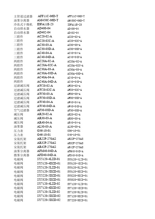
主管道过滤器 AFF11C-06D-T AFF11C-06D-T 油雾分离器AM450C-06D-T AM450C-06D-T 冷冻式干燥机IDFA11E-23IDFA11E-23自动排水器AD400-04AD400-04自动排水器AD402-04AD402-04三联件AC20-02-A AC20-02-A三联件AC20-02C-A AC20-02C-A三联件AC30-03-A AC30-03-A三联件AC30-03D-A AC30-03D-A三联件AC40-04-A AC40-04-A三联件AC40-04D-A AC40-04D-A两联件AC20A-02-A AC20A-02-A两联件AC20A-02C-A AC20A-02C-A两联件AC30A-03-A AC30A-03-A两联件AC30A-03D-A AC30A-03D-A两联件AC40A-04-A AC40-04-A两联件AC40A-04D-A AC40-04D-A过滤减压阀AW20-02-A AW20-02-A过滤减压阀AW20-02C-A AW20-02C-A过滤减压阀AW30-03-A AW30-03-A过滤减压阀AW30-03D-A AW30-03D-A过滤减压阀AW40-04-A AW40-04-A过滤减压阀AW40-04D-A AW40-04D-A空气过滤器AF30-03D-A AF30-03D-A减压阀AR20-02-A AR20-02-A减压阀AR30-03-A AR30-03-A减压阀AR40-04-A AR40-04-A油雾器AL30-03-A AL30-03-A压力表G36-10-01G36-10-01压力表G46-10-01G46-10-01安装托架AR22P-270AS AR22P-270AS安装托架AR32P-270AS AR32P-270AS安装托架AR42P-270AS AR42P-270AS油雾分离器AFM40-04D-A AFM40-04D-A微雾分离器AFD40-04D-A AFD40-04D-A电磁阀SY5120-4LZD-01SY5120-4LZD-01电磁阀SY5120-4DZD-01SY5120-4DZD-01电磁阀SY5120-5LZD-01SY5120-5LZD-01电磁阀SY5120-5DZD-01SY5120-5DZD-01电磁阀SY5220-5DZD-01SY5220-5DZD-01电磁阀SY5320-5DZD-01SY5320-5DZD-01电磁阀SY7120-4LZD-02SY7120-4LZD-01电磁阀SY7120-4DZD-02SY7120-4DZD-01电磁阀SY7120-5LZD-02SY7120-5LZD-01电磁阀SY7120-5DZD-02SY7120-5DZD-01电磁阀SY7220-5DZD-02SY7220-5DZD-01电磁阀SY7320-5DZD-02SY7320-5DZD-01电磁阀SY9120-5DZD-03SY9120-5DZD-01电磁阀VFS1120-5DZB-01VFS1110-5DZD-01电磁阀VF3130-5DZB-02VFS2120-5DZD-02电磁阀VF5120-5DZB-03VF3130-5DZD-01电磁阀VFS4110-5DZB-04VF5110-5DZD-01消音器AN101-01AN101-01消音器AN10-01A10-01消音器AN20-02/AN30-03/AN40-04AN20-02/30-03/40-04排气节流阀ASN2-01/02/03/04ASN2-01/02/-03/-04单向节流阀AS1201F-M5-06A AS1101-M5-06A单向节流阀AS2201F-01-06SA AS1101-01-06AS单向节流阀AS2201F-02-06S AS2101-02-06A单向节流阀AS3201F-03-08S AS3101-03-08A单向节流阀AS4201F-04-10S AS4101-04-10A气管TU0604BU-20TU0604BU-20气管TU0805BU-20TU0805BU-20气管TU1065BU-20TU1065BU-20气管TU1208BU-20TU1208BU-20接头KQ2H06-01AS KQ2H06-01-A接头KQ2L08-02AS KQ2L08-02-A接头KQ2T04-00A KQ2T04-00-A接头KQ2U10-00A KQ2U10-00-A接头KQ2H12-00A KQ2H12-00-A变径接头KQ2R06-08A KQ2R06-08-A隔板接头KQ2E04-00A KQ2E04-00-A隔板接头KQ2E12-03A KQ2E12-03-APLU1/4PLU1/4口径3/4,自动排水,带滤芯闭塞指示器口径3/4,自动,带滤芯闭塞指示器适用11KW,环保冷媒,不锈钢热交换器,已带自动排水器,接管口径3/4口径1/2,自动排水,带手动开关口径1/2,自动排水口径1/4,手动排水,带托架Y200T两件,不带压力表口径1/4,自动排水,带托架Y200T两件,不带压力表口径3/8,手动排水,带托架Y300T两件,不带压力表口径3/8,自动排水,带托架Y300T两件,不带压力表口径1/2,手动排水,带托架Y400T两件,不带压力表口径1/2,自动排水,带托架Y400T两件,不带压力表口径1/4,手动排水,带托架Y200T一件,不带压力表口径1/4,自动排水,带托架Y200T一件,不带表口径3/8,手动排水,带托架Y300T一件,不带表口径3/8,自动排水,带托架Y300T一件,不代表口径1/2,手动排水,带托架Y400T一件,不带表口径1/2,自动排水,带托架Y400T一件,不带表口径1/4,手动排水,不带托架不带表口径1/4,自动排水,不带托架不带表口径3/8,手动排水,不带托架不带表口径3/8,自动排水,不带托架不带表口径1/2,手动排水,不带托架不带表口径1/2,自动排水,不带托架不带表口径3/8,自动排水,不带托架口径1/4,不带托架不带表口径3/8,不带托架不带表口径1/2,不带托架不带表口径3/8,不带托架口径1/8,适用AC/AW/AR---20,30系列口径1/8,适用AC/AW/AR---40系列适用AW/AR---20系列适用AW/AR---30系列适用AW/AR---40系列口径1/2,自动排水,不带托架口径1/2,自动排水,不带托架口径1/8,2位5通单电控AC220V,不带托架口径1/8,2位5通单电控AC220V,不带托架口径1/8,2位5通单电控DC24V,不带托架口径1/8,2位5通单电控DC24V,不带托架口径1/8,2位5通双电控DC24V,不带托架口径1/8,3位5通电磁阀DC24V,不带托架口径1/4,2位5通单电控AC220V,不带托架口径1/4,2位5通单电控AC220V,不带托架口径1/4,2位5通单电控DC24V,不带托架口径1/4,2位5通单电控DC24V,不带托架口径1/4,2位5通双电控DC24V,不带托架口径1/4,3位5通电磁阀DC24V,不带托架口径3/8,2位5通单电控DC24V口径1/8,2位5通单电控DC24V口径1/4,2位5通单电控DC24V口径3/8,2位5通单电控DC24V口径1/2,2位5通单电控DC24V口径1/8,烧结金属型口径1/8,树脂型口径对应1/4,3/8/,1/2,树脂型口径1/8,1/4,3/8,1/2口径M5,插管6口径1/8,插管6口径1/4,插管6口径3/8,插管8口径1/2,插管10PU气管,外径6,内径4,颜色蓝色,20米1卷PU气管,外径8,内径5,颜色蓝色,20米1卷PU气管,外径10,内径6.5,颜色蓝色,20米1卷PU气管,外径12,内径8,颜色蓝色,20米1卷插管6,螺纹1/8,直通型插管8,螺纹1/4,直角型T型三通插管4Y型三通插管10直通双边插管128接头变径6快插隔板两边插管4隔板一边插管12,一边内螺纹3/8堵头1/4。