无线温湿度记录仪说明书
- 格式:docx
- 大小:20.07 KB
- 文档页数:8
温湿度计操作说明书操作说明书一、产品概述:温湿度计是一种用于测量室内温度和湿度的便携式仪器。
它配备了高精度的温湿度传感器,并具有简洁易用的操作界面,适用于各种室内环境,如家庭、办公室、实验室等。
二、产品外观及配件:1. 温湿度计主机:外观小巧玲珑,携带方便。
2. 用户手册:提供详细的操作指南和维护说明。
三、功能描述:1. 温度测量:温湿度计能够准确测量室内温度,温度显示范围为-10℃至50℃。
2. 湿度测量:温湿度计能够准确测量室内湿度,湿度显示范围为20%RH至95%RH。
3. 温度和湿度历史记录:温湿度计能够记录最近的温度和湿度数据,并提供历史记录查询功能,方便用户了解室内环境的变化趋势。
4. 温度和湿度报警功能:温湿度计能够设定温度和湿度的上下限,并在超出设定范围时发出报警提示,提醒用户调整室内环境。
5. 温湿度单位切换:温湿度计支持摄氏度和华氏度、相对湿度和绝对湿度单位的切换。
6. 温湿度数据保存和导出:用户可以将温湿度计记录的数据通过USB接口导出到计算机进行保存和分析。
四、操作步骤:1. 开机:将温湿度计主机的电源开关拨至“ON”位置,仪器自动开启并显示当前的温度和湿度数据。
2. 温度和湿度测量:- 温度测量:温湿度计主机默认以摄氏度单位进行温度测量。
在屏幕上方的温度显示区域可以即时获取当前的温度数值。
- 湿度测量:温湿度计主机默认以相对湿度单位进行湿度测量。
在屏幕下方的湿度显示区域可以即时获取当前的湿度数值。
3. 历史记录查询:- 按下“历史记录”按钮,进入历史记录查询界面。
- 使用方向键选择日期,通过“确定”按钮确认选择。
- 温湿度计将显示所选日期内的历史温度和湿度数据。
4. 温湿度报警设置:- 按下“设置”按钮,进入设置界面。
- 使用方向键选择“温度报警”或“湿度报警”选项,通过“确定”按钮确认选择。
- 设置温度或湿度的上下限数值,并通过“确定”按钮保存设置。
- 当温度或湿度超过设定范围时,温湿度计将发出报警提示。

温湿度记录仪操作使用说明手册北京堃堃科技有限公司KSP_RTHN(4I)(4O)型温湿度记录仪操作使用说明手册1.产品简介KSP-RTHN(4I)(4O)型温湿度记录仪是我司基于新版《药品经营质量管理规范》(简称新版GSP规范),并结合研发温湿度监测系统多年来的行业经验,独立自主研发的一款完全适合新版GSP认证的温湿度记录仪。
2产品特征1性能优越,处理速度快。
基于ARM的STM32低功耗芯片,处理能力超强,远超传统单片机芯片。
1.精度高。
采用瑞士原装进口数字温湿度芯片,温湿度精度远高于国产芯片。
2.稳定性高。
从设计到生产层层严格把关。
3.美观大方,操作人性化。
3.应用场合KSP-RTHN(4I)(4O)型温湿度记录仪不仅可以完美应用于GSP认证,还可广泛用于疾控中心、家居、办公场所、酒店、餐厅、农业研究、食品、医药、化工、气象、环保、电子、实验室等领域。
4.综合参数1.尺寸与重量2.结构3.功能特性4.硬件及信号特性5.产品展示第一章显示整个屏幕划分为上部和下部,由一根黑色实线隔开,上部又划分为左部和右部。
屏幕上的各个细节的显示含义分别如下:一、上部:1.左部:从上向下每行依次为:1)用户标识编号(ID)。
用来指定不同的设备,因此在同一网络不允许出现两个相同标号的设备。
2)上级服务器类型。
此行共两个图标,同一时刻只能有一个图标被点亮。
左边图标被亮时,表示上级直连一级服务器(电脑),右边图标亮时表示直连的是二级服务器。
3)报警显示。
若此警铃图标被点亮说明有报警产生。
4)无线网络连接状态。
若选配GPRS设备连接则此图标会显示相应的网络强度。
2.右部:从上到下每行依次为:1)温度信息:此行的数值表示温度值,注意前面的H和L字母,在数值后面有温度单位,可以通过设置使设备在华氏和摄氏之间转换显示。
正常态:①显示实时温度值,并且字母H和L不会显示。
报警态:纯报警态(设备报警时用户操作使设备进入设定态,称为非纯报警态,此时警铃、报警音、报警灯仍然有效)时H和L不会同时被点亮。
RCW-800WIoT Data Logger ManualElitech iCold Platform: RCW-800W series is an IoT recorder that communicates through WIFI network, which is used for real-time monitoring, recording, alarming and data uploading of ambient tempera-ture/humidity. The recorder is mainly composed of a temperature/humidity sensor and a host instrument. It directly transmits the measured value to the Elitech cold cloud through the Wi-Fi network. It can be stored in the Elitech cold anytime, anywhere through mobile phones and PCs with Internet access functions. View and analyze the data in the cloud platform. After the limit is exceeded, the alarm can be sent in time through SMS, email, voice and other methods.*When the temperature and humidity are higher than the upper limit, the screen value will display red; when the temperature and humidity are lower than the lower limit, the screen value will display blue.● Small size, stylish shape, magnetic tray design, easy to install ● Large-size TFT color screen display● Built-in rechargeable lithium battery, can still provide real-time data upload for a longtime after power failure● The product is suitable for warehouses, cold storage, refrigerated trucks, cool cabinets, medicine cabinets, freezer laboratories and other scenarios①② Time ③ Date④ Probe 1⑤ Currenttemperature ⑥ Devicestatus⑦ Buzzer status ⑧ WIFI module status⑨ Battery power status⑩ Charging statu⑪ Probe 2⑫ Currenthumidity⑬ Number ofo ine data① Power LED Light ② Alarm LED Light③ LCD Display screen④ Home key ⑤ Right key⑥ Monitoring start/stop ⑦ Buzzer on/o⑦ Micro usb port③ Back cover screws⑤ Sensor port ⑥ Power switch④ Reset button(short press to enter thedistribution network, long press to restart t he device)⑩ Celsius/Fahrenheit conversion⑨ ② Batterycover① Bracket6. Instructions1. Power input: 5V/1A2. Temperature display resolution: 0.1℃3. Humidity display resolution: 0.1%RH4. O ine record :20,000 points5. Data storage method: circulating memory6. Record,Upload interval &Alarm interval① Normal Recording interval: 1min~24H can be set② Alarm logging interval:1min~24H can be set(The alarm recording interval must be less than or equal to the normal recording interval)③ Normal Upload interval: 1min~24H can be set,default5mins④ Alarm upload interval: 1min~24H can be set,default2mins(The alarm upload interval must be less than or equal to the normal upload interval)7.Battery life: no less than 7 days (@25℃, upload interval 5 minutes)8.Indicator light: Alarm indicator light, charging indicator light 9.Screen: TFT color screenmunication method: WIFI11.Alarm method:Local alarm, cloud alarm (SMS, APP , email)12.Buttons: switch machine, reset button (WIFI/Bluetooth), left key, home key, right key, Celsius/Fahrenheit conversion, monitoring start/stop, buzzer on/o ,13.Protection grade: IP5014.Standard sizes:110mm*78mm*27mm● ChargeConnect to the power adapter via a USB cable;When charging, the charging indicator light will be always on.The status bar will display the5. Technical Specifications● Interface●ButtonBuzzer on/off key: long press for 3 seconds, the buzzer function is turned on/closure open icon / close iconShort press in an alarm state will turn off the current buzzer alarmHome button: Short press to switch to the home page Left key: short press the interface to page forward Right key: short press the interface to page backwardsCelsius/Fahrenheit conversion key: press and hold for 3 seconds, the temperature unit will switch between Celsius/Fahrenheit.Monitoring start/stop button: long press for 3 seconds, start/stop monitoring, data start/stop record storage, displayThe lower left corner will display the status synchronously: monitoring/not monitoring① Probe 1temperature alarm limit ② Probe 2temperature alarm limit③ Temperature upper limit alarm value Dual temperature configuration parameter interfaceTemperature and humidity configuration parameter interface④ Temperature lower limit alarm value⑤ Temperature upper limit alarm value ⑥ Temperature lower limit alarm value① Probe 1temperature alarm limit ② Probe 1 humidity alarm limit③ Temperature upperlimit alarm value ④ Temperature lowerlimit alarm value ⑤ Humidity upper limit alarm value ⑥ Humidity lowerlimit alarm value2. Account registration and loginOpen the APP , in the login interface (as shown in Figure 1), enter the verification information according to the prompts, and click "Login" to complete the account login. If you have not yet registered an account, please click "Register Now" " in the login interface. In this interface (as shown in Figure 2), enter the verification information according to the prompts to complete the account registration.① Time interval between two data recordings ② Data logging interval when alarming ③ Data upload interval④ Time interval for uploading data to cloud platform when alarming⑤ Current record time of the collector ⑥ The total number of data recorded by the collector this timeIP addressWIFI MAC address ID number 20 digits Software versionWIFI configured: configured/unconfigured⑦ Automatic sleep time after no operation1.Download and install APPPlease scan the QR code below to download the "Elitech iCold"Configuration parameter interfacesystem information interface3.WiFi distribution network1)Connect the phone to the WiFi network and open the APP;2)Short press the reset button on the back of the machine to enter the WiFi network configuration mode, please see the LCD status bar icon for the specific status;Figure 1: Account login interface Figure 2: Account registration interface3) Follow the steps below to configure WiFi, the top of the screen displays " ", and the device has successfully configured WiFi;Open the APP,click the “ ” icon;Click the " " icon, scan the QR code on the back of the device or manually enter the device GUID;Edit the device name, select the time zone, and click "Add"to add the device successfully.4. Bluetooth distribution network1) Connect the phone to the WiFi network, open the APP and Bluetooth;2) Short press the reset button on the back of the machine to switch to the Bluetooth network configuration mode. Please see the LCD status bar icon for the specific status;Figure 3: Device InformationClick "Confirm" to start configuring WiFi;4) If the device WiFi configuration is unsuccessful, repeat the above steps 1) to 3).5) When the device needs to reconfigure WiFi, follow steps 1) to 2). Then open the "Device Information"⑤~⑥Enter the WiFi password in the APP;Click "Confirm", the WiFiconfiguration is successful.For more functions, please log in to the Elitech iCloud platform: , do more.After the device is added for the first time, you can get free SMS, data and premium service trial, please recharge the device after the trial service expires. For more recharge details, please refer to the "Elitech Cold Cloud Value-added Service Recharge Guide" in the APP to operate.3) Refer to the WiFi network for the network steps, and the Bluetooth network can support static IP address settings.④ Enter the WiFi password in the APP①Turn on the Bluetooth network②Obtain IP address automatically③Turn o automatic IP address acquisition: fill in the IP address manually Please refer to the current networking message requirements:IP address, subnet grab code, gateway address, DSN server address9.。
DM588网络型温湿度记录仪产品说明书功能简介●高精度、高稳定温湿度传感器●超大显示屏、带背光●体积小、重量轻、功耗低、反应速度快●具有记录功能、最大记录点数:12800●USB通信、485通信●9~36V(DC/AC)/USB 5V供电可选●内置报警功能、带报警输出●内置锂电池(可充电)一、产品概述DM588网络型温湿度记录仪是一款高性能工业级温湿度变送器,超大显示屏能实时显示温湿度数据,且带有背光功能,内置锂电池和报警器,具有报警控制输出功能,功能强大,适用范围极广。
该温湿度变送器具有体积小,重量轻、量程宽、精度高、且响应速度快和长期稳定性好等特点,使它广泛应用于楼宇自动化、气候与暖通信号采集、博物馆与宾馆的气候站、仓储物流以及医疗行业、机房温度监控等各种重要对空气中的温湿度进行测量和控制的领域。
二、产品参数1、供电电压:9~36VDC或USB 5V或内置锂电池2、显示分辨率:0.1℃或0.1%RH3、工作温度:-20~+60℃;精度:±0.3℃4、工作湿度:1~99.9%RH;精度:±2%RH5、采样周期:外电:2s 内置电池:5s6、记录点数:12800(最大)7、功耗:外电:<20mA 锂电池:<2mA8、灵敏度衰减值:温度<0.1℃;湿度<0.1%RH9、电池工作时间:充满电可以持续工作半年以上(不开报警及背光)10、输出信号:RS485信号11、通信协议:标准MODBUS RTU协议*配我公司温湿度监测软件V2.9三、产品尺寸(单位:mm )四、产品安装及接线说明◎该产品采用的安装方式1、将4芯(或带屏蔽)连接电缆变送器端的四根线分别连接到变送器连接头的1、2、3、4脚(带屏蔽线的屏蔽层连接到电源地);2、另一端对应接入供电电源和计算机(需485转换器)或其它相应设备;3、将变送器前后外壳扣紧;4、经检查接线无误后方可接通电源,检查变送器输出是否正常;5、现在变送器可以正常工作了;6、如需外接报警器请按485典型应用图来连接。
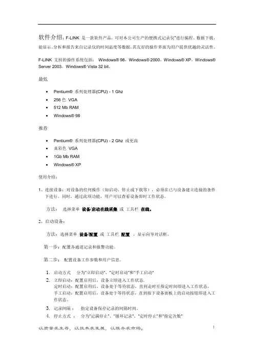
软件介绍:F-LINK 是一款软件产品,可对本公司生产的便携式记录仪”进行编程、数据下载,能显示、分析和报告来自记录仪的时间温度等数据,其友好的操作界面为用户提供优越的灵活性。
F-LINK 支持的操作系统包括:Windows® 98,Windows® 2000,Windows® XP,Windows® Server 2003,Windows® Vista 32 bit。
最低•Pentium® 系列处理器(CPU) - 1 Ghz•256色VGA•512 Mb RAM•Windows® 98推荐•Pentium® 系列处理器(CPU) - 2 Ghz 或更高•真彩色VGA•1Gb Mb RAM•Windows® XP使用介绍:1、连接设备:对设备的任何操作(如启动、停止或下载等),必须在已与设备建立连接的条件下进行。
同时,通过此项功能,用户可以查看设备即时工作状态。
方法:选择菜单设备/启动在线采集或工具栏在线。
2、启动设备:方法:选择菜单设备/配置或工具栏配置,显示向导对话框。
第一步:配置各通道记录和报警功能。
第二步:配置设备工作参数和用户信息。
1.启动方式分为"立即启动"、"定时启动"和"手工启动"2.立即启动:配置启用后,设备立即进入工作状态.定时启动:配置启用后,设备处于等待状态,直到走时至指定时间即进入工作状态。
手工启动:配置启用后,设备处于等待状态,直到按下设备面板上的启动按钮即进入工作状态。
3.记录间隔:指定设备保存记录的间隔时间。
4.停止方式:分为"记满停止"、"循环记录"、"定时停止"和"指定次数"记满停止: 当存储空间耗尽时,设备停止工作。
循环记录: 当存储空间耗尽时,以新记录覆盖旧记录,设备始终处于工作状态。
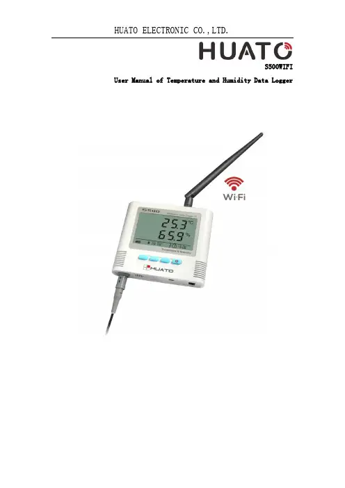
S500WIFI User Manual of Temperature and Humidity Data LoggerCONTENTSCHAPTER 1. INTRODUCTION (1)1.1F EATURES (1)1.2A PPLICATION (1)1.3S PECIFICATIONS (1)1.4S TRUCTURE I NSTRUCTION (2)1.5LCD D ISPLAY I NSTRUCTIONS (2)1.6I NSTRUCTION OF B UTTONS (4)CHAPTER 2. SOFTWARE (5)2.1WIFI S ETUP (5)2.2I NSTRUCTION OF T O M ONITOR SOFTWARE (9)2.3D ATA A NALYSIS (11)CHAPTER 3. FAQ (14)3.1LCD S CREEN D IM (14)3.2S OFTWARE "R UNTIME E RROR" (14)3.3C HECK COM P ORT N UMBER (14)Chapter 1. Introduction1.1 Features⏹Elegant appearance, easy to operate and reliable. Desktop and wall-mounted⏹Transferring real-time temperature and humidity data to computer throughWIFI⏹High accuracy: 0.2~0.5℃/2~5%RH⏹Large Capacity: 65000 data groups⏹Can be locked to display maximum and minimum value⏹Internal audible and visual alarm and send alarm message to mobile phoneonce temperature or humidity is over limit.⏹Multiple levels of data protection; all the collected data will not be lost.1.2Application⏹Widely used in environment with WIFI access to monitor temperatureand humidity.1.3Specifications1.4Structure Instruction1. LCD display2. ON/OFF3. Backlight4. MAX/MIN checking button5. LOG6. Hanger (used for fixing on the wall)7. Battery cover (screw to replace the battery)8. Holder (used for desktop)9.WIFI reset button1.5 LCD Display InstructionsBacklightAlarming for over limit of temperature or humidity TemperatureHumidityBattery indicationButtons locked/unlockedExternal AC 12V power connectedConnected to computer by USB cableLogger is in the logging modeNumber of data groups collectedMaximum value is displayedMinimum value is displayedTime1.6 Instruction of ButtonsChapter 2. Software2.1 WIFI SetupCopy the WIFIConfig software from the accompanied CD in the package to a computer, then to the designated cell phone(Android Cell Phone only). Install the software which will create icon.Reset the logger for 3-5 seconds(reset hole is at the upper corner in the back of logger),then search for network module of thisdevice(defaulted as RAK415-AP-606AB0) in WIFI settings of the cell phone and choose it.Open WIFICONFIG software in the cell phone, slide down the screen to refresh interface of the app, then click on RAK415WIFI to enter setting mode.2.1.1 Click on 【OK】button to confirm 【Certificate】.2.1.2 Click on【Mode】in the function list, then choose 【STA】 and 【Save】to save settings.Click on Save2.1.3 Click on【STA】 and choose the WIFI name and input password, then 【Save】to save the settings.Name of the WIFIconnectionWIFI Password2.1.4 Socket SettingsChoose TCP-ClientObject IPObject Port【Object IP】is the IP address of the computer where the data is stored,for example: 192.168.1.25;As of【Object Port】,please enter “4588”.2.1.5 Click on【Settings】,then 【RESET】to save settings and restart WIFI module of the logger.Click on RESET2.2 Instruction of ToMonitor software(1)Copy the software folder to the computer, then open the softwareDouble clickTomonitor(2) User Name: admin;Password: adminTo Login(3)Add New Logger in Tomonitor1.Run Tomonitor software & Login2.Press "Loggers”3.Choose a logger in the logger list and display its properties onthe right side4.Input the new logger's Serial Number & Name.Tips: Name cannot include symbol. SerialNumber is on the label of the logger5.Sampling (Seconds): When S500-GPRS upload real-time data,ToMonitor will sync this value to the data logger’s “LoggingInterval” (Logging/Upload frequency) property.6.Logger type choose 【Wireless】7.Press 【Add】 and 【Exit】to enter the monitoring interface8.In short time, real-time data collected by the logger will bedisplayed263 4572.3 Data Analysis(Notice:ToMonitor needs to be opened before we can use ToClient8 software which is used for data analysis)(1)Open Toclient8 software in the software folderClick ToClient8(2) Click on 【Connect】to login.【Password】is “admin”.(3)Data Query:(4)It will come out the following graph(5)Click on 【Data List 】to get historic dataChoose the loggerStart QueryTime SettingData ListChapter 3. FAQ3.1 LCD Screen DimReason:●Insufficient battery or the environment temperature is too low or toohigh.Solution:●In the case of insufficient battery, please replace the battery. Ifresulted from environment temperature, please immediately take the logger out of the environment.3.2 Software "Runtime Error"Reason:●OS forbid software creating files.Solution:●Run the program (software) as an administrator.●Install software in Disk D:\● A data logger name cannot contain any of the following characters:\ / : * ? " < > |●Software’s installation path cannot include Chinese character orgarbage character.3.3 Check COM Port Number●Press “Win” + “R” in keyboard -> Run "devmgmt.msc" to Open "DeviceManager" in Windows-> Expand "Ports (COM & LPT)" -> "USB-SERIAL CH340 (COM No.)" is the Data Logger。
Wireless Thermo-Hygro MonitorModel: WH0280Content1. Introduce (2)2. Get Started (2)2.1 Package Contents (2)2.2Recommend Tools (2)2.3 Thermometer Sensor Set Up (2)2.4 Display Console Set Up (4)3. Wireless Sensor Installation (6)3.1 Mounting with Zip Tie (7)4. Console Operation (7)4.1 Key function (7)4.2.Normal model (8)4.3 Time alarm model (9)4.4Min value model (9)4.5Max value model (10)4.6 Setting model (11)4.7. Setting model for alarm clock ................... 错误!未定义书签。
5.Sensor Resynchronization (10)6.Best Practices for Wireless Communication (10)7.Specifications (12)7.1.Wireless Specifications (12)7.2Measurement Specifications (12)7.3Power Consumption (12)8. Troubleshooting Guide (13)1. IntroduceThank you for your purchasing of this Wireless Indoor/Outdoor Thermometer with indoor humidity. To ensure the best product performance, please read this manual and retain it for future reference.2. Get StartedNote: The power up sequence must be performed in the order shown in this section: insert batteries in the remote sensor first, display console second.The weather station consists of a display console (receiver), and up to 3 thermometers (remote sensors), based on your order configuration.2.1 Package Contents2.2 Recommend ToolsHammer for hanging remote thermometer transmitter.2.3 Thermometer Sensor Set UpNote: Do not use rechargeable batteries. They tend to have a lower operating voltage, do not have a wide temperature range, and do not last as long as non-rechargeable batteries.We recommend fresh alkaline batteries for outdoor temperature ranges between -20°C and 60°C and fresh lithium batteries for outdoor temperature ranges between -40 °C and 60 °C.1.Remove the battery door on the back of the sensor by sliding thecompartment door down, as shown in Figure 1.2.Set RF sensor channel.Figure 13.Insert one AA battery in the back of the sensor4.After inserting the battery, the remote sensor LED indicator will lightfor 4 seconds, and then flash once per 60 seconds thereafter. Each time it flashes, the sensor is transmitting data.5.Close the battery door.2.4 Display Console Set Up1. Move the remote thermometer(s) about 2 to 3m away from thedisplay console (if the sensor is too close, it may not be received by the display console).2. Remove the battery door on the back of the display. Insert one AA(alkaline or lithium, avoid rechargeable) battery in the back of the display console.All of the LCD segments will light up for a few seconds to verify all segments are operating properly.Figure 23. Replace the battery door, and fold out the desk stand and placethe console in the upright position.The console will instantly display indoor temperature and humidity.The remote temperature will update on the display within a few minutes.While in the search mode, the reception search icon flash.Note: If the remote does not update, please reference the troubleshooting guide in Section.2.4.1 Display Console Layout2.4.2 Sensor Operation VerificationVerify the indoor and outdoor temperature match closely with the console and sensor array in the same location (about 2 to 3m apart). The sensors should be within 2°C (the accuracy is ±1°C. Allow about 30 minutes for both sensors to stabilize.3. Wireless Sensor InstallationIt is recommended you mount the remote sensor in a shaded area. Direct sunlight and radiant heat sources will result in inaccurate temperature readings. Although the sensor is water resistant, it is best to mount in a well-protected area, such as under an eve.3.1 Mounting with Zip TieMounting the sensor with a zip tie will result in better accuracy when mounting outside, since it is not touching other objects.Figure 43.2 Mounting with Nail or screwTo mount the sensor with a nail or screw, the cap must be less than or equal to 5mm in diameter.Figure 54. Console OperationThe console has two buttons at the back of console for easy operation. If no operation for 30s, display will return back to normal mode.There are five program modes available: Setting mode, Time Alarm Mode, MIN/MAX Mode, Loop display Mode and Sensor Register Mode4.1 Setting ModeWhile in normal display, press the MODE key for 2 seconds to enter Setting ModePress the MODE key to select the following settings in sequence:1. 12/24 Hour format2. Time setting (hour/minutes)3. Temperature unit (°C / °F)4. Complete setting mode and back to normal displayIn the Set Mode, press CH/+ key to change or scrolls the value. Hold the CH/+ key or or MODE key for 3 seconds will increase/decrease digits in great steps.4.2 Time Alarm ModeWhile in normal display, short press the MODE key one time to enter Time Alarm ModeWhile in time alarm mode, press and hold the MODE key for 2 seconds, the alarm hour will begin flashing.Change Alarm Hour. Press CH/+ key to adjust the alarm hour up. Change Alarm Minute. Press the MODE key again to set the alarm minute. Press CH/+ key to adjust the alarm minute. Press MODE key again to confirm the setting.Cancelling the alarm. When the alarm has been triggered, the alarm will sound and the alarm icon will flash for 120 seconds. Press anybutton to silence the alarm.4.3 MIN/MAX modeWhile in normal display, press the MODE key two times to enter the Minimum mode, and the MIN icon and minimum records will be displayed.a. Select Channel display. If you have multiple temperature sensors,press CH/+ to shift display Min value of Channel 1, 2 or 3. If there is no extra outdoor sensor available, it will display --.—b. Reset the Min value. Press and hold the CH/+ key to reset theminimum value of indoor temperature, humidity and the current display Min outdoor temperature to the current readingWhile in normal display, press the MODE key three times to enter the Maximum mode, and the MAX icon and maximum records will be displayed.a. Select Channel display. If you have multiple temperature sensors,press CH/+ to shift display Max value of Channel 1, 2 or 3. If there is no extra outdoor sensor available, it will display --.—b. Reset the Max value. Press and hold the CH/+ key to reset themaximum value of indoor temperature, humidity and the currentdisplay Min outdoor temperature to the current reading4.4 Loop display ModeWhile in normal display, press the CH/+key to select the outdoor display in the following sequence:CH1-CH2-CH3-means to loop displays the current outdoor temperature value of the RF channel automatically.5.Sensor ResynchronizationIf the remote sensor lost reception or extra sensors to be added, press both the CH/+ and MODE keys at the same time for five seconds.While in the search mode, the reception-search icon flash.6. Best Practices for Wireless CommunicationNote: To insure proper communication, mount the remote sensor on a vertical surface, such as a wall. Do not lay the sensor flat.Wireless communication is susceptible to interference, distance, walls and metal barriers. We recommend the following best practices for trouble free wireless communication.1. Electro-Magnetic Interference (EMI). Keep the consoleseveral feet away from computer monitors and TVs.2. Radio Frequency Interference (RFI). If you have other 433MHz devices and communication is intermittent, try turning offthese other devices for troubleshooting purposes. You mayneed to relocate the transmitters or receivers to avoidintermittent communication.3. Line of Sight Rating. This device is rated at 100meter line ofsight (no interference, barriers or walls) but typically you willget 30 meter maximum under most real-world installations,which include passing through barriers or walls.4. Metal Barriers. Radio frequency will not pass through metalbarriers such as aluminum siding. If you have metal siding,align the remote and console through a window to get a clearline of sight.The following is a table of reception loss vs. the transmission medium. Each “wall” or obstruction decreases the transmission range by the factor shown below.7.Specifications7.1.Wireless Specifications∙transmission range (in open air): 80meter∙Frequency: 433 MHz∙Update Rate:Indoor temperature/humidity 48 secondsOutdoor temperature CH1 48 secondsOutdoor temperature CH1 49secondsOutdoor temperature CH1 50 seconds7.2 Measurement SpecificationsThe following table provides specifications for the measured parameters.7.3Power Consumption∙Base station (display console) : 1 x AA 1.5V Alkaline or Lithium batteries (not included)∙Remote sensor : 1 x AA 1.5V Alkaline or Lithium batteries (not included)8. Troubleshooting GuideSolutionThere are dashes (--.-) on the If sensor communication is lost, dashes (--.-) will be displayed on the screen. To reacquire the signal, To resynchronize, press both the 【CH/+】and【MODE】keys at the same time for five seconds., and the remotesearch icon will flash. Once the signal is reacquired, the remote search icon will turn on, and the current values will be displayed.The maximum line of sight communication range is 80m and 30m under most conditions. Move the sensor assembly closer to the display console.If the sensor assembly is too close (less than 2m), move the sensor assembly away from the display console.Make sure the remote sensor transmitter light is flashing once per around 50 seconds.Install a fresh set of batteries in theCaution!The manufacturer is not responsible for any radio or TV interference caused by unauthorized modifications to this equipment. Such modifications could void the user authority to operate the equipment.All rights reserved. This manual may not be reproduced in any form, even in part, or duplicated or processed using electronic, mechanical or chemical process without the written permission of the publisher.This booklet may contain errors or misprints. The information it contains is regularly checked and corrections are included in subsequent editions.We disclaim any responsibility for any technical error or printing error, or their consequences. All trademarks and patents are recognized.Care and Maintenance●Do not mix old and new batteries●Do not mix Alkaline, Standard, Lithium or Rechargeable batteries●Ensure batteries are installed correctly with regard to polarity +/-。
RS-WS-DY-6-*无线温湿度变送记录仪用户手册文档版本:V1.0目录1. 产品简介 (4)2. 产品选型 (4)3. 功能特点 (4)4. 技术参数说明 (5)5. 产品外形尺寸 (6)6. 菜单及显示说明 (6)6.1 面板示意说明 (6)6.2 液晶显示说明 (6)7. 系统菜单与设置 (7)7.1 按键功能说明 (7)7.2 按键操作简介 (8)7.3 功能显示项目说明 (8)8. 设备安装要求 (14)8.1设备安装前检查 (14)8.2整体安装说明 (14)8.3接口说明 (14)8.4 安装说明 (15)9. 设备接入监控平台软件 (15)10. 联系方式.................................................................................................. 错误!未定义书签。
11. 文档历史.................................................................................................. 错误!未定义书签。
1. 产品简介RS-WS-DY-6系列产品是一款大屏液晶显示无线通信并带自身记录的温湿度测点。
产品采用独有的无线扩频技术,通信距离远,视距可达800米,穿透能力强,可穿透3~4堵混凝土墙,独有的跳频技术,通信抗干扰能力强。
温湿度采集精度高于国标,可设置温湿度上下限报警值。
设备采用大屏液晶显示方便用户观察,内置高分贝蜂鸣器,具有就地声光报警的功能,内置两路继电器,可实现温湿度上下限双控,限值可自由设置,温度湿度凭密码校准,自动温湿度记录等功能。
设备采用外部电源供电,用户可通过电源适配器接交流220V给设备供电。
现场无需进行通信布线,搭配RS-JSQ-W无线接收机(1台RS-JSQ-W可管理200台RS-WS-DY-6系列测点)在控制成本的基础上,满足了现场工程的应用,极大的缩短了工程施工周期。
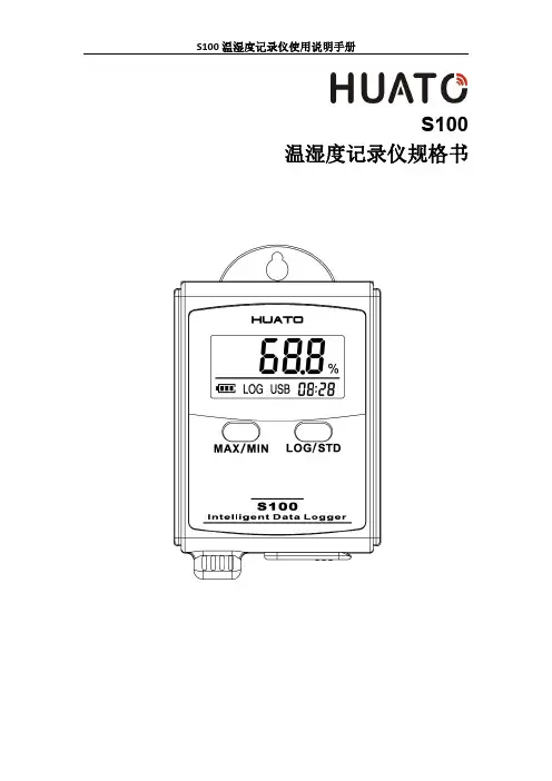
S100温湿度记录仪规格书目录第一章产品介绍 (1)1.1介绍 (1)1.2特性 (1)1.3应用环境 (1)1.4记录仪数据 (2)1.5温湿度记录仪S100-ET/S100-EX外观 (2)1.6温湿度记录仪S100-T/S100-TH外观 (3)1.7S100系列温度记录仪显示屏 (3)1.8S100系列温湿度记录仪显示屏 (4)1.9按键功能介绍 (4)1.10设备状态说明 (4)第二章软件使用指南 (7)2.1计算机硬件的要求 (7)2.2USB驱动安装 (7)2.3LogPro软件使用 (9)2.3.1读取和设置记录仪属性 (9)2.3.2参数设置说明 (10)2.3.3查看数据 (10)2.3.4删除数据 (11)3.1液晶屏显示暗淡 (12)3.2日期&时间错误 (12)3.3软件运行错误 (12)第一章产品介绍1.1介绍华图S100系列记录仪是华图公司最新推出的用于疫苗、冷藏运输、低温冷库等场所的具有国内领先水平的温度测量仪器,采用原装进口之温湿度传感器,精度高,一致性非常好,两节1.5V7号电池供电,连续工作时间达6个月以上,是国家技术监督总局认可的计量仪器。
1.2特性(1)外形小巧精致,使用方便;(2)传感器由瑞士生产,精度高;(3)2节1.5V7号电池可以工作6个月以上,25℃环境(采样间隔60秒,记录间隔300秒);(4)主机尺寸:57x92x20mm;(5)LCD屏幕尺寸:37x17mm;(6)温度和湿度外探针直径:16mm;(7)温度外探头直径:6mm;1.3应用环境(1)疫苗(2)冷藏运输(3)低温冷库(4)工作及生活区域(5)超市1.4记录仪数据1.5温湿度记录仪S100-ET/S100-EX外观LCD显示区型号标签LOG/STD:记录和开关机按键电池盖,打开可更换电池MIN/MIN:最大最小值查看按键USB接口外置传感器接口外置温湿度传感器(S100-EX/S100-EX+)挂孔外置温度传感器(S100-ET/S100-ET+)1.6温湿度记录仪S100-T/S100-TH外观LCD显示屏挂孔LOG/STD按键型号标签MAX/MIN按键电池盖传感器USB端口1.7S100系列温度记录仪显示屏温湿度数值显示区域USB连接标志记录过程中的最大值显示年-月日-时分切换显示记录过程中的最小值华氏度单位符号电池电量摄氏度单位符号记录状态标志1.8S100系列温湿度记录仪显示屏温湿度数值显示区域USB连接标志记录过程中的最大值显示年-月日-时分切换显示记录过程中的最小值湿度单位符号电池电量华氏度单位符号记录状态标志摄氏度单位符号1.9按键功能介绍:进行当前值与记录过程中的最大值、最小值切换(数值锁定);:设备关机时,长按5S后开机进入待机模式,再按3S进入记录模式;记录模式下,按3S可进入待机模式(仅进入待机模式),在待机模式下,按5S 关闭设备。
温湿度计使用方法说明书一、产品概述温湿度计是一种用于测量环境温度和湿度的仪器。
本说明书将介绍如何正确使用温湿度计,帮助用户快速掌握其功能与操作。
二、产品特点1.精准测量:采用高精度传感器,可准确测量环境温度和湿度。
2.便捷携带:小巧轻便的设计,方便携带。
3.多功能显示:LCD显示屏显示温度和湿度,并可切换温度单位(摄氏度/华氏度)。
4.数据保存:可记录最大和最小温湿度值。
5.自动关闭:设定自动关闭时间,节省电量。
三、使用方法1.打开/关闭按下电源开关,屏幕将亮起显示当前温度和湿度。
再次按下电源开关,屏幕将关闭。
2.温湿度单位切换按下“单位”按钮,屏幕将显示当前的温度单位,再次按下将切换到另一个单位。
3.最大/最小值记录按下“MAX/MIN”按钮,屏幕将显示当前测量范围内的最高温度和湿度值。
再次按下将显示最低温度和湿度值。
4.自动关闭设置按下“SET”按钮,然后使用“上下”按钮选择自动关闭的时间。
再次按下“SET”按钮确认设置。
温湿度计将在设定的时间后自动关闭。
四、注意事项1.请勿将温湿度计暴露在高温、低温、潮湿或受到阳光直射的环境下,以免影响测量结果和仪器寿命。
2.测量时,请确保温湿度计的传感器不受阻挡,避免影响测量准确性。
3.不要将温湿度计用于液体测量或接触尖锐物体,以免损坏仪器。
4.请定期清洁温湿度计表面,并使用柔软的布进行擦拭,以保持仪器的外观和使用寿命。
5.长时间不使用时,请关闭温湿度计以节省电量。
五、故障排除1.屏幕不显示:请检查电池是否正常安装,如果电池电量不足,请更换电池。
2.显示不准确:请确保温湿度计不受干扰,如周围有电磁场干扰,请移动到其他位置进行测量。
3.其他问题:如有其他问题,请联系售后服务中心获取技术支持和解决方案。
六、维护保养1.请定期更换电池以确保仪器正常运行。
2.避免将温湿度计与尖锐物体接触,以免损坏传感器或表面。
3.避免将温湿度计长时间暴露在高温、低温、潮湿的环境中,以保持测量的准确性。
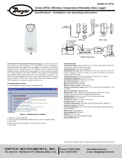
Specifications - Installation and Operating InstructionsBulletin PC-WTDLSPECIFICATIONSTemperature Range: WTDL-10/WTDL-20: -4 to 176°F (-20 to 80°C); WTDL-30:-328 to 500°F (-200°C TO 260°C) for probe.Humidity Range:WTDL-20: 0 to 95% RH.Temperature Accuracy: WTDL-10/WTDL-20: 0.9°F (0.5°C) from 32 to 122°F (0to 50°C); WTDL-30: 0.18°F (0.1°C) from -4 to 176°F (-20 to 80°C), 0.9°F (0.5°C)outside of specified range.Humidity Accuracy: WTDL-20: ±3.0% RH, ±2% typical at 77°F (25°C). Temperature Resolution: 0.018°F (0.01°C).Humidity Resolution: WTDL-20 only: 0.1% RH.RF Carrier Frequency: 2.45 GHz.Band: ISM band 2.405-2.48 GHz.Maximum Power Output: +0 dBm typical.Wireless Transmission Range: 2000´ (610 m) outdoors, line of sight; 500´ (152m) indoors.Receiver Sensitivity: -95 dBm typical.Memory Size: WTDL-10/WTDL-30: 30,000 Readings; WTDL-20: 15,000readings per channel, software configurable memory wrap.Sampling Method: Stop on memory full or continuous recording.Sampling Rate: 2 sec to 24 hrs.Temperature Limits: -4 to 176°F (-20 to 80°C).Humidity Limits:0 to 95% RH.Computer Requirements: Windows ®Xp Sp3, Windows Vista ®, Windows ®puter Interface: WTDL-RX.Power Requirements: 3.6 V TL-5104 lithium metal battery, installed functional,user replaceable.Battery Life: 2 years (approx.).Housing Material: ABS plastic.Weight:0.25 lb (113.4 g).FCC Approval: FCC ID# OA3MRF24J40MA.Agency Approvals: CE.The Series WTDL Temperature/Humidity Data Logger is perfect for applications which require real time monitoring, or in areas that are not as accessible to periodically retrieve the loggers. The data loggers can transmit up to 500 feet indoors and up to 2000 feet outdoors. The distance can be increased by using additional receivers. Wireless data is transmitted on a 2.4 GHz frequency allowing it to be used anywhere in the world. A network of data loggers can be separated into a smaller subnet. These subnets can all be controlled by a single PC. The Series WTDL data loggers also feature a user programmable alarm. This alarm can be configured to show an on screen alarm, send a text message (standard SMS rates apply) or an email if an alarm condition is met.SOFTWARE INSTALLATION1. Insert installation software and click install Dwyer2.00.2. Follow on screen instructions.3. Next, click on the Install USB Interface Drivers on the CD contents screen.4. Click Install.5. Next, click on Install RFLogNET on the CD contents screen.6. Click Install.Figure 1: Software/Driver InstallerWindows ®and Windows Vista ®are registered trademarks of Microsoft Corporation[9.40]1-17/64[32.00][10.67]180° HORIZONTALWTDL-30Wireless Transceiver WTDL-10/20Figure 1: Backside of data logger showing power switch**For more information on using the WTDL-RX software, please consult the softwaremanual found on the CD.BATTERYThe battery is user replaceable and has a typical battery life of 2 years. To replace thebattery, remove the backside of the data logger and take the battery out. Replace thebackside of the data logger. Shorter sample rates will considerably shorten the batterylife. To preserve battery life, it is recommended to use the longest practical sampling Figure 2: RFLogNet Data Logger Configurator©Copyright 2013 Dwyer Instruments, Inc.Printed in U.S.A. 10/13FR# R6-444062-00。
温度采集说明1.整体说明本系统的主要功能是多点温度采集,系统由一个读卡器。
多个采集器和上位机软件构成。
采集器负责采集温湿度数据,并通过ZigBee无线网络将数据上传到读卡器中,读卡器与PC 机连接,其负责将接收采集器的上传的数据,并且将上位机的指令发送给采集器。
上位机软件可以将读卡器读取到的数据显示出来,并经行统计,同时还能对采集器经行配置。
2.准备工作>模块与底板连接方法[请暂时不要接入电脑]USB底板接法注意:USB板可以直接接入电脑的USB接口。
B底板接入电脑4.打开电脑,安装USB转串口驱动USB转串口驱动程序安装的方法和步骤和仿真器驱动的安装基本相同,但首次使用USB转串口的时候,系统会自动找到硬件,请不要选择自动安装,将光盘中的驱动程序拷贝到硬盘中,然后找到驱动程序位置,安装,如下图所示。
系统安装完驱动后提示完成对话框,点击完成退出安装 查看和修改USB转串口的串口端口号[注意:不推荐使用com1-3,如默认为com1-3,请修改]5.采集器采集器采集器分为普通模式与设置模式,普通模式下采集器每隔一个时间间隔将向读卡器上传一组温度数据,每上传十组数据采集器自动上传一组硬件信息帧。
按下采集侧面的按键时采集器进入配置模式,用户此时可以通过上位机软件配置采集器。
传感器采集器6.读卡器读卡器由一个ZigBee模块与一个USB底板组成,读卡器也分为两种模式:透传模式和ModBus模式。
透传模式下读卡器直接将接收到的采集器数据发送给上位机,若处于MdoBus 模式,则读卡器将接收到的数据保存,直到上位机发除读取命令时,才将数据发送给上位机。
Ps:第一次接入USB底板可能需要安装驱动,安装流程见上文。
7.上位机采集器的数据显示与采集器设置都通过上位机软件来实现。
具体操作如下:打开上位机软件打开后界面如下图:设置连接参数。
连接成功后软件进入检测界面。
界面说明如下:右键点击采集器部分可查看具体曲线图(请选择没有文字显示的部分点击右键)。
KH-1058型温湿度记录仪 使用说明书珠海市锦河贸易有限公司2010.09装箱单名称 型号 单位 数量台 1温湿度记录仪 KH-1058__说明书 本 1电源转换器 AC220V-DC5V只 1温度传感器 只 1目录一、主要技术指标 (1)二、各部分名称及功能 (2)三、安装 (3)四、显示方式 (4)五、历史数据操作 (5)六、参数设置 (4)6.1通道参数设置 (6)6.2记录参数设置 (7)6.3打印参数设置 (7)6.4日期时间设置 (8)6.5继电器参数设置 (9)6.6短信参数设置 (10)6.7基本参数设置 (11)6.8退出参数设置 (12)七、短信通讯 (13)八、故障处理 (15)KH-1058系列温湿度记录仪具有数据采集、显示、记录、查询、通讯等基本功能。
可扩展继电器控制、打印、短信等可选功能。
主要适用于冷藏库、冷冻库、保觧库、速冻库、药品库、粮库、电子厂、计算机房、制药厂等场所的温湿度监控记录,是企业商检注册、质量体系认证、出口达标、科学管理的必备产品。
一、技术指标与型号定义1.1 主要技术指标1.1.1 测量范围温度:-50℃ - +120℃。
温度(湿度):-40℃-100℃湿度:0- 100%RH1.1.2 测量分辨率温度:0.1℃温度(湿度):0.1℃湿度:1%RH1.1.3 打印功能(可选)定时数据打印报警数据打印历史数据打印1.1.4 短信功能(可选)发送定时短信发送报警短信报警拨号短信查询1.1.5 无线通讯功能(可选)最大1800米传输距离410M-950M工作频率1.1.6 显示功能当前数据显示,报警指示历史数据显示1.1.7 存贮功能:存储容量:32K-224K。
存贮频次:1次/分钟 - 1次/24小时。
1.1.8 继电器功能(可选)8种控制方式:报警控制上限报警控制下限报警控制加热加湿控制制冷除湿控制按键控制时间间隔控制串口控制。
1继电器容量:5A 240VAC1.1.10:充电电池(可选)电池容量:700mAh注意:内部锂电池只能用于掉电后使记录仪保持原来的参数运行。
无线温湿度智能监测系统软件使用说明书(V1.1)目录1系统概述 (1)1.1系统组成 (1)1.2节点概述 (1)2 软件运行环境 (2)2.1 软件环境 (2)2.2 硬件环境 (2)3 系统软件使用和操作 (3)3.1 安装QF03-A103总控端驱动驱动 (3)3.2 安装监测软件 (5)3.4卸载监测软件 (6)3.3 运行监测软件 (6)4注意事项 (10)5保管存放 (11)1系统概述1.1系统组成无线温湿度智能监测系统采用低功耗设计,具有体积小、节能、安全、安装简单、工作稳定等优点,是一个低成本、高性能、可常年不间断运行的无线传感网络系统,维护简单,使用方便。
无线温湿度采集终端能够任意安装在所需监测的地方,适合应用于需监测的军事区域、仓库、血液中心血库、厂房、机房、孵房、温室等对环境温湿度要求高的场合。
无线温湿度智能监测系统由若干无线温湿度采集终端、无线路由节点、一个总控端和监测中心监测管理软件组成。
系统总体结构如图1所示。
图1 无线温湿度智能监测系统拓扑结构1.2节点概述(1) 无线温湿度采集终端采集终端是两节1.5V普通干电池供电的低功耗的传感器节点,置于所测环境中进行温湿度数据的采集和预处理,并将数据上传给路由节点或总控端,呈星形拓扑结构排列,安装实施相对简单,可以节省费用,控制成本,具有很大的环境适应性。
用电池供电,能够工作一年以上。
任何采集终端在网络覆盖范围内可以自动加入或退出网络,且无需设置自动入网。
安装使用:安装方式,根据现场实际可以采用摆放、螺丝固定等方式。
采集终端要布置在无线路由或者总控端周围通信距离可视范围之内,采集终端周围应避免有大面积金属遮挡物。
在监测特别重要和密集的区域可以多放置几个采集终端。
(2) 路由节点路由节点负责整个网络的数据中继、覆盖延伸功能。
路由节点之间呈Mesh网状网络拓扑结构,其路由可自动建立和维护,具有强大的功能;网络可以通过“多级跳”的方式通信;组成极为复杂的网络;具备自组织、自愈功能。
S400W 系列无线温湿度记录仪用户手册目录第一章产品介绍 (1)1.1产品特点 (1)1.2使用范围 (1)1.3性能参数 (2)1.4HE2400&HE2410无线基站外观示意图 (3)1.5S400W系列无线记录仪带LCD显示 (4)1.6S400W系列LCD符号说明 (4)1.7S400W-ND系列无线温湿度记录仪不带LCD显示 (5)1.8安装电池 (5)第二章软件使用指南 (6)2.1安装软件 (6)2.2设置HE2400无线基站的RJ45模块 (6)2.3ToMonitor软件使用 (7)2.3.1打开运行软件 (7)2.3.2系统设置 (8)2.3.4通讯设置 (8)2.3.5用户管理 (9)2.3.6分区管理 (9)2.3.7设备管理 (10)2.3.8实时曲线按钮 (11)2.3.9文本显示按钮 (12)2.3.10前一区域/后一区域按钮 (12)2.3.11监测列表按钮 (12)2.4查看导出上传的数据 (12)第三章使用注意事项 (14)3.1注意事项 (14)3.2常见故障 (14)第一章产品介绍S400无线温湿度记录仪是H U A TO公司汲取国外同类产品优点并结合我国特点自助设计一款高速、智能的温湿度记录仪。
该仪器采用无线数据传输方式采集和记录温湿度数据。
它自带记录内存,可存储8192组数据,能实现对仓库、实验室、冰箱、冷库等环境的远程实时监测,采用2.4G无线网络发送数据,无需布线,操作简单,性能可靠。
1.1产品特点(1)Zigbee转RJ45无线中继技术参数●无线传输速率:115200bps。
●可连接无线记录仪终端数目64台。
●支持频段数目:15个频段●无线接口:Zigbee自组网,自动寻找最优链路传输数据●内置RJ45接口,将接收的无线数据从局域网传输到服务器●可同时作为中继/网关使用,用于接受无线温湿度记录仪发送的无线信号●电源:12V DC电源(2)无线记录仪技术参数●无线传输速率:115200bps。
RCW-800Wifi 使用说明书目录第一章产品介绍 (2)1.1产品概述 (2)1.2产品特点 (2)第二章技术指标 (2)第三章使用指南 (3)1.1报警监测仪使用指南 (3)1.1.1产品显示: (3)1.1.2按键说明 (3)1.1.3指示灯说明: (4)1.1.4界面说明: (4)1.1.5连接无线网: (7)1.2云平台使用指南 (9)1.2.1平台注册: (9)1.2.2平台登录 (10)1.2.3添加设备 (10)1.2.4设备参数设置 (11)1.2.5创建项目 (12)1.2.6浏览项目 (13)第四章注意事项 (15)第五章附件说明 (15)第一章产品介绍1.1产品概述RCW-800WIIF库狗温湿度远程报警仪,是一款基于物联网技术的高新技术产品,产品广泛应用于食品、餐饮、物流以及HACCP体系认证的行业。
通过WIFI数据传输方式,结合冷链物联网平台,客户通过浏览器或者智能手机终端在线实现实时监控数据远程查看和管理数据。
同时还可以通过平台报警,蜂鸣器报警提示功能。
RCW-800WIIF为1温1湿类型,设备内置充电锂电池,断电仍可提供实时数据上传、平台报警服务。
1.2产品特点●采用高灵敏度探头,反应快,灵敏度高。
●断电续航,内置电池可持续工作至少6小时。
●可设定温湿度报警阈值,超出设定阈值LED灯闪烁、蜂鸣器鸣叫等提示报警。
●可设定上传间隔时间,自由控制数据记录。
●报警仪本机可记录20000组数据,服务器不受存储组数限制。
●连接Wifi接入点,采集数据实时上传云平台。
●灵活导出数据,可通过云平台导出多种格式数据。
第二章技术指标产品型号:RCW-800Wifi供电电源:5V/1A(DC)测温范围:-40℃~+80℃测温精度:-20℃~+40℃:±0.5℃;其他±1℃温度显示分辨率:0.1℃温度传感器类型:NTC热敏电阻温度传感器线长:5米;测湿范围:10%RH~95%RH测湿精度:±5%RH湿度显示分辨率:0.1%RH湿度传感器类型:霍尼韦尔湿度传感器线长:2米上传间隔时间:1分钟~24小时离线记录容量:20000组报警输出:LED指示灯、蜂鸣器、平台提示通信接口:Wifi备用电池:3.7V 1100mAh 锂电池第三章使用指南1.1 报警监测仪使用指南1.1.1 产品显示:1.1.2 按键说明1) 触控按键:a) 【】:进入菜单、确定选中项; b) 【】、【】选择键:选择菜单选项,点击上选择键,选中上一个选择;点击下选择键,选中下一个选项;当光标到最上面或最下面时,按上键或下键循环显示; c)【】、【】选择键:更改参数值,点击左选择键,参数值减小;点击右选择键,参数值增大;当光标到最上面或最下面时,按上键或下键循环显示; d) 【】:退出当前界面,返回上一界面;2) 亮屏键\熄屏键:当LCD 屏亮时,按击亮屏键 LCD 屏幕熄灭,当LCD 屏灭时,按击亮屏键 LCD 屏幕亮; 3) 开关键:通过拨动拨码开关控制设备开关机; 4) 复位按键:按住复位键4秒,Wifi 接入点恢复出厂默认值,可重新连接WIFI 设置;当前时间报警指示触控按键锁屏键采集显示区1.1.3指示灯说明:1)电源指示灯:外部电源接通时,电源指示灯(绿色)常亮;无外接电源,由电池对设备供电时电源指示灯熄灭;2)报警指示灯:正常状态时不亮,超限报警时,指示灯(红色)以每秒1次的频率闪烁;1.1.4界面说明:1)开机画面:开关机:1.如果需要开机,滑动设备背面开关机键,设备开机并显示开机画面;2.如果需要关机,再次滑动开关机键即可;2)主界面:1.开机后,跳过开机画面,自动进入主界面;2.点击【】键进入参数设置主界面;3)参数设置主界面:1.点击【】、【】键切换选择菜单项;2.点击【】键进入选中菜单项界面;3.点击【】键返回主界面;4.点击【】、【】键无反应;4)报警参数设置:1.温度报警范围:-40℃~70℃;湿度报警范围:10%~95%;2.点击【】、【】键切换选择参数项;3.点击【】、【】键循环改变选中参数项的参数值,步进为1增加或减少;4.点击【】键保存参数并返回参数设置界面;5.点击【】、【】键无反应;5)数据传输功能:1.数据传输功能:包含开启和关闭两个参数值,默认开启;2.数据上传间隔:参数范围 1min~ 60分钟,默认1分钟;若需要设置超过60分钟的上传间隔时间,可通过平台设置参数,最大可设置为24小时;若上传间隔时间已设置超过60分钟,通过按键修改参数时,界面参数值显示为60;3.点击【】、【】键切换选择参数项;4.点击【】、【】键循环改变选中参数项的参数值;5.点击【】键保存参数并返回参数设置界面;6.点击【】键无反应6)语言选择和待机时间:1.语言选择:包含中文和英文两个参数值,默认英文;2.屏幕待机:包含1分钟、5分钟、关闭3个参数值;3.点击【】、【】键切换选择参数项;4.点击【】、【】键循环改变选中菜单项的参数值;5.点击【】键保存参数并返回参数设置界面;6.点击【】键无反应;7)恢复出厂设置:1.恢复出厂设置:包含是和否2个参数值;2.点击【】、【】无反应;3.点击【】、【】键循环改变选中菜单项的参数值;4.当菜单值为“是”,点击【】,弹出是否恢复出厂设置确认界面,点击【】,设备重启,参数值恢复出厂设置。
目录一、系统概述-------------------------------------------- 21、系统网络简介2、仪器说明3、无线记录仪使用领域4、配件清单二、技术特性--------------------------------------------- 51、主要特点2、技术参数三、仪器安装--------------------------------------------- 61、主机安装2、终端接收器安装3、中转器安装4、PC 软件安装四、系统使用与操作-------------------------------------- 101、使用前准备与检查2、按键功能说明3、系统全自动组网4、软件使用说明与操作五、故障分析与处理------------------------------------- 281、无线温湿度记录仪主机故障分析2、终端接收器故障分析六、售后服务-------------------------------------------- 291、日常维护2、返修校准3、售后服务联系1无线系统中文使用说明书一、系统概述1、系统网络简介:199无线系统是一个由无线温湿度记录仪、中转器及终端接收器组成的无线网络系统。
本系统只能存在一个终端接收器,可以有多个中转器,中转网络可达5 层级连,无线温湿度记录仪为低功耗模式(可使用电池供电,也可使用常备电源供电)并可全自动组网。
GPRS 功能可随时随地将指定信息发送到已绑定手机上,以真正实现实时监控功能。
(图1:无线记录仪系统布局图示意图)2无线系统中文使用说明书2、仪器说明1.1 无线温湿度记录仪说明(图2:无线温湿度记录仪主机)产品型号:无线温湿度记录仪199-WTH无线单温度记录仪199-WT111.2 终端接收器与中转器屏幕显示说明(图3:终端接收器显示)上电后屏幕上出现如图所示的3行文字时表示仪器正确启动。
第一行是仪器类型;第二行显示字符“ID:”,当中转器不在网络中时显示“Failed”;第三行是16个字母的ID号。
终端接收器型号:199-TR中转器型号:199-RE3、无线记录仪使用领域Apresys无线温湿度记录仪,严格意义上说来,更是一套无线温湿度监控系统。
利用成熟的2.4G 无线网络现实通讯,实现长距离(点到点视距500-1000 米,网络覆盖可达五平方公里)、多点(≤500 结点)的局域环境温湿度监控,更利用GPRS 通讯技术,实现跨地区、省市甚至跨国际的环境温湿度远程控制。
与传统无线技术相比,有了质的飞跃。
常见应用领域有:大型冷库、冷藏运输车温湿度监控大型药厂、食品厂、化工厂、精密电子厂环境温湿度监控蔬菜大棚、畜牧业养植基地环境温湿度监控博物馆、档案室、气象局、血库、医院、实验室环境温湿度控制4、配件清单标配件:1)无线温湿度记录仪一台2)2.4G天线一条3)工业电池三节4)USB数据线一条5)外接探头一条6)电源适配器一个7)软件光盘一份8)使用说明书一本9)产品质保卡一本选配件:1)终端接收器2)中转器3)GPRS模块及软件4)RFID模块及软件4无线系统中文使用说明书二、技术特性1、主要特点单结点连GPRS 模块或终端接收器统一连GPRS 模块,以实现与手机双向通讯;自动组网,最高5级中转设置,使网络覆盖面积成倍扩大;通过手机或PC端软件统一管理结点网络,使操作更简单,大大提高工作效率。
2、技术参数温度采样间隔5 秒到24 小时任意时间间隔发送数据时间间隔1 分到24 小时任意时间间隔电源外接电源+3.6V、2400mAh锂锰电池(可更换)报警软件上温湿度报警、低电量报警,手机短信温湿度报警电池寿命2-3 年(视采样频率和数据传输方式而定)采集器容量10 万组数据数据传输2.4G 无线传输+GPRS 数据传输+USB 有线传输温、湿度量程-40℃to 100℃/ 1%RH to 100%RH温、湿精度±0.5℃/ ±3%RH液晶显示功能仪器ID、温度、湿度、电量、信号强度、记录状态、时间PC 终端功能同时监控500 个以内的数据采集器可对每个数据采集器单独设置(命名、温湿度上下限设置、启动停止记录、数据读取)可显示温、湿度数据列表和数据趋势图可将数据方便快捷的转换为Excel文档网络管理功能不超过500个结点的局域网ID 号匹配验证功能(提前在PC 端输入采集ID 号才能联网)邻节点传输距离300m 非视距1000m 视距无线电波频率2.4GHz环境温度-40 to 100℃;1%RH to 100%RH尺寸140mm*70mm*20mm重量160 克5无线系统中文使用说明书三、仪器安装1、记录仪安装1.1将天线固定在记录仪主机上;1.2将外置探头固定在主机上;1.3装入电池;1.4 记录仪和接收器尽量置于可视范围内,尽可能避免金属障碍,保持通信顺畅,尽量用9V外接直流电源供电;1.5用钉子固定,挂在所测点;1.6将天线角度调整到信号最强。
2、终端接收器安装1.1将天线固定在接收器上,天线方向与接收器正面垂直;1.2连接电源(USB电源或9V 直流电源)1.3 将USB数据线与电脑连接。
3、中转器安装1.1与记录仪安装相同;1.2必须使用USB电源或9V 直流电源。
4、PC 软件安装4.1双击软件安装图标:34.2 选择软件语言,中文系统选中文,非中文系统选英文:6无线系统中文使用说明书4.3点击下一步4.4软件自动安装中,点击安装7无线系统中文使用说明书4.5软件安装完成,请选择232 转USB驱动。
4.6 出现安装画面,稍等数秒,出现“Press enter”提示后后按Enter.,4.7 出现桌面快捷方式图标8无线系统中文使用说明书4.8双击图标后显示登录界面,请输入初始帐户及密码初始ID: admin初始Password:apresys输完后点击:,即可使用无线系统软件9无线系统中文使用说明书四、系统使用与操作1、使用前准备与检查1.1 天线:查看天线是否完好,是否有松动,调整好天线的方向;1.2 传感器:终端记录仪需要接上传感器才能使用;1.3 电源:终端接收器与中转器都需要使用常备电源供电,有两种接入常备电源的方法,a、直接使用USB取电,b、通过9V DC电源插座接入;1.4 终端记录仪可安装3 节3.6V电池或者接常备电源使用;2、按键功能说明无线温湿度记录仪屏幕点亮30秒后会自动关闭。
右键功能:点亮屏幕。
左键功能:只有当屏幕点亮时左键才有效。
如果仪器已在网络中,按下左键将刷新RF信号状态5秒。
如果仪器不在网络中且仪器位于网络的有效信号内,连续按下左键几次,仪器将自动加入网络。
3、系统全自动组网当仪器位于网络的有效信号内时都会自动加入网络。
终端接收器为低功耗模式时,将会在5分钟内自动加入到网络中。
4、软件使用说明与操作4.1 登录软件后,出现仪器管理主界面:10无线系统中文使用说明书4.1.1 建立终端接收器与软件通讯4.1.2 报警显示4.1.3 最新消息显示4.1.4 仪器管理功能键说明a.添加:添加新的设备,请正确输入仪器屏幕上的ID号;请优先输入终端接收器ID号。
b. 添加完毕后显示:11 无线系统中文使用说明书c.删除:删除勾选的设备;d.刷新:刷新选中的网络设备,以获取仪器最新的连接状态;e.退网:仪器退出网络;f.设置名称:修改选中仪器的名称;12无线系统中文使用说明书4.2即时数据界面4.2.1 即时数据主界面注:第一次使用该软件时,会自动弹出一个窗口,必须先建立数据库。
数据库存在安装目录下,在已建有数据库的情况下,不再弹出此窗口。
数据库将自动把所有记录过的数据按类存储。
一个数据库的容量为2G,如果超过2G,数据满溢,无法存入,则需建立新的数据库。
13无线系统中文使用说明书4.2.2 即时数据功能键说明:a.启动即时数据:设置间隔参数后,勾选所需启动仪器,可完成批量启动即时数据b.停止即时数据:将停止显示选中记录仪的即时数据;14无线系统中文使用说明书c.修改间隔参数:设置即时数据显示时间间隔,默认状态为1分;d.单次数据获取:将获取所选仪器的单次即时数据e.取消操作:将取消还未开始执行的工作指令4.2.3 即时数据界面功能键说明双击左面仪器列表行,将显示对应的即时数据信息。
15无线系统中文使用说明书a. 曲线:显示曲线即时数据趋势图b. 数据:显示即时数据列表c. :曲线按横坐标放大d. :曲线按横坐标缩小红线代表通道1曲线,黄线代表通道2曲线;点击曲线上方的复选框,可以开关曲线显示。
4.3 启动管理界面4.3.1 启动管理主界面图16无线系统中文使用说明书4.3.2 逐个设置仪器启动时间(可延后)、间隔时间,报警范围4.3.3 启动管理功能键说明:a. 启动记录:可批量或单个启动所勾选的仪器,启动仪器后,仪器内原有数据将被覆盖。
如需重新启动记录仪,请先下载原有数据!17无线系统中文使用说明书b. 停止记录:可批量或单个停止所勾选仪器的记录状态;c. 设置报警:可重新设置报警范围d. 取消操作:将取消尚未执行的指令4.4 下载管理界面4.4.1 下载管理界面图示18无线系统中文使用说明书54.4.2 仪器下载设置:可按照需求选择每天定时、指定时间下载数据,如选无计划,则可手动下载。
194.4.3 设置模式:可下载全部数据,也可下载指定时间段的数据。
4.4.4 下载管理功能键说明:无线系统中文使用说明书a.下载数据:可批量或单个下载所有勾选的仪器历史数据;绿色进度条完成时,表示下载完成,可能需稍侯数分钟;b.取消下载:将取消尚未执行的指令操作。
204.5 历史数据界面4.5.1 历史数据界面图无线系统中文使用说明书勾选或单击所需操作的仪器,将出现该台仪器的历史数据列表,再双击历史数据列表行,会显示对应的历史数据信息。
4.5.2 设置所需操作的时间段,默认值为全部记录时间段;4.5.3 历史数据功能键说明:21a. 打印数据:分页打印所有历史数据,分为曲线打印和文本数据打印两种;默认A4纸张,打印时可重新设置纸张大小。
无线系统中文使用说明书22b.另存为:将所选仪器的历史数据保存,有软件格式和EXCEL 格式,两种格式可选。
建议使用软件.aprz格式。
无线系统中文使用说明书c. 打开文件:打开已保存过的数据文件,通过软件打开的文件只识别.aprz.234.5.4 历史数据显示模示分为三种,曲线、数据及概述a.曲线显示无线系统中文使用说明书b.数据显示24c.概述显示无线系统中文使用说明书4.5.5 按放大及缩小键可自动缩放数据坐标,移动时间条可查看任一时段的历史数据。
4.6 用户管理界面可根据实际增加用户、删除用户、修改密码;管理员权限:不仅可以使用软件各项基本功能,还可进行仪器添加、删除、退网,创建数据库等高级操作。