温度记录仪 中英对照使用说明.
- 格式:pdf
- 大小:204.41 KB
- 文档页数:6
User's manualMulti-channel temperature recorder(Smart type)08Channels16Channels24Channels32ChannelsFor sales service,please contact your local dealer.ForewordThank you for purchasing our products.In order to ensure that users can use this product correctly, please read this product manual carefully before use.Check the packing list of this manual.Recognize products and accessories.If there is any non-conformity,please contact our company or agent.Precautions1.The contents of this manual are used in conjunction with the instrument,and the contents of the version are subject to change without prior notice.2.The contents of this manual have been confirmed and the user has been able to write the easy-to-understand description of the manual in the simplest way.If you find that it is incorrect or the description is not clear,please contact our company or agent.Version:v1.5WarningFor your personal safety and proper use of this instrument,please be sure to comply with the specification requirements for operation and measure.And pay strict attention to the following safety regulations.1.The Protection of the Power and Grounding.The working power supply of this product is AC86-265V.Before start-up power supply,please confirm the matching between the power supply and the working supply,and ensure that the power supply has been grounded,to prevent electric shock,the instrument shell has received a power outlet wire.2.Please do not operate in an explosive environment,so as to avoid the explosion of personal injury.3.Please do not turn on the instrument shell,the instrument has a high voltage power in some places,to prevent electric shock.4.Do not allow the plug connection in the case of charged,so as to avoid electric shock.5.If the instrument is damaged because of violation of safety rules,the company does not undertake any responsibility.1.SummaryThe multi-channel temperature collector adopts32-bit high-speed cpu for data processing,adopts 5-inch industrial display screen,supports K J E T N S R B type thermocouples input,and various display modes.The user can read various parameters more intuitively,and the instrument has perfect functions.Superior performance and simple operation to meet the needs of production, laboratory and R&D measurement.It is widely used in the production lines,laboratories and quality inspection departments of lighting enterprises,electric tools,household appliances,electric motors,electric appliances, medicine,petroleum,chemical,metallurgy,electric power and other industries and scientific research units.Various measurement functions can be customized to meet higher application requirements. The multi-channel temperature recorder has the following features:▲5-inch industrial color display LCD screen with display resolution up to800x600dbiThe picture is clear,the color is beautiful,and the angle of view is wide.▲32-bit mcu design,more accurate measurement,faster and more stable sampling▲Multi-interface display,support real-time numerical display,time display,column display▲Support multiple sensor inputs:kjetnsrb▲The voltage difference between channels can be as high as ac/dc350v,strong anti-interference ability.▲Each channel can independently set multiple alarm values,ll(ultra low),l(too low),h(too high),hh(super high),and can output alarm through relay.▲Alarm list display,can show the time of occurrence.▲Independent temperature correction△value per channel and cold end value correction.▲Built-in8G large memory,can record up to64files,each file can record60,000sets of data, automatic cycle recording.Support local query history curve.▲With communication address code setting,it can be used inmultiple machines and parallel.It can provide communicationprotocol.▲Standard usb communication interface,optional RS232or RS485communication interface.▲With U disk interface,support U disk to download and copy records.▲Modular design,convenient for users to expand capacity▲8channels per module,this unit supports up to32channels(4modules).2.Basic principleAs shown in the figure,the instrument consists of thermocouple,photoelectric switch selector,amplifier,A/D, single-chip microcomputer,keyboard,display,communication,data memory,cold junction compensation andother components.The corresponding signal channel is selected by the photoelectric switch selector,and the signalis amplified by the signal amplifier,and then the analog signal is converted into a data signal by the ad converter tothe single-chip microcomputer for data processing,and the cold-end compensation circuit performs the normal temperature measurement to obtain the cold.The terminal temperature value,the measurement signal and the cold junction temperature value are processed by the single-chip microcomputer,and finally the correct measured temperature value is displayed on the display screen.The keyboard,communication,and data memory can be usedto analyze and store data on the display.It is also possible to connect the computer directly through the communication interface for data analysis by the computer.3.Technical indicatorsDisplay method5-inch TFT true color LCD industrial screenDisplay form Real-time list value,real-time column chart,real-time graphRecord query The history curve can be queried on this machine.Number of channels8channels per module,up to32channelsK-type thermocouple-100~1370°C Accuracy±0.05°C+0.6°CJ-type thermocouple-100~1200°C Accuracy±0.5°C+0.6°CE-type thermocouple-20~1000°C Accuracy±0.5°C+0.9°CT-type thermocouple-10~40°C Acuracy±0.5°C+0.5°CN-type thermocouple0~1300°C Accuracy±0.5°C+0.9°CS-type thermocouple300~1768°C Accuracy±0.5°C+0.6°CR type thermocouple300~1768°C Accuracy±0.5°C+0.8°CB-type thermocouple400~1820°C Accuracy±0.5°C+1°CResolution0.1℃Recording interval The computer software range is1-9999seconds,and the instrument is1-9999seconds. Communication Interface USB(standard),RS485,RS232(optional)Channel isolation AC/DC power up to350v,superior anti-interference abilityPower supply220V±10%,frequency50Hz/60Hz≤5W(standard),AC86-265V(select)≤5W(optional)4.Panel description (unit:cm)PositiveSide5.Panel descriptionFrontpanel1011.5273033U disk interfaceOperation keyboardSet:Select confirmation keywhen data is setLeft:Use cursor leftRight:Use the cursor to theright Up key:Use the cursor upDown key:Use cursor downPower switchFunction keyboard DisplayRearpanel6.Display and operating instructionsButton descriptionFunction operation keyboard:The function keyboard has a total of 5operation keys,which correspond to the operation function prompted by the display screen.The lowermost one is the interface switching function,which is displayed in sequence:real-time parameter-curve-column chart-recording-Alarm -system has a total of 6interfaces.Data setting keyboard:Data setting keyboard consists of 5buttons,which are set button,left,right,up and down ed in setting the data keyboard and setting the displacement selection.Display interfacedescriptionSetting keyboardFunction keyboardThermocouple Unit Record Cumulative timePerpetual calendar Operate indication zoneInterface information Parameterdisplay area Interface switching indicationBoot LogoThe power-on interface is displayed when power is on,and the company logo,company name,and product model information are displayed.Real-time parameter list displayThe real-time parameter interface can display multiple measurement parameters at the same time.The display interface is divided into4-channel data display and8-channel data display.16-channel data display,page-by-page pagination display,data of each channel,up to four channels of data can be displayed on the4-channel interface,and the measurement alarm status can be displayed.H/HH/L/LL.It is also possible to record the measured maximum and minimum Values.Real-time curveThe real-time curve is only displayed in real time.One page can only display8-channel curves.The real-time temperature value and corresponding channel number can also be displayed on the left side,possibly usingThe key switches another set of8-channel curves.press The key can enter the curve parameter settingsRecording curveThe recording curve is a real-time curve displayed when the recording is started,and can also be operated.Press the button to balance the movement of the curve.The recording symbol of this interface is displayed,the accumulated time will be accumulated.Historical curveThe historical curve is page-turnable,but it cannot be set.Only the total curve of the entire file can be displayed.Real-time column chartBy using the histogram method,the ratio of each channel can be compared.In the4-column chart,the actual difference between the two channels can be automatically calculated.Value,the actual measured temperature value can also be displayed in the4and8bar chartsNote:The y-axis display temperature range is the same as the curve setting range and is only set in the curve settings.Use to switch4/8/16channel display e can display multi-page parameters.Curve setting interfaceThe curve setting boundary includes a curveThe x-axis plot time,the range of the y-axis curve display,and the display curve channel can also be displayed or masked.Note:The curve time display value cannot be modified when the recording has been started.Recording interfaceStart/stop recording button.When the start button is pressed,the“Continue to continue”interface will pop up. When“Yes”is selected,the recording will be executed,the recording symbol will become,the time will startto accumulate,and the time will be counted.stop.Record settingRecord interval setting,the setting range is1-9999seconds.File formatting is to format all current log files,and all records can be erased after formatting.File export,this operation is to directly import all the records into the u disk at a time.Then import it from the PC software of pc.Perform data analysis.The recorded files support u disk export,and also support direct connection pc export.Alarm settingIn the alarm interface,you can view all current alarm status information,and you can view the page when multiple recordings.Alarm value settingIn these interfaces,you can directly set the super high value(HH)\too high value(H)\too low value(L)\Ultra low value(LL).You can use the operation keyboard to move the cursor directly to select the pop-up data keyboard for numerical setting.System settingThe system settings provide a rich set of menus that are clear and easy to use.Provided date and time, measurement speed,display language,unit of measure,sensor type,buzzer sound,communication place Address, communication baud rate,backlight time(0is long light,1-999seconds to turn off the backlight).Note:The time and date,measurement speed,unit of measure,and sensor cannot be changed when the recording is started.△value correction settingThis interface provides a correction setting for each channel△v alues,and can display the current measured temperature values for each channel,in the end the change value,can see the changes of the current value of real time,can be corrected to the actual measured value.The need to change,press the Enter key,each channel△value position can be changed into numerical red,press the arrow keys to one decimal place and,according to the left and right keys to add and subtract in bits.7.Software operating instructionsFind files in U disk Run the installation directly,as followsAfter the installation is completed,then the USB driver installation After installation,see one on the desktop Icon,Click this icon to run the software program.Enter boot interfaceThe first connection between the computer and the instrument,install the driver in the file list,and then choose the correct COM in the soft interface,the main interface in the lower left corner of the communication connection is successful.Computer interface provides a wealth of display and analysisfunctions,you can display a list of files,curve analysis shows that the list of data,real-time temperature list, instrument operation button functionList of documents are listed:serial number,record time,file name,the number of data,a large number of filesCurve labels can be detailed analysis of all the data in the file,You can use the mouse directly to zoom in and out of the curveYou can change the color of each channel in the curveYou can customize the name for each channelThe list of data can be displayed for each channel and each time interval.The user can directly open the*.CSV file directly with the EXCEL.Real time data list can display the current measured value in realThe instrument can be used directly to the remote operation of the button page.Verification conditionProject Reference ratio or range Reference ratio or range Ambient temperature℃20±5Ambient humidity RH45~75Atmospheric pressure KPa86~106AC supply voltage V220or86-265±2% AC power supply frequency Hz50±1%AC power supply waveform Sine waveß=0.05External electromagneticinterference Should avoidAeration Good ventilationSunlight exposure Avoid directPacking listHost1PCSPower cord1PCSUse manual1PCS Certificate of conformity Warranty card1PCS Thermocouple wire1PCSProduct certificateProduct name:Multichannel temperature recorderProduct model:Product number:Date:Examination clerk:Verification conclusion:Product warranty card●Warranty description:1.Warranty period within24months from the date of purchase2.Warranty equipment in the warranty period,in the normal use and maintenance of the case,the instrument problems,after inspection,the company will provide free repair and replacement parts.●The following conditions are not free maintenance1products from the company's technical personnel to repair,change,modification,the userto replace any of the internal parts.2serial number has been altered or inconsistent with the specified3damage caused by the infiltration of water or other substances into the machine●The company may also provide maintenance services,which require more than a free warrantyName ModelTel Purchase dateAddress NumberOverhaul date Maintenance record Maintenance man。

M T HERMOMETER- LX-26 M ODELE N G L ICONTENTSI.S AFETY PRECAUTIONS (3)II.I NTRODUCTION (4)III.P RECAUTIONS BEFORE USE (4)IV.O PERATING P RINCIPLE (5)T HE DIFFERENT METHODS OF TEMPERATURE MEASUREMENT (5)N ORMAL TEMPERATURES ACCORDING TO MEASUREMENT METHOD (6)A DVANTAGES OF TEMPORAL ARTERY (TA) TEMPERATURE (7)N ORMAL TEMPERATURE ACCORDING TO AGE (7)P RACTICAL CONSIDERATIONS WHEN TAKING A TEMPERATURE (7)H OW TO TAKE A TEMPERATURE (8)C ONSTRAINTS (8)V.D ESCRIPTION OF THE T HERMO F LASH LX-26 (9)VI.F UNCTIONS (11)VII.U SE (11)VIII.S ETTING &F UNCTION OF MENU (12)1.C HOOSING THE TEMPERATURE UNIT –F1M ENU (12)2. ALARME SETUP –F2M ENU (12)3.C HOICE OF DISPLAY MODE:B ODY OR S URFACE T EMP –F3M ENU (13)4.T OTAL DIFFERENCE –F4M ENU (14)5.B UZZER O N /O FF –F5M ENU (14)6.E XITING THE SETTING MODE (14)7.D ATA M EMORY (14)8.C HANGING THE BATTERIES (15)IX.T ECHNICAL C HARACTERISTICS & PRECISION (15)X.R EMARKS (16)XI.A CCESSORIES SUPPLIED (16)XII.T ROUBLESHOOTING (17)I.S AFETY PRECAUTIONS-Follow the maintenance advice stipulated in this instruction manual.-This device may be used for personal home use.-This device must only be used for the purposes described in this instruction manual.-This device must only be used in an ambient temperature range of between 10 and 40 °C.-This device must always be kept in a clean, dry area.-Do not expose this thermometer to electric shocks.-Do not expose this thermometer to extreme temperature conditions of >50°C or > - 20°C.-Do not use this device in relative humidity higher than 85%.-The protective glass over the lens is the most fragile part of the thermometer.-Do not touch the glass of the infrared lens with your fingers.-Clean the glass with a cotton bud lightly moistened with 70° alcohol.-Do not expose the thermometer to sunlight or to water.-Do not use this device outside.-Never drop the device.-Should a problem occur with your device, please contact your retailer. Do not attempt to repair this device yourself.I MPORTANT S AFEGUARDSFor your safety, ONLY use the charger supplied.Do not dismantle the device or the rechargeable base station.II.I NTRODUCTIONThe Visiomed Thermo Flash LX-26thermometer without contact has been developed using latest infrared technology. This technology allows temporal artery (TA) temperature to be taken at a distance of about 5cm away from the forehead.Precise, Instantaneous and without Contact, the Thermo Flash LX-26 is, to date, the most suitable thermometer for no risk temperature measurement. It has been demonstrated that this method of TA temperature measurement is more precise than tympanic thermometry and better tolerated than rectal thermometry (1).However, as with other types of thermometer, it is essential to use the Thermo Flash LX-26 properly in order to obtain reliable and stable results.You are therefore advised to read this instruction manual and the safety precautions carefully before use.(1) Greenes D, Fleisher G. Accuracy of a Noninvasive Temporal Artery Thermometer forUse in Infants. Arch Pediatr Adolesc Med 2001;155:376.III.P RECAUTIONS BEFORE USEThe Thermo Flash LX-26 is pre-set at the factory.It is not necessary to calibrate the device whenstarting it up.In order to obtain reliable and stable results, you are advised each time there is a significant change in the ambient temperature due to a change in environment, to allow the Thermo Flash LX-26 toacclimatise to this ambient temperature for 15 to 20 minutes before using it.It is important to allow a one minute interval between two measurements.IV.O PERATING PRINCIPLEAll objects, solid, liquid or gas, emit energy by radiation. The intensity of this energy depends on the temperature of the object. The Thermo Flash LX-26 infrared thermometer is therefore able to measure the temperature of a person by the energy the person emits. This measurement can be taken thanks to an external temperature probe on the device which permanently analyses and registers the ambient temperature. Therefore, as soon as the operator holds the thermometer near the body and activates the radiation sensor, the measurement is taken instantly by detection of the infrared heat generated by the arterial blood flow. Body heat can therefore be measured without any interference from the heat of the surrounding environment.T HE DIFFERENT METHODS OF TEMPERATURE MEASUREMENT Core temperatureCore temperature is the most precise measurement and involves measuring the temperature in the pulmonary artery by means of a catheter equipped with a thermal probe which can read the temperature in situ.The same method is employed for probes measuring the oesophageal temperature. However, such invasive temperature measurement methods require specific equipment and expertise.Rectal thermometryRectal temperature adjusts slowly in comparison to the evolution of the body’s internal temperature. It has been demonstrated that rectal temperature remains raised long after the internal temperature of the patient has started to drop and vice versa. Furthermore, rectal perforations have been known to occur as a result of this method and without appropriate sterilisation techniques, rectal thermometry can spread germs often found in faeces.Oral thermometryOral temperature is easily influenced by recent ingestion of food or drinks and by breathing through the mouth. To measure oral temperature, the mouth must remain closed and the tongue lowered for three to four minutes which is a difficult task for young children to accomplish.Axillary (armpit) temperatureAlthough it may be easy to measure axillary temperature, it has been proven that it does not provide an accurate measurement of the child’s internal temperature. To take this type of temperature, the thermometer must be wedged tightly over the axillary artery. Despite the low sensitivity and relative inaccuracy of axillary temperature in detecting fever, this method is recommended by The American Academy of Pediatrics as a screening test for fever in newborns.Tympanic thermometryIn order to obtain a precise temperature reading, good command of the measurement technique is required. The thermometer probe must be placed as close as possible to the warmest part of the external ear canal. An incorrectly placed probe could lead to a false temperature reading.NORMAL TEMPERATURES ACCORDING TO MEASUREMENT METHOD M EASUREMENT M ETHOD N ORMAL TEMP°R ECTAL36.6°C–38°CO RAL35.5°C–37.5°CA XILLARY34.7°C–37.3°CA URICULAR35.8°C–38°CT EMPORAL (T HERMO F LASH)35.8°C–37.8°CThe temperature of the human body varies throughout the day. It can also be influenced by numerous external factors: age, sex, type and thickness of skin…ADVANTAGES OF TEMPORAL ARTERY (TA) TEMPERATURE Infrared arterial temperature can be measured using a device placed on the forehead, in the temporal artery region. It has been demonstrated that this relatively new method of measuring temperature is more precise than tympanic thermometry and better tolerated than rectal thermometry.The Thermo Flash LX-26 thermometer has been designed to produce an instant forehead temperature reading without any contact with the temporal artery. As this artery is quite close to the surface of this skin and therefore accessible and given the blood flow is permanent and regular, it allows precise measurement of the temperature. This artery is linked to the heart by the carotid artery which is directly linked to the aorta. It forms part of the main trunk of the arterial system. The efficiency, speed and comfort of taking a temperature from this area make it ideal compared with other temperature measurements methods.NORMAL TEMPERATURES ACCORDING TO AGE0-2 years 36.4-38.0 97.5-100.43-10 years 36.1-37.8 97.0-100.011-65 years 35.9-37.6 96.6-99.7> 65 years 35.8-37.5 96.4-99.5P RACTICAL CONSIDERATIONS WHEN TAKING A TEMPERATURE-In order to ensure that precise and accurate temperature measurements are obtained, it is essential that each user has received adequate information on and training in the temperature measurement technique when using such a device.-It is essential to remember that although procedures such as taking a temperature may be simple they must not be trivialised. -Temperature should be taken in a neutral context. The patient must not have undertaken vigorous physical activity prior totaking his/her temperature and the room temperature must be moderate.-Be aware of physiological variations in temperature which must be taken into consideration when evaluating the results: temperature increases by 0.5C° between 6am and 3pm. Women have a temperature that is higher, on average, by around 0.2C°.Their temperature also varies in accordance with their ovarian cycle. It rises by 0.5C° in the second half of the cycle and at the early stages of pregnancy.-When sitting, temperature is lower by about 0.3 to 0.4C° than when standing.H OW TO TAKE A TEMPERATUREAim at the FOREHEAD, overthe right temporal region,from a distance of about5cm, press the thermometer’smeasurement button and thetemperature is instantlydisplayed.The reliability of themeasurement cannotbe guaranteed if thetemperature is measured overanother part of the body (e.g.arm, torso…)C ONSTRAINTSPlease observe the following before any temperature measurement to ensure a stable and reliable result:- Push back hair from the forehead- Wipe away any perspiration from the forehead- Avoid any drafts (e.g. from nasal specs, air conditioning…)- Allow a 1 minute interval between two measurements.- Each time there is a significant change in the ambient temperature due to a change in environment, to allow the Thermo Flash LX-26 to acclimatise to this ambient temperature for at least 15 minutes before using it.V.D ESCRIPTION OF THE ThermoFlash LX-26VI.F UNCTIONS1.Specially designed to take the body temperature of a personregardless of the room temperature.2.Quick and reliable results as it use the HEIMMANN infrareddetection system.3.Sound alarm if temperature is exceeded.4.Memorization of the 32 last measures.5.LCD back-lighted digital screen.6.Data displayed in Celsius or Fahrenheit.7.Automatic stop (energy saver).8.Small, convenient, easy to use.A DDITIONAL USES:ThermoFlash LX-26 can also be used to measure the temperature ofa baby-bottle or bath, or room temperature (by using the SurfaceTemp function). This function is in accordance with the Directive 89/336/EEC Electromagnetic Compatibility.VII.U SE1.Install battery2.For the first use or when insertingnew batteries wait between 10minutes for the warm-up of theapparatus and when inserting thenew batteries.3.Aim towards the forehead (see thediagram below for the ThermoFlashpositioning), from a distance of 5 cm(2 in), press the measuring key, thetemperature is displayed in 1 second.The temperature can also be takenbehind the ear lobe.4.Before taking the temperature,make sure to remove hair andperspiration from the forehead.You can also take the temperaturebehind the ear lobe.VIII.C ONFIGURATION AND FUNCTION OF MENU1.C HOOSING THE TEMPERATURE UNIT –F1F UNCTIONPress PROG SETTING button for 3 seconds, the screen displays: F1.Select ‘-’ for degrees Celsius, ‘+’ for degrees Fahrenheit.Confirm by pressing PROG SETTING button.2.A LARM SETUP –F2M ENUPress PROG SETTING button for 3 seconds, the screen displays: F1.Press twice PROG SETTING button to get F2.Select ‘+’ to increase the threshold by 0.1°C (0.1°F), ‘-’ to reduce it by 0.1°C (0.1°F).Confirm by pressing PROG SETTING button.Note: The alarm threshold default value is 38°C (100.4°F).3.C HOICE OF DISPLAY MODE:B ODY OR S URFACE T EMP –F3M ENU The ThermoFlash LX-26 is specially designed to take the body temperature of a human being.For this, use the BODY mode.Measurement range for Body mode: 32°C – 42.9°C (90°F – 109°F) You can also use the ThermoFlash LX-26 to measure the temperature of an area or an object, a food, a liquid or a room temperature.For this, use the SURFACE TEMP mode.Measurement range for Surface TEMP mode: 0°C – 60°C (32°F - 140°F)Press PROG SETTING button for 3 seconds, the screen displays: F1. Press PROG SETTING button twice to get F3.Select 0 by pressing ‘-’ button to get the BODY mode.Select 1 by pressing ‘+’ button to get the SURFACE TEMP mode Confirm by pressing PROG SETTING button.Note: The ThermoFlash LX-26 is automatically set to BODY Important: The area temperature differs from the internal body temperature. To obtain the internal temperature always use the BODY mode.Please make sure to select the BODY mode for an internal temperature reading and the SURFACE TEMP mode for an external area reading (bottle, bath, room…).4.T OTAL DIFFERENCE –F4M ENUTo adjust the total variation of your Thermoflash LX-26Press PROG SETTING button for 3 seconds, the screen displays: F1. Press PROG SETTING button three times to get F4.Select ‘+’ to increase the difference by 0.1°C (0.1°F), ‘-’ to reduce it by 0.1°C (0.1°F).Confirm by pressing PROG SETTING button.If in doubt, you are advised to leave the total variance at +0.8°C (original setting).Each time there is a significant change in the ambient temperature due to a change in environment, to allow the Thermo Flash LX-26 to acclimatise to this ambient temperature for at least 15 minutes before using it.5.B UZZER O N/O FF –F5M ENUPress PROG SETTING button for 3 seconds, the screen displays: F1. Press four times PROG SETTING button to get F5.Select ‘+’ to open the buzzer (a sound icon is displayed on the LCD screen), press ‘-’ to stop it (the icon disappear).Confirm by pressing PROG SETTING button.6.E XITING THE SETTING MODEPress PROG SETTING button until the screen turns off.7.D ATA M EMORYTo display the last temperature measurement, press simultaneously the ‘-’ and ‘+’ button.You will obtain the last temperature measurement. To switch on the last measurement, press the '+' button.The number indicated in interval of two measures corresponds to the number of measurements.Press on the button '-' for reviewTo exit data memory, press the measure key. The Thermoflash switches off in 5 seconds.8.C HANGING THE BATTERIESDisplay: when the LCD screen displays ‘Battery’, the battery is used. Operation: Open the lid and change the batteries, taking great care with the correct positioning. A mistake with this could cause damage to the apparatus and compromise the guarantee of your ThermoFlash LX-26.Never use rechargeable batteries. Use only batteries for single usage.IX.TECHNICAL CHARACTERISTICS1.Normal conditions of useOperating temperature: 10° C ῀40° C (50° ῀ 140° F)Humidity rate: ≤ 85%2.Power: DC3 V (2 batteries AA)3.Size: 196 x 150 x 50 mm – 7.7 x 5.9 x 1.9 in (L x W x H)4.Weight: 220g5.Display Resolution: 0.1° C (0.1°F)6.Measuring range:In body mode: 32°C – 42.9°C (90°F – 109°F)In Surface Temp mode: 0°C ῀ 60°C (32°F to 140°F)7.Precision: From 36°C to 39°C (96.8°F to 102.2°F) = +/-0.2°C/F8.Consumption: ≤ 50mW9.Accuracy: ± 0.3° C (0.54° F)10.Measuring distance: 5 cm – 8 cm (2 in – 3.14 in)11.Automatic stop: 5 sec.THERMOFLASH PRECISIONFrom 34°C to 35.9°C = ± 0.3°C From 93.2°F to 96.6°F =± 0.3°FFrom 36°C to 39°C = ±0.2°C From 96.8°F to 102.2°F = ±0.2°F From 39°C to 42.5°C = ± 0.3°C From 102.2°F to 108.5°F = ± 0.3°F According to ASTM Standard E1965-1998 (2003)The ThermoFlash LX-26 can take temperature readings below 32°C or above 42.9°C (90°F to 109°F) but precision is not guaranteed outside of this range.LONGEVITY USEThe ThermoFlash is guaranteed for 40.000 readings.X.A DVICE-The protective glass over the lens is the most important and fragile part of the thermometer, please take great care of it.-Clean the glass with cotton fabric, wet with water or 70° alcohol-Do not use other batteries than mentioned batteries, do not recharge non rechargeable batteries, do not throw in fire.-Remove the batteries when thermometer is not used for an extended period of time.-Do not expose the thermometer to sunlight or water.-An impact will damage the product.XI.A CCESSORIES SUPPLIEDUser Manual in EnglishFast learning user manualGuarantee cardCarrying bagBatteries supplied (AA)XII.T ROUBLESHOOTINGIf you have one of the following problems while using your ThermoFlash, please refer to this breakdown service guide to help resolve the problem. If the problem persists please contact our customer service at ***************************T HE SCREEN DISPLAYS TEMPERATURE SUPERIOR TO 95°The temperature is in Fahrenheit change the measurement to Celsius (by pressing the Program Setting button to get the F1 function key)T HE SCREEN DISPLAYS THE BODY TEMPERATURE INFERIOR TO 32°C(89.6°F) To take a body temperature the function key F3 must be on Body mode. If you’re on Surface Temp mode the 32°C (89.6°F) temperature displayed is showing the external temperature that your body releases.T HE SCREEN DISPLAYS THE MESSAGE HIWhen using the ThermoFlash LX-26 themessage HI can show on the screen.The analysis is above the measurement rangeselected, either superior to 42.9°C (109°F)inBody Mode or superior to 60°C (140°F) inSurface Temp Mode.T HE SCREEN DISPLAYS THE MESSAGE LOWhen using the ThermoFlash LX-26 themessage Lo can show on the screen.The temperature analyzed is under themeasuring range selected, either less than 32°C(90°F) in Body Mode or less than 0°C (32°F) inSurface Temp Mode.This message displays in various cases – please find below a list of the main cases:Reasons for LO message displayAdviceTemperature reading hampered by hair, perspiration… Make sure that there is no obstruction prior to taking a temperature.Temperature hampered by an air flux. Make sure there is no air flux as this could interfere with the infrared system.Temperature readings too close together, the ThermoFlash did not have the chance to boot itself. Respect the pause of 15 seconds minimum between two readings – 1 minute pause is advised.The measuring distance is too far. Please respect the measuring distance (between 5 and 8 cm –2 in and 3.14 in).。

简易操作手册DARWIN混合记录仪DR230目录1 DR230的基本操作 (2)1-2 构成系统(识别系统构成) (2)1-3 日期/时刻设定 (2)1-4 显示画面设定 (2)1-5 测试周期(SCAN)设定 (3)1-6 量程设定 (3)1-7 单位设定 (3)1-8 走纸速度设定 (3)1-10 记录开始/停止 (5)2 DR230 的应用操作 (6)2-1 区域(ZONE)记录设定 (6)2-2 TAG设定 (6)2-3 报警设定 (6)2-4 报表表头设定及打印 (7)2-5 报表打印 (7)2-6 手动打印 (7)2-7 A/D积分时间设定 (7)2-8 EVENT/ACTION功能设定 (8)2-9 测试数据保存 (8)2-10 设定参数保存 (10)2-11 调出设定参数 (11)2-12 运算设定 (11)2-13 调出测试数据 (12)1 DR230的基本操作1-1 电源ON接通主单元和子单元电源。
1-2 构成系统(识别系统构成)*DR231(独立型)无需此操作。
*DR232(扩展型)必须在使用之前进行此操作。
*每当发生过模块增减等系统构成变化时,必须在使用之前进行此操作。
按 键3秒以上。
按几次“”键,选择“RE-SYSTEM”。
按 键,进入构成系统确认画面。
按“”键,选择“YES”。
按 键,开始执行重组系统。
1-3 日期/时刻设定按 键。
按“”键,选择“CLOCK”。
按 键,进入时刻设定画面。
使用左右游标器选择位置,按“”/“”键选择数值,设定现在的时刻。
按 键,完成设定。
按 键,回到原来的画面。
1-4 显示画面设定按 键,屏幕出现“”标志,指向上段(MAIN)、中段(SUB1)或下段(SUB2)(下图)。
按 键,“”标志指向的画面变为交替显示AUTO、MAIN等菜单。
1-5 测试周期(SCAN)设定按住 键的同时接通电源开关,则进入基本设定状态(SETUP)。
按“”/“”键选择“SCAN_INTVL”。
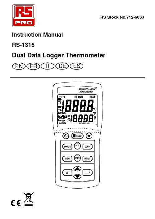
RS-1316Dual Data Logger ThermometerFREN IT DE ESTABLE OF CONTENTS/ENTABLE OF CONTENTSTITLE PAGE1. INTRODUCTION (1)2.SPECIFICATIONS (2)3. FRONT PANEL DESCRIPTION (4)4. OPERATION INSTRUCTIONS (7)5. MAINTENANCE (13)6. RECALIBRATION PROCEDURE (14)INTRODUCTION/EN1.INTRODUCTIONThis instrument is a digital thermometer for use with any J, K, T, E, N, R or S type thermocouple as a temperature sensor.Temperature indication follows the international temperature scale of 1990. (ITS-90)Read the following information carefully before attempting to operate or service the meter. When servicing, use only specified replacement parts.Environment conditionsAltitude up to 2000 metersRelative humidity: 80% max.Operating ambient temperature: 0 to 50°C (32 to 122°F) U.S. Pat. No. 446,135Safety symbolsComplies with EMC Directive 89/336/EECSPECIFICATIONS / EN2.SPECIFICATIONS2-1 Electrical specificationsMeasurement range:J - type: -150.0 to +1090.0°C (-200.0 to +1994.0°F)K - type: -150.0 to +1370.0°C (-200.0 to +1999.9°F)T - type: -150.0 to +400.0°C (-200.0 to +752.0°F)E - type: -150.0 to +870.0°C (-200.0 to +1598.0°F)N - type: -150.0 to +1300.0°C (-200.0 to +1999.9°F)R - type: 2.0 to +1767.0°C (+35 to +1999.9°F)S - type: 2.0 to +1767.0°C (+35 to +1999.9°F)Display effective resolution:J, K, T, E and N type: 0.1°C /°F /KR and S type: 1.0°C/°F /K (0.1°C/°F /K only for reference)Measurement accuracy:J, K, T, E and N type: ±[0.05% of reading +0.5°C (0.9°F)] [Below -100°C (-148°F): add 0.15% of reading for J, K, E and N; and 0.45% of reading for T]R and S type: ±[0.05% of reading +2°C (4°F)]NOTEThis basic accuracy specification does not include theerror of the temperature probe. Please refer to thetemperature probe accuracy specification for additionaldetails.SPECIFICATIONS / EN Temperature coefficient:0.01% of reading +0.03°C per °C (0.06°F per °F)Outside the specified +18°C to 28°C (+64°F to 82°F) range;[Below -100°C (-148°F): add 0.04% of reading for J, K, Eand N type and 0.08% of reading for T type]Maximum differential common-mode voltage: 1V(Maximum voltage difference between T1 and T2).Input protection: 20V maximum input voltage on anycombination of input connectors.Manual data-memory capacity: 98 sets.Continuity data-logging capacity: 4100 sets.2-2 General specificationsPower supply: Qty. 6 AAA batteries.Battery life: approx. 80 hours.Low battery indication: The symbol is displayed Measurement rate: Once per 1.5 seconds.Weight: 235 gms (8.29 oz)Dimension: 150x72x35 mmOperating temperature: 0 to 50°C (32 to 122°F)Operating Humidity: Below 80% RHStorage temperature: -10 to 60°C, 14 to 140°FStorage humidity: Below 70% RHSupplied accessories: Qty. 6 AAA Batteries, instructionmanual, CD software, and Optical RS-232 to USB cable.FRONT PANEL DESCRIPTION / EN3.FRONT PANEL DESCRIPTIONFRONT PANEL DESCRIPTION / EN(1). LCD display:A.Main display: T1, T2 or T1-T2 reading.B.Secondary display: T1 or T2 reading and MAX, MIN,AVG reading.C.Time display: Time display (100-hour clock) shows elapsedtime when MAX, MIN or AVG is on.D.Auto power-off mark (:).(2). H HOLD key: Press H HOLD key to freeze orunfreeze the display reading.(3). Power key: Press key to turn the meter on or off.(4). MX/MN key:Press "MX/MN" key to step through the maximum, minimum and average readings.Press "MX/MN" key for 2 seconds to exit MX/MN mode.(5). T1/T2/T1-T2 key:Press T1/T2/T1-T2 key to togglebetween T1, T2 or T1-T2 in themain or secondary display.(6). MEM key:Press the "MEM" key once to store a single set of logged data in memory.Press the "MEM" key for 2 seconds to enter continuous data-logging mode. Press again to exit this mode. (7). SET key:Press the "SET" key for 2 seconds thenrelease it to enter to interval time setting forcontinuous data-logging mode.FRONT PANEL DESCRIPTION / EN(8). Key:Press or key to increase or decrease the data-logging interval time setting.Press or key to increase or decrease the READ mode memory location.(9). ↵ key:Press "↵ " key to store interval time setting.Press "↵" key to toggle between the "hour:min" and "min:sec" elapsed time in the MX/MN mode.(10). TYPE key: Press "TYPE" key to select the thermocoupletype (K, J, E, T, R, S or N).(11). READ key:Press "READ" key to show manualmemory logged readings. Press againto exit this mode.(12). C/F/K key: Press C/F/K key to select Celsius (°C),Fahrenheit (°F) or Kelvin (K) temperaturescale.(13). key:Press backlight key to turn the backlight onand off. The backlight turns off after 13seconds automatically.(14). T1 input: Thermocouple T1 input.(15). T2 input: Thermocouple T2 input.(16). RS232 to USB optical interface jack.OPERATION INSTRUCTIONS / EN4.OPERATION INSTRUCTIONSWARNINGTo avoid electrical shock or personal injury, do not apply more than 20Vrms, between the thermocouples (s), orbetween any thermocouple and earth ground.If voltage on the measurement surfaces result in potentials more than 1V between the two thermocouples,then measurement errors may occur.If the potential differences are anticipated between thethermocouples, use electrically insulated thermocouples.4-1 Temperature measurementPress " " key to turn on the thermometer.Plug the thermocouple (s) into the thermocouple input(s) as required. If no thermocouple is plugged into the selected input or the thermocouple is "open circuit", the appropriate display will show "- - - -.-".Press the "C/F/K" key to select the desired temperature scale.Press "TYPE" key to select the thermocouple type required.Press "T1/T2/T1-T2" key to determine which of the T1, T2, and T1-T2 reading appear in the main display or secondary display.To measure the temperature, touch the probe sensor on the object whose temperature is to be measured.Read the temperature on the display. The display shows "OL" (overload) when the temperature being measured isoutside the valid measurement range of the meter.OPERATION INSTRUCTIONS / EN4-2 MAX, MIN and AVG operationPress "MX/MN" key to enter to MX/MN mode and to step through the maximum (MAX), minimum (MIN) or the true average (AVG is a true 9.7 hours recording average) mode.The auto power-off function will be automatically disabled.Press "↵" key for 2 seconds to toggle the elapsed time display between "hour:min" and "min:sec" on the LCD display.The elapsed time since entering reading mode, or the time at which the MAX, MIN or AVG value occurred will appear on the time display.Press "T1/T2/T1-T2" key to toggle between present reading of the T1, T2 and T1-T2 on the main display.Press "MX/MN" key and the MAX, MIN and AVG readingof T1/T2/T1-T2 will appear on the secondary display.T1 present reading + T1 Maximum reading plus elapsedtime + T1 Minimum reading plus elapsed time + T1Averaging reading plus averaging time.OPERATION INSTRUCTIONS / ENT2 present reading + T2 Maximum reading plus elapsed time + T2 Minimum reading plus elapsed time + T2Averaging reading plus averaging time.T1-T2 present reading + T1-T2 Maximum reading plus elapsed time + T1-T2 Minimum reading plus elapsed time +T1-T2 Averaging reading plus averaging time.Press "MX/MN" key for 2 seconds to exit MX/MN mode.In MX/MN mode, the "C/F/K" and "TYPE" keys are not active.OPERATION INSTRUCTIONS / EN4-3 To erase the memory of the DataloggerPress "Press and hold down the "MEM"key then press " " key turn onthe meter. The LCD display willshow "CLr" and all data stored inmemory will be cleared.Press the "MEM" key once andone set of readings will be storedin memory. The LCD displayshows " MEM " and a memorylocation number (01 to 98).Press "READ" key to enter themanual memory data mode. TheLCD display will show " READ "and a memory location number.Press " " or" "key to scroll through the logged readings.Press " READ" key again to exit READ mode.OPERATION INSTRUCTIONS / EN4-5 To Trigger continuous data-logging"To enter to logging interval time setting mode, press the "SET" key for 2 seconds then release it. The LCD display will show "INTERVAL", " MEM " and interval time.Press " " or" " key, until the display shows the required logging interval (3 to 255 seconds) and then press "↵"key to select.Press the "MEM" key for 2 seconds to start logging. The LCD display will show " MEM" and auto power-offfunction will be disabled. The " MEM " mark will flickereach time a set of data is stored into memory.OPERATION INSTRUCTIONS / ENWhen the memory is full (4100 data sets), the "FULL"symbol will appear on the display and the meter will stop datalogging.In the continuous data-logging mode, the MAX, MIN and AVG function can be used.Press the "MEM" again to stop logging. The continuously logged data can only be read after it is downloaded to aPC. It cannot be read using the "READ" function to showthe data the on display.4-6 How to disable auto power-off functionThe meter will automatically turn off if no key press occurs for 30 minutes.Press " " key to turn off the meter.Press and hold down the "↵ " key then press "turn on the meter and the auto power-off function will bedisabled.The time display auto power-off mark ":" will not be visible.Auto power off mode is enabled each time you turn on the meter. It is automatically disabled in "MX/MN" and continuous data logging modes.MAINTENANCE / EN5.MAINTENANCE5-1 Cleaning:Periodically cleans the case with a damp cloth and milddetergent.Do not use abrasives or solvents. Clean and dry asrequired.5-2 Battery Replacement:the batteries with Qty. 6 AAA cells.RECALIBRATION PROCEDURE / EN6.RECALIBRATION PROCEDUREThe thermometer should be calibrated once a year to ensure its continued accuracy. Contact RS Components for further details of calibration service. The address is given at the end of these instructions.。
干式变压器温度控制仪Temperature Controller for Dry-type Transformer安装使用说明书Installation Operation Instruction辽宁金立电力电器有限公司LIAO NING JIN LI ELECTRIC POWER EQUIPMENT CO.,LTDNO.1在使用您所购置的温控仪之前,请务必仔细阅读我公司的使用说明书。
并妥善保管,以备使用中查阅。
By all means please carefully read the operation instruction of our company before using the temperature controller. And please keep it safely for reference.注意事项 Note☆ 本说明书由最终使用者保留!☆ The manual should be kept by the end users!☆ 安装操作前,请认真阅读本手册!☆ Please carefully read the manual before installation and operation!☆ ※在进行变压器耐压试验前应先将传感电缆插头与温控仪分离,以免损坏温控仪!!!☆ ※Separate the sensor cable plug and temperature controller before havingwithstand voltage test of transformer in order to avoid damage☆ 为让温控仪能够长时间稳定运行,在搬运、安装时尽可能小心轻放。
☆ Please be careful as much as possible when handling and installing in order that the temperature controller can have a long and stable operation.☆ 请勿将温控仪安装在高温、强腐蚀性、高场强的环境当中。
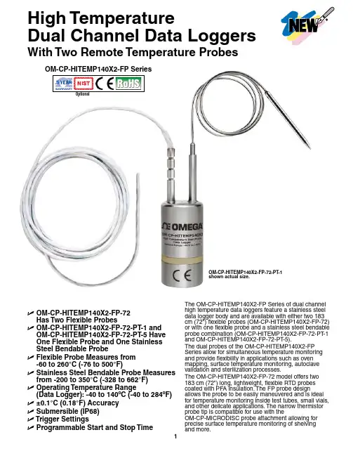
High TemperatureDual Channel Data Loggers With Two Remote Temperature ProbesOptionalU O M-CP-HITEMP140X2-FP-72Has Two Flexible ProbesU O M-CP-HITEMP140X2-FP-72-PT-1 and OM-CP-HITEMP140X2-FP-72-PT-5 HaveOne Flexible Probe and One StainlessSteel Bendable ProbeU F lexible Probe Measures from-60 to 260°C (-76 to 500°F)U S tainless Steel Bendable Probe Measures from -200 to 350°C (-328 to 662°F)U O perating Temperature Range(Data Logger): -40 to 140ºC (-40 to 284ºF) U±0.1°C (0.18°F) AccuracyU S ubmersible (IP68)U T rigger SettingsU P rogrammable Start and Stop Time The OM-CP-HITEMP140X2-FP Series of dual channel high temperature data loggers feature a stainless steel data logger body and are available with either two 183 cm (72") flexible probes (OM-CP-HITEMP140X2-FP-72) or with one flexible probe and a stainless steel bendable probe combination (OM-CP-HITEMP140X2-FP-72-PT-1 and OM-CP-HITEMP140X2-FP-72-PT-5).The dual probes of the OM-CP-HITEMP140X2-FP Series allow for simultaneous temperature monitoring and provide flexibility in applications such as oven mapping, surface temperature monitoring, autoclave validation and sterilization processes.The OM-CP-HITEMP140X2-FP-72 model offers two 183 cm (72") long, lightweight, flexible RTD probes coated with PFA insulation. The FP probe design allows the probe to be easily maneuvered and is ideal for temperature monitoring inside test tubes, small vials, and other delicate applications. The narrow thermistor probe tip is compatible for use with theOM-CP-MICRODISC probe attachment allowing for precise surface temperature monitoring of shelvingOM-CP-HITEMP140X2-FP-72-PT-1shown actual size.The OM-CP-HITEMP140X2-FP-72-PT-1 andOM-CP-HITEMP140X2-FP-72-PT-5 models feature a 61 cm (24") stainless steel bendable probe with the option of either a 2.5 cm (1") or 12.7 cm (5") probe tip (sheath). The stainless steel probe can be bent, angled, and coiled in any direction and formed into position as needed. The sharp probe tip allows for easy insertion and has an extended measurement range of-200 to 350°C (-328 to 662°F).The body of the OM-CP-HITEMP140X2-FP data loggers are capable of operating in temperatures from -40 to 140°C (-40 to 284°F). All models have the capacity to store up to 32,700 time and date stamped readings and feature non-volatile solid state memory that will retain data even if the battery becomesdischarged.The OM-CP-HITEMP140X2-FP utilizes the latest software. The device can be started, stopped, and data can be downloaded quickly and easily. Once in the software, the data can be reviewed in graphic, tabular, or summary form as well as exported to Excel® for further analysis and calculations.The OM-CP-MULTIMOUNTis a versatile mount orstand for use with theOM-CP-HITEMP140 series ofdata loggers. It can be usedto stabilize a logger inside anautoclave, or screwed to aflat surface to create ananchored base. Made of316 stainless steel, theOM-CP-MULTIMOUNTis able to withstandtemperatures up to150°C (302°F) making it ideal for use in autoclavesterilization processes.All modelsshown smallerthan actual size.OM-CP-HITEMP140X2-FP-72OM-CP-HITEMP140X2-FP-72-PT-5OM-CP-IFC400, Windows® software displays datain graphical or tabular format.SPECIFICATIONSTEMPERATURETemperature Sensor:OM-C -HITEM 140X2-F : Flexible RTD probe O M-CP -HITEMP 140X2-FP -P T: Flexible RTD Probe and bendable RTD probeProbe Measurement Range:Flexible Probe: -60 to 260°C (-76 to 500°F) Bendable Probe: -200 to 350°C (-328 to 662°F)Temperature Resolution: 0.01°C (0.02°F)Calibrated Accuracy: ±0.1°C (±0.18°F)GENERALReading Rate: 1 reading every second up to 1 reading every 24 hoursMemory: 32,767 readings Start Modes:• Software programmable immediate start • Delay start up to 18 months in advanceStop Modes: Manual or Timed (specific date and time)Real Time Recording: May be used with PC to monitor and record data in real timePassword Protection: An optional password may beprogrammed into the device to restrict access to configuration options. Data may be read out without the password Readings in Trigger Settings Mode: 16,383 readingsTrigger Settings: High and Low limits may be set. Once data meets or exceed set limits, the device will record to memory. Bi-level start and stop triggers can also be programmed. Users can specify the number of readings to take after the device triggers. (T riggering on channel 1 only)Memory Wrap Around: Y es (software selectable)Battery Type: 3.6V high-temperature lithium battery included; user replaceableBattery Life: 1 year typical [1 minute reading rate at 25°C (77°F)]Calibration: Digital calibration through softwareOM-CP-IFC406 multiplexer data logger interface, shown smaller than actual size (data loggers sold separately).Calibration Date: Automatically recorded within device Data Format: Date and time stamped °C, °F , °R, K Time Accuracy: 1 minute/month @ 25°C (77°F) • 1 minute/month at 25°C (77°F)Computer Interface: OM-CP-IFC400 USB docking station or OM-CP-IFC406 multiplexer interface required; 125,000 baudSoftware: Windows XP SP3/Vista/7 and 8 (32- and 64-bit)Operating Environment: -40 to 140°C (-40 to 284°F), 0 to 100% RH, 0.002 to 100 psia IP Rating: IP68Dimensions (Body): 48 H x 24.6 mm dia (1.89 x 0.97")Dimensions (Probe):OM-C -HITEM 140X2-F -72: Flexible robe: 1829 L x 2.5 mm dia (72 x 0.1") OM-CP-HITEMP140X2-FP-72-PT -1 with 2.5 cm (1") Bendable robe: robe Tip: 42 L x 3.2 mm dia (1.7 x 0.125") Bendable ortion: 559 L x 1.6 mm dia (22 x 0.062") OM-CP-HITEMP140X2-FP-72-PT -5 with 12.7 cm (5") Bendable robe: robe Tip: 121 L x 3.2 mm dia (4.8 x 0.125") with25 L x 4.8 mm dia (1 x 0.188") handle Bendable ortion: 559 L x 1.6 mm dia (22 x 0.062")Weight:OM-C -HITEM 140X2-F -72: 115 g (4.1 oz) OM-C -HITEM 140X2-F -72-T: 110 g (3.9 oz)Materials: Body: 316 stainless steel, PEEK Bendable Probe: 316 stainless steel Flexible Probe: PFA insulated cableOM-CP-MICRODISC surface temperature probe attachment (shown with probepackage and OM-CP-IFC406 multiplexer. OM-CP-IFC400 required for data logger operation. Both models sold separately.Ordering Example: OM-CP-HITEMP140X2-FP-72-CERT high temperature data logger with two 183 cm (72") flexible probes and NIST calibration certificate.To OrderModel No.DescriptionOM-CP-HITEMP140X2-FP-72-PT -5 shown smaller than actual size.。
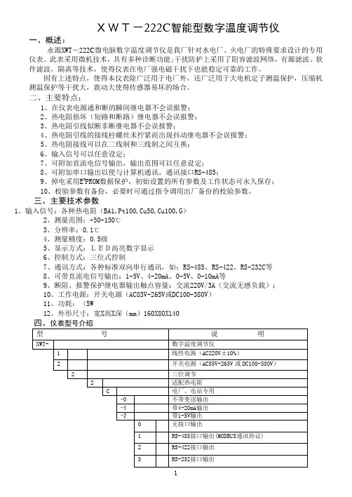
XWT-222C智能型数字温度调节仪一、概述:永源XWT-222C微电脑数字温度调节仪是我厂针对水电厂、火电厂的特殊要求设计的专用仪表。
此表采用微机技术,具有多种诊断功能;干扰防护上采用了阻容滤波网络,有源滤波、软件滤波,隔离等技术,使得仪表在电厂强电磁干扰下也能稳定可靠的工作。
因有上述特点,使得本仪表除广泛用于电厂外,还广泛用于大电机定子测温保护,压缩机测温保护等干扰大,震动大使得传感器易坏的场合。
二、主要特点:1、在仪表电源通和断的瞬间继电器不会误报警;2、热电阻损坏(短路和断路)继电器不会误报警;3、热电阻引线似断非断继电器不会误报警;4、热电阻引线的接线柱螺丝未拧紧而出现抖动继电器不会误报警;5、热电阻接线可以在二线制和三线制之间互换;6、输入信号可以任意设定;7、可附加直流电信号输出,输出范围可以任意设定;8、可附加串口输出以便与计算机通讯,通讯接口RS-485;9、掉电采用E2PROM数据保护,初始设置的所有参数及工作状态可永久保存;10、校验参数有备份,必要时可通过指令调用出厂备份的校验参数。
三、主要技术参数1、输入信号:各种热电阻(BA1,Pt100,Cu50,Cu100,G)2、测量范围:-50-150℃3、分辨率:0.1℃4、测量精度:0.5级5、显示方式:LED高亮数字显示6、控制方式:三位式控制7、通讯方式:各种标准双向串行通讯,如:RS-485、RS-422、RS-232C等8、可带直流电信号输出:1-5V、4-20mA、0-5V、0-10mA等9、断阻、报警保护继电器输出触点容量:交流220V/3A(交流无感负载);10、工作电源:开关电源(AC85V-265V或DC100-380V)11、功耗:〈5W12、外形尺寸:宽X高X深(mm)160X80X140五、面板介绍〈图一> 面板布置图 键:参数设定选择键,按序变换参数设定模式。
键:参数变更时,增加数值,连续按压,将自动快速增“1键:参数变更时,减少数值, 连续按压,将自动快速减“1”。
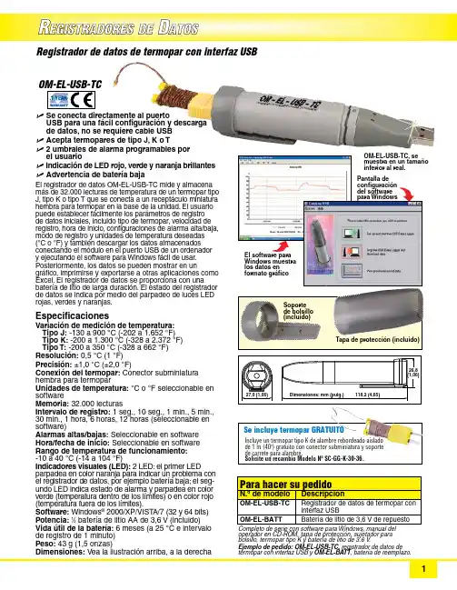
R EGISTRADORES DED ATOSU S e conecta directamente al puerto USB para una fácil configuración y descarga de datos, no se requiere cable USB U A cepta termopares de tipo J, K o T U 2 umbrales de alarma programables por el usuarioU I ndicación de LED rojo, verde y naranja brillantes U A dvertencia de batería bajaEl registrador de datos OM-EL-USB-TC mide y almacena más de 32.000 lecturas de temperatura de un termopar tipo J, tipo K o tipo T que se conecta a un receptáculo miniatura hembra para termopar en la base de la unidad. El usuario puede establecer fácilmente los parámetros de registro de datos iniciales, incluido tipo de termopar, velocidad de registro, hora de inicio, configuraciones de alarma alta/baja, modo de registro y unidades de temperatura deseadas(°C o °F) y también descargar los datos almacenados conectando el módulo en el puerto USB de un ordenador y ejecutando el software para Windows fácil de usar.Posteriormente, los datos se pueden mostrar en un gráfico, imprimirse y exportarse a otras aplicaciones como Excel. El registrador de datos se proporciona con una batería de litio de larga duración. El estado del registrador de datos se indica por medio del parpadeo de luces LED rojas, verdes y naranjas. Especificaciones Variación de medición de temperatura:T ipo J: -130 a 900 °C (-202 a 1.652 °F) Tipo K: -200 a 1.300 °C (-328 a 2.372 °F) Tipo T: -200 a 350 °C (-328 a 662 °F)Resolución: 0,5 °C (1 °F)Precisión: ±1,0 °C (±2,0 °F)Conexión del termopar: Conector subminiatura h embra para termopar Unidades de temperatura: °C o °F seleccionable en software Memoria: 32.000 lecturas Intervalo de registro: 1 seg., 10 seg., 1 min., 5 min., 30 min., 1 hora, 6 horas, 12 horas (seleccionable en software)Alarmas altas/bajas: Seleccionable en software Hora/fecha de inicio: Seleccionable en software Rango de temperatura de funcionamiento: -10 a 40 °C (-14 a 104 °F)Indicadores visuales (LED): 2 LED: el primer LED parpadea en color naranja para indicar un problema con el registrador de datos, por ejemplo batería baja; el seg-undo LED indica estado de alarma y parpadea en color verde (temperatura dentro de los límites) o en color rojo (temperatura fuera de los límites).Software: Windows ® 2000/XP/VIST A/7 (32 y 64 bits)Potencia: 1⁄2 batería de litio AA de 3,6 V (incluido)Vida útil de la batería: 6 meses (a 25 °C e intervalo de registro de 1 minuto)Peso: 43 g (1,5 onzas)Dimensiones: Vea la ilustración arriba, a la derecha Registrador de datos de termopar con interfaz USB configuración del software para Windows Soporte de bolsillo (incluido)Tapa de protección (incluido)operador en CD-ROM, tapa de protección, sujetador para bolsillo, termopar tipo K y batería de litio de 3,6 V .Ejemplo de pedido: OM-EL-USB-TC, registrador de datos de termopar con interfaz USB y OM-EL-BATT , batería de reemplazo.Incluye un termopar tipo K de alambre rebordeado aislado de 1 m (40") gratuito con conector subminiatura y soporte de carrete para alambre. Solicite un recambio Modelo Nº SC-GG-K-30-36.Se incluye termopar GRATUITO。
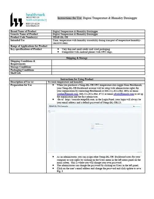
Instructions for Use: Digital Temperature & Humidity DataloggerTo track temperature and humidity.●When you purchase a Temp-DL-TH NFC temperature data logger from Healthmark,your Temp-DL-TH Dashboard account will be setup with administrator rights foryour organization by contacting Healthmark at 800-521-6224 Ext. 6634 or email****************, 800-521-6224 Ext. 6722 or email **************** to set up the organization and the first admin/user.● Go to: https://. in the Login Panel, your login will always beyour email address and a default password of Temp-DL-TH123.●As an administrator, you can assign other Temp-DL-TH Dashboard users for yourcompany or user rights by clicking on the Users menu in the left menu panel on themain screen. This is where you will change your own password.●The administrator can change the password by clicking on Users in the left panel.●Click on the user’s email address and change the password and click update to save.Fig. 1Figure 1●If you change your password in Temp-DL-TH Dashboard, remember to change it inTemp-DL-TH NFC.Setup Temp-DL-TH Console ConnectionIf you are using Android NFC Smartphone or Tablet1. Tap on the Apps icon, tap on the Play Store app.2. At the top of the page where it says ‘Google Play’ on your Android NFC enabledsmartphone or tablet, type in “healthmark”.3. Scroll down the list of apps to ‘TEMP-DL-TH app and tap to download app onto thesmartphone or tablet.4. After the installation is complete, the TEMP-DL-TH app will appear on the phone ortablet screen.●Tap the Temp-DL-TH NFC logger with your smartphone or tablet to open up theApp. (Fig.1) Place your smartphone next to the datalogger.●Tap on the ⁝ icon (top right corner) to select the WiFi Settings menu. (Fig. 2.)●Tap on ⁝ icon and select settings i n the menu. (Fig. 3.)●Enter your Temp-DL-TH Dashboard login email address and password. (Fig. 4.)Figure 1 Figure 2Figure 3 Figure 4Using and reading a Temp-DL-TH NFC Temperature Data LoggerFigure 1 Figure 2Figure 3 Figure 4Figure 5 Figure 6 Reading a NFC Temperature Data Logger with a NFC Mobile Device1.Bring the mobile NFC device to the Temp-DL-TH NFC logger about 1” away. When Temp-DL-TH “Temp” start screen shows, move mobile device away an d bring back to mobile device. (Fig. 1)2. Make sure Temp-DL-TH NFC mobile App is setup with your Temp-DL-TH Dashboard login and preferences are set in the App Settings screen. (Fig. 2)3. If Auto PDF Report Download is not set, you will be prompted if you want to download the temperature PDF report to your mobile device. (Fig. 3)●Log onto .●In the measurement screen, click on the chart button.●In the strip chart screen, set the date and time range and click on the PDF button.●The PDF temperature report is instantly created.4. To view recording details, tap on the Recording Details button. (Fig. 4)5. To view the temperature chart, tap on the Temperature Graph button or see other functions. (Fig. 5)6. View temperature chart, download PDF report, or upload data to Temp-DL-TH Dashboard on the cloud. (Fig. 6)Figure 1 Figure 2Figure 3 Figure 4 Figure 5Figure 6Build Custom Profiles On Your Temp-DL-TH NFC Temperature Data Logger1. Bring Temp-DL-TH mobile NFC device to the Temp DL-TH NFC logger about 1” away, Temp-DL-TH “Temp” start screen shows, move the mobile device away and bring back to mobile device. (Fig.1)2. Tap the first wrench tool in the top status bar. (Fig. 2)3. Default Profile window will display. Tap on the symbol with the plus sign and circle around it in the top status bar to customize a profile. (Fig.3)4. Tap on the plus sign and circle around it in the top right corner. Give the profile a unique name. (Fig. 4)5. The custom profile screen will be blank. Tap on the symbol with the plus sign and circle around it above the pencil icon in the blue menu bar to add a field to the profile. (Fig. 5)6. Arrow back to Profile Manager and select Predefined Field and enter the attribute value such as text for description, integer value for temperature or search time limits, and Cancel or OK for check box. Or enter your own custom text field and data. (Fig. 6)7. Once all the fields are defined, tap on the Save icon to save the custom profile. (Fig.7)Figure 1 Figure 2 Figure 3Figure 4 Figure 5 Figure 6 Figure 7Rev. B。
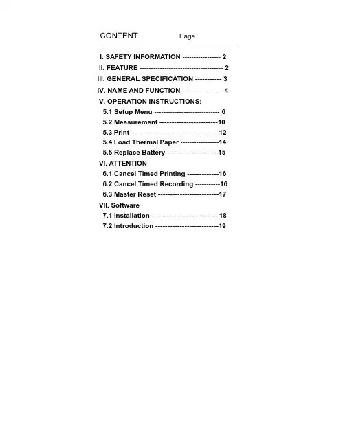
CONTENT PageI. SAFETY INFORMATION ----------------- 2 II. FEATURE ------------------------------------- 2 III. GENERAL SPECIFICATION -----------3 IV. NAME AND FUNCTION ------------------ 4 V. OPERATION INSTRUCTIONS:5.1 Setup Menu-----------------------------6 5.2 Measurement ------------------------10 5.3 Print ---------------------------------------12 5.4 Load Thermal Paper -----------------14 5.5 Replace Battery ---------------------15 VI. ATTENTION6.1 Cancel Timed Printing -------------16 6.2 Cancel Timed Recording -----------16 6.3 Master Reset -------------------------17 VII. Software7.1 Installation ---------------------------18 7.2 Introduction --------------------------19servicing not covered in this manual.3. Periodically wipe the case with a dry cloth. Do not use2. Text Print Out.3. The easy access menu buttons and text area in the LCDdisplay provide a simple and intuitive hierarchical menu operation for system setup.4. Built in system clock.5. Photo coupler isolated RS-232 interface.6. With Windows software.7. 32,000 Records Data Logger.8. T1 & T2 dual display with swapping display area.9. MAX / MIN function.10. REL function.2I. GENERAL SPECIFICATION1. Measurement Range: TYPE K -200¡C ~ 1370¡C -328¡F ~ 2498¡F TYPE J -200¡C ~ 760¡C -328¡F ~1400¡F2. Accuracy: -200¡C ~ 1370¡C –0.1% + 0.8¡C-328¡F ~ 2498¡F –0.1% + 1.6¡F3. Resolution: 0.1¡C / 0.1¡F4. Sample Rate: 2 times / second5. Input Protection: 60V DC or 24Vrms AC6. Data Logger: 32,000 Records7. Storage Condition: -10¡C ~ 60¡C (14¡F ~ 140¡F)0 ~ 80% RH8. Operating Condition: 0¡C ~ 50¡C (32¡F ~ 122¡F)0 ~ 80% RH9. Battery: Size AA 1.5V x 6 (alkaline battery)10. AC Adapter: DC 9V ~ 12V , 1A Min11. Thermal Paper: 58mm width, 31_12. Dimension: 242 x 98 x 42mm13. Weight: 580g Approx.14. Accessory: Tool BoxAlkaline Battery Size AA 1.5V x 6Instruction MenuK Type Sensor x 2 (-50¡C ~ 200¡C)Thermal Paper x 2 (31_x 58mm)RS-232 Connection CableWindows Software Disk34V. NAME AND FUNCTIONDC 9VT2T1T2¢X F RELPRINTINST RECFEEDMINMAX C¢X C T1TEMPERATURE RECORDEROPENMENUCMENUINSTPRINTFEEDREC REL MAX MIN¢X C ¢X F T1T2Paper SoltPaper Output Manual Feed Knob Print Head LevelL C DDC 9V JackSetup Panel Function PanelPrint PanelTemperature Sensor Input ConnectorFunction Panel:Setup Panel:Print Panel:Exit without savingEnterBrowse menu or number down Browse menu or number up Paper feed 2/3 inchStart / Stop printingPrint present data Power button¢X C / ¢X F button Record buttonT1 / T2 button Relative readout button MAX / MIN button6V. OPERATION INSTRUCTIONS5.1 Setup MenuPress Menu select button to select menuCMENU MENUTEMPERATURE RECORDEROPENExit without savingEnterBrowse menu or number down Browse menu or number up7Menu itemMenu description Set system clock Set thermocouple typeNote: Thermocouple type must be the same as thetype of sensor.369875421Set system clock Set start/stop printing time and print mode Set Thermocouple Typerecord interval Set start/stop recording time and Clear Datalogger memory Power management setup Alarm limit setupPrinter test printingPrint out setup information1Set time Set date Set year2Select J TypeSelect K Type16VII. Software7.1 InstallationSystem Required:Windows 95 / Windows 98 / Windows MEWindows NT 4.0.Minimum Hardware Required:PC with Pentium 90MHz or higher.32 MB RAM.4X CD-ROM Drive or higher.Recommended resolution 800X600.At least 5 MB byte hard disk space available toinstall TestLink.Installation :1.We recommend close all other applicationbefore installing TestLink.2.Insert the setup CD disc to CD-ROM drive and theinstallation program should start automatically.3.If installation do not start automatically, choose thestart button on the Taskbar and select Run.4.Type E:\SETUP and choose OK, then it will copySE500.exe (executable file) and help file to yourhard disk (default is c:\programfiles\TestLink\SE500).1819.2 IntroductionMain ScreenMain menuTool menuReading display Real time graphReal time list Max/Min/Avgdisplay Main ScreenFile : Open - Open files saved previously from the disk. Save - Save the active window(when the caption baris highlighted) data to the disk. Print - Print the data of the active window(graph or list).Printer Setup - Select printer.Exit - Terminates TestLink program.DataLogger : By opening the D ataLogger Window,the user can load recorded data ofmeter to PC in this window.Real Time Data : Run - Start recording real time data.Stop - Stop recording real time data.Option : Setup Temperature Recorder from PC. COM port : Select PC connector port manually.View : LCD - Open LCD simulation window.Real Time Graph - Open Real-Time Graphwindow to graph the presentdata.Window : Arrange windows Help : On line help.20DataLoggerata Sets ListData ListWhen you have Temperature Recorder meter connected to PC and select "DataLogger" from main menu or click from tool bar to load recorded data from the meter and there will be a progress indicator to show the loading progress. If error occurs, just click "D ataLogger" again.After the data was loaded completely, the top left hand side will show how many data sets were loaded and detail information for each data set (start data, start time,recording rate and record numbers).For examples, the figure below means there are two data sets, set 1 recorded 1325 records and set 2 recorded 19349 records.It will transfer first data set to graph on the right hand side and list data after loading, You can click other data set to view the graph and list of the data set you select.Tutorial Quick StartRecording real time data from PC.1.Power on the Temperature Recorder first and connect it to a PC RS-232 serial port wit the cable,2.Run the Software.3.If the connection is successful the LCD simulation willdisplay the same value as the Temperature Recorder.If fail to connect the meter with PC, it will display "NoConnection" on the LCD simulation window .4.When the connection is successful, select Real TimeData | Run from main menu or click from tool bar,there will be a dialog for you to select record intervaland record numbers and click start button to startrecording.5. When the recorded data numbers reach to theamount you set, it will stop recording, or click to stoprecording .How to save the recorded real time data to a file ?1.Click the window you want to save and the windowwill become active , then choose File | Save frommain menu or click from the tool bar.2.There will be a save dialog window for you to choosethe file name and file type to save.3.There are three types of file name you can choose,they are binary file(*.ghf), text file(*.txt) and EXCELformat file(*.csv). The *.ghf file use much fewer diskspace to save the data than the other two file format,but it can only be used in TestLink SE500. Text filecan be opened by TestLink SE500 and any otherword processor program like word, notepad etc.EXCEL format file can b e opened by TestLink SE500and Microsoft EXCEL.21How to load the recorded data from the memoryofTemperature Recorder and save it to a file ?1. Power on the Temperature Recorder.2. Connect the Temperature Recorder to PC3. Start SE500 program.4. Choose Data Logger from main menu or clickfrom tool bar.5. In reference to Data Logger, see [Page 20] aboutDataLogger.For more operation instruction, please refer to theonline help while executing SE500.22。
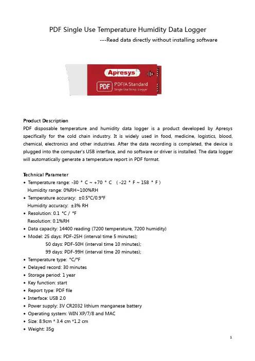
PDF Single Use Temperature Humidity Data Logger---Read data directly without installing softwareProduct DescriptionPDF disposable temperature and humidity data logger is a product developed by Apresys specifically for the cold chain industry.It is widely used in food,medicine,logistics,blood, chemical,electronics and other industries.After the data recording is completed,the device is plugged into the computer's USB interface,and no software or driver is installed.The data logger will automatically generate a temperature report in PDF format.Technical Parameter◆Temperature range:-30°C~+70°C(-22°F~158°F)Humidity range:0%RH~100%RH◆Temperature accuracy:±0.5°C/0.9°FHumidity accuracy:±3%RH◆Resolution:0.1°C/°FResolution:0.1%RH◆Data capacity:14400reading(7200temperature,7200humidity)◆Model:25days:PDF-25H(interval time5minutes);50days:PDF-50H(interval time10minutes);99days:PDF-99H(interval time20minutes);◆Temperature type:°C/°F◆Delayed record:30minutes◆Storage period:1year◆Key function:start◆Report type:PDF file◆Interface:USB2.0◆Power supply:3V CR2032lithium manganese battery◆Operating system:WIN XP/7/8and MAC◆Size:8.9cm*3.4cm*1.2cm◆Weight:35gOperational Instruction1.Press and hold the start button for about3seconds.The red indicator light flashes3times,then flashes10times quickly,indicating that the startup is complete.2.When the PDF data logger is inserted into the computer,a report in PDF format will be automatically generated.When the data logger is inserted into the computer,the data logger will stop working automatically.Operation InstructionNote:1.When placing the data logger in the test environment,make sure the data logger is in the startup or start delay state.2.When the data logger is plugged into the computer,if the indicator is not lit,check if the USB port is inserted in the opposite direction.3.Corrosive liquids can damage the equipment and cause it to malfunction.Avoid contact with corrosive objects.4.The device contains a CR2032non-rechargeable lithium battery.Do not put the device in a high temperature environment or charge it directly.5.For long-term effective use of the data logger,store it at room temperature and keep the data permanently.6.Please recycle and dispose of the equipment in accordance with local laws and regulations.StatusAction LED indication Before startingShort press button The indicator will light once StartLong press 3-5s The indicator flashes 3times then flashes 10times WorkingShort press button The light does not flash on working.Short press button,the indicator flashes 10times quickly StopShort press button Long light。
温度记录仪使用说明书一、产品概述温度记录仪具备性能可靠、操作简单、功耗低、断电后数据不丢失、防水性能好等特点,数据处理软件界面友好。
该系列产品广泛适用于食品、药品、冷链运输及各个要求符合HACCP 体系的行业,也可用于实验室等需要对温度作监控记录的场所。
二、技术参数1、供电电源:2.4Ah 3.6V 非充电电池一枚(当温度记录仪与计算机有效连接时,其电源由计算机通过USB接口供给)2、测温范围:传感器外置状况下:-40.0℃~70.0℃3、测温精度:-20℃~20℃时±0.5℃;其余范围内±1℃4、温度分辨率:0.1℃5、记录周期:2秒~24小时可连续设置.6、传感器类型:NTC7、实时传输时间间隔:10秒至24小时可调8、记录容量:16000点。
9、工作环境要求:温度-30℃~50℃;湿度15%~85%10、数据输出:通过USB接口与计算机交换数据11、防护等级:IP65三、液晶屏状态说明Busy:忙状态,仪表重启经过此状态后进入正常工作状态:上限报警状态,当温度大于上限值显示此报警状态:下限报警状态,当温度小于下限值显示此报警状态Wait:记录未启动状态,可持续按键5秒启动记录Record:处于记录状态End:记录停止状态Max:已记录数据的最大值Min:已记录数据的最小值Act:当前数据Log:历史数据(最大值、最小值、已记录容量)EE:传感器故障状态℃:温度单位:电池容量四、主要功能该仪表可对记录仪属性进行设置,包括用户信息、仪表站号、报警上下限参数;工作状态指示;单键操作,状态指示灯可指示各工作状态、可启动记录、可选择停止记录;符合HACCP的要求;温度传感器可内置亦可外置(出厂配置为外置传感器)。
可设置记录间隔、温度报警的上下限、记录仪时钟及记录仪和用户信息等属性,数据软件还具有数据分析的功能,可通过列表显示数据和绘制曲线分析图,对超温限报警点显示报警标志。
历史数据可以查询、保存、打印和以Word格式输出。
Instructions for Use: TCDL2: TempaChek-DL™Brand Name of Product TempaChek-DL™Generic Name of Product TempaChek-DLProduct Code Number(s)TCDL2Purpose of Product The TempaChek-DL™ is a thermologger capable of measuring the water temperaturethrough the cycle.Range of Applications for Product To track temperature in a specific environment.Key Specifications of Product∙TempaChek-DL™ is a data logger that measures and stores up to 32,510 temperaturereadings over a -40 to +125°C (-40°F to +257°F) range.∙You can easily set up the logging rate and start-time, and download the stored databy plugging the data logger into a PC's USB port and running the purpose designedsoftware under Windows 2000, XP (Home and Professional Editions), Vista and 7.Logged data can then be graphed, printed and exported to other applications such asspreadsheets and reports.∙The data logger is supplied complete with a long-life, replaceable lithium battery,which can typically allow logging for two years.∙The data logger is protected against moisture to IP 67 standard using two o-rings.123456789 1012 131415 161718 192020aSteps for Use of Product 1.Insert software flash drive into USB port on your computer.2.Select “Open folder to view files”.3.Next select folder “Temp-DL”.4.Then select the icon that reads, “Set up Temp DL”.5.Install window will be prompt open, click “Install”.6.Then click “Next”.7.When installation is finished, select “Finished” when window is prompted open.8.Unscrew cap of the TempaChek-DL™ Datalogger.9.Insert the TempaChek-DL into a free USB port on your computer.10.The computer will automatically detect the presence of the TempaChek-DL™ andstart the hardware installation process.11.Double-click the EasyLog USB icon on your desktop to launch the control software.You will be presented with three options on the Main Screen.12.Click on the green button to set up and start the TempaChek-DL™ Data Logger andfollow the setup procedure:B Data Logger Name, Temperature Scale and Sample Rate: - enter the LoggerName, - select the Temperature Scale, - select the Sample Rate, - then click “Next”.a.Note: If you are using this Data Logger for the first time, then it maycontain some sample data, in which case you will receive a warningmessage. Click “OK” to continue.14.Logger Options: - select whether the logger should stop saving data when full orbegin overwriting the oldest data. Then click “Next”.15.Setting alarm levels for the USB Data Logger: - select the Alarms, if required, -select the Alarm Trigger Levels for any selected alarms, - select Hold for anyselected alarms, - then click “Next”.16.Setting the start time and date: - either click Finish if you want to start loggingimmediately or - select the Start Time and Start Date for logging to commence, andthen click “Finish”. The summary screen will now appear.17.Remove the TempaChek-DL™ from the computer and place it in the location whereyou want to measure temperature.a.Note: If you leave the TempaChek-DL™ connected to your PC, the DataLogger will operate at an elevated temperature, due to a self-heating effect.This will cause the Data Logger to record erroneous temperature readings.If the Data Logger is connected to the USB port for a long time (e.g. 15minutes), then you should allow time for the Data Logger to cool down afterdisconnecting it from the USB port.18.Click on the “red” button to stop the datalogger and download and stored data.a.You will be asked to confirm that you wish to stop the USB Data logger,click “yes”.19.A window will pop up to show that the Data Logger has stopped. It will also displaythe name and amount of readings stored.20.Save the file under a suitable file name.a.The data will remain in the logger’s memory until it has been set up again. Interpretation of ResultsContraindications of Test ResultsDocumentationSpecial Warnings and Cautions∙When the TempaChek-DL™ is connected to the USB port, the battery inside theData Logger is discharged at a higher rate than normal. To conserve battery life, donot leave the TempaChek-DL™ connected to the USB port for a prolonged period oftime.∙The TempaChek-DL™ is a professional measuring instrument, designed to recordTEMPERATURE. Care must be taken when:o 1. Removing the logger from extreme environment- The logger is metal andwill retain heat or will remain cold when it has been removed from theenvironment under measurement. Personal protection, such as suitable heatresistant gloves or tools must be used to remove the logger from anyenvironment. See data sheet for maximum and minimum temperatures thatthe logger can be used in.o 2. Replacing batteries- Always operate TempaChek-DL™ and replace itsbatteries according to the instructions.∙The TempaChek-DL™ will work in extreme temperatures. However, many batterieswill not work at these extremes. Always ensure the specific battery as detailed byHealthmark is used. Serious injury can occur if the incorrect battery is used.∙TempaChek-DL™ is not authorized for use as a critical component in life supportdevices or systems.DisposalRelated Healthmark ProductsOther Product Support Documents For more information go to “Help” file contents on the software installation flash drive. Reference Documents ProFormance™ Brochure, ProFormance™ Price ListCustomer Service Contact Healthmark Industries Company, Inc.18600 Malyn Blvd.Fraser, MI 480261-586-774-7600********************。
S-XTemperature Chart RecorderU A dvancedMicrocontroller Design U L arge LED Digital Temperature Display U 3 Temperature Ranges and 4 Chart Speeds U F ront Panel Selectable Single Turn or ContinuousChart Rotation U F ront Panel Controls for Fast and Easy Setup U S tandard 120V Operation U B attery Back-Up Assures Normal Operation During Power Interruptions U 12V Vehicular or Marine Use Operations U S tainless Steel Remote Reading 102 mm (4") Probe with 4.6 m (15') Cable U Fold-Down Handle U F reestanding or Wall Mounted U D urable Polycarbonate Case, Cover, and Handle Applications U F ood Storage U E nvironment, Energy Management U H VAC, Refrigeration Maintenance U G eneral Laboratory Monitoring U C omputer RoomM onitoring U O vens, Dryers, Paint BoothsThe newly designed CT89temperature recorder with remote sensor employs advanced microcontroller design thatenables this versatile instrument to accurately measure and record temperatures in air, gas, liquids, powders, solids, and semi-solids. The CT89 is a precision instrument used to monitor and recordtemperature on 6" circular chartpaper. It may be carried as aportable instrument or mounted in a fixed location. A combination of 3 temperature ranges and 4 chart speeds provide a high degree of flexibility. In addition, the chart rotation may be set for single or continuous turn operation. Toprotect the data being recorded the CT89 uses an automatic battery backup to maintain operation during a power outage.CT89F with probe included.S-YOMEGACARE SM extended warranty program is available for models shown on this page. Ask your sales representative for full details when placing an order. OMEGACARE SM covers parts, labor and equivalentloaners.Comes complete with 60 assorted 152 mm (6") diameter charts, 102 mm (4") probe, 2 black cartridge pens, and operator’s manual.* Insert “6H” for 6-hour, “24H” for 24-hour chart, “7D” for 7 days, or “31D” for 31 days.** Insert either “F” or “C” for an assortment of 60 charts.Ordering Example: CT89F, temperature chart recorder 110 Vac.OCW-3, OMEGACARE extends standard 1-year warranty to a total of 4 years.SpecificationsTemperature Scale: -40 to 30°F, -20 to 50°F, 50 to 120°F, -40 to 0°C, -30 to 10°C, and 10 to 50°CChart Speed Selectable: 6 hours, 24 hours, 7 days, 31 days Chart Speed Accuracy: ±1%Chart Diameter: 152 mm (6")Temperature Display: 3 digit LED; 13 mm (0.5") HTemperature Accuracy: ±1°C (±2°F)Temperature Sensor: Stainless steel tip submersible with 4.6 m (15') of cable Recording Pen: Ink typePower Supply: 120 Vac, 50/60 Hz or 220/240 Vac, 50 HzBattery Backup: 8 alkaline “AA” cells (included)Battery Life: 48 hoursOperating Temperature: 0 to 49°C (32 to 120°F)Operating Humidity: 0 to 96% maxDimensions: 235 L x 184 W x 70 mm D (9.25 x 7.25 x 2.75")Weight: 7 oz (4 lb)CT89F.。
CT87LF low temperature recorder, with CT87-J-NP probe (included with the CT87L models).Circular Chart Recorder U E asy-to-Read 152 mm (6") Circular ChartU Type J Thermocouple Input U Economical U L ED Digital Display of Temperature U F ront Panel Controls for Fast, Easy Setup U S elect From 3 Temperature Ranges U 6-Hour, 24-Hour, or 7 Day Chart Rotation U S elect for Single or Continuous Chart Rotation U F ree Standing or Wall MountedU Fold Down Carrying Handle U Durable Polycarbonate Case U P lug-In SMP Connection for J Thermocouple U A daptor for 120 Vac Operation (220 Vac Optional)U B attery Back-Up for Power Interruptions CT87LF or CT87LC U L ow Temperature Recorders U T ypical Temperature Measurement Applications U FreezersU Refrigerators U Environmental U ChambersU Room Temperatures CT87LC Ranges U -40 to 0°C, -30 to 10°C, and 10 to 50°C CT87LF Ranges U -40 to 30°F, -20 to 50°F, and 50 to 120°F U C omes with 4" L, 1⁄8" Dia., 304 SS Needle Tip Probe with 4.6 m (15') Leads CT87HF or CT87HC U H igh Temperature Recorders for Higher Temperature Measurement Applications U Ovens U Process Chambers CT87HC Ranges U 0 to 120°C, 0 to 250°C, and 250 to 500°C CT87HF Ranges U 0 to 250°F, 0 to 500°F, and 500 to 1000°F U C omes with 6' L 24 Gage Glass Insulated ThermocoupleThe CT87 Series temperature recorder is a precision instrument used to monitor and record temperature on a 152 mm (6") circular chart. The CT87 may be carried as as portable instrument or mounted in a fixed location. The CT87 offers a variety of features to meet any temperature recording requirement. A combination of 3 temperature ranges and 3 chart speeds provides a high degree of flexibility. In addition, the chart rotation may be set for single or continuous turn operation as required by a particular application. To protect the data being recorded, the CT87 uses an automatic battery backup to maintain operation during a power outage.Comes complete with 1 package assorted charts, 2 pens, AC adaptor, Type J thermocouple, 8 “AA” batteries and operator’s manual. CT87L also comes with CT87-J-NP probe. CT87H also comes with TC-GG-J-24-72-SMP-M beaded wire thermocouple probe.Ordering Examples: CT87HC, 110V circular chart recorder with beaded wire probe included.OCW-3, OMEGACARE SM extends standard 1-year warranty to a total of 4 years.for 7 days.** Insert either F or C for an assortment of 60 charts.SpecificationsTemperature Scale Selectable: Low Temp°F: -40 to 30, -20 to 50, 50 to 120 Low Temp °C: -40 to 0, -30 to 10, 10 to 50 High Temp °F: 0 to 250, 0 to 500, 500 to 1000 High Temp °C: 0 to 120, 0 to 250, 250 to 500Ambient Operating Temp: 0 to 49°C (32 to 120°F)Relative Humidity: 0 to 96%Accuracy: ±1°C (±2°F)Chart Diameter: 152 mm (6")Chart Speed Selectable: 6-hr, 24-hr, 7 daysChart Rotation Selectable: Single turn, continuousChart Speed Accuracy: ±1%Display: 3 digit LED 13 mm (0.5")Recording Pen: Ink typeCase Size: 235 H x 184 W x 70 mm L (91⁄4 x 71⁄4 x 23⁄4" )Weight: 2.2 kg (4 lb, 7 oz)Battery Back-Up Life: 48-hr, 8 “AA” alkaline batteries (included)Primary Power: 115 Vac, 50/60 Hz or 220 Vac, 50/60 HzTemperature Probe: Low Temp Recorder: CT87-J-NP (needle probe) High Temp Recorder: TC-GG-J-24-72-SMP-M-PP CT87LF low temperature model, with CT87-J-NP probe (included with the CT87L models), shown smaller than actual size.OMEGACARE SM extended warranty program is available for models shown on this page. OMEGACARE SM covers parts, labor, and equivalent loaners. Ask your sales representative for full details when placing an order.。
SPECIFICATIONTemperature Stability:50 ppm/°C Display:4-digit, 7-segment LED,101.6mm (4.00”) with red, green and amber programmable colors.Alarm:Alarm 1 & 2 programmable, Latch/Unlatch, High, Low, High/LowSERIAL INTERFACECommunication Standard:RS-485, RS-422 or RS-232Transfer speed (Baud rate):300, 600, 1200, 2400, 4800, 9600,19200 bps Data Format:7O1-7 bit, Odd,1stop bit,7E1- 7 bit,even, 1 stop bit8N1 – 8 bit, No parity, 1 stop bit Multi-Point Address (RS-485):0 to 199Flow Control:No Flow controlScrew terminals forRS-232/485/422 interface Power Supply:100-240 Vac ±10%,50/60 Hz, 22.5 WOperating Temperature:0 to 40°CStorage Temperature:-20 to 60°CRelative Humidity:0 to 85%Protection:NEMA-4x (IP65)Dimensions:480.0L x 210.8W x 95.4D mm (18.11" x 8.31" x 3.76")Panel Cutout:414.3 L x 179.4 W mm (16.31” L x 7.06” W)Weight:2,495 g (5.5 lbs)Approvals:per EN61010-1:2001DISPLAY ABBREVIATIONSALR1Alarm 1 Status OFF Alarm 1 set Off ON Alarm 1 set On A1Md Alarm 1 Mode A1LO Alarm 1 LowA1HIAlarm 1 HighA1LH Alarm 1 Low/High LO-1Alarm 1 Low-999..Alarm 1 Low Value ..9999HI-1Alarm 1 High -999..Alarm 1 High Value..9999A1CR Display color when Alarm 1 triggered GRN Green Color REd Red Color AMbR Amber Color ALR2Alarm 2 Status OFF Alarm 2 set Off ON Alarm 2 set On A2Md Alarm 2 Mode A2LO Alarm 2 Low A2HI Alarm 2 High A2LH Alarm 2 Low/High LO-2Alarm 2 Low -999..Alarm 2 Low Value..9999HI-2Alarm 2 High -999..Alarm 2 High Value..9999A2CR Display color when Alarm 2 triggered GRN Green Color REd Red Color AMbR Amber Color OUt Alarm Latched/Unlatched selection LAtC Latched UNLA Unlatched NO.CR Display Color in Normal condition GRN Green Color REd Red Color AMbR Amber Color MOdE Data Flow Mode HOSt Host Mode SLAV Slave Mode bAUd Baud Rate 300..Baud Rate Value..19200FORM Data Format 7O17 Bit, Odd,7E17 Bit, Even,1 Stop Bit 1 Stop Bit8N18 Bit,No parity,1 Stop BitCOMM Communication Standard 232RS-232 Standard 485RS-485 Standard AddR Device Address 0000..Address Value..0099INtF Interface Device dRNt DRN with dRNP DRN withTemperature Input Process InputMiscellaneous:PEAk Peak Value VALL Valley Value PROC Process Value RUN Run Mode OVLd Input Overload StOR Stored Message1.In Slave Mode the Big Display will wait forcommands and data from the Serial Bus.2.In Host Mode the Big Display will send dataautomatically and continuously into the Serial Bus.3.When used in RS-485Mode, the device must be accessed with an appropriate Address tched Mode: Alarm remains latched until reset.To reset already latched alarm select any menu items and then press “up” or “down” button.M4192/0605WARNING:These products are not designed for use in, and should not be used for, patient-connected applications.It is the policy of OMEGA to comply with all worldwide safety and EMC/EMI regulations that apply. OEMGA is constantly pursuing certification of its products to the European New Approach Directives. OMEGA will add the mark to every appropriate device upon certification.The information contained in this document is believed to be correct, but OMEGA Engineering, Inc. accepts no liability for any errors it contains, and reserves the right to alter specifications without notice.TRADEMARK NOTICE:®,®,, andare Trademarks ofOMEGA ENGINEERING, INC.®Mounting Big Display on Bail:1.Mark the location of mounting screws on the flat surface.2. Be sure to leave enough room around the bail to allow for removal and rotation of the display.3.The display can be rotated for the best viewing angle.Disassembly Instruction:DESCRIPTION:The iLD44 is a 4-digit master/slave display providing remote readout from instruments such as programmable controllers, digital panel meters and other instruments with serial output. Communication interfaces supported are RS-232 or RS-485 standards. BothRS-232 or RS-485 are programmable through front panel buttons.The Big Display features a large three color programmable display with the capabitity to change color every time an Alarm is triggered.Refer to the separate Signal Conditioner Manual for your specific Input details.SAFETY:•The instrument is a panel mount device protected in accordance with EN61010-1:2001.EMC:•Whenever EMC is an issue, always use shielded cables. •Never run signal and power wires in the same conduit.•Use signal wire connections with twisted-pair cables.•Install Ferrite Bead(s) on signal wire close to the instrument if EMC problems persist.MOUNTINGMounting Big Display Through Panel:ing the panel cutout diagram shown above, cut an opening in the panel.2. Remove six screws at the back of Big Display to remove back cover.3.Insert the unit into the opening from the front of the panel, so the gasket seals between the bezel and the front of the panel.4.Align back cover to Big Display and reinstall screws.。
RC-40冷库记录报警监测仪使用说明书江苏精创电气股份有限公司目录第一章产品介绍 (2)1.1 概述 (2)1.2 功能特点 (2)第二章仪器使用说明2.1 产品显示2.1.1 产品界面 (3)2.1.2 液晶显示 (3)2.1.3 报警显示 (4)2.2 产品安装2.2.1 附件安装 (5)2.2.2 F4辅助端子安装和拆卸 (6)2.2.3 SIM卡安装 (6)2.2.4 SIM卡更换 (7)2.3 参数设置2.3.1 参数列表 (7)2.3.2 设置参数方法 (7)2.3.3 设置报警上下限 (7)2.3.4 设置报警延时 (7)2.4 产品使用2.4.1手机绑定 (8)2.4.2 短信报警功能使用 (8)2.4.3 记录开始和停止 (10)2.4.4 使用U盘拷贝记忆数据 (10)第三章 PC软件使用说明3.1 通讯选择方式 (11)3.2 连接仪器 (12)3.3 参数设置 (12)3.4 功能界面选择介绍 (13)3.5 实时监控 (13)3.6 读取并查看仪器记录数据 (13)3.7 U盘内数据导入数据库 (14)3.8 数据保存和历史数据查询 (15)3.9 数据导出 (15)第四章技术指标 (16)第五章附件说明5.1 设备标配 (17)5.2 选配部件 (17)第六章故障排除 (18)第一章产品介绍1.1概述库狗 RC-40冷库远程记录报警监测仪,是一种易于操作实用的冷链物联网解决方案。
此款产品从根本上解决了由化霜引起的一些误报警。
库狗可以远程短信报警,通过短信即可了解冷库内温湿度、机组运行状态。
内置充电锂电池,冷库断电仍可提供短信报警服务,具有蜂鸣器以及继电器报警输出功能,RC-40数据处理软件具有实时传输、上传历史数据、保存和打印数据等功能。
该产品广泛应用于食品、药品以及符合HACCP体系认证的行业,也可用于实验室等需要对温湿度作监控记录的场所。
1.2功能特点●冷库运行状态监测功能。