T420HW07 V0-1920×1080-450cd-20091007
- 格式:pdf
- 大小:619.31 KB
- 文档页数:29

Model Name: T420HW09 V0 Issue Date : 2010/12/22( )Preliminary Specifications(*)Final SpecificationsContentsNoCONTENTSRECORD OF REVISIONS1 GENERAL DESCRIPTION2 ABSOLUTE MAXIMUM RATINGS3 ELECTRICAL SPECIFICATION3-1 ELECTRIACL CHARACTERISTICS3-2 INTERFACE CONNECTIONS3-3 SIGNAL TIMING SPECIFICATION3-4 SIGNAL TIMING WAVEFORM3-5 COLOR INPUT DATA REFERENCE3-6 POWER SEQUENCE3-7 BACKLIGHT SPECIFICATION4 OPTICAL SPECIFICATION5 MECHANICAL CHARACTERISTICS6 RELIABILITY TEST ITEMS7 INTERNATIONAL STANDARD7-1 SAFETY7-2 EMC8 PACKING8-1 DEFINITION OF LABEL8-2 PACKING METHODS8-3 PALLET AND SHIPMENT INFORMATION9 PRECAUTION9-1 MOUNTING PRECAUTIONS/9-2 OPERATING PRECAUTIONS9-3 ELECTROSTATIC DISCHARGE CONTROL9-4 PRECAUTIONS FOR STRONG LIGHT EXPOSURE9-5 STORAGE9-6 HANDLING PRECAUTIONS FOR PROTECT FILMRecord of RevisionVersion Date Page Description0.0 2010/09/02 First release0.1 2010/10/22 4 Add rotation function6 Update DC Characteristics15 Add Note 316 Electrical specification0.2 2010/12/22 10 Add matting connector type1. General DescriptionThis specification applies to the 42.0 inch Color TFT-LCD Module T420HW09 V0. This LCD module has a TFT active matrix type liquid crystal panel 1,920x1,080 pixels, and diagonal size of 42.0 inch. This module supports 1,920x1,080 mode. Each pixel is divided into Red, Green and Blue sub-pixels or dots which are arranged in vertical stripes. Gray scale or the brightness of the sub-pixel color is determined with a 8-bit gray scale signal for each dot.The T420HW09 V0 has been designed to apply the 8-bit 2 channel LVDS interface method. It is intended to support displays where high brightness, wide viewing angle, high color saturation, and high color depth are very important.* General InformationItems Specification Unit NoteActive Screen Size 42.02 inchDisplay Area 930.24(H) x 523.26(V) mmOutline Dimension 983.0(H) x 576.0(V) x 52.65(D) mm D: front bezel to T-con cover Driver Element a-Si TFT active matrixBezel Opening 939 (H) x 531 (V) mmDisplay Colors 8 bit, 16.7M ColorsNumber of Pixels 1,920x1,080 PixelPixel Pitch 0.4845 (H) x 0.4845 (W) mmPixel Arrangement RGB vertical stripeDisplay Operation Mode Normally BlackSurface Treatment Anti-Glare, 3H Haze=2%Rotate Function Unachievable Note 1Note 1: Rotate Function refers to LCD display could be able to rotate.2. Absolute Maximum RatingsThe followings are maximum values which, if exceeded, may cause faulty operation or damage to the unitItem Symbol Min Max Unit Conditions Logic/LCD Drive Voltage Vcc -0.3 14 [Volt] Note 1Input Voltage of Signal Vin -0.3 4 [Volt] Note 1 Operating Temperature TOP 0 +50 [o C] Note 2 Operating Humidity HOP 10 90 [%RH] Note 2 Storage Temperature TST -20 +60 [o C] Note 2 Storage Humidity HST 10 90 [%RH] Note 2 Panel Surface Temperature PST 65 [o C] Note 3Note 1: Duration:50 msec.Note 2 : Maximum Wet-Bulb should be 39 and No condensation.℃The relative humidity must not exceed 90% non-condensing at temperatures of 40or less. At temperatures℃greater than 40, the wet bulb temperature must not exceed 39.℃℃Note 3: Surface temperature is measured at 50℃ Dry condition3. Electrical SpecificationThe T420HW09 V0 requires two power inputs. One is employed to power the LCD electronics and to drive the TFT array and liquid crystal. The other is to power Back Light Unit.3.1 Electrical Characteristics3.1.1: DC CharacteristicsValueParameterSymbolMin. Typ. Max Unit Note LCDPower Supply Input Voltage V DD 10.8 12 13.2 V DC Power Supply Input Current I DD -- 1 1.5 A 1 Power Consumption P C -- 12 18 Watt 1 Inrush CurrentI RUSH -- -- 3 A 2 Input Differential Voltage∣V ID ∣200 400 600 mV DC 3 Differential Input High Threshold Voltage V TH +100 -- +300 mV DC 3 Differential Input Low Threshold Voltage V TL -300 -- -100 mV DC 3 LVDS InterfaceInput Common Mode VoltageV ICM 1.1 1.25 1.4 V DC 3 Input High Threshold Voltage V IH (High) 2.7 -- 3.3 V DC 4 CMOS InterfaceInput Low Threshold VoltageV IL (Low) 0 -- 0.6 V DC 4 Backlight Power Consumption P BL 104.5 110 115.5 Watt Life time50000Hour9,103.1.2: AC CharacteristicsValueParameterSymbol Min. Typ. Max Unit Note Input Channel Pair Skew Margin t SKEW (CP) -500 -- +500 ps 5 Receiver Clock : Spread Spectrum Modulation rangeFclk_ss Fclk -3% -- Fclk +3% MHz 6 Receiver Clock : Spread SpectrumModulation frequencyFss30 -- 200 KHz6LVDSInterface Receiver Data Input Margin Fclk = 85 MHz Fclk = 65 MHztRMG -0.4 -0.5-- --0.4 0.5ns 7Note :1. V DD = 12.0V, Fv = 60Hz, Fclk= 74.25MHz , 25 , Test Pattern : White Pattern ℃ 2. Measurement condition : Rising time = 400usDD3. V ICM = 1.25VID |V IC G N 0VL V D S -L V D S4. The measure points of V IH and V IL are in LCM side after connecting the System Board and LCM.5. Input Channel Pair Skew MarginNote: x = 0, 1, 2, 3, 46. LVDS Receiver Clock SSCG (Spread spectrum clock generator) is defined as below figures FclkFclk__ss ss((maxmax))FclkFclk__ss ss((minmin))Fclk7. Receiver Data Input Margin RatingParameterSymbol Min Type Max Unit Note Input Clock Frequency Fclk Fclk (min) -- Fclk (max) MHz T=1/Fclk Input Data Position0 tRIP1 -|tRMG| 0 |tRMG| ns Input Data Position1 tRIP0 T/7-|tRMG| T/7 T/7+|tRMG| ns Input Data Position2 tRIP6 2T/7-|tRMG| 2T/7 2T/7+|tRMG| ns Input Data Position3 tRIP5 3T/7-|tRMG| 3T/7 3T/7+|tRMG| ns Input Data Position4 tRIP4 4T/7-|tRMG| 4T/7 4T/7+|tRMG| ns Input Data Position5 tRIP3 5T/7-|tRMG| 5T/7 5T/7+|tRMG| ns Input Data Position6 tRIP26T/7-|tRMG|6T/76T/7+|tRMG|ns8. Do not attach a conducting tape to lamp connecting wire. If the lamp wire attach to conducting tape,TFT-LCD Module have a low luminance and the inverter has abnormal action because leakage current occurs between lamp wire and conducting tape.9. The relative humidity must not exceed 80% non-condensing at temperatures of 40 or less. At℃temperatures greater than 40, the wet bulb temperature must not exceed 39. When operate at low ℃℃temperatures, the brightness of CCFL will drop and the life time of CCFL will be reduced.10. Specified values are for a single lamp only which is aligned horizontally. The lifetime is defined as the timewhich luminance of the lamp is 50% compared to its original value. [Operating condition: Continuous operating at Ta = 25±2℃]3.2 Interface ConnectionsLCD connector: 187059-51221 (P-TWO, LVDS connector)Mating connector: 187087-51193 (P-TWO, use FFC Cable)PIN Symbol Description PIN Symbol Description1 N.C. AUO Internal Use Only 26 N.C. AUO Internal Use Only2 N.C.AUO Internal Use Only 27 N.C. AUO Internal Use Only3 N.C. AUO Internal Use Only 28 CH2_0- LVDS Channel 2, Signal 0-4 N.C.AUO Internal Use Only 29 CH2_0+ LVDS Channel 2, Signal 0+5 N.C.AUO Internal Use Only 30 CH2_1- LVDS Channel 2, Signal 1-6 N.C.AUO Internal Use Only 31 CH2_1+ LVDS Channel 2, Signal 1+7 LVDS_SEL Open/High(3.3V) for NS,Low(GND) for JEIDA32 CH2_2- LVDS Channel 2, Signal 2-8 NC No connection 33 CH2_2+ LVDS Channel 2, Signal 2+9 NC No connection 34 GND Ground10 NC No connection 35 CH2_CLK- LVDS Channel 2, Clock -11 GND Ground 36 CH2_CLK+ LVDS Channel 2, Clock +12 CH1_0- LVDS Channel 1, Signal 0- 37 GND Ground13 CH1_0+ LVDS Channel 1, Signal 0+ 38 CH2_3- LVDS Channel 2, Signal 3-14 CH1_1- LVDS Channel 1, Signal 1- 39 CH2_3+ LVDS Channel 2, Signal 3+15 CH1_1+ LVDS Channel 1, Signal 1+ 40 CH2_4- LVDS Channel 2, Signal 4-16 CH1_2- LVDS Channel 1, Signal 2- 41 CH2_4+ LVDS Channel 2, Signal 4+17 CH1_2+ LVDS Channel 1, Signal 2+ 42 N.C. AUO Internal Use Only18 GND Ground 43 N.C. AUO Internal Use Only19 CH1_CLK- LVDS Channel 1, Clock - 44 GND Ground20 CH1_CLK+ LVDS Channel 1, Clock + 45 GND Ground21 GND Ground 46 GND Ground22 CH1_3- LVDS Channel 1, Signal 3- 47 NC No connection23 CH1_3+ LVDS Channel 1, Signal 3+ 48 V DD Power Supply, +12V DC Regulated24 CH1_4- LVDS Channel 1, Signal 4- 49 V DD Power Supply, +12V DC Regulated25 CH1_4+ LVDS Channel 1, Signal 4+ 50 V DD Power Supply, +12V DC Regulated51 V DD Power Supply, +12V DC RegulatedT420HW09 V0 Product Specification Rev.0 2LVDS Option = High/OpenNSP re vio u s C y cle C lo ckC u rren t C yc leN e xt C yc leC H x_0+ C H x_0-R1R0G0R5R4R3R2R1R0G0C H x_1+ C H x_1-G2G1B1B0G5G4G3G2G1B1C H x_2+ C H x_2-B3B2DENANAB5B4B3B2DEC H x_3+ C H x_3-R7R6NAB7B6G7G6R7R6NANote: x = 1, 2, 3, 4…LVDS Option = LowJEIDAC u rren t C ycle N e x t C ycleP re vio u s C yc le C lo ckCH x_0+ CH x_0-R3R2G2R7R6R5R4R3R2G2CH x_1+ CH x_1-G4G3B3B2G7G7G6G5G4G3B3CH x_2+ CH x_2-B5B4DENANAB7B6B5B4DECH x_3+ CH x_3-R1R0NAB1B0G1G0R1R0NANote: x = 1, 2, 3, 4…© Copyright AUO Optronics Corp. 2010 All Rights Reserved.Page 11 / 31T420HW09 V0 Product Specification Rev.0 23.3 Signal Timing SpecificationThis is the signal timing required at the input of the user connector. All of the interface signal timing should be satisfied with the following specifications for its proper operation.Timing Table (DE only Mode)Signal Item Period Vertical Section Active Blanking Period Horizontal Section Active Blanking Clock Vertical Frequency Horizontal Frequency Frequency Frequency Frequency Symbol Tv Tdisp (v) Tblk (v) Th Tdisp (h) Tblk (h) Fclk=1/Tclk Fv Fh 70 50 47 60 10 1030 Min. 1090 Typ. 1125 1080 45 1100 960 140 74.25 60 67.5 365 82 63 73 400 1325 Max 1480 Unit Th Th Th Tclk Tclk Tclk MHz Hz KHzNotes: (1) Display position is specific by the rise of DE signal only. Horizontal display position is specified by the rising edge of 1 DCLK after the rise of 1 DE, is displayed on the left edge of the screen. (2)Vertical display position is specified by the rise of DE after a “Low” level period equivalent to eight times of horizontal period. The 1 data corresponding to one horizontal line after the rise of 1 DE is displayed at the top line of screen. (3)If a period of DE “High” is less than 1920 DCLK or less than 1080 lines, the rest of the screen displays black. (4)The display position does not fit to the screen if a period of DE “High” and the effective data period do not synchronize with each other.st st st st© Copyright AUO Optronics Corp. 2010 All Rights Reserved.Page 12 / 31T420HW09 V0 Product Specification Rev.0 2Tv Tblk(v) Th DE Tdisp(v) N L in eM pixelCLK Tclk Th Tdisp(h) DE Tblk(h)3.4 Signal Timing WaveformsCH1Pixel M-7Pixel M-5Pixel M-3Pixel M-1Invalid DataPixel 1Pixel 3Pixel 5Pixel 7Pixel 9Pixel 11Pixel M-5Pixel M-3Pixel M-1Invalid DataPixel 1Pixel 3CH2Pixel M-6Pixel M-4Pixel M-2Pixel MInvalid DataPixel 2Pixel 4Pixel 6Pixel 8Pixel 10Pixel 12Pixel M-4Pixel M-2Pixel MInvalid DataPixel 2Pixel 4© Copyright AUO Optronics Corp. 2010 All Rights Reserved.RGB DataInvalid DataLine NLine 1Line 2Line 3Line 4Line NInvalid DataPage 13 / 31T420HW09 V0 Product Specification Rev.0 23.5 Color Input Data ReferenceThe brightness of each primary color (red, green and blue) is based on the 8 bit gray scale data input for the color; the higher the binary input, the brighter the color. The table below provides a reference for color versus data input.COLOR DATA REFERENCEInput Color Data Color RED MSB LSB MSB GREEN LSB MSB BLUE LSBR7 R6 R5 R4 R3 R2 R1 R0 G7 G6 G5 G4 G3 G2 G1 G0 B7 B6 B5 B4 B3 B2 B1 B0 Black Red(255) Green(255) Basic Color Blue(255) Cyan Magenta Yellow White RED(000) RED(001) R ---RED(254) RED(255) GREEN(000) GREEN(001) G ---GREEN(254) GREEN(255) BLUE(000) BLUE(001) B ---BLUE(254) BLUE(255) 0 0 0 0 0 0 0 0 0 0 0 0 0 0 0 0 0 0 0 0 0 0 0 0 0 0 0 0 0 0 0 0 1 1 1 1 1 1 1 1 1 1 1 1 1 1 0 1 0 0 0 0 0 0 0 0 0 0 0 0 0 0 0 0 0 0 0 0 0 0 0 0 0 0 0 0 0 0 0 0 1 1 0 0 1 1 0 0 1 1 0 0 1 1 0 0 1 1 0 0 1 1 0 0 1 1 0 0 0 1 0 0 0 0 0 0 0 0 0 0 0 0 0 0 0 0 0 0 0 0 0 0 0 0 0 0 0 0 0 0 0 0 0 1 1 1 0 0 1 1 0 0 1 1 0 0 1 1 0 0 1 1 0 0 1 1 0 0 1 1 0 0 0 1 0 0 0 0 0 0 0 0 0 0 0 0 0 0 0 0 0 0 0 0 0 0 0 0 0 0 0 0 0 0 0 0 0 1 0 0 0 0 0 0 0 0 0 0 0 0 0 0 0 0 0 0 0 0 0 0 0 0 0 0 0 0 0 0 0 0 0 1 0 0 0 1 1 1 0 0 0 1 0 0 0 1 1 1 0 0 0 1 0 0 0 1 1 1 0 0 0 1 0 0 0 1 1 1 0 0 0 1 0 0 0 1 1 1 0 0 0 1 0 0 0 1 1 1 0 0 0 1 0 0 0 1 1 1 0 0 0 1 0 0 0 1 1 1 0 1 0 0 1 0 1 0 1 1 0 0 0 0 1 0 1 0 1 1 0 0 0 0 1 0 1 0 1 1 0 0 0 0 1 0 1 0 1 1 0 0 0 0 1 0 1 0 1 1 0 0 0 0 1 0 1 0 1 1 0 0 0 0 1 0 1 0 1 1 0 0 0 0 1 0 1 0 1 1 0 0 0 0 0 1 1 1 0 1 0 0 0 0 0 1 1 1 0 1 0 0 0 0 0 1 1 1 0 1 0 0 0 0 0 1 1 1 0 1 0 0 0 0 0 1 1 1 0 1 0 0 0 0 0 1 1 1 0 1 0 0 0 0 0 1 1 1 0 1 0 0 0 0 0 1 1 1 0 1 0 0© Copyright AUO Optronics Corp. 2010 All Rights Reserved.Page 14 / 31T420HW09 V0 Product Specification Rev.0 2Power Sequence for LCD90% 90% 10% 10%Pow er Supply For LCD VD D (+ 12 V )G ND10%t1t2t5t6t7Interface Signal ( LV DS Data & CLK )G NDValid D atat3t4Backlight on / off control signal ( VBLO N )GNDt8t9CM O S Interface Signal (LVDS_SEL…) G NDParameter t1 t2 t3 t4 t5 t6 t7 t8 t9Values Min. 0.4 0.1 450 0*1Type. -------------------Max. 30 150 --------*2Unit ms ms ms ms ms ms ms ms ms0 --500 10 0--50 ---Note: (1) t4=0 : concern for residual pattern before BLU turn off. (2) t6 : voltage of VDD must decay smoothly after power-off. (customer system decide this value) (3) When CMOS Interface is N.C. (no connection), opened in Transmitted end, T8 timing spec can be negligible© Copyright AUO Optronics Corp. 2010 All Rights Reserved.Page 15 / 31T420HW09 V0 Product Specification Rev.0 23.7 Backlight SpecificationThe backlight unit contains 10-I type CCFLs (Cold Cathode Fluorescent Lamp)3.7.1 Electrical specificationSpec Item Input Voltage Input Current Input Power Inrush Current Operating Frequency Symbol VDDB IDDB PDDB IRUSH FBL ON On/Off control voltage VBLON OFF On/Off control current Internal PWM Dimming Control Voltage Internal PWM Dimming Control Current Internal PWM Dimming Ratio External PWM Control Voltage External PWM Control Current External PWM Duty ratio External PWM Frequency IBLON MAX V_IPWM MIN I_IPWM VDDB=24V VDDB=24V 0 2 VDC mADC VDDB=24V VDDB=24V 0 3.0 0.8 1.5 3.3 mA VDC Condition Min VDDB=24V VDDB=24V VDDB=24V VDDB=24V 53 2 21.6 4.35 Typ 24 4.58 110 55 7 57 5.5 VDC Max 26.4 4.81 VDC ADC W ADC KHz 1 1 2 Unit NoteR_IPWMVDDB=24V10 2 0 10 140180100 3.3% VDC mADC % Hz 3 -MAX VDDB=24V V_EPWM MIN I_EPWM D_EPWM F_EPWM VDDB=24V VDDB=24V VDDB=24V VDDB=24V0.8 2 100 240Note 1 : Dimming ratio= 100% (MAX) Ta=25±5 , Turn on for 45minutes Note 2 : Measurement condition Rising time = 20ms (VDDB : 10%~90%); Note 3 : For External PWM application, 5% dimming is function well and no backlight shutdown.(≧℃)© Copyright AUO Optronics Corp. 2010 All Rights Reserved.Page 16 / 31T420HW09 V0 Product Specification Rev.0 23.7.2 Input Pin AssignmentCN3: CI0114M1HRL-NH (Cvilux) Pin 1 2 3 4 5 6 7 8 9 10 11 Symbol VDDB VDDB VDDB VDDB VDDB BLGND BLGND BLGND BLGND BLGND DET Description Operating Voltage Supply, +24V DC regulated Operating Voltage Supply, +24V DC regulated Operating Voltage Supply, +24V DC regulated Operating Voltage Supply, +24V DC regulated Operating Voltage Supply, +24V DC regulated Ground and Current Return Ground and Current Return Ground and Current Return Ground and Current Return Ground and Current Return BLU status detection: Normal : 0~0.8V ; Abnormal : Open collector BLU On-Off control: 12 VBLON BL On : High/Open (2V~5.5V); BL off : Low (0~0.8V/GND) 13 14 VDIM PDIM Internal PWM (0~3.3V for 10~100% Duty, open for 100%) < NC ; at External PWM mode> External PWM (10%~100% Duty, open for 100%) < NC ; at Internal PWM mode>© Copyright AUO Optronics Corp. 2010 All Rights Reserved.Page 17 / 31T420HW09 V0 Product Specification Rev.0 23.7.3 Power Sequence for Inverter90%24V(typ.)90%Power Input for BLU (VDDB)10%T1T2T5Dimming Control Signal (VDIM)T3T4BLU On/Off Enable (VBLON)Dip condition for InverterPower Input for BLU (VDDB)T6VDDB(typ.)*0.8Parameter Min T1 T2 T3 T4 T5 T6 20 500 250 0 1 -Value Typ Max 10Units ms ms ms ms ms ms© Copyright AUO Optronics Corp. 2010 All Rights Reserved.Page 18 / 31T420HW09 V0 Product Specification Rev.0 24. Optical SpecificationOptical characteristics are determined after the unit has been ‘ON’ and stable for approximately 45 minutes in a dark environment at 25° C. The values specified are at an approximate distance 50cm from the LCD surface at a viewing angle of φ and θ equal to 0° .Fig.1 presents additional information concerning the measurement equipment and method.SR3 or equivalentParameter Contrast Ratio Surface Luminance (White) Luminance Variation Response Time (G to G) Color Gamut Color Coordinates RedSymbol Min. CR LWH δWHITE(9P) Tγ NTSC 3200 320 ---Values Typ. 4000 400 -6.5 72 Max --1.33 --UnitNotes 1cd/m22 3Ms %4RX RY0.640 0.330 0.290 Typ.-0.03 0.600 0.150 0.060 0.280 0.290 5 Typ.+0.03GreenGX GYBlueBX BYWhiteWX WYViewing Angle x axis, right(φ=0° ) x axis, left(φ=180° ) y axis, up(φ=90° ) y axis, down (φ=270° ) θr θl θu θd ----89 89 89 89 ----degree degree degree degreeNote:© Copyright AUO Optronics Corp. 2010 All Rights Reserved.Page 19 / 31T420HW09 V0 Product Specification Rev.0 21. Contrast Ratio (CR) is defined mathematically as: Contrast Ratio= Surface Luminance of Lon5 Surface Luminance of Loff52. Surface luminance is luminance value at point 5 across the LCD surface 50cm from the surface with all pixels displaying white. From more information see FIG 2. When lamp current IH = 11mA. the luminance with all pixels displaying white at center 5 location. 3. The variation in surface luminance, δWHITE is defined (center of Screen) as: δWHITE(9P)= Maximum(Lon1, Lon2,…,Lon9)/ Minimum(Lon1, Lon2,…Lon9) 4. Response time T LWH=Lon5 where Lon5 isγ is the average time required for display transition by switching the input signal for fiveluminance ratio (0%,25%,50%,75%,100% brightness matrix) and is based on Fv=60Hz to optimize.Measured Response Time 0% 25% Start 50% 75% 100%Target 0%25% to 0% 50% to 0% 75% to 0% 100% to 0% 50% to 25% 75% to 25% 100% to 25% 75% to 50% 100% to 50% 100% to 75%25%0% to 25%50%0% to 50% 25% to 50%75%0% to 75% 25% to 75% 50% to 75%100%0% to 100% 25% to 100% 50% to 100% 75% to 100%T is determined by 10% to 90% brightness difference of rising or falling period. (As illustrated) The response time is defined as the following figure and shall be measured by switching the input signal for “any level of grey(bright) “ and “any level of gray(dark)”. Any level of gray (Bright) Any level of gray (Dark) Any level of gray (Bright)0%, 25%, 50%, 75%, 100%γ0%, 25%, 50%, 75%, 100%100% 90%© Copyright AUO Optronics Corp. 2010 All Rights Reserved.Photodetector Output10%0%, 25%, 50%, 75%, 100%TimeT γ (F)T γ (R)Page 20 / 31FIG. 2 Luminance5. Viewing angle is the angle at which the contrast ratio is greater than 10. The angles are determined for thehorizontal or x axis and the vertical or y axis with respect to the z axis which is normal to the LCD surface. For more information see FIG3.FIG.3 Viewing AngleHVH/6H/2V/2V/65. Mechanical CharacteristicsThe contents provide general mechanical characteristics for the model T420HW09 V0. In addition the figures in the next page are detailed mechanical drawing of the LCD.Item Dimension Unit NoteHorizontal 983.0 mmVertical 576.0 mmOutline DimensionDepth (Dmin) 35.5 mm to rearDepth (Dmax) 51.8 mm to inverter cover Weight 9526 gFront ViewBack View6. Reliability Test ItemsTest Item Q’ty Condition1 High temperature storage test 3 60℃, 300hrs2 Low temperature storage test3 -20℃, 300hrs3 High temperature operation test 3 50℃, 300hrs4 Low temperature operation test 3 -5℃, 300hrs5 Vibration test (non-operation) 3 Wave form: random Vibration level: 1.5G RMS Bandwidth: 10-300Hz, Duration: X, Y, Z 30min One time each direction6 Shock test (non-operation) 3 Shock level: 50GWaveform: half since wave, 11ms Direction: ±X, ±Y, ±Z, One time each direction7 Vibration test (With carton) 7 Random wave (1.5G RMS, 10-200Hz) 30mins/ Per each X,Y,Z axes8 Drop test (With carton) 7 Height: 25.4cm (ASTMD4169-I) 1 corner, 3 edges, 6 surfaces (refer ASTM D 5276)7. International Standard7.1 Safety(1) UL 60950-1, UL 60065; Standard for Safety of Information Technology Equipment Includingelectrical Business Equipment.(2) IEC 60950-1 : 2001, IEC 60065:2001 ; Standard for Safety of International ElectrotechnicalCommission(3) EN 60950 : 2001+A11, EN 60065:2002+A1:2006; European Committee for ElectrotechnicalStandardization (CENELEC), EUROPEAN STANDARD for Safety of Information TechnologyEquipment Including Electrical Business Equipment.7.2 EMC(1) ANSI C63.4 “Methods of Measurement of Radio-Noise Emissions from Low-Voltage Electrical andElectrical Equipment in the Range of 9kHz to 40GHz. “American National standards Institute(ANSI),1992(2) C.I.S.P.R “Limits and Methods of Measurement of Radio Interface Characteristics of InformationTechnology Equipment.” International Special committee on Radio Interference.(3) EN 55022 “Limits and Methods of Measurement of Radio Interface Characteristics of InformationTechnology Equipment.” European Committee for Electrotechnical Standardization. (CENELEC),19988. Packing8-1 DEFINITION OF LABEL: A. Panel Label:*xxxxxxxxxxxx-xxxx*Green mark description(1) For Pb Free Product, AUO will add for identification.(2) For RoHs compatible products, AUO will add RoHS for identification.Note: The green Mark will be present only when the green documents have been ready by AUO internal green team. (definition of green design follows the AUO green design checklist.)B. Carton Label:Panel Unique IDAUO Internal Use8-2 PACKING METHODS:Cushion setCushion set8-3 Pallet and Shipment InformationSpecificationItemQty. Dimension Weight (kg)Packing Remark1 Packing BOX 7pcs/box1050(L)*280(W)*650(H) 70 2 Pallet11140(L)*1060(W)*138(H)163 Boxes per Pallet 8 boxes/pallet4 Panels per Pallet 24pcs/palletPallet after packing241140(L)*1060(W)*1438(H)32011. PRECAUTIONSPlease pay attention to the followings when you use this TFT LCD module.9-1 MOUNTING PRECAUTIONS(1) You must mount a module using holes arranged in four corners or four sides.(2) You should consider the mounting structure so that uneven force (ex. twisted stress) is not appliedto module. And the case on which a module is mounted should have sufficient strength so thatexternal force is not transmitted directly to the module.(3) Please attach the surface transparent protective plate to the surface in order to protect the polarizer.Transparent protective plate should have sufficient strength in order to the resist external force.(4) You should adopt radiation structure to satisfy the temperature specification.(5) Acetic acid type and chlorine type materials for the cover case are not desirable because the formergenerates corrosive gas of attacking the polarizer at high temperature and the latter cause circuitbroken by electro-chemical reaction.(6) Do not touch, push or rub the exposed polarizer with glass, tweezers or anything harder than HBpencil lead. And please do not rub with dust clothes with chemical treatment. Do not touch thesurface of polarizer for bare hand or greasy cloth. (Some cosmetics are detrimental to the polarizer.)(7) When the surface becomes dusty, please wipe gently with absorbent cotton or other soft materialslike chamois soaks with petroleum benzene. Normal-hexane is recommended for cleaning theadhesives used to attach front/ rear polarizer. Do not use acetone, toluene and alcohol becausethey cause chemical damage to the polarizer.(8) Wipe off saliva or water drops as soon as possible. Their long time contact with polarizer causesdeformations and color fading.(9) Do not open the case because inside circuits do not have sufficient strength.9-2 OPERATING PRECAUTIONS(1) The device listed in the product specification sheets was designed and manufactured for TVapplication(2) The spike noise causes the mis-operation of circuits. It should be lower than following voltage:V=±200mV(Over and under shoot voltage)(3) Response time depends on the temperature. (In lower temperature, it becomes longer..)(4) Brightness of CCFL depends on the temperature. (In lower temperature, it becomes lower.) And inlower temperature, response time (required time that brightness is stable after turned on) becomeslonger.(5) Be careful for condensation at sudden temperature change. Condensation makes damage topolarizer or electrical contacted parts. And after fading condensation, smear or spot will occur.(6) When fixed patterns are displayed for a long time, remnant image is likely to occur.(7) Module has high frequency circuits. Sufficient suppression to the electromagnetic interference shallT420HW09 V0 Product SpecificationRev.0 2 © Copyright AUO Optronics Corp. 2010 All Rights Reserved. Page 31 / 31be done by system manufacturers. Grounding and shielding methods may be important to minimize the interface.9-3 ELECTROSTATIC DISCHARGE CONTROLSince a module is composed of electronic circuits, it is not strong to electrostatic discharge. Make certain that treatment persons are connected to ground through wristband etc. And don’t touch interface pin directly.9-4 PRECAUTIONS FOR STRONG LIGHT EXPOSUREStrong light exposure causes degradation of polarizer and color filter.9-5 STORAGEWhen storing modules as spares for a long time, the following precautions are necessary.(1) Store them in a dark place. Do not expose the module to sunlight or fluorescent light. Keep thetemperature between 5 and 35 at normal humidity.℃℃(2) The polarizer surface should not come in contact with any other object. It is recommended that theybe stored in the container in which they were shipped.9-6 HANDLING PRECAUTIONS FOR PROTECTION FILM(1) The protection film is attached to the bezel with a small masking tape. When the protection film ispeeled off, static electricity is generated between the film and polarizer. This should be peeled off slowly and carefully by people who are electrically grounded and with well ion-blown equipment or in such a condition, etc.(2) When the module with protection film attached is stored for a long time, sometimes there remains avery small amount of glue still on the bezel after the protection film is peeled off.(3) You can remove the glue easily. When the glue remains on the bezel or its vestige is recognized,please wipe them off with absorbent cotton waste or other soft material like chamois soaked with normal-hexane.。


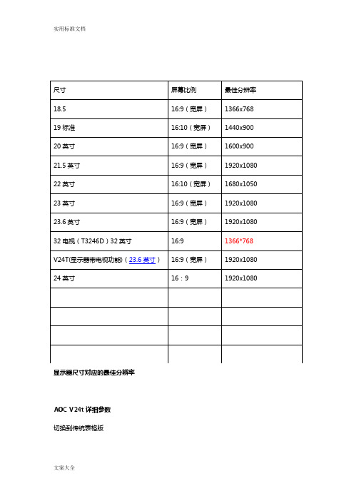
显示器尺寸对应的最佳分辨率AOC V24t详细参数切换到传统表格版基本参数显示参数面板控制接口外观设计其它显示器附件保修信息基本参数•产品定位:娱乐影音•屏幕尺寸:23.6英寸•屏幕比例:16:9(宽屏)•最大分辨率:1920x1080 •最佳分辨率:1920x1080•高清标准:1080p(全高清)•面板类型:TN•背光类型:CCFL背光•动态对比度:60000:1•黑白响应时间:5ms显示参数•点距:0.2715mm•亮度:300cd/㎡•可视面积:521.28×293.22mm •可视角度:170/160°•显示颜色:16.7M•扫描频率:水平:30-80KHz垂直:55-75Hz•带宽:148.5MHz 面板控制•控制方式:按键•语言菜单:英文,德语,法语,意大利语,西班牙语,俄语,葡萄牙语,土耳其语,简体中文接口•视频接口:D-Sub(VGA),HDMI,色差,S端子,复合信号CVBS •其它接口:TV,音频输出外观设计•机身颜色:黑色烤漆,银色底座•外观设计:超薄设计,最薄处2.5cm•产品尺寸:595.4×483.54×220.13mm(包含底座)668×565×117mm(包装)•产品重量:5.5kg(净重)7.5kg(毛重)•底座功能:倾斜•音箱:内置音箱(2×2.5W)•壁挂:100×100mm其它•电视功能:支持电视功能•HDCP:支持HDCP•电源性能:90~240V交流, 50/60Hz External Adapter•消耗功率:最大:60W待机:1W•安规认证:CCC, CB, CE, GOST,EPA •其它性能:仰角:-3-10度•其它特点:Eco Mode 5种亮度情景模式获得EPEAT金奖•上市时间:2009年06月显示器附件•包装清单:显示器主机 x1 底座 x1电源线 x1信号线 x1保修卡 x1电子光盘说明书 x1保修信息•保修政策:全国联保,享受三包服务•质保时间:3年•质保备注:整机1月内包换,2年免费上门,3年免费全保•客服电话:400-887-8007•电话备注:8:00-22:00•详细内容:在中国大陆(不包括香港、澳门特别政区)购买并在大陆地区使用的显示器,出现保修范围内的硬件故障时,凭显示器保修证正本和购机发票到“冠捷国内维修站一览表”中的任何一个维修站均可享受1个月包换,2年在规定的城市地区免费上门维修服务,3年免费保修(包含CRT及LCD面板)的123保修服务。
Taurus SeriesMultimedia PlayersTB8Specifications Doc u ment V ersion:V1.3.2Doc u ment Number:NS120100363Copyright © 2018 Xi’an NovaStar Tech Co., Ltd. All Rights Reserved.No part of this document may be copied, reproduced, extracted or transmitted in any form or by any means without the prior written consent of Xi’an NovaStar Tech Co., Ltd.Trademarkis a trademark of Xi’an NovaStar Tech Co., Ltd.Statementi TB8 SpecificationsTable of ContentsTable of ContentsYou are welcome to use the product of Xi’an NovaStar Tech Co., Ltd. (hereinafter referred to asNovaStar). This document is intended to help you understand and use the product. For accuracy and reliability, NovaStar may make improvements and/or changes to this document at any time and without notice. If you experience any problems in use or have any suggestions, please contact us via contact info given in document. We will do our best to solve any issues, as well as evaluate and implement any suggestions.Table of Contents (ii)1 Overview (1)1.1 Introduction ..................................................................................................................................................11.2 Application (1)2 Features (3)2.1 Synchronization mechanism for multi-screen playing (3)2.2 Powerful Processing Capability (3)2.3 Omnidirectional Control Plan (3)2.4 Synchronous and Asynchronous Dual-Mode (4)2.5 Dual-Wi-Fi Mode ..........................................................................................................................................42.5.1 Wi-Fi AP Mode (5)2.5.2 Wi-Fi Sta Mode (5)2.5.3 Wi-Fi AP+Sta Mode (5)3 Hardware Structure (7)3.1 Appearance (7)3.1.1 Front Panel (7)3.1.2 Rear Panel ................................................................................................................................................83.2 Dimensions (9)4 Software Structure (10)4.1 System Software (10)4.2 Related Configuration Software (10)5 Product Specifications ................................................................................................................ 116 Audio and Video Decoder Specifications (13)6.1 Image (13)6.1.1 Decoder (13)6.1.2 Encoder (13)6.2 Audio (14)6.2.1 Decoder (14)6.2.2 Encoder (14)6.3 Video (15)ii Table of Contents6.3.1 Decoder (15)6.3.2 Encoder ..................................................................................................................................................16iiiTB8 Specifications 1 Overview1 Overview 1.1 IntroductionTaurus series products are NovaStar's second generation of multimedia playersdedicated to small and medium-sized full-color LED displays.TB8 of the Taurus series products (hereinafter referred to as “TB8”) feature followingadvantages, better satisfying users’ requirements:●Loading capacity up to 2,300,000 pixels●Synchronization mechanism for multi-screen playing●Powerful processing capability●Omnidirectional control plan●Synchronous and asynchronous dual-mode●Dual-Wi-Fi mode Note:If the user has a high demand on synchronization, the time synchronization module isrecommended. For details, please consult our technical staff.In addition to solution publishing and screen control via PC, mobile phones and LAN,the omnidirectional control plan also supports remote centralized publishing andmonitoring.1.2 ApplicationTaurus series products can be widely used in LED commercial display field, such asbar screen, chain store screen, advertising machine, mirror screen, retail storescreen, door head screen, on board screen and the screen requiring no PC.Classification of Taurus’ application cases is shown in Table 1-1. Table1 Overviewaurus Series Multimedia PlayersTB8 Specifications2 Features 2.1 Synchronization mechanism for multi-screen playingThe TB8 support switching on/off function of synchronous display.When synchronous display is enabled, the same content can be played on differentdisplays synchronously if the time of different TB8 units are synchronous with oneanother and the same solution is being played.2.2 Powerful Processing CapabilityThe TB8 features powerful hardware processing capability:● 1.5 GHz eight-core processor●Support for H.265 4K high-definition video hardware decoding playback●Support for 1080P video hardware decoding● 2 GB operating memory●8 GB on-board internal storage space with 4 GB available for users2.3 Omnidirectional Control PlanControl Plan Connecting Mode User Terminal Related SoftwareSolution publishing and screen control through mobile phone Wi-Fi Mobile phone andPadViPlex HandyCluster remote solution publishing and screen control Wi-Fi AP+StaWiredMobile phone, Padand PCVNNOXViPlex HandyViPlex ExpressCluster remote monitoring Wi-Fi AP+StaWiredMobile phone, Padand PCNovaiCareViPlex HandyViPlex ExpressCluster control plan is a new internet control plan featuring following advantages:●More efficient: Use the cloud service mode to process services through a uniformplatform. For example, VNNOX is used to edit and publish solutions, andNovaiCare is used to centrally monitor display status.●More reliable: Ensure the reliability based on active and standby disasterrecovery mechanism and data backup mechanism of the server.●More safe: Ensure the system safety through channel encryption, data fingerprintand permission management.●Easier to use: VNNOX and NovaiCare can be accessed through Web. As long asthere is internet, operation can be performed anytime and anywhere.●More effective: This mode is more suitable for the commercial mode ofadvertising industry and digital signage industry, and makes informationspreading more effective.2.4 Synchronous and Asynchronous Dual-ModeThe TB8 supports synchronous and asynchronous dual-mode, allowing moreapplication cases and being user-friendly.When internal video source is applied, the TB8 is in asynchronous mode; whenHDMI-input video source is used, the TB8 is in synchronous mode. Content can bescaled and displayed to fit the screen size automatically in synchronous mode.Users can manually and timely switch between synchronous and asynchronousmodes, as well as set HDMI priority.2.5 Dual-Wi-Fi ModeThe TB8 have permanent Wi-Fi AP and support the Wi-Fi Sta mode, carryingadvantages as shown below:●Completely cover Wi-Fi connection scene. The TB8 can be connected to throughself-carried Wi-Fi AP or the external router.●Completely cover client terminals. Mobile phone, Pad and PC can be used to login TB8 through wireless network.●Require no wiring. Display management can be managed at any time, havingimprovements in efficiency.TB8’s Wi-Fi AP signal strength is related to the transmit distance and environment.Users can change the Wi-Fi antenna as required.2.5.1 Wi-Fi AP ModeUsers connect the Wi-Fi AP of a TB8 to directly access the TB8. The SSID is “AP +the last 8 digits of the SN”, for example, “AP10000033”, and the default passwordis“12345678”.Configure an external router for a TB8 and users can access the TB8 by connectingthe external router. If an external router is configured for multiple TB8 units, a LAN canbe created. Users can access any of the TB8 via the LAN.2.5.2 Wi-Fi Sta Mode2.5.3 Wi-Fi AP+Sta ModeIn Wi-Fi AP+ Sta connection mode, users can either directly access the TB8 or accessinternet through bridging connection. Upon the cluster solution, VNNOX andNovaiCare can realize remote solution publishing and remote monitoring respectivelythrough the Internet.3Hardware Structure3.1 Appearance3.1.1 Front PanelName DescriptionPWR Power status indicatorAlways on: Power input is normal.System status indicator● Flashing once every other 2 seconds: The system is operating normally.● Flashing once every other second: The system is installing the upgrade package.● Flashing once every other 0.5 second: The system isdownloading data from the Internet or copying the upgrade package.● Always on/off: The system is operating abnormally. CLOUDInternet connection status indicator● Always on: The unit is connected to the Internet and the connection status is normal.● Flashing once every other 2 seconds: The unit is connected to VNNOX and the connection status is normal.SYSFigure 3-1 Front panel of the TB8 Note: All product pictures shown in this document are for illustration purpose only. Actual product may vary.Table 3-1 Description of TB8 front panelW i Fi-S TA COM1AUDIO OUT Audio output3.1.2 RearPanelFigure 3-2 Rear panel of the TB8Note: All product pictures shown in this document are for illustration purpose only.Actual product may vary.Table 3-2 Description of TB8 rear panelName DescriptionRESET Factory reset buttonPress and hold the button for 5 seconds to reset the unit tofactory settings.LED OUT Output Ethernet portON/OFF Power switch100-240V~,50/60Hz Power inputUnit: mmaurus Series Multimedia PlayersTB8 Specifications 4 Software Structure4 Software Structure4.1 System Software●Android operating system software●Android terminal application software●FPGA programNote: The third-party applications are not supported.4.2 Related Configuration SoftwareTable 4-1 Related configuration softwareNovaLCTaurus Series Multimedia Players TB8 Specifications5 Product Specifications5Product Specifications8 GB on-board with 4 GBavailable 0°C–50°CListDimensions for usersPacking informationmensions ( H ×W×D )5 Product SpecificationsAntennaaurus Series Multimedia Players TB8 SpecificationsAudio and Video Decoder6.1.2 EncoderType Codec Supported Image SizeMaximum Data RateRemarks JPEGJPEG Baseline96×32 pixels~8176×8176 pixels90Mpixels/Second JFIF 1.02 N/A6Type Codec Supported Image Size Container RemarksJPEGJFIF1.02JPG, JPEGNot SupportNon-interleaved Scan Software support SRGB JPEGSoftware support Adobe RGB JPEGBMP BMP No Restriction BMP N/A GIF GIF No Restriction GIF N/A PNG PNG No Restriction PNG N/A WEBPWEBPNo RestrictionWEBPN/A48 × 48 p ixels~8176 × 8176 pixel sSpecifications6.1 Image6.1.1 Decoder6.2 AudioOGG, OGA8KHZ~48AMR-NB 2HZ~ 48 1H.264.6.3.2 EncoderMOV, 3GPM bps。
VTWC20 HD 1080p WebcamSKU: 901380The VisionTek VTWC20 Full HD 1080p Webcam forWindows, Mac, Linux and Chromebook systems.Crisp. Clear. At Home Video CallsVTWC20 webcam offers Full HD video (1080p 30FPS), record and sharecolorful HD quality video. Fixed focus distance lens with auto focus and a 77degree viewing angle. Onboard digital microphone for clear crisp audio.Compatible with Windows, Mac, Linux and Chromebook systems, makingthis the ideal solution for the office or home use.VisionTek VTWC20 - USB WebcamKey Features1080p (1920x1080) High Definition cameralets you present yourself clearly andprofessionally in your home or office.Fixed FocusCompatible with most video conferencingsoftware including MS Teams, Zoom, Skype,Cisco Webex, Google Meet, FacebookMessenger and more.No Drivers Required - UVC Compliantmeans no setup time and ready to go assoon as you plug it in.Privacy cover keeps your lens protected andassures you peace of mind against spywareand other hacking tools.Dual built-in digital microphone ensurecrystal clear audio so you can speak at anormal volume and still be heard.The camera allows for a 360 degreehorizontal rotation and 30 degrees of tilt tofind the best position for your setup.The tripod mount allows for additional setupoptions to find your best angle. Technical SpecificationsPart #901380InterfaceUSB 2.0Resolution Supported1920 x 1080Frame RateUp to 30 FPSPixels2 millionViewing Angle:77ºFocusFixedMicrophoneDigitalCable Length1.7mWorking Temperature-10 to 40º CPower Consumption<1.25 WSystem RequirementsOperating SystemWindows 10Windows 8Windows 7macOS 10.9 or aboveLinuxChromeOSConnection PortUSB 2.0 PortWarrantyWarranty:1 Year Limited*You may register your product here: /support/warranty-registrationFor additional warranty information, please see our Warranty Page: /support/warranty-informationWhat's In The BoxVTWC20 WebcamQuick Start GuideSupportDriversNo drivers required UVC Plug N PlayOBS Studio Setup1) After having installed OBS Studio navigate to the lower left section to find a column titled “Sources”. Underneath the column there will be a “+” button, click on it to open another window.2) In this window you will need to select “Video Capture Device”. Once selected, a new window will appear, make sure you have “Create New” selected and then you can name it whatever you would like. For simplicity sake, we suggest naming it “VisionTek VTWC20”. Click OK once this has been completed.3) A new window will appear with a preview of the source you are adding. You will need to select the device in which you would like for the source. Please select "VisionTek VTWC20” and click “OK” to complete the source creation. The video and audio feed from the capture card should not be recognized in OBS Studio.Streamlabs OBS Setup1) After having installed Streamlabs OBS navigate to the lower middle section to find a column titled “Sources”. Near the top of the column there will be a “+” button, click on it to open another window.2) In this window you will need to select “Video Capture Device”. Once selected, click “add source” and a new window will appear, make sure you click “Add a new source instead” selected and then you can name it whatever you would like. For simplicity sake, we suggest naming it “VisionTek VTWC20”. Click “Add Source”once this has been completed.3) A new window will appear with a preview of the source you are adding. You will need to select the device in which you would like for the source. Please select “VisionTek VTWC20”. Scroll to the bottom of this window and check the box titled “Use custom audio device” (if this is not checked, there will be no video feed). Click “Done” to complete the source creation. The video and audio feed from the capture card should now be recognized in OBS Studio.Microsoft Teams Setup1) Open the Microsoft Teams App.2) Click on the user icon in the upper right corner and select settings from the menu.3) Select Devices on the left settings menu, under the camera dropdown select VisionTek VTWC20. The source should appear in the preview window.4) Click the X in the upper right corner of the Settings Window to save the settings.Zoom Setup1) Open the Zoom App and log in.2) Click the settings icon in the upper right corner to open the settings window.3) Select Video from the left side menu.4) Under the Camera drop down select VisionTek VTWC20.5) Click the X in the upper right corner of the Settings Window to save the settings.FAQHow do I test to see if my camera is functioning?Check to see if the webcam is recognized in Windows Device Manager or Mac OS System report. In Windows 7, 8.1, and 10 the camera application can be launched to not only make sure the webcam is functional but also to tune the focus of the webcam if your model is manual focus (VTWC30). The camera application can be launched by either searching for the application or launching it from the All Programs menu.Why is my camera out of focus?The VTWC40 is an auto focus camera. Move your hand in front of the camera and pull it back towards you body for the sensor to find a focal point.The VTWC30 is a manual focus camera. To adjust the focus, rotate the knob that houses the camera lens until you achieve the desired focus.The VTWC20 is a fixed focus camera and will always have a consistent focal distance which means you may need to adjust the distance between you and the webcam for best results. Be sure to open the camera application on your system to help determine when the focus is set in the proper location.Is there a way to adjust the brightness of the video when under bright lights?The webcams come standard with advanced built-in parameter adjustment chips. When the video is too bright, face the camera at the ceiling or white wall so that the camera can automatically reduce brightness. Readjust the camera back to its original position and the video will revert to normal brightness.Why am I getting horizontal lines in images?The horizontal lines are caused by light refraction. If you adjust the angle of the camera, the screen will come back to normal. Some overhead LED lighting systems may also cause the horizontal lines, there is no way to fix this besides turning off the lights.Why does the image flash when the computer is used online?When the image flashes, adjust the angle of the camera and the focus should reset.How do I improve the image quality while my system is in use?Light plays a very important role in image quality. Adjust your webcam angle to adjust lighting conditions. Natural daylight or bright white bulbs are the best options for optimal image quality.Why is the image reversed after installation? Is there a way to change it?For Windows XP SP1 or Windows XP SP2, the image is reversed if the USB port being used is USB1.1. We recommend installing the Service Pack that includes “AMCAP”. Go into Properties > Reverse and remove the checkmark.I use Windows Me, is there a driver I can download to use the webcam?Unfortunately, Windows Me and Windows 98 are not supported.Why is the image on my system not as clear as expected?Using the latest Microsoft Service Pack and the USB 2.0 or 3.0 port will improve the image quality. Most newer systems will not experience this issue.Why is my webcam acting slow or there is a delay in the image?Try restarting your computer as this may solve the issue. Ensure that the webcam is recognized properly in Windows Device Manager or MacOS System Report. If the issue happens only while using your video chat application, check your internet connection bandwidth and/or adjust the quality settings in your video chat application. Make sure that the webcam is connected directly to a High-Speed USB 2.0 or 3.0, preferably the one at the rear if you are using a desktop computer.Connect the webcam directly to the computer. Try to bypass your Dock, USB hub, USB extension cable, USB port of monitor or keyboard. If you still experience problems, try connecting the webcam to another computer.Why does the microphone produce a noise and muffled sound in Windows?To resolve this, go to the Windows sound settings and configure the bit depth and sample rate of your webcam's microphone to?2 channel, 16 bit, 44100Hz (CD Quality).How do I enable my built-in microphone?First, ensure that your device is connected to your PC or Mac. In Windows, navigate to your sound settings. Under the input selection, choose the VisionTek Webcam Microphone as the device you would like to use. To enable the webcam Microphone in video conferencing software (Microsoft Teams, Zoom, Skype, Etc.) you will need to open the video conference software and navigate to the settings section. From there, locate the audio settings and then select the Webcam Microphone as the default input device. In Mac OS, go into utilities and find Audio MIDI Setup. From there choose the Webcam Device and select use this device for sound input. Why does the webcam not work when used online?If the webcam stops functioning correctly when going online, a simple system restart should resolve the issue. If you are still experiencing issues, please contact our support department for assistance.What do I do if there is no image being displayed when the camera is connected properly?In the event you are connecting to a system that already has another webcam or media capture device connected, you will need to select the VisionTek Webcam as the source instead of a different option. This selection can be made in most video conference services. In some cases, Windows will have a “camera switch” icon that can be pressed which will change video capture sources.How do I know if my webcam is being detected in macOS?Click the Apple logo in the upper left corner and select “About This Mac”. When the window appears, click on “System Report”. Select “Audio” on the left and the VisionTek Webcam will appear in the list of devices. Next, click on “Camera” and the VisionTek webcam will appear as a camera device.How do I test the webcam's microphone input on macOS?Go to System Preferences, and then Sound. Under the input tab be sure that you have the VisionTek Webcam selected. Try speaking into the microphone and observe the input volume bar indicate that audio is being detected. Please be sure that the mute box is unchecked.How do I test the webcam's video functionality in macOS?Launch Facetime and select the video menu from the top. From there, please select the VisionTek Webcam under the camera devices.How do I test the webcam microphone in Windows OS?Open sound settings and make sure the input device is set to the VisionTek Webcam Microphone. From there, speak into the webcam microphone and watch for the volume bar to move indicating that audio is being detected.How do I test the webcam video functionality in Windows OS?In Windows the Camera Application can be launched to not only make sure the webcam is functional but also to tune the focus of the webcam if your model is manual focus (VTWC30). The camera application can be launched by either searching for the application or launching it from the All Programs menu.For California Residents Only:WARNING: Cancer and Reproductive harm. For more information, go to * Please, Note that Proposition 65 may be best defined as a “Right To Know” law in California and Prop 65 warning labels are not an indication that a product is violating safety standards or regulations. The Prop 65 warning label does not mean our products inevitably cause cancer or reproductive harm. We do not consider our products harmful when used as intended. However, it is a necessary precaution to provide the warning because of this California law.。
Model Name: T420HW07 V0Issue Date : 2009/10/07(*)Preliminary Specifications( )Final SpecificationsCustomer Signature Date AUO DateApproved By_________________________________ Approval By PM DirectorFrank Hsu____________________________________Reviewed By RD DirectorEugene CC Chen____________________________________ Reviewed By Project LeaderWayne. NC. Lee____________________________________NotePrepared By PMAlex CC Wang____________________________________ContentsNoCONTENTSRECORD OF REVISIONS1 GENERAL DESCRIPTION2 ABSOLUTE MAXIMUM RATINGS3 ELECTRICAL SPECIFICATION3-1 ELECTRIACL CHARACTERISTICS3-2 INTERFACE CONNECTIONS3-3 SIGNAL TIMING SPECIFICATION3-4 SIGNAL TIMING WAVEFORM3-5 COLOR INPUT DATA REFERENCE3-6 POWER SEQUENCE3-7 BACKLIGHT SPECIFICATION4 OPTICAL SPECIFICATION5 MECHANICAL CHARACTERISTICS6 RELIABILITY TEST ITEMS7 INTERNATIONAL STANDARD7-1 SAFETY7-2 EMC8 PACKING8-1 DEFINITION OF LABEL8-2 PACKING METHODS8-3 PALLET AND SHIPMENT INFORMATION9 PRECAUTION9-1 MOUNTING PRECAUTIONS9-2 OPERATING PRECAUTIONS9-3 ELECTROSTATIC DISCHARGE CONTROL9-4 PRECAUTIONS FOR STRONG LIGHT EXPOSURE9-5 STORAGE9-6 HANDLING PRECAUTIONS FOR PROTECT FILMRecord of RevisionVersion Date Page Description0.0 2009/10/07 First release1. General DescriptionThis specification applies to the 42.0 inch Color TFT-LCD Module T420HW07 V0. This LCD module has a TFT active matrix type liquid crystal panel 1,920x1,080 pixels, and diagonal size of 42.0 inch. This module supports 1,920x1080 mode. Each pixel is divided into Red, Green and Blue sub-pixels or dots which are arranged in vertical stripes. Gray scale or the brightness of the sub-pixel color is determined with a 10-bit gray scale signal for each dot.The T420HW07 V0 has been designed to apply the 10-bit 4 channel LVDS interface method. It is intended to support displays where high brightness, wide viewing angle, high color saturation, and high color depth are very important.* General InformationItems Specification Unit NoteActive Screen Size 42.00 inchDisplay Area 581.8.6(H) x 328.8(V) mmOutline Dimension 973.2(H) x 566.2 (V) x 22.4(D) mm D : Front bezel to T-CON cover Driver Element a-Si TFT active matrixDisplay Colors 10 bit(8+FRC), 1073.7M ColorsNumber of Pixels 1,920x1080 PixelPixel Pitch 0.21 (H) x 0.63(W) mmPixel Arrangement RGB vertical stripeDisplay Operation Mode Normally BlackSurface Treatment Anti-Glare, 3H Haze=13%2. Absolute Maximum RatingsThe followings are maximum values which, if exceeded, may cause faulty operation or damage to the unitItem Symbol Min Max Unit Conditions Logic/LCD Drive Voltage Vcc -0.3 14 [Volt] Note 1Input Voltage of Signal Vin -0.3 4 [Volt] Note 1Operating Temperature TOP 0 +50 [o C] Note 2Operating Humidity HOP 10 90 [%RH] Note 2Storage Temperature TST -20 +60 [o C] Note 2Storage Humidity HST 10 90 [%RH] Note 2Panel Surface Temperature PST 65 [o C] Note 3Note 1: Duration:50 msec.℃Note 2 : Maximum Wet-Bulb should be 39 and No condensation.℃The relative humidity must not exceed 90% non-condensing at temperatures of 40or less. At temperatures greater than 40, the wet bulb temperature must not exceed 39.℃℃Note 3: Surface temperature is measured at 50℃ Dry condition3. Electrical SpecificationThe T420HW07 V0 requires two power inputs. One is employed to power the LCD electronics and to drive the TFT array and liquid crystal. The second is employed for LED driver.3.1 Electrical CharacteristicsValueParameter SymbolMin. Typ. MaxUnit Note LCDPower Supply Input Voltage V DD10.8 12 13.2 V DC 1 Power Supply Input Current I DD- 0.9 1.2 A 2 Power Consumption P C TBD 10.8 TBD Watt 2 Inrush Current I RUSH- - 4 A 3 Differential Input High ThresholdVoltageV TH-- -- +100 mV DC 4Differential Input Low Threshold Voltage V TL-100 -- -- mV DC 4LVDSInterfaceInput Common Mode Voltage V ICM 1.1 1.25 1.4 V DC 4 LVDSInterfaceInput Channel Pair Skew Margin t SKEW (CP)-500 -- +500 ps 5Input High Threshold VoltageV IH(High)2.7 --3.3 V DCCMOSInterfaceInput Low Threshold VoltageV IL(Low)0 -- 0.6 V DCBacklight Power Consumption P BL TBD 105 115 WattLife Time (MTTF) 30000 -- Hours 8Note :1. The ripple voltage should be controlled under 10% of V CC2. Test Condition:(1) V DD = 12.0V(2) Fv = Type Timing, 60Hz, 120Hz or Other(3) F CLK = Max freq.(4) Temperature = 25 ℃(5) Test Pattern : White Pattern3.Measurement condition : Rising time = 400usG D D4. V ICM = 1.25VV0V5.Input Channel Pair Skew Margin3.2 Interface ConnectionsLCD connector : P-TWO 187059-5122Mating connector :PIN Symbol Description PIN Symbol Description1 Reserved AUO Internal Use Only 26 GND Ground2 Reserved AUO Internal Use Only 27 GND Ground3 NC No connection 28 CH2_0- LVDS Channel 2, Signal 0-4 Reserved AUO Internal Use Only 29 CH2_0+ LVDS Channel 2, Signal 0+5 NC No connection 30 CH2_1- LVDS Channel 2, Signal 1-6 NC No connection 31 CH2_1+ LVDS Channel 2, Signal 1+7 LVDS_SEL Open/High(3.3V) for NS,Low(GND) for JEIDA32 CH2_2- LVDS Channel 2, Signal 2-8 Reserved AUO Internal Use Only 33 CH2_2+ LVDS Channel 2, Signal 2+9 Reserved AUO Internal Use Only 34 GND Ground10 Reserved AUO Internal Use Only 35 CH2_CLK- LVDS Channel 2, Clock -11 GND Ground 36 CH2_CLK+ LVDS Channel 2, Clock +12 CH1_0- LVDS Channel 1, Signal 0- 37 GND Ground13 CH1_0+ LVDS Channel 1, Signal 0+ 38 CH2_3- LVDS Channel 2, Signal 3-14 CH1_1- LVDS Channel 1, Signal 1- 39 CH2_3+ LVDS Channel 2, Signal 3+15 CH1_1+ LVDS Channel 1, Signal 1+ 40 CH2_4- LVDS Channel 2, Signal 4-16 CH1_2- LVDS Channel 1, Signal 2- 41 CH2_4+ LVDS Channel 2, Signal 4+17 CH1_2+ LVDS Channel 1, Signal 2+ 42 GND Ground18 GND Ground 43 GND Ground19 CH1_CLK- LVDS Channel 1, Clock - 44 GND Ground20 CH1_CLK+ LVDS Channel 1, Clock + 45 GND Ground21 GND Ground 46 GND Ground22 CH1_3- LVDS Channel 1, Signal 3- 47 NC No connection23 CH1_3+ LVDS Channel 1, Signal 3+ 48 V DD Power Supply, +12V DC Regulated24 CH1_4- LVDS Channel 1, Signal 4- 49 V DD Power Supply, +12V DC Regulated25 CH1_4+ LVDS Channel 1, Signal 4+ 50 V DD Power Supply, +12V DC Regulated51 V DD Power Supply, +12V DC RegulatedT420HW07 V0 Product SpecificationRev. 00 LCD connector: P-TWO 187060-4122Mating connector:PIN Symbol Description PIN Symbol Description1 NC No connection 21 CH3_3+ LVDS Channel 3, Signal 3+2 Reserved AUO Internal Use Only 22 CH3_4- LVDS Channel 3, Signal 4-3 Reserved AUO Internal Use Only 23 CH3_4+ LVDS Channel 3, Signal 4+4 NC No connection 24 GND Ground5 Reserved AUO Internal Use Only 25 GND Ground6 Reserved AUO Internal Use Only 26 CH4_0- LVDS Channel 4, Signal 0-7 NC No connection 27 CH4_0+ LVDS Channel 4, Signal 0+8 NC No connection 28 CH4_1- LVDS Channel 4, Signal 1-9 GND Ground 29 CH4_1+ LVDS Channel 4, Signal 1+10 CH3_0- LVDS Channel 3, Signal 0- 30 CH4_2- LVDS Channel 4, Signal 2-11 CH3_0+ LVDS Channel 3, Signal 0+ 31 CH4_2+ LVDS Channel 4, Signal 2+12 CH3_1- LVDS Channel 3, Signal 1- 32 GND Ground13 CH3_1+ LVDS Channel 3, Signal 1+ 33 CH4_CLK- LVDS Channel 4, Clock -14 CH3_2- LVDS Channel 3, Signal 2- 34 CH4_CLK+ LVDS Channel 4, Clock +15 CH3_2+ LVDS Channel 3, Signal 2+ 35 GND Ground16 GND Ground 36 CH4_3- LVDS Channel 4, Signal 3-17 CH3_CLK- LVDS Channel 3, Clock - 37 CH4_3+ LVDS Channel 4, Signal 3+18 CH3_CLK+ LVDS Channel 3, Clock + 38 CH4_4- LVDS Channel 4, Signal 4-19 GND Ground 39 CH4_4+ LVDS Channel 4, Signal 4+20 CH3_3- LVDS Channel 3, Signal 3- 40 GND Ground41 GND GroundT420HW07 V0 Product SpecificationRev. 00 LVDS Option = High/Open NSC loC HC HC HC HC HC HC HC HC HC HNote: x = 1, 2, 3, 4…C loC HC HC HC HC HC HC HC HC HC HNote: x = 1, 2, 3, 4…T420HW07 V0 Product Specification Rev. 003.3 Signal Timing SpecificationThis is the signal timing required at the input of the user connector. All of the interface signal timing should be satisfied with the following specifications for its proper operation.Timing TableSignal Vertical SectionItem Period Active Blanking PeriodSymbol Tv Tdisp (v) Tblk (v) Th Tdisp (h) Tblk (h) Fclk=1/Tclk Fv FhMin. 1090 10 540 60 64.8 94 120Typ. 1130 1080 50 570 480 90 77.29 120 135.6Max 1392 312 580 100 80.74 122 139.2Unit Th Th Th Tclk Tclk Tclk MHz Hz KHzHorizontal Section Clock Vertical Frequency Horizontal FrequencyNotes:Active Blanking Frequency Frequency Frequency(1) Display position is specific by the rise of DE signal only. Horizontal display position is specified by the rising edge of 1st DCLK after the rise of 1st DE, is displayed on the left edge of the screen. (2)Vertical display position is specified by the rise of DE after a “Low” level period equivalent to eight times of horizontal period. The 1st data corresponding to one horizontal line after the rise of 1st DE is displayed at the top line of screen. (3)If a period of DE “High” is less than 1920 DCLK or less than 1080 lines, the rest of the screen displays black. (4)The display position does not fit to the screen if a period of DE “High” and the effective data period do not synchronize with each other.© Copyright AUO Optronics Corp. 2009 All Rights Reserved.Page 11 / 29T420HW07 V0 Product Specification Rev. 00Tv N Line Tblk(v) Th DE RGB Data CLK Tclk Th Tdisp(h) Tblk(h)Line N Invalid Data Line 1 Line 2 Line 3 Line 4 Line NM pixel Tdisp(v)Invalid DataDECH1Pixel M-15Pixel M-11Pixel M-7Pixel M-3Invalid DataPixel 1Pixel 5Pixel 9Pixel 13Pixel 17Pixel 21Pixel M-11Pixel M-7Pixel M-3Invalid DataPixel 1Pixel 5CH2 CH3Pixel M-14Pixel M-10Pixel M-6Pixel M-2Invalid DataPixel 2Pixel 6Pixel 10Pixel 14Pixel 18Pixel 22Pixel M-10Pixel M-6Pixel M-2Invalid DataPixel 2Pixel 6Pixel M-13Pixel M-9Pixel M-5Pixel M-1Invalid DataPixel 3Pixel 7Pixel 11Pixel 15Pixel 19Pixel 23Pixel M-9Pixel M-5Pixel M-1Invalid DataPixel 3Pixel 7CH4Pixel M-12Pixel M-8Pixel M-4Pixel MInvalid DataPixel 4Pixel 8Pixel 12Pixel 16Pixel 20Pixel 24Pixel M-8Pixel M-4Pixel MInvalid DataPixel 4Pixel 8© Copyright AUO Optronics Corp. 2009 All Rights Reserved.3.4 Signal Timing WaveformsPage 12 / 29T420HW07 V0 Product Specification Rev. 003.5 Color Input Data ReferenceThe brightness of each primary color (red, green and blue) is based on the 10 bit gray scale data input for the color; the higher the binary input, the brighter the color. The table below provides a reference for color versus data input.COLOR DATA REFERENCEInput Color Data Color MSB RED LSB MSB GREEN LSB MSB BLUE LSBR9 R8 R7 R6 R5 R4 R3 R2 R1 R0 G9 G8 G7 G6 G5 G4 G3 G2 G1 G0 B9 B8 B7 B6 B5 B4 B3 B2 B1 B0 Black Red(1023) Green(1023) Basic Blue(1023) Color Cyan Magenta Yellow White RED(000) RED(001) R ---RED(1022) RED(1023) GREEN(000) GREEN(001) G ---GREEN(1022) 0 GREEN(1023) 0 BLUE(000) BLUE(001) B ---BLUE(1022) BLUE(1023) 0 0 0 0 0 0 0 0 0 0 0 0 0 0 0 0 0 0 0 0 0 0 0 0 0 0 0 0 0 0 0 0 0 0 0 0 0 0 0 1 1 1 1 1 1 1 1 1 0 0 1 1 1 1 1 1 1 1 1 1 0 0 0 0 0 0 0 0 0 0 0 0 0 0 0 0 0 0 0 0 0 0 0 0 0 0 0 0 0 0 0 0 0 0 0 0 0 0 1 1 0 0 1 1 0 0 1 1 0 0 1 1 0 0 1 1 0 0 1 1 0 0 1 1 0 0 1 1 0 0 1 1 0 0 0 0 0 0 0 0 0 0 0 0 0 1 0 0 0 0 0 0 0 0 0 0 0 0 0 0 0 0 0 0 0 0 0 0 0 0 0 0 0 0 0 0 0 1 1 1 0 0 1 1 1 1 1 1 1 1 0 1 1 1 1 1 1 1 1 1 0 0 0 0 0 0 0 0 0 0 0 0 0 0 0 0 0 0 0 0 0 0 0 0 0 0 0 0 0 0 0 0 0 0 0 0 0 0 0 0 0 0 0 0 0 0 0 0 0 0 0 0 0 0 0 0 0 0 0 0 0 0 0 0 0 0 0 0 0 0 0 0 0 0 0 0 0 0 0 0 0 0 0 0 0 0 0 1 0 0 0 0 0 0 0 0 0 0 0 1 0 0 0 1 1 1 0 0 0 0 0 0 0 0 0 0 0 1 1 1 1 1 1 1 1 1 0 0 0 0 0 0 0 0 0 0 0 0 0 0 0 0 0 0 0 0 0 0 0 0 0 0 0 1 1 1 1 1 1 1 1 1 1 1 1 1 1 1 1 1 1 1 1 1 1 1 1 1 1 1 0 0 0 0 0 0 0 0 0 0 0 0 0 0 0 0 0 1 0 0 1 0 1 0 1 1 0 0 0 0 1 0 1 0 1 1 0 0 0 0 1 0 1 0 1 1 0 0 0 0 1 0 1 0 1 1 0 0 0 0 1 0 1 0 1 1 0 0 0 0 1 0 1 0 1 1 0 0 0 0 1 0 1 0 1 1 0 0 0 0 1 0 1 0 1 1 0 0 0 0 1 0 1 0 1 1 0 0 0 0 0 0 0 0 0 0 0 0 0 0 0 0 0 0 0 0 0 0 0 0 1 0 0 0 0 0 0 0 0 0 0 0 1 1 1 1 1 1 1 1 1 1 1 1 1 1 1 1 1 1 1 1 1 0 1 1 1 1 1 1 1 1 1 1 1 0 0 0 0 0 0 0 0 0 0 1 1 1 1 1 1 1 1 1 1 1 0 0 0 0 0 0 0 0 0 0 0 0 0 0 0 0 0 0 0 0 0 0© Copyright AUO Optronics Corp. 2009 All Rights Reserved.Page 13 / 29T420HW07 V0 Product Specification Rev. 003.6 Power Sequence for LCDParameter t1 t2 t3 t4 t5 t6 t7Note:Values Min. 0.4 0.1 300 0*1Type. ---------------Max. 30 ----------*2Unit ms ms ms ms ms ms ms0 --500---(1) T4=0 : concern for residual pattern before BLU turn off. (2) T6 : voltage of VDD must decay smoothly after power-off. (customer system decide this value)© Copyright AUO Optronics Corp. 2009 All Rights Reserved.Page 14 / 29T420HW07 V0 Product Specification Rev. 003.7 Backlight SpecificationThe backlight unit contains 4pcs LED lightbar3.7.1 Electrical specificationSpec Item 1 2 3 4 Input Voltage Input Current Input Power Inrush Current Symbol VDDB IDDB PDDB IRUSH ON 5 On/Off control voltage VBLON OFF IBLON MAX 7 Dimming Control Voltage V_DIM MIN 8 Dimming Control Current 9 Internal Dimming Ratio External PWM Control Voltage External PWM Control Current I_DIM DIM_R MAX V_EPWM MIN I_EPWM D_EPWM F_EPWM VDDB=24V VDDB=24V VDDB=24V VDDB=24V 0 10 140 180 0.8 2 100 240 mADC % Hz VDDB=24V VDDB=24V VDDB=24V VDDB=24V 20 2 0 2 100 3.3 VDC 3 VDC mADC % 3 VDDB=24V 0 VDDB=24V 3.0 0.8 1.5 3.3 mA VDC Condition Min VDDB=24V VDDB=24V VDDB=24V 21.6 4.04 97 2 Typ 24 4.4 105 Max 26.4 4.89 117 6 5.5 VDC VDC ADC W ADC 1 1 2 Unit Note6On/Off control current101112 External PWM Duty ratio 13 External PWM FrequencyNote 1 : Dimming ratio= 100% (MAX)( Ta=25±5℃, Turn on for 45minutes) Note 2: Measurement condition Rising time = 20ms (VDDB : 10%~90%); Note 3: Less than10% dimming control is functional well and no backlight shutdown happened© Copyright AUO Optronics Corp. 2009 All Rights Reserved.Page 15 / 29T420HW07 V0 Product Specification Rev. 003.7.2 Input Pin AssignmentLED driver board connector : Cvilux CI0114M1HR0-NHPin 1 2 3 4 5 6 7 8 9 10 11Symbol VDDB VDDB VDDB VDDB VDDB BLGND BLGND BLGND BLGND BLGND DETDescription Operating Voltage Supply, +24V DC regulated Operating Voltage Supply, +24V DC regulated Operating Voltage Supply, +24V DC regulated Operating Voltage Supply, +24V DC regulated Operating Voltage Supply, +24V DC regulated Ground and Current Return Ground and Current Return Ground and Current Return Ground and Current Return Ground and Current Return BLU status detection: Normal : 0~0.8V ; Abnormal : Open collector BLU On-Off control:12VBLONHigh/Open (3.3V) : BL On ; Low (-0.3~0.8V/GND) : BL Off Internal PWM (0~3.3V for 20~100% Duty, open for 100%)13VDIM(**) < NC ; at External PWM mode> External PWM (10%~100% Duty, open for 100%)14PDIM(*) < NC ; at Internal PWM mode>(Note*) IF External PWM function includes 10% dimming ratio. Judge condition as below: (1) Backlight module must be lighted ON normally. (2) All protection function must work normally. (3) Uniformity and flicker could NOT be guaranteed© Copyright AUO Optronics Corp. 2009 All Rights Reserved.Page 16 / 29T420HW07 V0 Product Specification Rev. 004. Optical SpecificationOptical characteristics are determined after the unit has been ‘ON’ and stable for approximately 45 minutes in a dark environment at 25° C. The values specified are at an approximate distance 50cm from the LCD surface at a viewing angle of φ and θ equal to 0° . Fig.1 presents additional information concerning the measurement equipment and method.SR3 or equivalentValues Parameter Contrast Ratio Surface Luminance (White) Luminance Variation Response Time (G to G) Color Gamut Color Coordinates Red RX RY Green GX GY Blue BX BY White WX WY Viewing Angle x axis, right(φ=0° ) y axis, up(φ=90° ) x axis, left(φ=180° ) y axis, down (φ=270° ) θr θu θl ----89 89 89 89 ----degree degree degree degree Typ.-0.03 0.640 0.330 0.281 0.590 0.144 0.060 0.280 0.290 5 Typ.+0.03 Symbol Min. CR LWH δWHITE(9P) Tγ 3200 360 --Typ. 4000 450 -6.5 72 Max --1.3 -Ms % cd/m2 1 2 3 4 Unit NotesNTSCθd© Copyright AUO Optronics Corp. 2009 All Rights Reserved.Page 17 / 29T420HW07 V0 Product Specification Rev. 00Note: 1. Contrast Ratio (CR) is defined mathematically as: Surface Luminance of Lon5 Contrast Ratio= Surface Luminance of Loff52. Surface luminance is luminance value at point 5 across the LCD surface 50cm from the surface with all pixels displaying white. From more information see FIG 2. When lamp current IH = 11mA. the luminance with all pixels displaying white at center 5 location. 3. The variation in surface luminance, δWHITE is defined (center of Screen) as: 4. Response time Tγ is the average time required for display transition by switching the input signal for five luminance ratio (0%,25%,50%,75%,100% brightness matrix) and is based on Fv=60Hz to optimize. δWHITE(9P)= Maximum(Lon1, Lon2,…,Lon9)/ Minimum(Lon1, Lon2,…Lon9) LWH=Lon5 where Lon5 isMeasured Response Time 0% 25% Start 50% 75% 100%25% to 0% 50% to 0% 75% to 0% 100% to 0% 50% to 25% 75% to 25% 100% to 25%Target 0% 25%0% to 25%50%0% to 50% 25% to 50%75%0% to 75% 25% to 75% 50% to 75%100%0% to 100% 25% to 100% 50% to 100% 75% to 100%75% to 50% 100% to 50% 100% to 75%4. Viewing angle is the angle at which the contrast ratio is greater than 10. The angles are determined for the horizontal or x axis and the vertical or y axis with respect to the z axis which is normal to the LCD surface. For more information see FIG4.FIG. 2 LuminanceVH/2123456H78H/6 V/6 V/2© Copyright AUO Optronics Corp. 2009 All Rights Reserved.Page 18 / 29T420HW07 V0 Product Specification Rev. 00FIG.3 Response Time The response time is defined as the following figure and shall be measured by switching the input signal for “any level of grey(bright) “ and “any level of gray(dark)”. Any level of gray (Bright) Any level of gray (Dark) Any level of gray (Bright)0%, 25%, 50%, 75%, 100%0%, 25%, 50%, 75%, 100%FIG.4 Viewing Angle© Copyright AUO Optronics Corp. 2009 All Rights Reserved.Photodetector Output0% , 25% , 50% , 75% , 100%TimeT γ (F)T γ (R)Page 19 / 29T420HW07 V0 Product Specification Rev. 005. Mechanical CharacteristicsThe contents provide general mechanical characteristics for the model T420HW07 V0. In addition the figures in the next page are detailed mechanical drawing of the LCD.Horizontal Vertical Depth Horizontal Bezel Opening Vertical Horizontal Active Display Area Vertical Weight Surface Treatment 8700 g (Typ.) Anti-Glare, 3H973.2 mm 566.2 mm 22.4 mm (Front bezel to T-CON cover) 937.2 mm 530.2 mm 930.24 mm 523.26 mmOutline Dimension© Copyright AUO Optronics Corp. 2009 All Rights Reserved.Page 20 / 29Front ViewBack View6. Reliability Test ItemsTest Item Q’ty Condition1 High temperature storage test 3 60℃, 300hrs2 Low temperature storage test3 -20℃, 300hrs3 High temperature operation test 3 50℃, 300hrs4 Low temperature operation test 3 -5℃, 300hrs5 Vibration test (non-operation) 3 Wave form: random Vibration level: 1.5G RMS Bandwidth: 10-300Hz, Duration: X, Y, Z 30min One time each direction6 Shock test (non-operation) 3 Shock level: 50GWaveform: half since wave, 11ms Direction: ±X, ±Y, ±Z, One time each direction7 Vibration test (With carton) 3 Random wave (1.5G RMS, 10-200Hz) 30mins/ Per each X,Y,Z axes8 Drop test (With carton) 1 (PKG) Height: 25.4 cm 6 surfaces (ASTMD4169-I)7. International Standard7.1 Safety(1) UL 60950-1, UL 60065; Standard for Safety of Information Technology Equipment Includingelectrical Business Equipment.(2) IEC 60950-1 : 2001, IEC 60065:2001 ; Standard for Safety of International ElectrotechnicalCommission(3) EN 60950 : 2001+A11, EN 60065:2002+A1:2006; European Committee for ElectrotechnicalStandardization (CENELEC), EUROPEAN STANDARD for Safety of Information TechnologyEquipment Including Electrical Business Equipment.7.2 EMC(1) ANSI C63.4 “Methods of Measurement of Radio-Noise Emissions from Low-Voltage Electrical andElectrical Equipment in the Range of 9kHz to 40GHz. “American National standards Institute(ANSI),1992(2) C.I.S.P.R “Limits and Methods of Measurement of Radio Interface Characteristics of InformationTechnology Equipment.” International Special committee on Radio Interference.(3) EN 55022 “Limits and Methods of Measurement of Radio Interface Characteristics of InformationTechnology Equipment.” European Committee for Electrotechnical Standardization. (CENELEC),19988. Packing8-1 DEFINITION OF LABEL: A. Panel Label:*xxxxxxxxxxxx-xxxx*Green mark description(1) For Pb Free Product, AUO will addfor identification.(2) For RoHs compatible products, AUO will add RoHS for identification.Note: The green Mark will be present only when the green documents have been ready by AUO internal green team. (definition of green design follows the AUO green design checklist.)B. Carton Label:Panel Unique ID AUO Internal Use8-2 PACKING METHODS:8-3 Pallet and Shipment InformationSpecificationItemQty. DimensionWeight (kg)Packing Remark 1 Packing BOX 12pcs/box 1060(L)*560(W)*660(H) 100 2 Pallet11150(L)*1070(W)*138(H)163 Boxes per Pallet 2 boxes/pallet4 Panels per Pallet24pcs/palletPallet after packing 241150(L)*1070(W)*798(H)1169. PRECAUTIONSPlease pay attention to the followings when you use this TFT LCD module.9-1 MOUNTING PRECAUTIONS(1) You must mount a module using holes arranged in four corners or four sides.(2) You should consider the mounting structure so that uneven force (ex. twisted stress) is not appliedto module. And the case on which a module is mounted should have sufficient strength so thatexternal force is not transmitted directly to the module.(3) Please attach the surface transparent protective plate to the surface in order to protect the polarizer.Transparent protective plate should have sufficient strength in order to the resist external force.(4) You should adopt radiation structure to satisfy the temperature specification.(5) Acetic acid type and chlorine type materials for the cover case are not desirable because the formergenerates corrosive gas of attacking the polarizer at high temperature and the latter cause circuitbroken by electro-chemical reaction.(6) Do not touch, push or rub the exposed polarizer with glass, tweezers or anything harder than HBpencil lead. And please do not rub with dust clothes with chemical treatment. Do not touch thesurface of polarizer for bare hand or greasy cloth. (Some cosmetics are detrimental to the polarizer.)(7) When the surface becomes dusty, please wipe gently with absorbent cotton or other soft materialslike chamois soaks with petroleum benzene. Normal-hexane is recommended for cleaning theadhesives used to attach front/ rear polarizer. Do not use acetone, toluene and alcohol becausethey cause chemical damage to the polarizer.(8) Wipe off saliva or water drops as soon as possible. Their long time contact with polarizer causesdeformations and color fading.(9) Do not open the case because inside circuits do not have sufficient strength.9-2 OPERATING PRECAUTIONS(1) The device listed in the product specification sheets was designed and manufactured for TVapplication(2) The spike noise causes the mis-operation of circuits. It should be lower than following voltage:V=±200mV(Over and under shoot voltage)(3) Response time depends on the temperature. (In lower temperature, it becomes longer..)(4) Brightness of CCFL depends on the temperature. (In lower temperature, it becomes lower.) And inlower temperature, response time (required time that brightness is stable after turned on) becomeslonger.(5) Be careful for condensation at sudden temperature change. Condensation makes damage topolarizer or electrical contacted parts. And after fading condensation, smear or spot will occur.(6) When fixed patterns are displayed for a long time, remnant image is likely to occur.(7) Module has high frequency circuits. Sufficient suppression to the electromagnetic interference shallbe done by system manufacturers. Grounding and shielding methods may be important to minimize the interface.9-3 ELECTROSTATIC DISCHARGE CONTROLSince a module is composed of electronic circuits, it is not strong to electrostatic discharge. Make certain that treatment persons are connected to ground through wristband etc. And don’t touch interface pin directly.9-4 PRECAUTIONS FOR STRONG LIGHT EXPOSUREStrong light exposure causes degradation of polarizer and color filter.9-5 STORAGEWhen storing modules as spares for a long time, the following precautions are necessary.(1) Store them in a dark place. Do not expose the module to sunlight or fluorescent light. Keep the℃℃temperature between 5 and 35 at normal humidity.(2) The polarizer surface should not come in contact with any other object. It is recommended that theybe stored in the container in which they were shipped.9-6 HANDLING PRECAUTIONS FOR PROTECTION FILM(1) The protection film is attached to the bezel with a small masking tape. When the protection film ispeeled off, static electricity is generated between the film and polarizer. This should be peeled off slowly and carefully by people who are electrically grounded and with well ion-blown equipment or in such a condition, etc.(2) When the module with protection film attached is stored for a long time, sometimes there remains avery small amount of glue still on the bezel after the protection film is peeled off.(3) You can remove the glue easily. When the glue remains on the bezel or its vestige is recognized,please wipe them off with absorbent cotton waste or other soft material like chamois soaked with normal-hexane.。