光学元件表面光洁度标准
- 格式:ppt
- 大小:2.49 MB
- 文档页数:20
光阑片标准
光阑片的标准通常包括以下几个方面:
1. 孔径尺寸:光阑片的孔径大小是其最重要的参数之一。
标准通常会规定光阑片的孔径尺寸范围,以满足不同应用的需求。
2. 光学性能:光阑片的光学性能如透过率、反射率、散射等也会有相应的标准。
这些标准确保光阑片在特定波长范围内具有良好的光学性能。
3. 平整度和光洁度:光阑片的表面平整度和光洁度会影响光线的透过和散射。
因此,标准可能会对光阑片的表面质量提出要求,以保证其光学性能的一致性和可靠性。
4. 机械尺寸和公差:光阑片的机械尺寸和公差对于与其他光学元件的匹配和安装非常重要。
标准会规定光阑片的尺寸精度和公差范围。
5. 环境适应性:一些应用可能需要光阑片在特定的环境条件下工作,如温度、湿度、振动等。
标准可能会包含对光阑片环境适应性的要求。
6. 质量控制:标准还可能包括对光阑片生产过程中的质量控制要求,如检测方法、抽样标准等,以确保产品的质量稳定性。
需要注意的是,具体的光阑片标准可能因应用领域、行业需求或国家/地区的差异而有所不同。
在选择和使用光阑片时,应根据实际需求参考相应的标准,并与供应商沟通,以确保光阑片符合特定应用的要求。
此外,一些特殊应用可能还会有额外的标准和要求,如激光
光学、天文观测等领域。
如果你需要更详细和具体的信息,建议参考相关的行业标准、技术规范或与专业的光学工程师进行交流。
非球面透镜各参数含义非球面透镜是一种重要的光学元件,它在现代光学系统中发挥着重要作用。
本文将详细解释非球面透镜的各参数含义,帮助您更好地理解这一光学元件。
非球面透镜作为一种特殊的光学元件,其独特的面形设计使其在成像性能、光学系统体积和重量等方面具有显著优势。
为了更好地了解非球面透镜,我们需要掌握其相关参数。
以下是关于非球面透镜各参数的含义介绍。
1.焦距(f)焦距是指非球面透镜能够将平行光线聚焦于一点的距离。
焦距是非球面透镜的基本参数,决定了透镜的成像特性。
焦距越短,透镜的视场角越大;焦距越长,透镜的视场角越小。
2.瞄准误差(Decenter)瞄准误差是指非球面透镜在实际安装过程中,透镜的光轴与光学系统光轴之间的偏差。
瞄准误差会影响成像性能,因此需要尽量减小。
3.球面像差(Spherical Aberration)球面像差是指非球面透镜在成像过程中,由于面形设计原因导致的成像点偏离理想位置的现象。
球面像差会影响透镜的成像质量,非球面透镜的设计目的之一就是减小球面像差。
4.非球面系数(Asphericity)非球面系数是描述非球面透镜面形与球面透镜面形差异的参数。
非球面系数越大,透镜面形与球面的偏差越大,透镜的非球面特性越明显。
5.透镜直径(Diameter)透镜直径是指非球面透镜的横向尺寸,通常以毫米为单位。
透镜直径会影响透镜的光学性能和机械结构设计。
6.材料折射率(Refractive Index)材料折射率是指非球面透镜所用材料的折射率。
不同材料的折射率不同,会影响透镜的焦距和成像性能。
7.面形精度(Surface Accuracy)面形精度是指非球面透镜表面与理想面形之间的偏差。
面形精度越高,透镜的成像性能越好。
8.表面质量(Surface Quality)表面质量是指非球面透镜表面的光洁度,包括表面粗糙度和波纹度等。
表面质量越好,透镜对光线的散射和吸收越少,成像性能越优越。
综上所述,了解非球面透镜的各参数含义对于光学设计和应用具有重要意义。

粗糙度指示符号粗糙度指示符号是工程、制造和测量领域中常用的标准工具,用于评估表面的粗糙度质量和状况。
它们为我们提供了一种可视化的方式来衡量并比较不同材料表面的光洁度和平整度。
本文将介绍粗糙度指示符号的原理、常见符号及其应用范围。
一、原理介绍粗糙度指示符号是通过一系列线条和符号来表示和描述表面的粗糙度特征。
这些特征可以包括表面的峰谷高度差、起伏度、平面度等。
符号一般由一条基准线和若干表示特征的线段组成。
符号的形状、长度以及位置都有特定的含义,可以提供关于表面质量的直观信息。
二、常见符号及其含义1. Ra:平均粗糙度Ra是指表面在一个特定长度范围内的峰谷高度的平均值。
一般用μm(微米)作为单位进行表示。
Ra的值越小,表面的光洁度越高。
2. Rz:峰谷高度最大值Rz是指在指定测量长度内,峰谷高度的最大值。
也以μm为单位。
Rz的值反映了表面的峰谷起伏的程度,值越大,表面越粗糙。
3. Ry:峰谷高度平均值Ry是指在一定测量距离内,峰谷高度的平均值。
同样以μm为单位。
Ry值一般介于Ra和Rz之间。
4. Rt:峰谷高度总差值Rt是指表面上峰谷高度的总差值,即最高点与最低点之间的差值。
也用μm表示。
Rt值越大,表面越粗糙。
5. Rmax:最大峰谷高度Rmax是指表面上最高点与最低点之间的差值。
它表示表面最大的峰谷差值,以μm为单位。
三、应用范围粗糙度指示符号广泛应用于各个工程和制造领域。
以下是一些常见的应用范围:1. 金属加工:在机械加工中,通过粗糙度指示符号可以评估加工表面的质量,并对其进行必要的后续处理。
2. 表面涂层:在涂层工艺中,使用粗糙度指示符号可以检查并控制涂层的平整度和质量。
3. 轴承制造:对轴承表面的粗糙度进行评估,以确保其摩擦和磨损性能。
4. 光学元件:在光学工程中,使用粗糙度指示符号来评估光学元件表面的光洁度和折射率。
5. 印刷质量:在印刷行业中,使用粗糙度指示符号来检查印刷品表面的质量,确保印刷品的可读性和外观效果。

光滑极限环规的精度等级光滑极限环规是一种用于测量工件表面光滑度的工具,主要用于检测工件的线性度和平面度,并对其精度进行评定。
光滑极限环规的精度等级是指根据国家标准(GB),对光滑极限环规进行的精度检测和分类。
根据GB标准,光滑极限环规的精度等级分为0级、1级和2级。
这三个等级分别对应着不同的精度要求和使用范围。
首先是0级精度等级。
0级光滑极限环规的精度要求最高,适用于对工件表面光滑度要求非常高的场合。
根据GB标准,0级光滑极限环规的允许误差范围为1.5μm,即工件的实际光滑度与理论值之间的差异不应超过1.5μm。
0级光滑极限环规通常用于精密仪器、光学元件等高精度工件的检测和评定。
其次是1级精度等级。
1级光滑极限环规的精度要求次于0级,适用于对工件表面光滑度要求较高的场合。
根据GB标准,1级光滑极限环规的允许误差范围为3μm,即工件的实际光滑度与理论值之间的差异不应超过3μm。
1级光滑极限环规通常用于精密机械零件、模具等工件的检测和评定。
最后是2级精度等级。
2级光滑极限环规的精度要求相对较低,适用于对工件表面光滑度要求一般的场合。
根据GB标准,2级光滑极限环规的允许误差范围为6μm,即工件的实际光滑度与理论值之间的差异不应超过6μm。
2级光滑极限环规通常用于正常机械零件、汽车零部件等一般工件的检测和评定。
除了这三个精度等级外,根据具体应用需求,还可以根据GB标准对光滑极限环规进行特殊精度等级的设计。
例如,针对某些特殊行业的需求,可以设计出更高精度的光滑极限环规,以满足特定工件的检测要求。
要保证光滑极限环规的精度等级,在生产制造过程中需要严格按照标准要求进行制造和测试。
首先,需要选用高质量的原材料并精确加工制造,确保光滑极限环规的形状尺寸和表面光洁度符合标准要求。
其次,需要利用先进的测量设备对光滑极限环规进行检测,确保其允许误差范围在标准要求范围内。
最后,在使用过程中,需要定期对光滑极限环规进行校准和维护,以确保其精度等级始终保持在标准要求范围内。
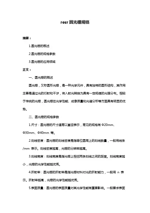
resr圆光栅规格摘要:1.圆光栅的概述2.圆光栅的规格参数3.圆光栅的应用领域正文:一、圆光栅的概述圆光栅,又称圆形光栅,是一种光学元件,具有独特的圆形结构,其作用主要是通过光的衍射和干涉,将入射光转换为具有一定规律的光强分布。
相较于传统的光栅,圆光栅在光学性能、成像质量和光谱分析等方面具有明显的优势。
二、圆光栅的规格参数1.尺寸:圆光栅的尺寸通常以直径表示,常见的规格有Φ20mm、Φ30mm、Φ40mm 等。
2.刻线密度:圆光栅的刻线密度是指单位圆周上的刻线数量,一般用线条/mm 表示。
刻线密度越高,光栅的分辨率越高。
3.刻线宽度:刻线宽度是指光栅上相邻两条刻线之间的距离。
刻线宽度越小,光栅的光学性能越优秀。
4.折射率:圆光栅的折射率是指光栅材料对光的折射能力,一般用n 表示。
折射率越高,光栅的光学性能越优秀。
5.表面质量:圆光栅的表面质量对其光学性能有重要影响。
一般要求表面光洁度高、无明显划痕、污渍等。
三、圆光栅的应用领域1.光学成像:圆光栅可用于制作光学成像系统,提供高质量的成像效果。
2.光谱分析:圆光栅具有较高的分辨率和光谱分析能力,可用于光谱分析仪器中。
3.光学测量:圆光栅可用于测量光的波长、角度等参数。
4.生物医学:圆光栅可用于生物医学领域的成像和光谱分析等。
5.通信技术:圆光栅在光通信领域也有广泛应用,如光纤通信、光开关等。
综上所述,圆光栅作为一种重要的光学元件,在多个领域发挥着重要作用。
其规格参数主要包括尺寸、刻线密度、刻线宽度、折射率和表面质量等,这些参数影响着光栅的光学性能和应用效果。
alpha尺寸等级Alpha尺寸等级Alpha尺寸等级是指材料的表面粗糙度等级,用于描述材料表面的光洁度和光滑度。
Alpha尺寸等级通常用字母A表示,分为A0、A1、A2、A3、A4等级,其中A0级最光滑,A4级最粗糙。
A0级表面光滑度极高,适用于对表面要求非常高的产品,如光学元件、精密仪器等。
这种等级的材料表面几乎没有明显的瑕疵和缺陷,可以实现非常高的光线反射率和透射率。
A1级表面光滑度较高,适用于对表面要求较高的产品,如电子设备、汽车零部件等。
这种等级的材料表面可能存在少量的微小瑕疵,但对产品的性能影响较小。
A2级表面光滑度一般,适用于一般要求的产品,如家电、日用品等。
这种等级的材料表面可能存在一些明显的瑕疵,但通常不会影响产品的正常使用。
A3级表面光滑度较差,适用于对表面要求不高的产品,如建筑材料、包装材料等。
这种等级的材料表面可能存在较多的瑕疵,但不会影响产品的基本功能。
A4级表面粗糙度较高,适用于对表面要求较低的产品,如辅助工具、一次性用品等。
这种等级的材料表面可能存在很多瑕疵,但通常不会影响产品的使用寿命和安全性。
Alpha尺寸等级的确定通常通过目测或使用专业仪器进行测量。
在生产过程中,根据产品的具体要求和应用场景,选择合适的尺寸等级是非常重要的。
不同等级的材料适用于不同的产品,选择合适的尺寸等级可以降低生产成本,提高产品质量和市场竞争力。
除了Alpha尺寸等级外,还有其他一些常用的表面粗糙度等级,如Ra、Rz等。
这些等级也是用于描述材料表面的光洁度和光滑度,但具体的测量方法和标准可能有所不同。
在实际应用中,根据具体情况选择合适的表面粗糙度等级是非常重要的。
Alpha尺寸等级是描述材料表面粗糙度的重要指标,对于不同的产品和应用场景,选择合适的尺寸等级可以提高产品的质量和性能。
在生产过程中,通过控制和管理尺寸等级,可以降低生产成本,提高产品的市场竞争力。
因此,对于生产厂家和消费者来说,了解和理解Alpha尺寸等级的意义和应用是非常重要的。
What is an optic surface figure Filed under: choose your optics — Tags: compare how to choose my optics Marechal criterion MIL-O-13830 peak-to-valley peak-to-valley vs RMS scratch-dig stray light Strehl ratio surface figure surface quality — Webmaster7:58 pm The surface figure or surface quality or surface cosmetics all refer to the deviation between an actual optic and its ideal surface. There are basically two set of information that are commonly given by manufacturers: the surface flatness and what is referred to as “scratch-dig”. Why is it important Well an optic with a bad rating on surface flatness will introduce some wavefront distortions which are responsible for aberrations and bad quality focus. Aberrated wavefront leads to poor Strehl ratio ratio of the observed peak intensity at the image plane compared to the theoretical maximum peak intensity of a perfect optical system so poor optics makes one loose valuable optical power at focus. Plus scratches or digs on an optic create diffraction and stray light which no one wants either. Surface flatness This is the measurement of the difference between the actual surface of the optic and the surface it would have if it was defect-free. There are two main way to measure it the most common is called “peak-to-valley” P-V. This is the difference between the “highest” and “lowest” parts on the surface of the optic those “top” and “bottom” being defined as the local difference between the actual optic and the ideal one. Of course this ignores the curvature of the optics which is not a defect. We consider this method of measuring defects on optic as inaccurate and misleading: it is a maximum measurement and it does not say how many peaks and valley there are on the whole surface. Consequently it is difficult to predict how an optic will perform with this sort of measurement. An optical system having a large P-V error may actually perform better than a system having a small P-V error. Unfortunately it is by far the most widespread flatness quality control in the industry. A much better measurement is the RMS Root Mean Square value of the flatness. This technique involves measuring a substantial amount of the optic’s surface at many points and then calculating the standard deviation of the surface from the ideal form. This measurement has direct mathematical implications: for instance it is possible to calculate the Strehl ratio from it. Once again in short the Strehl ratio is a very good indication on how much power you get at the image plane of the optical system versus what power you will get from an ideal aberration-free system. Once the Strehl ratio has been calculated the quality of the optical system may be ascertained using the Maréchal criterion. The Maréchal criterion states that a system is regarded as well corrected if the Strehl ratio is greater than or equal to 0.8 which corresponds to an rms wavefront error λ/14. For instance an optical system introducing a λ/3 RMS deformation will have his actual power at focus reduced to approximately 3 of its theoretical power. The reason for this drop in power at the focus is that some interferences are created in the focus with different rays arriving with a different phase. Since most manufacturers are specifying their optics flatness in peak-to-valley here is a short comparison of what one should expect. This is without guarantee: as explained above peak-to-valley is imprecise and misleading. surface flatness peat-to-valley quality applications less than λ/2 very low non critical divergent applications only λ/4 low Often best standard for cube beam splitter. Not suitable for high power applications or when wavefront control is important λ/10 good General standard for quality manufacturer. Suitable for most laser and scientific applicati on. λ/20 very good Manufacturers who specify surface flatness in peak-to-valley advise this flatness for critical wavefront control applications such as interferometry or intense femto-second lasers. But honestly ifthis is your case you wouldn’t want to l eave room for imprecision and you would choose a manufacturer able to specify the RMS flatness. Scratch-dig This is yet another very subjective quality measurement. Scratch-dig sometimes called surface quality relates to the number and apparent size of visible defects typically scratches and pits called digs on the part surface. While this may seem straightforward probably no optical specification causes greater confusion. The problem arises because the assessment of scratches and digs is performed using a purely visual non-quantitative comparison to a set of standards which conform to the US military specification MIL-O-13830. This situation arose because the specification was developed many years before the advent of the laser when surface quality was primarily a cosmetic consideration without performance information. Scratch-dig is specified by two numbers such as 40-20. The first number is the maximum width allowance for a scratch measured in microns and the second is the maximum diameter for a dig in hundredths of a milimetre. So 40-20 would permit a scratch width of 0.04mm and a dig diameter of 0.2mm This measurement is obviously badly limited: not only does it entirely rely on a visual inspection but there is no measure of irregularities depth and scratches length nor of their number nor of their position centre being worse. The problem is that this measurement has the potential to give important information on the optic. Small size defects are responsible light scattering loss of contrast and stray light which can damage sensitive components in high power applications. A much better measurement would be the Fourier transform of the surface of the optic if this were available from manufacturers. Once again to help people getting an idea of what they are getting here is a comparison of the average scratch-dig quality from quality manufacturers. Just keep in mind how imprecise this measurement is though. scratch-dig quality applications 60-40 Very low Commercial grade non-critical applications. Also used in low power laser and imaging applications where scattered light is not as critical as costs. 40-20 Low Standard scientific research applications for laser or imaging applications with focused beam that tolerate little scattered light. 20-10 Moderate Laser mirrors and extra-cavity optics. For laser and imaging application with focused beams where minimising scattered light is important. This is the best quality offered by some manufacturer. 10-5 High Intra-cavity laser optics high power applications. Rating: 8.5/10 4 votes cast Share and Enjoy: 引用美军标关于光学表面疵病的说明Link - Thu 16 Oct 2008 09:30:01 0800 Description: 引用pitter_li 的美军标关于光学表面疵病的说明一.定义表面缺陷标准依据美国军用标准MIL-PRF-13830B用两组数字表示表面缺陷大小。


光面通止规φ17±0.2-概述说明以及解释1.引言1.1 概述概述部分:光面通止规φ17±0.2是一种用于测量物体表面平整度和光洁度的工具。
在工程领域中,表面的质量对产品的功能和外观起着至关重要的作用。
光面通止规通过检测表面的平整度和光洁度,可以帮助工程师和制造商确保产品的质量达到要求。
光面通止规的设计精密且简便易用,能够快速准确地测量表面的平整度和光洁度。
其规定的测量标准(φ17±0.2)为工程师提供了一个标准化的参考值,帮助他们评估产品表面的质量,并进行必要的调整和改进。
本文将详细介绍光面通止规的定义、特点和应用,旨在帮助读者更深入地了解该工具的重要性和作用。
同时,我们也将展望光面通止规在未来的发展前景,以期推动其在工程领域的广泛应用和进步。
1.2 文章结构本文主要分为三个部分:引言、正文和结论。
在引言部分,我们将概述光面通止规φ17±0.2的背景和意义,介绍文章的结构以及阐明本文的目的。
在正文部分,我们将详细探讨光面通止规的定义、特点和应用。
通过对光面通止规的相关知识进行系统性的阐述,使读者更加深入地了解该概念。
在结论部分,我们将总结光面通止规的重要性,展望其发展前景,并对全文进行总结和归纳,强调该规范的价值和意义。
1.3 目的本文的目的在于探讨光面通止规φ17±0.2在工程实践中的重要性和应用。
通过对光面通止规的定义、特点和应用进行深入分析,旨在帮助读者更全面地了解这一工具在制造和测量领域的作用。
同时,本文还将总结光面通止规在工程中的重要性,并展望其未来的发展方向。
通过本文的阐述,希望能够为相关领域的专业人士和从业者提供参考,进一步推动光面通止规技术的发展和应用。
2.正文2.1 光面通止规的定义光面通止规是一种用于测量光学元件表面平整度的仪器。
它通过检测光在元件表面的反射情况,来确定表面的平整程度。
光面通止规通常采用干涉法或衍射法来测量元件表面的平整度,精度高,适用于对表面要求极高的光学元件的检测。