4H2094;4H2099;4H2104;4H2105;中文规格书,Datasheet资料
- 格式:pdf
- 大小:179.29 KB
- 文档页数:3
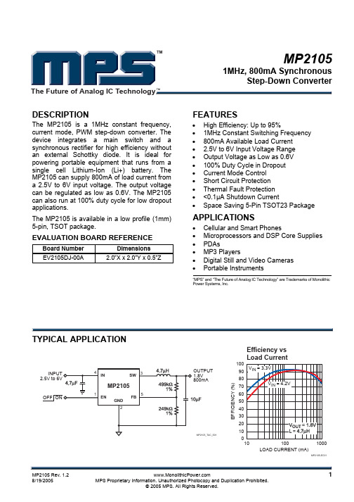
MP21051MHz, 800mA Synchronous Step-Down ConverterThe Future of Analog IC TechnologyTMTMDESCRIPTIONThe MP2105 is a 1MHz constant frequency,current mode, PWM step-down converter. The device integrates a main switch and a synchronous rectifier for high efficiency without an external Schottky diode. It is ideal for powering portable equipment that runs from a single cell Lithium-Ion (Li+) battery. The MP2105 can supply 800mA of load current from a 2.5V to 6V input voltage. The output voltage can be regulated as low as 0.6V. The MP2105 can also run at 100% duty cycle for low dropout applications.The MP2105 is available in a low profile (1mm) 5-pin, TSOT package.EVALUATION BOARD REFERENCEBoard Number Dimensions EV2105DJ-00A2.0”X x 2.0”Y x 0.5”ZFEATURES• High Efficiency: Up to 95%• 1MHz Constant Switching Frequency • 800mA Available Load Current • 2.5V to 6V Input Voltage Range • Output Voltage as Low as 0.6V • 100% Duty Cycle in Dropout • Current Mode Control • Short Circuit Protection • Thermal Fault Protection • <0.1µA Shutdown Current•Space Saving 5-Pin TSOT23 PackageAPPLICATIONS• Cellular and Smart Phones• Microprocessors and DSP Core Supplies • PDAs • MP3 Players• Digital Still and Video Cameras • Portable Instruments“MPS” and “The Future of Analog IC Technology” are Trademarks of Monolithic Power Systems, Inc.TYPICAL APPLICATIONE F F I C I E N C Y (%)101001000LOAD CURRENT (mA)MP2105-EC01Efficiency vs Load CurrentMP2105 – 1MHz 800mA SYNCHRONOUS STEP-DOWN CONVERTER TMPACKAGE REFERENCE* For Tape & Reel, add suffix –Z (eg. MP2105DJ–Z)For Lead Free, add suffix –LF (eg. MP2105DJ–LF–Z) ABSOLUTE MAXIMUM RATINGS (1) V IN to GND..................................–0.3V to +6.5V V SW to GND...........................–0.3V to V IN +0.3V V FB, V EN to GND..........................–0.3V to +6.5V Junction Temperature.............................+150°C Lead Temperature..................................+260°C Storage Temperature .............–65°C to +150°C Recommended Operating Conditions (2) Supply Voltage V IN.............................2.5V to 6V Output Voltage V OUT..........................0.6V to 6V Operating Temperature.............–40°C to +85°C Thermal Resistance (3)θJA θJCTSOT23-5..............................220....110..°C/W Notes:1) Exceeding these ratings may damage the device.2) The device is not guaranteed to function outside of itsoperating conditions.3) Measured on approximately 1” square of 1 oz copper.ELECTRICAL CHARACTERISTICS (4)V IN = V EN = 3.6V, T A = +25°C, unless otherwise noted.Parameter SymbolCondition MinTypMaxUnits Supply Current V EN = V IN, V FB = 0.65V 440 600 µAShutdown Current V EN = 0V, V IN = 6V 0.10 1 µAIN Undervoltage Lockout Threshold RisingEdge 2.15 2.30 2.40 VIN Undervoltage LockoutHysteresis55 mVT A = +25°C 0.588 0.600 0.612Regulated FB Voltage V FB–40°C ≤ T A≤ +85°C 0.582 0.600 0.618VFB Input Bias Current V FB = 0.65V –50 0.5 +50 nA PFET On Resistance I SW100mA 0.42 ΩNFET On Resistance I SW–100mA 0.26 ΩSW Leakage Current V EN = 0V, V IN = 6V,V SW = 0V or 6V–1 +1 µAPFET Current Limit Duty Cycle = 100%,Current Pulse Width < 1ms1.2 1.62.1 AOscillator Frequency f OSC0.85 1.05 1.25 MHz Thermal Shutdown TripThreshold145 °CEN Trip Threshold –40°C ≤ T A≤+85°C 0.3 0.96 1.5 V EN Input Current V EN = 0V to 6V –1 +1 µA Notes:4) 100% production test at +25°C. Specifications over the temperature range are guaranteed by design and characterization.MP2105 – 1MHz 800mA SYNCHRONOUS STEP-DOWN CONVERTERTMTYPCIAL PERFORMANCE CHARACTERISTICSV IN = 3.3V, V OUT = 1.8V, L1 = 4.7µH, C1 = 4.7µF, C3 = 10µF, T A = +25°C, unless otherwise noted.MP2105-TPC03Load Transient(I OUT =0mA to 500mA step)Light Load Operation(IOUT =0mA)F E E D B AC K V O L T A G E (V )-40+200-20+40+60+80+100-40+200-20+40+60+80+100TEMPERATURE (°C)MP2105-TPC01E F F I C I E N C Y (%)MP2105-TPC04TEMPERATURE (°C)MP2105-TPC02V OUT 100mV/div.I OUT 0.5A/div.V OUT 10mV/div.I L0.2A/div.SW 2V/div.MP2105 – 1MHz 800mA SYNCHRONOUS STEP-DOWN CONVERTERTMTYPCIAL PERFORMANCE CHARACTERISTICS (continued)V IN = 3.3V, V OUT = 1.8V, L1 = 4.7µH, C1 = 4.7µF, C3 = 10µF, T A = +25°C, unless otherwise noted.MP2105-TPC09Short Circuit Protection(No Load)MP2105-TPC07Heavy Load OperationI OUT= 800mAMP2105-TPC10Short Circuit Recovery (No Load)MP2105-TPC08Startup from ShutdownV OUT 10mV/div.I L0.2A/div.L =0SW 2V/div.V OUT 1V/div.I L0.5A/div.V OUT 1V/div.I L0.5A/div.V EN 2V/div.V OUT 1V/div.I L0.5A/div.PIN FUNCTIONSPin # Name DescriptionEN 1Regulator Enable Control Input. Drive EN above 1.5V to turn on the MP2105. Drive EN below0.3V to turn it off (shutdown current < 0.1µA).GND 2 Ground SW 3 Power Switch Output. Inductor connection to drains of the internal PFET and NFET switches. IN 4 Supply Input. Bypass to GND with a 2.2µF or greater ceramic capacitor.FB 5Feedback Input. Connect FB to the center point of the external resistor divider. The feedbackthreshold voltage is 0.6V.MP2105 – 1MHz 800mA SYNCHRONOUS STEP-DOWN CONVERTERTMOPERATIONThe MP2105 is a constant frequency current mode PWM step-down converter. The MP2105 is optimized for low voltage, Li-Ion battery powered applications where high efficiency and small size are critical. The MP2105 uses an external resistor divider to set the output voltage from 0.6V to 6V. The device integrates both a main switch and a synchronous rectifier, which provides high efficiency and eliminatesan external Schottky diode. The MP2105 can achieve 100% duty cycle. The duty cycle D of a step-down converter is defined as:%100V V %100f T D INOUTOSC ON ×≈××= where T ON is the main switch on time, and f OSC is the oscillator frequency (1MHz).INENFBGNDSWMP2105_BD01Figure 1—Functional Block DiagramMP2105 – 1MHz 800mA SYNCHRONOUS STEP-DOWN CONVERTERTMCurrent Mode PWM ControlSlope compensated current mode PWM control provides stable switching and cycle-by-cycle current limit for superior load and line response and protection of the internal main switch and synchronous rectifier. The MP2105 switches at a constant frequency (1MHz) and regulates the output voltage. During each cycle the PWM comparator modulates the power transferred to the load by changing the inductor peak current based on the feedback error voltage. During normal operation, the main switch is turned on for a certain time to ramp the inductor current at each rising edge of the internal oscillator, and switched off when the peak inductor current is above the error voltage. When the main switch is off, the synchronous rectifier will be turned on immediately and stay on until either the next cycle starts. Dropout OperationThe MP2105 allows the main switch to remain on for more than one switching cycle and increases the duty cycle while the input voltage is dropping close to the output voltage. When the duty cycle reaches 100%, the main switch is held on continuously to deliver current to the output up tothe PFET current limit. The output voltage then is the input voltage minus the voltage drop across the main switch and the inductor.Short Circuit ProtectionThe MP2105 has short circuit protection. When the output is shorted to ground, the oscillator frequency is reduced to prevent the inductor current from increasing beyond the PFET current limit. The PFET current limit is also reduced to lower the short circuit current. The frequency and current limit will return to the normal values once the short circuit condition is removed and the feedback voltage reaches 0.6V.Maximum Load CurrentThe MP2105 can operate down to 2.5V input voltage; however the maximum load current decreases at lower input due to large IR drop on the main switch and synchronous rectifier. The slope compensation signal reduces the peak inductor current as a function of the duty cycle to prevent sub-harmonic oscillations at duty cycles greater than 50%. Conversely the current limit increases as the duty cycle decreases.APPLICATION INFORMATIONOutput Voltage SettingThe external resistor divider sets the output voltage (see Figure 3). The feedback resistor R1 also sets the feedback loop bandwidth with the internal compensation capacitor (see Figure 1). Choose R1 around 500k Ω for optimal transient response. R2 is then given by:1V6.0V 1R 2R OUT−=Table 1—Resistor Selection vs. OutputVoltage SettingV OUT R1 R2 1.2V 499k Ω (1%) 499k Ω (1%) 1.5V 499k Ω (1%) 332k Ω (1%) 1.8V 499k Ω (1%) 249k Ω (1%) 2.5V499k Ω (1%)158k Ω (1%)Inductor SelectionA 1µH to 10µH inductor with DC current rating at least 25% higher than the maximum load current is recommended for most applications. For best efficiency, the inductor DC resistance shall be <200m Ω. See Table 2 for recommended inductors and manufacturers. For most designs, the inductance value can be derived from the following equation:()OSCL IN OUT IN OUT f I V V V V L ×∆×−×=where ∆I L is Inductor Ripple Current. Choose inductor ripple current approximately 30% of the maximum load current, 800mA.The maximum inductor peak current is:2I I I LLOAD )MAX (L ∆+= Under light load conditions below 100mA, larger inductance is recommended for improved efficiency. Table 3 lists inductors recommended for this purpose.MP2105 – 1MHz 800mA SYNCHRONOUS STEP-DOWN CONVERTERTMTable 2—Suggested Surface Mount InductorsManufacturerPart NumberInductance (µH)Max DCR (Ω)Saturation Current (A)Dimensions LxWxH (mm 3)Coilcraft D01605T-472 4.70.150 1.20 5.4x4.2x1.8 Toko D52LC 4.7 0.087 1.14 5x5x2 Sumida CR43-4R7 4.7 0.109 1.15 4.3x4.8x3.5Table 3—Inductors for Improved Efficiency at 25mA, 50mA, under 100mA Load.ManufacturerPart NumberInductance (µH)Max DCR (Ω)Saturation Current (A)I RMS (A)Coilcraft DO1605T-103MX 100.3 1.0 0.9 Murata LQH4C100K04 10 0.2 1.2 0.8 Sumida CR32-100 10 0.2 1.0 0.7 Sumida CR54-100 100.1 1.21.4Input Capacitor SelectionThe input capacitor reduces the surge current drawn from the input and switching noise from the device. The input capacitor impedance at the switching frequency shall be less than input source impedance to prevent high frequency switching current passing to the input. Ceramic capacitors with X5R or X7R dielectrics are highly recommended because of their low ESR and small temperature coefficients. For most applications, a 4.7µF capacitor is sufficient. Output Capacitor SelectionThe output capacitor keeps output voltage ripple small and ensures regulation loop stable. The output capacitor impedance shall be low at the switching frequency. Ceramic capacitors with X5R or X7R dielectrics are recommended. The output ripple ∆VOUT is approximately:()⎟⎟⎠⎞⎜⎜⎝⎛××+×××−×≤∆3C f 81ESR L f V V V V V OSC OSC IN OUT IN OUT OUTPC Board LayoutThe high current paths (GND, IN and SW)should be placed very close to the device with short, direct and wide traces. Input capacitor C1 needs to be as close as possible to the IN and GND pins. The external feedback resistors shall be placed next to the FB pin. Keep the switching node SW short and away from the feedback network. Figure 2 illustrates an example of PCB layout and signal routing.Figure 2—MP2105 Suggested LayoutMP2105 – 1MHz 800mA SYNCHRONOUS STEP-DOWN CONVERTERNOTICE: The information in this document is subject to change without notice. Please contact MPS for current specifications. Users should warrant and guarantee that third party Intellectual Property rights are not infringed upon when integrating MPS products into any application. MPS will not assume any legal responsibility for any said applications.TMPACKAGE INFORMATIONTSOT23-5Gauge Plane0.25 BSC.±0.10-+0.4000°0°4°(2 plcs)10°TYP.2.90 BSC(5PLCS)0.300(Min)LC TYP .0.950LC TYP .0.9502.80 B S C1.60 B S C330.500(Max)SEATING PLANE0.87±0.030.00-0.101.00M a x .(2 plcs)。

LMC6009LMC6009 9 Channel Buffer Amplifier for TFT-LCDLiterature Number: SNOS786ALMC60099Channel Buffer Amplifier for TFT-LCDGeneral DescriptionThe LMC6009is a CMOS integrated circuit that buffers 9reference voltages for gamma correction in a Thin Film Transistor Liquid Crystal Display (TFT-LCD).Guaranteed to operate at both 3.3V and 5V supplies,this integrated circuit contains nine,independent unity gain buffers that can source 130mA into a capacitive load without oscillation.The LMC6009is useful for buffering gamma voltages into column drivers that employ the resistor-divider architecture.High output current capability and fast settling characteristics of this device improve display quality by minimizing rise time errors at the outputs of the column driver.The integration of nine buffers and a multiplexer eliminates the need for dis-crete buffers and a separate multiplexer (MUX)chip on the panel.The LMC6009is available in 48-pin surface mount TSSOP .Featuresn Number of inputs18n 3.3V and 5V operation n Supply current 3.5mA n Settling time3µsn A/B channel inputs for asymmetrical Gamma n Number of outputs9n Number of control inputs1nBuilt-in thermal shutdown protectionApplicationsn VGA/SVGA TFT-LCD drive circuits n Electronic Notebooks n Electronic Gamesn Personal Communication Devices nPersonal Digital Assistants (PDA)Application in VGA/SVGA TFT-LCDOrdering InformationPackage Temperature Range Transport MediaNSC Drawing48-pin TSSOP−20˚C–+75˚C MTD48LMC6009MT LMC6009MTXTape and Reel DS012533-1©2001National Semiconductor Corporation please contact the National Semiconductor Sales Office/ Distributors for availability and specifications.ESD Tolerance 1.0kV Input Voltage GND–0.3V≤V+≤V DD+0.3V DC Supply Voltage(V DD)−0.3to+6.5V DC Operating Temperature−20˚C to+75˚C Storage Temperature Range−55˚C to+150˚C Operating Ratings(Note1)Supply Voltage 2.7V≤V DD Frequency DC Thermal Resistance(θJA)Derating8.703V DC Electrical CharacteristicsUnless otherwise specified,all limits are guaranteed for T J=25˚C,and V DD=3.0V DC.Symbol Parameter Conditions Min Typ Max V DD Supply Voltage 2.7 3.0 3.3 V OS Offset Voltage R S=10k20 I B Input Bias Current1500V OL Output Voltage,Low Amp A8and A9I SINK=13mA GND+ 0.2Amp A1–A7 I SINK=13mA GND+ 0.6V OH Output Voltage,High Amp A1and A2I SOURCE=13mAV DD–0.2Amp A3–A9I SOURCE=13mAV DD–0.6I SC Output Short Circuit Current V OUT-1.65V(Note1)80150I DD Supply Current No Load 3.55∆V L Load Regulation V IN=0.3–3V DCI SOURCE=13mA−10I SINK=13mA+10 V IH A/B Switch Logic Voltage,High Select A2V IL A/B Switch Logic Voltage,Low Select B0.8 I IH A/B Switch Logic Current,High 1.5 I IL A/B Switch Logic Current,Low1 A V Voltage Gain0.985Note1:See Test Circuit(Figure2)5V DC Electrical CharacteristicsUnless otherwise specified,all limits are guaranteed for T J=25˚C,and V DD=5V DC.Symbol Parameter Conditions Min Typ Max V DD Supply Voltage 4.55 5.5 V OS Offset Voltage R S=10k20 I B Input Bias Current1500V OL Output Voltage,Low Amp A8and A9I SINK=20mA GND+ 0.2Amp A1–A7 I SINK=20mA GND+ 1.0V OH Output Voltage,High Amp A1and A2I SOURCE=20mAV DD–0.2Amp A3–A9I SOURCE=20mAV DD–1.0I SC Output Short Circuit Current V OUT-1.65V(Note1)120200I DD Supply Current No Load 4.56 L2J DD DCSymbol Parameter Conditions Min Typ Max Units ∆V L Load Regulation V IN=0.5–4.5V DC−10mVI SOURCE=20mAI SINK=20mA+10mVV IH A/B Switch Logic Voltage,High Select A2VV IL A/B Switch Logic Voltage,Low Select B0.8VI IH A/B Switch Logic Current,High 1.5µAI IL A/B Switch Logic Current,Low1µAA V Voltage Gain0.985V/V AC Electrical CharacteristicsUnless otherwise specified,all limits are guaranteed for T J=25˚C,and V DD=3V DC.Symbol Parameter Conditions Min Typ Max Units T S1Settling Time1(Note2)I DC=13mA(Sink/Source)36µsT S2Settling Time2(Note2)I DC=13mA(Sink/Source)36µs Note2:See test circuits(Figure3,Figure4and Figure5)DS012533-2FIGURE1.Rise and Fall Times at Outputs3Description of Pins;LMC6009Pin 1NC Pin 25NC Pin 2NC Pin 26NC Pin 3NC Pin 27NC Pin 4A1in (A)Pin 28NC Pin 5A1in (B)Pin 29A/B Switch Pin 6A2in (A)Pin 30V DD (C)Pin 7A2in (B)Pin 31GND (C)Pin 8A3in (A)Pin 32A9out Pin 9A3in (B)Pin 33A8out Pin 10A4in (A)Pin 34A7out Pin 11A4in (B)Pin 35A6out Pin 12A5in (A)Pin 36A5out Pin 13A5in (B)Pin 37GND (B)Pin 14A6in (A)Pin 38V DD (B)Pin 15A6in (B)Pin 39A4out Pin 16A7in (A)Pin 40A3out Pin 17A7in (B)Pin 41A2out Pin 18A8in (A)Pin 42A1out Pin 19A8in (B)Pin 43GND (A)Pin 20A9in (A)Pin 44V DD (A)Pin 21A9in (B)Pin 45NC Pin 22NC Pin 46NC Pin 23NC Pin 47NC Pin 24NCPin 48NCDS012533-3FIGURE 2.DS012533-4FIGURE 3.A1:13mA Source onlyA2–A4:13mA Sink/SourceDS012FIGURE 4.13mA Sink/SourceDS012FIGURE 5.A6–A8:13mA Sink/SourceA9:13mA Sink OnlyL 4ApplicationsThe LMC6009is useful for buffering the nine reference voltages for gamma correction in a TFT-LCD as shown in Figure7.The A/B channel inputs allow the user to alternate two sets of gamma references to compensate for asymmetri-cal Gamma characteristic during Row Inversion.The LMC6009eliminates the need for nine external switches or an18-to-9multiplexer.Since the buffers in the LMC6009draw extremely low bias current(1.5µA max),large resistance values can be used in the reference voltage string.This allows the power dissipa-tion in the gamma reference circuit to be minimized.The nine buffers are guaranteed to deliver80mA to the load, allowing the pixel voltages of the TFT-LCD to settle very quickly.DS012533-8FIGURE6.Block Diagram of LMC6009 5Example:Below is a calculation of pixel charge time(for a black to black transition)in a VGA display operating at a vertical refresh rate of60Hz,with a panel capacitance of 50pF per sub-pixel:A full black to black transition represents the maximum charging time for the panel,since it requires that the panel capacitance be driven by a4V swing from node V REF1 (Figure7).Total capacitive load presented to the LMC6009isC L=50pF x3x640=96nFOutput current of the LMC6009is:I SC=80mAHence,slew time t SLEW=(96nF x4V)/80mA=3.07µs The total line time for a VGA system is approximately34µs. Therefore,the LMC6009easily meets the drive require-ments for the application.The input resistance seen between the V REFn and V REF(n+1)inputs,(where n=0thru8)of the Column Driver(Figure7)also draw current fro LMC6009.Thus,the actual current available for charg panel capacitance is:Ipx=80mA-(V VREF1–V VREF2)/R CDwhereV V REFn=Voltage at node V REFn,V VREF(n+1)=Voltage at node V REF(n+1),andR CD=Column driver input resistance between VREFn and VREF(n+1)Since the LMC6009is capable of sourcing80mA,th charging time is primarily limited only by the length R CD.C L time constant.To implement a high quality d column drivers that allow the shortest possible time co (lower values of R CD)are desirable.However,lower of R CD result in increased system quiescent power d tion.It is therefore important to optimize system perfor by carefully considering speed vs power tradeoffs.DS012533-7FIGURE7. L6LIFE SUPPORT POLICYNATIONAL’S PRODUCTS ARE NOT AUTHORIZED FOR USE AS CRITICAL COMPONENTS IN LIFE SUPPORT DEVICES OR SYSTEMS WITHOUT THE EXPRESS WRITTEN APPROVAL OF THE PRESIDENT AND GENERAL COUNSEL OF NATIONAL SEMICONDUCTOR CORPORATION.As used herein:1.Life support devices or systems are devices or systems which,(a)are intended for surgical implant into the body,or (b)support or sustain life,and whose failure to perform when properly used in accordance with instructions for use provided in the labeling,can be reasonably expected to result in a significant injury to the user.2.A critical component is any component of a life support device or system whose failure to perform can be reasonably expected to cause the failure of the life support device or system,or to affect its safety or effectiveness.National Semiconductor Corporation AmericasTel:1-800-272-9959Fax:1-800-737-7018Email:support@National Semiconductor EuropeFax:+49(0)180-5308586Email:europe.support@Deutsch Tel:+49(0)6995086208English Tel:+44(0)8702402171Français Tel:+33(0)141918790National Semiconductor Asia Pacific Customer Response Group Tel:65-2544466Fax:65-2504466Email:ap.support@National Semiconductor Japan Ltd.Tel:81-3-5639-7560Fax:81-3-5639-7507All dimensions are in millimeters48-Lead Molded Thin Shrink Small Outline Package,JEDECNS Package Number MTD48National does not assume any responsibility for use of any circuitry described,no circuit patent licenses are implied and National reserves the right at any time without notice to change said circuitry and specifications.IMPORTANT NOTICETexas Instruments Incorporated and its subsidiaries(TI)reserve the right to make corrections,modifications,enhancements,improveme and other changes to its products and services at any time and to discontinue any product or service without notice.Customers should obtain the latest relevant information before placing orders and should verify that such information is current and complete.All products a sold subject to TI’s terms and conditions of sale supplied at the time of order acknowledgment.TI warrants performance of its hardware products to the specifications applicable at the time of sale in accordance with TI’s standard warranty.Testing and other quality control techniques are used to the extent TI deems necessary to support this warranty.Except where mandated by government requirements,testing of all parameters of each product is not necessarily performed.TI assumes no liability for applications assistance or customer product design.Customers are responsible for their products and applications using TI components.To minimize the risks associated with customer products and applications,customers should provide adequate design and operating safeguards.TI does not warrant or represent that any license,either express or implied,is granted under any TI patent right,copyright,mask work rig or other TI intellectual property right relating to any combination,machine,or process in which TI products or services are rma published by TI regarding third-party products or services does not constitute a license from TI to use such products or services or a warranty or endorsement e of such information may require a license from a third party under the patents or other intellectual property of the third party,or a license from TI under the patents or other intellectual property of TI.Reproduction of TI information in TI data books or data sheets is permissible only if reproduction is without alteration and is accompanie by all associated warranties,conditions,limitations,and notices.Reproduction of this information with alteration is an unfair and deceptiv business practice.TI is not responsible or liable for such altered rmation of third parties may be subject to additional restrictions.Resale of TI products or services with statements different from or beyond the parameters stated by TI for that product or service voids a express and any implied warranties for the associated TI product or service and is an unfair and deceptive business practice.TI is not responsible or liable for any such statements.TI products are not authorized for use in safety-critical applications(such as life support)where a failure of the TI product would reasona be expected to cause severe personal injury or death,unless officers of the parties have executed an agreement specifically governing such use.Buyers represent that they have all necessary expertise in the safety and regulatory ramifications of their applications,and acknowledge and agree that they are solely responsible for all legal,regulatory and safety-related requirements concerning their product and any use of TI products in such safety-critical applications,notwithstanding any applications-related information or support that may b provided by TI.Further,Buyers must fully indemnify TI and its representatives against any damages arising out of the use of TI products such safety-critical applications.TI products are neither designed nor intended for use in military/aerospace applications or environments unless the TI products are specifically designated by TI as military-grade or"enhanced plastic."Only products designated by TI as military-grade meet military specifications.Buyers acknowledge and agree that any such use of TI products which TI has not designated as military-grade is solely a the Buyer's risk,and that they are solely responsible for compliance with all legal and regulatory requirements in connection with such us TI products are neither designed nor intended for use in automotive applications or environments unless the specific TI products are designated by TI as compliant with ISO/TS16949requirements.Buyers acknowledge and agree that,if they use any non-designated products in automotive applications,TI will not be responsible for any failure to meet such requirements.Following are URLs where you can obtain information on other Texas Instruments products and application solutions:Products ApplicationsAudio /audio Communications and Telecom /communications Amplifiers Computers and Peripherals /computersData Converters Consumer Electronics /consumer-appsDLP®Products Energy and Lighting /energyDSP Industrial /industrialClocks and Timers /clocks Medical /medicalInterface Security /securityLogic Space,Avionics and Defense /space-avionics-defense Power Mgmt Transportation and Automotive /automotive Microcontrollers Video and Imaging /videoRFID OMAP Mobile Processors /omapWireless Connectivity /wirelessconnectivityTI E2E Community Home Page Mailing Address:Texas Instruments,Post Office Box655303,Dallas,Texas75265Copyright©2011,Texas Instruments Incorporated分销商库存信息: NATIONAL-SEMICONDUCTOR LMC6009MTX。
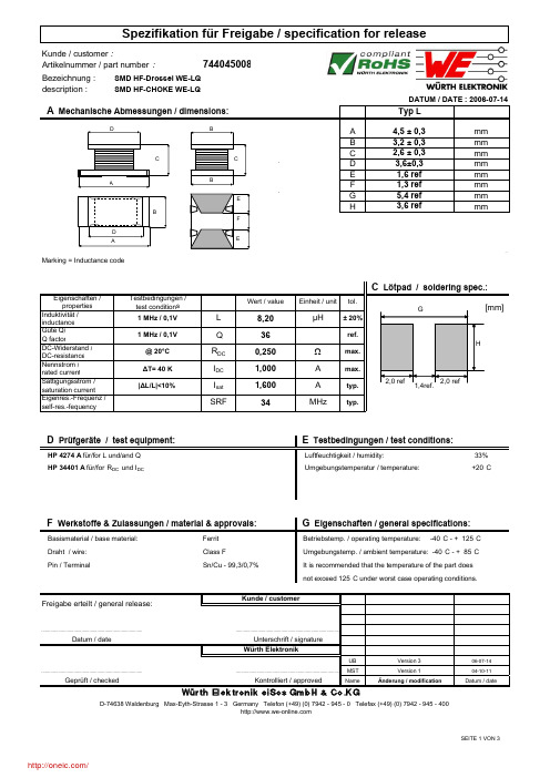
description :Marking = Inductance code33% Umgebungstemperatur / temperature:+20°CFerrit UB06-07-14MST 04-10-11NameDatum / dateÄnderung / modificationVersion 1Version 3..............................................................................................................................................................................................................................................Würth ElektronikHP 4274 A für/for L und/and Q HP 34401 A für/for R DC und I DCD Prüfgeräte / test equipment:SMD HF-CHOKE WE-LQWürth Elektronik eiSos GmbH & Co.KGD-74638 Waldenburg · Max-Eyth-Strasse 1 - 3 · Germany · Telefon (+49) (0) 7942 - 945 - 0 · Telefax (+49) (0) 7942 - 945 - 400Geprüft / checked Umgebungstemp. / ambient temperature: -40°C - + 85°C Basismaterial / base material: Datum / date..............................................................................Unterschrift / signature Kontrolliert / approvednot exceed 125°C under worst case operating conditions.F Werkstoffe & Zulassungen / material & approvals:Draht / wire:Pin / TerminalClass FSn/Cu - 99,3/0,7%G Eigenschaften / general specifications:Betriebstemp. / operating temperature: -40°C - + 125°C Kunde / customerFreigabe erteilt / general release:E Testbedingungen / test conditions:Luftfeuchtigkeit / humidity:It is recommended that the temperature of the part doesdescription :UB06-07-14MST 04-10-11NameDatum / dateÄnderung / modificationVersion 1Version 3Datum / dateUnterschrift / signature Würth Elektronik..............................................................................................................................................................Geprüft / checked Kontrolliert / approvedWürth Elektronik eiSos GmbH & Co.KGD-74638 Waldenburg · Max-Eyth-Strasse 1 - 3 · Germany · Telefon (+49) (0) 7942 - 945 - 0 · Telefax (+49) (0) 7942 - 945 - 400Kunde / customer..............................................................................................................................................................SMD HF-CHOKE WE-LQH Induktivitätskurve / Inductance curve :Freigabe erteilt / general release:DATUM / DATE : 2006-07-14description :I Rollenspezifikation / tape and reel specification:A 8,0± 1,0mm B4,0± 0,1mma 178± 0,5mmb 20,20± 0,1mm+ 0,5- 1,0d 50,0± 1,0mmUB06-07-14MST04-10-11NameDatum / dateÄnderung / modificationVersion 1Version 3mm 13,00c SMD HF-CHOKE WE-LQDATUM / DATE : 2006-07-14Gurtspezifikation / Tape specification: Rollenspezifikation / Reel specification:Freigabe erteilt / general release:Kunde / customer..............................................................................................................................................................Datum / dateUnterschrift / signature Würth Elektronik..............................................................................................................................................................Würth Elektronik eiSos GmbH & Co.KGD-74638 Waldenburg · Max-Eyth-Strasse 1 - 3 · Germany · Telefon (+49) (0) 7942 - 945 - 0 · Telefax (+49) (0) 7942 - 945 - 400Geprüft / checkedKontrolliert / approvedThe force for tearing off cover tape is 20 to 70 grams in arrow directionfeeding directionThis electronic component has been designed and developed for usage in general electronic equipment. Before incorporating this component into any equipment where higher safety and reliability is especially required or if there is the possibility of direct damage or injury to human body, for example in the range of aerospace, aviation, nuclear control, submarine,transportation, (automotive control, train control, ship control), transportation signal, disaster prevention, medical, public information network etc, Würth Elektronik eiSos GmbH must be informed before the design-in stage. In addition, sufficient reliability evaluation checks for safety must be performed on every electronic component which is used in electrical circuits that require high safety and reliability functions or performance分销商库存信息: WURTH-ELECTRONICS 744045008。
Descriptions:1. Delta will not guarantee the performance of the products if the application condition fallsoutside the parameters set forth in the specification.2. A written request should be submitted to Delta prior to approval if deviation from thisspecification is required.3. Please exercise caution when handling fans. Damage may be caused when pressure is appliedto the impeller, if the fans are handled by the lead wires, or if the fans are hard-dropped to the production floor.4. Except as pertains to some special designs, there is no guarantee that the products will be freefrom any such safety problems or failures as caused by the introduction of powder, droplets of water or encroachment of insect into the hub.5. The above-mentioned conditions are representative of some unique examples and viewed as thefirst point of reference prior to all other information.6. It is very important to establish the correct polarity before connecting the fan to the powersource. Positive (+) and Negative (-). Damage may be caused to the fans if connection is with reverse polarity, as there is no foolproof method to protect against such error.7. Delta fans are not suitable where any corrosive fluids are introduced to their environment.8. Please ensure all fans are stored according to the storage temperature limits specified. Do notstore fans in a high humidity environment. We highly recommend performance testing is conducted before shipping, if the fans have been stored over 6 months.9. Not all fans are provided with the Lock Rotor Protection feature. If you impair the rotation ofthe impeller for the fans that do not have this function, the performance of those fans will lead to failure.10. Please be cautious when mounting the fan. Incorrect mounting of fans may cause excessresonance, vibration and subsequent noise.11. It is important to consider safety when testing the fans. A suitable fan guard should be fitted tothe fan to guard against any potential for personal injury.12. Except where specifically stated, all tests are carried out at relative (ambient) temperature andhumidity conditions of 25o C, 65%. The test value is only for fan performance itself.13. Be certain to connect an “over 4.7µF” capacitor to the fan externally when the application callsfor using multiple fans in parallel, to avoid any unstable power./分销商库存信息: DELTA-PRODUCT-GROUPS EFB0405HD。
T E R M I N A L B O A R D S &S T R I P S142Tel (718)956-8900•Fax (718)956-9040(800)221-5510•kec@31-0720th Road –Astoria,NY 11105-2017RoHS COMPLIANT ~ISO 9001CERTIFIED®QUICK-FIT TERMINAL STRIPSA.375[9.5].187[4.8]L .500[12.7].128[3.3] DIA .(2)PLS.062 [1.57]BACKING INSULATOR .031(.79)FIBERA NO.TERM.BACKING STRIPL MTG.EACH CAT.CAT.LENGTHCENTERS SIDENO.NO.1.500(38.1) 1.125(28.6)2411644012.250(57.2) 1.875(47.6)4411744023.000(76.2) 2.625(66.7)6411844033.750(95.3) 3.375(85.7)8411944044.500(114.3) 4.125(104.8)1041204405MATERIAL:Fiberglass -NEMA GRADE GPO-3.A glass polyester rated for continuous operation at 300°F (155°C).062(1.57)Backing Strips:.031(.79)fibre with mounting holes drilled only Terminals:BrassCAT.NO.1257.032(.81)Bright Brass Other platings available on special orderNO.OF L A TERMS CAT.NO.CAT.NO.CAT.NO.CAT.NO.1.125(28.6).750(19.1)1603-1609-1604-1607-11.500(38.1) 1.125(28.6)2603-2609-2604-2607-21.875(47.6) 1.500(38.1)3603-3609-3604-3607-32.250(57.2) 1.875(47.6)4603-4609-4604-4607-42.625(66.7) 2.250(57.2)5603-5609-5604-5607-53.000(76.2) 2.625(66.7)6603-6609-6604-6607-63.375(85.7) 3.000(76.2)7603-7609-7604-7607-73.750(95.3) 3.375(85.7)8603-8609-8604-8607-84.125(104.8) 3.750(95.3)9603-9609-9604-9607-94.500(114.3)4.125(104.8)10603-10609-10604-10607-10NO.OF MATERIAL MATERIAL TERMS PBEGEE W S L EACH SIDE CAT.NO.CAT.NO.2.625(66.7)515101153015.250(133.4)121510215302.500[12.7]Single Row 7.875(200.0)19151031530310.500(266.7)26151041530413.125(333.4)3315105153052.625(66.7)515106153065.250(133.4)1215107153071.188(30.2).750(19.1)7.875(200.0)19151081530810.50(266.7)26151091530913.125(333.4)3315110153102.625(66.7)515111153115.250(133.4)1215112153121.500(38.1)1.000(25.4)7.875(200.0)19151131531310.500(266.7)26151141531413.125(333.4)3315115153152.625(66.7)515116153165.250(133.4)1215117153172.000(50.8)1.500(38.1)7.875(200.0)19151181531810.500(266.7)26151191531913.125(333.4)3315120153202.625(66.7)515121153215.250(133.4)1215122153222.500(63.5)2.000(50.8)7.875(200.0)19151231532310.500(266.7)26151241532413.125(333.4)3315125153252.625(66.7)515126153265.250(133.4)1215127153273.000(76.2)2.500(63.5)7.875(200.0)19151281532810.500(266.7)26151291532913.125(333.4)331513015330BOARDS ON THIS PAGE ARE NOT SCOREDReady-Made Terminal Boards:Low cost,meets commercial and military specifications.Produced in large quantities,making it possible to eliminate tooling and setup charges usually applied to non-standard boards.Terminals are staked in all holes except end mounting holes.Hole thru 1503W S.375[9.5].187[4.8].093 [2.36].120[3.1]DIA.WLA.375[9.5].187[4.8]L .500[12.7].120[3.1]DIA .(2)PLS.093[2.36]Hole thru1503150915451507MATERIAL:Choice of either PBE or GEE.PBE:Paper base electrical,MIL-1-24768/20,Type XP natural,Temp.250°F (121°C)max.GEE:Glass epoxy,MIL-I-24768/27,Type G-10,Temp.300ºF (155°C)max.Terminals:Brass,ASTM-B16.Tin Plate,MIL-T-10727.Other plating can be furnished .MATERIAL:PBEPBE:Paper base electrical,FED.LP-513,Type XP natural,Temp.250°F (121°C)max.Terminals:Brass,ASTM-B16.Tin Plate,MIL-T-10727.Other plating can be furnished .MODIFICATIONSBoards can be modified with other materials or terminals of your choice.Marking can also be added.Quotations upon request..250(6.4)TABS分销商库存信息:KEYSTONE-ELECTRONICS405640574058 40594060603-1 609-1604-1607-1 603-2609-2607-2 603-3607-3604-2 609-3603-4609-4 607-415101603-5 609-5604-3609-6 603-615301607-5 609-7603-7607-6 604-4609-8603-8 609-9603-9607-8 609-10604-5603-10 607-91510615102 15111604-6607-10 607-71511615121 153021********* 604-715126604-8 1531615103604-9 1532115326604-10 153031********* 151041511715122 153071********* 153121531715105 153221532715108 153051511315118 151231512815308 153181531315109 151141511915323 153091512415328 151291********* 153141512015319 151251513015324 153291********* 153201532515330。
www.kodak.com/go/imagers
PRODUCT SUMMARY
KODAK KAC-00401 IMAGE SENSOR
1/3” WVGA RAW CMOS IMAGE SENSOR
DESCRIPTION
The KAC-00401 is a high performance, low power,
automotive grade image sensor capable of capturing
motion and still images. Included on-chip is a video gain
amplifier, 12-bit A/D converter, and fixed pattern noise
elimination circuits. Also integrated are programmable
smart timing and control circuits, which allow maximum
flexibility in adjusting gain, frame rate, integration time,
and active window size. In addition, the dynamic range of
the sensor can be extended >100dB through a high
dynamic range response curve.
FEATURES
WVGA resolution for wider field of view
Monochrome or Bayer RGB available
Low noise architecture for increased SNR
Enhanced near-IR performance
Extended Dynamic Range via three breakpoint
programmable response curve
Partial Line Integration for superior exposure
control under high-light conditions
High frame rate – 52 fps @ full resolution
Simple I
2
C compatible serial interface
Operating temperature range up to +105°C
Automotive grade 48-pin PQFP
APPLICATIONS
Automotive Imaging
Machine Vision
Parameter Value
Optical Format 1/3-inch
Active Array 768(H) x 488(V)
Imaging Area 5.15mm(H) x 3.27mm(V)
Pixel Size 6.7µm x 6.7µm
Quantum Efficiency Monochrome: 60% @ 550nm
Sensitivity Monochrome: 4.5 V/lux-sec
Dynamic Range Linear: 60dB
Extended: >100dB
Dark Current 0.9nA/cm2
Read Noise 4.3 LSBs
Frame Rate 52 fps @ 768H x 488V
Readout Rate 6-24 MSPS
Data Format 12-bit parallel Bayer RAW
Scan Mode Progressive scan
Shutter Modes Continuous and single frame rolling
shutter
Programmable Gain Fine: 5.7x, 0.075x steps
Coarse: 2.35x, 0.19x steps
Power Supply I/O: 3.3V ±10%
Analog: 3.3V ±5%
Digital: 1.8V ±5%
Power Consumption Total: 191mW
Analog + I/O: 184mW
Digital: 7mW
Temperature Range Operating: -40°C to 105°C
Package 48-pin PQFP
All parameters above are specified at T = 20C
©Eastman Kodak Company, 2009. Kodak and Pixelux are trademarks Revision 1.2
ORDERING INFORMATION
Catalog Number Product Name Description
4H2104 KEK-4H2104-KAC-00401 CDU Evaluation Kit – Complete System
4H2105 KEH-4H2105-KAC-00401 CDU Evaluation Kit – Headboard only
4H2094 KAC-00401-MBC-LB-A1 Trays
Monochrome, Telecentric Microlens, PQFP Package in Tray, Clear Cover
Glass, Standard Grade
4H2099 KAC-00401-CBC-LB-A0 Trays
Bayer RGB, Telecentric Microlens, PQFP Package in Tray, Clear Cover Glass,
Standard Grade
Please see ISS Application Note “Product Naming Convention” (MTD/PS-0892) for a full description of naming convention
used for KODAK image sensors.
For all reference documentation, please visit our Web Site at www.kodak.com/go/imagers.
Please address all inquiries and purchase orders to:
Image Sensor Solutions
Eastman Kodak Company
Rochester, New York 14650-2010
Phone: (585) 722-4385
Fax: (585) 477-4947
E-mail: imagers@kodak.com
Kodak reserves the right to change any information contained herein without notice. All information furnished by Kodak is
believed to be accurate.
分销商库存信息:
KODAK
4H20944H20994H2104
4H2105