国巨电阻规格书
- 格式:pdf
- 大小:645.67 KB
- 文档页数:40
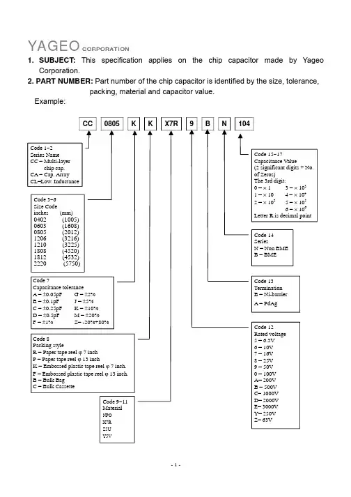
Page-1Approval SheetforCarbon Film ResistorsCFR series±2% & ±5%YAGEO CORPORATIONHeadquarters: 3F, No.233-1, Pao Chiao Rd., Shin Tien, Taipei, Taiwan,R.O.C.Tel: 886-2-2917-7555 Fax: 886-2-2917-4286URL: Page-2Page-31. PRODUCT : CARBON FILM RESISTORS(Normal & Miniature Style)2. PART NUMBER : Part number of the carbon film resistor is identified by the name,power, tolerance, packing, temperature coefficient, special type and resistance value.Example :CFR -12 J T J 52 100RSeries Size Resistance Packing Temperature Special ResistanceName Code Tolerance Style Coefficient Type Value of Resistance(1) Style: CFR SERIES(2) Power Rating: -12=1/6W 、25S=1/4WS 、-25=1/4W 、50S=1/2WS 、-50=1/2W 、 1WS=1WS 、100=1W 、2WS=2WS 、200=2W(3) Tolerance: G=±2% J=±5%(4) Packaging Type : R =Paper Taping Reel T =Tape on Box Packing B =Bulk Packing(5) T .C .R : J=±350ppm/℃ — =lgnore(6) Special Type : 26=26mm 、52=52.4mm 、73=73mm 、 PN =PANAsert AV =AVlsert(7) Resistance Value: 1R 、10R 、100R 、10K 、100K 、330K 、1M………Page-43. BAND-CODE:4. ELECTRICAL CHARACTERISTICSTabe I*Standard resistance is 1Ω~ 10M Ω, below or over this resistance on request. *Rated Continuous Working Voltage (RCWV)=Value Resistance Rating Power ×FIG.1 TEMPERATURE COEFFICIENTPage-55. DERATING CURVE & HOT-SPOT TEMPERATURE6. DIMENSIONS7. ENVIRONMENTAL CHARACTERISTICS(1) Short Time Over Load TestAt 2.5 times of the rated voltage. (If the voltage exceeds the maximum load voltage, the maximum load voltage will be used as the rated voltage) applied for 5 seconds, the resistor should be free from defects after the resistor is released from load for about 30 minutes and the change of the resistance value should be within ±(0.25%+0.05Ω) as compared with the value before the test.Page-6(2) Dielectric Withstanding VoltageThe resistor is placed on the metal V Block. Apply a Table I dielectric withstanding between the terminals connected together with the block for about 60 seconds. The resistor shall be able to withstand without breakdown or flashover.(3) Temperature Coefficient TestTest of resistors above room temperature 125°C to 130°C (Testing Temperature) at the constant temperature silicon plate for over 4 to 5 minutes. Then measure the resistance. The Temperature Coefficient is calculated by the following equation and its value should be within the range of requested.600010t t 1R R R t Coefficien e Temperatur sistor Re ×−×−=R= Resistance value under the testing temperature R 0= Resistance value at the room temperature t = The testing temperature t o = Room temperature(4) Insulation ResistanceApply test terminal on lead and resistor body. The test resistance should be high than 10,000 Mohm.(5) SolderabilityImmerse the specimen into the solder pot at 230±5°C for 5±0.5 seconds. At least 95% solder coverage on the termination.(6) Resistance to SolventThe specimen into the appropriate solvent of Methyleme Chloride condition ofultrasonic machine for 1 minutes. The specimen is no deterioration of coatings and color code.(7) Terminal StrengthDirect Load – Resistors shall be held by one terminal and the load shall be gradually applied in the direction of the longitudinal axis of the resistor unit the applied load reacheds 5 pounds. The load shall be held for 10 seconds. The load of weight shall be ≧2.5kg(24.5N).Page-7(8) Pulse OverloadApply 4 times of rated voltage to the specimen at the 1 second on and 25 seconds off cycle, subjected to voltage application cycles specified in 10000. The change of the resistance value shall be within ±(2%+0.05Ω).(9) Load Life in HumidityPlace the specimen in a test chamber at 40±2°C and 90~95% relative humidity. Apply the rated voltage to the specimen at the 1.5 hours on and 0.5 hour off cycle. The total length of test is 1000 hours. The change of the resistance value shall be within ±(1.5%+0.05Ω).(10) Load Life TestPlaced in the constant temperature chamber of 70±3°C the resistor shall be connected to the lead wire at the point of 25mm. Length with each terminal, the resistors shall be arranged not much effected mutually by the temperature of the resistors and the excessive ventilation shall not be performed, for 90 minutes on and 30 minutes off under this condition the rated D.C. voltage is applied continuously for 1000+48/-0 hours then left at no-load for 1hour, the change of the resistance value measured at this time to the value before the test shall be within ±(1.5%+0.05Ω). There shall be no remarkable change in the appearance and the color code shall be legible after the test.(11) Temperature Cycling TestThe temperature cycle shown in the following table shall be repeated 5 times consecutively. The measurement of the resistance value is done before the first cycle and after ending the fifth cycle, leaving in the room temperature for about 1 hour, the change shall be within ±(1%+0.05Ω). After the test the resistor shall be free from the electrical or mechanical damage.Temperature Cycling Conditions: Step Temperature(°C) Time (minute)1 +25+10 -5 10 to152 -65+0 -3 30 3 +25+10 -5 10 to15 4+150+3 -030Page-8(12) Resistance to Soldering HeatThe terminal lead shall be dipped into the solder pot at 350±10°C for 3±0.5 seconds up to 3 mm. The change of the resistance value shall be within ±(1%+0.05Ω).8. PACKING METHODS Bandolier for Axial leadsThe resistors are supplied on bandolier, either 1000 resistors in ammopack or 5000 resistors on reel.9. TAPE ON REEL PACKING & TAPE ON BOX PACKING10. SPECIAL TYPE (FORMING DIMENSIONS)。
贴片电阻规格、封装、尺寸ChipR Dimensions 、Footprint简述基本结构分类规格、封装、尺寸额定功率及工作电压阻值,标准阻值标识规格书、生产厂家命名方法价格、报价创建时间:2005-12-30 最后修改时间:2006-10-29贴片电阻套件为方便学生、研发人员试验和产品试制,特推出片式电阻系列套件。
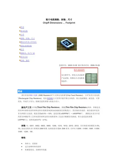
简述我们常说的贴片电阻(SMD Resistor)叫"片式固定电阻器"(Chip Fixed Resistor),又叫"矩形片状电阻"(Rectangular Chip Resistors),是由ROHM公司发明并最早推出市场的。
特点是耐潮湿,耐高温,可靠度高,外观尺寸均匀,精确且温度系数与阻值公差小。
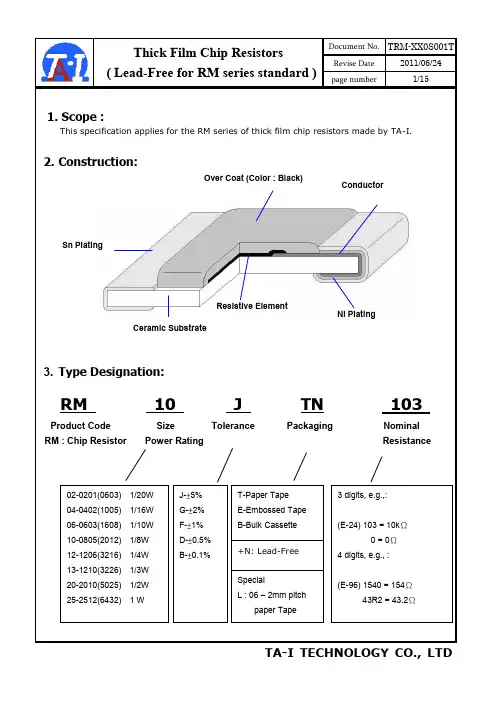
按生产工艺分厚膜(Thick Film Chip Resistors)、薄膜(Thin Film Chip Resistors )两种。
厚膜是采用丝网印刷将电阻性材料淀积在绝缘基体(例如玻璃或氧化铝陶瓷)上,然后烧结形成的。
我们通常所见的多为厚膜片式电阻,精度范围±0.5% ~ 10%,温度系数:±50PPM/℃~ ±400PPM/℃。
薄膜是在真空中采用蒸发和溅射等工艺将电阻性材料淀积在绝缘基体工艺(真空镀膜技术)制成,特点是低温度系数(±5PPM/℃),高精度(±0.01%~±1%)。
封装有:0201,0402,0603,0805,1206,1210,1812,2010,2512。
其常规系列的精度为5%,1%。
阻值范围从0.1欧姆到20M欧姆。
标准阻值有E24,E96系列。
功率有1/20W、1/16W、1/8W、1/10W、1/4W、1/2W、1W。
特性:•体积小,重量轻•适合波峰焊和回流焊•机械强度高,高频特性优越•常用规格价格比传统的引线电阻还便宜•生产成本低,配合自动贴片机,适合现代电子产品规模化生产使用状况:由于价格便宜,生产方便,能大面积减少PCB面积,减少产品外观尺寸,现在已取代绝大部分传统引线电阻。
2005eo.comGenerated: Thu Jan 06 14:30:05 CET 2005; Source: Generated: Thu Jan 06 14:29:15 CET 2005; Source: 1Generated: Thu Jan 06 14:29:18 CET 2005; Source: Note: Value in "Resistance" means the minimum one.Note: Resistance E192; special value on requestNote: TCR=±10ppm/°C; ±15ppm/°C on RequestNote: Tolerance=±0.01%; ±0.05% on RequestNote: Power mode RT0603 on requestGenerated: Thu Jan 06 14:29:34 CET 2005; Source: 3Generated: Thu Jan 06 14:29:41 CET 2005; Source: Note: Value in "Resistance" means the minimum one.Note: TCR=±10ppm/°C; ±15ppm/°C on RequestNote: Tolerance=±0.01%; ±0.05% on RequestGenerated: Thu Jan 06 14:29:49 CET 2005; Source: 5General purpose thin film, 0201-2512Note: Value in "Resistance" means the minimum one.Note: Resistance E192; special value on requestGenerated: Thu Jan 06 14:29:52 CET 2005; Source: Generated: Thu Jan 06 14:29:53 CET 2005; Source: 7Generated: Thu Jan 06 14:29:53 CET 2005; Source: Trimmable, 0805Note: Value in "Resistance" means the minimum one.Arrays, convex and concaveNote: Zero Ohm Jumper<0.05 OhmNote: Value in "Resistance" means the minimum one. Note: 4*0603 (Concave) 1% is on requestNote: 4*1206 (Convex) 1% is on requestNetworkNote: Zero Ohm Jumper<0.05 OhmNote: Value in "Resistance" means the minimum one.Current sensors - Low TCROrdering Information - Single resistor:060307Ordering Information - Array, Network YC164J R0710R L__PaperEmbossedPaperEmbossed02018 mm 10 000---50 000---04028 mm 10 000---50 000---06038 mm 5 000---20 000---08058 mm 5 000---20 000---12068 mm 5 000---20 000---12108 mm 5 000---20 000---121812 mm --- 4 000------201012 mm --- 4 000------251212 mm --- 4 000------YC122 (2x0402)8 mm 10 000---50 000---YC124 (4x0402)8 mm 10 000---40 000---YC/TC16 (4x0603)8 mm 5 000---20 000---YC15 (0616)8 mm 5 000---20 000---YC24 (1220)12 mm 5 000---------YC32/35 (1220/1225)12 mm--- 4 000------Packing QuantitiesSize Code Tape Width 180 mm / 7"330 mm / 13"AsiaYageo Taiwan Tel. +886 (0)2 2917 7555 Fax. +886 (0)2 2917 4286Yageo China, DongguanTel. +86 769 772 0275Fax. +86 769 791 0053Yageo China, SuzhouTel. +86 512 825 5568Fax. +86 512 825 5386Yageo China, BeijingTel. +86 10 851 20810Fax. +86 10 851 20200Yageo Hong Kong Tel. +852 2342 6833Fax. +852 2342 6588Yageo JapanTel. +81 3 5833 3331Fax. +81 3 5833 3116Yageo KoreaTel. +82 31 712 4797Fax. + 82 31 712 5866Yageo Malaysia, PenangTel. +60 4 397 3317Fax. +60 4 397 3272Yageo Malaysia, Kuala LumpurTel. +60 3 5882 2854Fax. +60 3 5882 8700Yageo Singapore Tel. +65-6244 7800Fax. +65-6244 4943EuropeYageo Benelux Tel. +31 475 385 357 Fax. +31 475 385 589Yageo FinlandTel. +358 (0)9 2707 5851Fax. +358 (0)9 2707 5852Yageo FranceTel. +33 1 55 51 84 00Fax. +33 1 55 51 84 24Yageo Germany / CentralEuropeTel. +49 4121 870-0Fax. +49 4121 870-271Yageo Italy / South Europe Tel. +39 02 2411 301Fax. +39 02 2411 3051Yageo UKTel. +44 1372 364500Fax. +44 1372 364567Yageo IberiaTel. +34 93 238 9172Fax. +34 93 415 9951Yageo HungaryTel. +36-30-3777-441Fax. +36-94-517-701Yageo Russia Tel. +7 501 430 96 27 Fax. +7 095 567 02 66Yageo Sweden / NordicTel. +46 8 514 933 55Fax. +46 8 514 933 51Yageo Czech RepublicTel. +420-5-43 23 92 33Fax. +420-5-43 23 92 33North AmericaYageo USA, Seattle Tel. +1 425 492 2818Fax. +1 425 492 2819Yageo USA, Dallas Tel. +1 972 599 0099Fax. +1 972 599 0099。
Approval SheetforThick Film Chip ResistorRL series1% 2% 5%YAGEO CORPORATIONFactory: No.11, Min Chuan Rd., Ta Sheh, Kaohsiung, Taiwan, R.O.C.Tel: 886-7-351-4117 Fax: 886-7-352-6475Headquarters: 3F, No.233-1, Pao Chiao Rd., Hsin Tien, Taipei, Taiwan,R.O.C.Tel: 886-2-2917-7555 Fax: 886-2-2917-4286RL Series Version 2000-3 Page-1RL SeriesVersion 2000-3 Page-21. SUBJECT : This specification describes of RL series chip resistors made of YAGEOCorporation by thick film process.2. PART NUMBER : Part number of the chip resistor is identified by the series, size,tolerance, packing style, temperature coefficient, special type and resistance value.Example :RL 1206 F R - 07 0R02Series Size Resistance Packing Temperature Special ResistanceName Code Tolerance Style Coefficient Type Valueof Resistance(1) Size : (unit: inches)0603=0.063×0.033 1210=0.122×0.102 0805=0.083×0.051 2010=0.197×0.098 1206=0.122×0.0632512=0.250×0.126(2) Tolerance : F=±1%, G=±2%, J=±5%(3) Packaging Style : R =Paper Taping Reel. K =Embossed Plastic Tape Reel. C =Bulk Cassette.(4) T .C .R.: “-“Base on Spec.(5) Special Type : 07= 7 inch Dia. Reel10=10 inch Dia. Reel 13=13 inch Dia. Reel(6) Resistance Value : 10m Ω、20 m Ω、51 m Ω、100 m Ω、330 m Ω、470 m Ω……(7) Resistance Series : E24 (E48/96 on request)RL SeriesVersion 2000-3 Page-33. MARKING :(1) RL0805/RL1206/RL1210/RL2010/RL2512Either tolerance in 5% or 1%: 4 digits, uses MIL Standard resistance marking. “R” signifies decimal place.Value =20m Ω(2) RL0603Tolerance in 5%: 3 digits, uses MIL Standard resistance marking. “R” signifies decimal place.Value =220m Ω1% Tolerance : no marking4. POWER RATING(1) Rated Power at 70°C :RL0603=1/10WRL1210=1/3W RL0805=1/8W RL2012=3/4W RL1206=1/4WRL2512=1W(2) Rated Voltage : The DC or AC (rms) continuous working voltage correspondingto the rated power is determined by the following formula : V= √(P X R)Where V= Continuous rated DC or AC (rms) working voltage (V)P= Rated power (W) R= Resistance value (Ω)5. ELECTRICAL CHARACTERISTICSSTYLE RL0603 RL0805 RL1206 Operating Temp. Range -55°C ~ +125°CDerated to 0 Load at +125°CResistance Range 100mΩ≦Rn<1Ω 20mΩ≦Rn<1Ω 10mΩ≦Rn<1ΩTemperature Coefficient ±600ppm/°C±1500ppm/°CSTYLE RL1210 RL2010 RL2512 Operating Temp. Range -55°C ~ +125°CDerated to 0 Load at +125°CResistance Range 10mΩ≦Rn<1Ω 10mΩ≦Rn<1Ω 10mΩ≦Rn<1ΩTemperature Coefficient ±1500ppm/°CRL Series Version 2000-3 Page-4RL SeriesVersion 2000-3 Page-58. ENVIRONMENTAL CHARACTERISTICS(1) Temperature Coefficient of Resistance (T.C.R.)Test Method : Measure resistance at +25°C or specified room temperature asR 1, then measure at -55°C or +125°C respectively as R 2. Determine the temperature coefficient of resistance from the following formula.R 2-R 1 `T.C.R.= ----------------- X 106(PPM/°C) R 1 (t 2-t 1)Where t 1 =+25°C or specified room temperaturet 2 = -55°C or +125°C test temperatureR 1=resistance at reference temperature in ohms. R 2=resistance at test temperature in ohms.Acceptance Standard : (Refer to item 5)(2) Thermal ShockTest Method : -55±3°C, 2 minutes and +125±2°C, 2 minutes as one cycle. After5 cycles, the specimen shall be stabilized at room temperature for 1 hour minimum and then measure the resistance to determine △R/R(%).Acceptance Standard : ±1.0%(3) Low Temperature OperationTest Method : Place the specimen in a test chamber maintained at -65 °C. After one hour stabilization at this temperature, full rated workingvoltage shall be applied 45 minutes. Have15 minutes after remove the voltage, the specimen shall be removed from the chamber and stabilized at room temperature for 24 hrs. Measure the resistance to determine △R/R(%).Acceptance Standard : ±1.0%No mechanical damage.+5+5 -0 +0+0-5+5+5-0RL SeriesVersion 2000-3 Page-6(4) Short Time OverloadTest Method : Apply 2.5 times of rated voltage but not exceeding the maximumoverload voltage for 5 seconds. Have the specimen stabilized at room temperature for 30 minutes minimum. Measure the resistance to determine △R/R(%).Acceptance Standard : ± 1.0% for 1% tolerance± 2.0% for 2~5% toleranceNo evidence of mechanical damage(5) Insulation ResistanceTest Method : Place the specimen in the jig and apply a rated continuesoverload voltage (R.C.O.V) for one minute as shown. Measure the insulation resistance.Type Voltage Type Voltage RL0603 100V RL1210 400V RL0805 300V RL2010 400V RL1206 400V RL2512 400VAcceptance Standard : ≧10000M Ω(6) Dielectric Withstand VoltageTest Method : Place the specimen in the jig and apply a specified valuecontinuous overload voltage as shown for one minute.Type Voltage TypeVoltage RL0603 100V RL1210 400V RL0805 300V RL2010 400V RL1206 400V RL2512 400VAcceptance Standard : Breakdown voltage>specification and without open/short(7) Resistance to Soldering HeatTest Method: Immerse the specimen in the solder pot at 260±5°C for 10±1seconds. Have the specimen stabilized at room temperature for30 minutes minimum.Measure the resistance to determine △R/R(%).Acceptance Standard:±1.0% & no visible damage(8) Moisture ResistanceTest Method: Place the specimen in the test chamber, and subjected to 42damp heat cycles. Each one of which consists of the steps 1 to 7as figure 1. The total length of test is 1000 hours. After the test,have the specimen stabilized at room temperature for 24 hoursand measure the resistance to determine △R/R(%).Acceptance Standard:±2.0% & no visible damageFig.1 Conditions of change of temperatureRL Series Version 2000-3 Page-7RL SeriesVersion 2000-3 Page-8(9) LifeTest Method : Place the specimen in the oven at 70±2°C. Apply the rated voltageto the specimen at the 1.5 hours on and 0.5 hour off cycle. The total length of test is 1000 hours. After the test, have the specimen stabilized at room temperature for one hour minimum and measure the △R/R(%).Acceptance Standard : ± 2.0% for 1% tolerance± 3.0% for 2~5% tolerance(10) SolderabilityTest Method : Immerse the specimen in the solder pot at 230±5°C for 5 sec.Acceptance Standard : At least 95% solder coverage on the termination.9. TAPING REELUnit :mmStyle Packaging Tape width ∅A ∅B ∅C W TRL0603 RL0805 RL1206 RL1210Paper 8mm 180+0-360+1-0 13.0±0.29.0±0.3 11.4±1RL2010 RL2512Embossed 12mm 180+0-360+1-0 13.0±0.213.0±0.3 15.4±1RL SeriesVersion 2000-3 Page-910. PAPER TAPINGUnit : mmDimensionA B W E F P0 P1 P2 ΦD0 TRL0603 1.10±0.1 1.90±0.1 0.70±0.10RL0805 1.65±0.1 2.40±0.1 0.85±0.10RL1206 1.90±0.1 3.50±0.1 0.85±0.10RL12102.80±0.13.50±0.18.0±0.2 1.75±0.13.5±0.054.0±0.14.0±0.052.0±0.051.5+0.1 -00.85±0.1011. EMBOSSED TAPINGDimensionA B W E F P0P1P2ΦD0ΦD1TRL2010 2.8±0.2 5.4±0.2RL2512 3.5±0.2 6.7±0.212.0±0.3 1.75±0.15.5±0.054.0±0.14.0±0.12.0±0.05 1.5±0.1 1.5±0.25 1.0±0.112. PACKING METHODSPAPERRL Series Version 2000-3 Page-10。
贴片电阻规格、封装、尺寸ChipR Dimensions 、Footprint简述基本结构分类规格、封装、尺寸额定功率及工作电压阻值,标准阻值标识规格书、生产厂家命名方法价格、报价创建时间:2005-12-30 最后修改时间:2006-10-29我们常说的贴片电阻 (SMD Resistor)叫"片式固定电阻器"(Chip Fixed Resistor),又叫"矩形片状电阻"(Rectangular Chip Resistors),是由ROHM公司发明并最早推出市场的。
特点是耐潮湿,耐高温,可靠度高,外观尺寸均匀,精确且温度系数与阻值公差小。
按生产工艺分厚膜(Thick Film Chip Resistors)、薄膜(Thin Film Chip Resistors )两种。
厚膜是采用丝网印刷将电阻性材料淀积在绝缘基体(例如玻璃或氧化铝陶瓷)上,然后烧结形成的。
我们通常所见的多为厚膜片式电阻,精度范围±% ~ 10%,温度系数:±50PPM/℃~ ±400PPM/℃。
薄膜是在真空中采用蒸发和溅射等工艺将电阻性材料淀积在绝缘基体工艺(真空镀膜技术)制成,特点是低温度系数(±5PPM/℃),高精度(±%~±1%)。
封装有:0201,0402,0603,0805,1206,1210,1812,2010,2512。
其常规系列的精度为5%,1%。
阻值范围从欧姆到20M欧姆。
标准阻值有E24,E96系列。
功率有1/20W、1/16W、1/8W、1/10W、1/4W、1/2W、1W。
特性:体积小,重量轻适合波峰焊和回流焊机械强度高,高频特性优越常用规格价格比传统的引线电阻还便宜生产成本低,配合自动贴片机,适合现代电子产品规模化生产使用状况:由于价格便宜,生产方便,能大面积减少PCB面积,减少产品外观尺寸,现在已取代绝大部分传统引线电阻。
贴片电阻规格、封装、尺寸ChipR Dimensions 、Footprint简述基本结构分类规格、封装、尺寸额定功率及工作电压阻值,标准阻值标识规格书、生产厂家命名方法价格、报价创建时间:2005-12-30 最后修改时间:2006-10-29贴片电阻套件为方便学生、研发人员试验和产品试制,特推出片式电阻系列套件。
简述我们常说的贴片电阻(SMD Resistor)叫"片式固定电阻器"(Chip Fixed Resistor),又叫"矩形片状电阻"(Rectangular Chip Resistors),是由ROHM公司发明并最早推出市场的。
特点是耐潮湿,耐高温,可靠度高,外观尺寸均匀,精确且温度系数与阻值公差小。
按生产工艺分厚膜(Thick Film Chip Resistors)、薄膜(Thin Film Chip Resistors )两种。
厚膜是采用丝网印刷将电阻性材料淀积在绝缘基体(例如玻璃或氧化铝陶瓷)上,然后烧结形成的。
我们通常所见的多为厚膜片式电阻,精度范围±0.5% ~ 10%,温度系数:±50PPM/℃~ ±400PPM/℃。
薄膜是在真空中采用蒸发和溅射等工艺将电阻性材料淀积在绝缘基体工艺(真空镀膜技术)制成,特点是低温度系数(±5PPM/℃),高精度(±0.01%~±1%)。
封装有:0201,0402,0603,0805,1206,1210,1812,2010,2512。
其常规系列的精度为5%,1%。
阻值范围从0.1欧姆到20M欧姆。
标准阻值有E24,E96系列。
功率有1/20W、1/16W、1/8W、1/10W、1/4W、1/2W、1W。
特性:•体积小,重量轻•适合波峰焊和回流焊•机械强度高,高频特性优越•常用规格价格比传统的引线电阻还便宜•生产成本低,配合自动贴片机,适合现代电子产品规模化生产使用状况:由于价格便宜,生产方便,能大面积减少PCB面积,减少产品外观尺寸,现在已取代绝大部分传统引线电阻。
不同封装的0Ω电阻,到底可以过多大电流?0Ω电阻到底能过多大电流?这个问题想必每位(硬件)(工程师)都查过。
而与之相关的还有一个问题,那就是0Ω电阻的阻值到底有多大?这两个问题本来是很简单的,答案应该也是很明确的,但网上网友却给出了不尽相同的答案。
有的人说0Ω电阻是50mΩ,还有的人说其实只有20mΩ;有的人说只能过1A(电流),还有的人说可以过1.5A…… 那么,到底是多大呢?下面,我们一步一步来看。
0Ω电阻阻值大小针对这两个问题,我专门查了一下电阻的标准。
根据EN60115-2电阻标准文件记载,0Ω电阻的阻值是0Ω,但也会有偏差。
0Ω最大电阻偏差有三种可以选择,分别为10mΩ、20mΩ和50mΩ。
也就是说,0Ω电阻偏差可以允许有多种偏差,这主要看电阻厂商做的是哪种了。
我(下载)了几大品牌的,比如(罗姆)、国巨、光颉的普通0Ω电阻规格书查看了一下,发现它们标注的0Ω电阻,最大阻值都是50mΩ。
由此可以得出结论:常用的普通0Ω电阻的阻值最大不超过50mΩ。
0Ω电阻的过流能力网上还有一种观点,认为0Ω电阻的电流是根据功率算出来的,电阻按照50mΩ来算。
这样的话,0805的电阻功率一般为1/8W,算出额定电流应该是1.58A。
但是,我查看规格书发现,罗姆、国巨、光颉这几大品牌的都是2A,与计算出来的有些出入。
罗姆、国巨、光颉三大厂家的普通0Ω电阻额定电流如下:从上图可以看出,三大厂家的0Ω电阻的额定电流还是略有差别的。
我建议综合各家的、按照最小值来选,这样就不论什么品牌,都不会超出规格设计了。
额定电流综合之后的表格如下:我们看到,常规的电阻的电流都不大,按照综合后的最小值来选的话,最大的也就2A。
如果设计电路时发现,我要用3A或4A的0Ω电阻,那该怎么办呢?其实很简单,可以用2个0Ω电阻并联起来就行了。
说到这里,可能大家会觉得奇怪,怎么有的封装变大了,但过流并没有增加呢?例如,0805和1206都是2A,在这里应该是额定电流虽然没有增加,但瞬间电流应该是能过更大了。
2004
w w w .y a g e o .c o m
Generated: Fri Jun 11 14:41:41 CEST 2004; Source:
Generated: Fri Jun 11 14:41:39 CEST 2004; Source:
1
Note: Zero Ohm Jumper<0.05 Ohm
Note: Value in "Resistance" means the minimum one.
Note: 22M to 100M Ohm is on request
Note: High Precision is on request
Generated: Fri Jun 11 14:41:39 CEST 2004; Source:
Generated: Fri Jun 11 14:41:39 CEST 2004; Source:
3
Generated: Fri Jun 11 14:41:39 CEST 2004; Source:
Note: Zero Ohm Jumper<0.05 Ohm
Note: Value in "Resistance" means the minimum one.
Note: 22M to 100M Ohm is on request
Note: High precision is on request
Generated: Fri Jun 11 14:41:39 CEST 2004; Source:
5
Generated: Fri Jun 11 14:41:39 CEST 2004; Source:
Generated: Fri Jun 11 14:41:39 CEST 2004; Source:
7
Note: Value in "Resistance" means the minimum one.
Note: Resistance E192; special value on request
Note: TCR=±10ppm/°C; ±15ppm/°C on Request
Note: Tolerance=±0.01%; ±0.05% on Request
Generated: Fri Jun 11 14:41:39 CEST 2004; Source:
Note: Value in "Resistance" means the minimum one. Note: Resistance E192; special value on request Note: TCR=±10ppm/°C; ±15ppm/°C on Request Note: Tolerance=±0.01%; ±0.05% on Request
Note: Value in "Resistance" means the minimum one Note: 50mOhm ~ 100mOhm on request for 0402 Note: 0805, 1206 Power upgrade on request
Note: E48/E96 on request
Note: Value in "Resistance" means the minimun one. Note: E48/E96 on request
Note: Zero Ohm Jumper<0.05 Ohm
Note: Value in "Resistance" means the minimum one. Note: 4*0603 (Concave) 1% is on request
Arrays, convex and concave
Note: Zero Ohm Jumper<0.05 hm
Note: Value in "Resistance" means the minimum one.
Note: Zero Ohm Jumper<0.05 Ohm
Note: Value in "Resistance" means the minimum one.
Note: Value in "Resistance" means the minimum one.
Note: Value in "Resistance" means the minimum one.
Attenuator
Ordering information 12NC
Ordering information for North America only
Contact information Asia
Yageo Taiwan Tel. +886 (0)2 2917 7555 Fax. +886 (0)2 2917 4286Yageo China, Dongguan
Tel. +86 769 772 0275
Fax. +86 769 791 0053
Yageo China, Suzhou
Tel. +86 512 825 5568
Fax. +86 512 825 5386
Yageo China, Beijing
Tel. +86 10 851 20810
Fax. +86 10 851 20200
Yageo Hong Kong Tel. +852 2342 6833
Fax. +852 2342 6588Yageo Japan
Tel. +81 3 5833 3331
Fax. +81 3 5833 3116
Yageo Korea
Tel. +82-2 515 0783
Fax. +82-2 3444 3979
Yageo Malaysia, Penang
Tel. +60 4 397 3317
Fax. +60 4 397 3272
Yageo Malaysia, Kuala Lumpur
Tel. +60 3 5882 2854
Fax. +60 3 5882 8700Yageo Singapore Tel. +65-6244 7800
Fax. +65-6244 4943
Europe
Yageo Benelux Tel. +31 475 385 357 Fax. +31 475 385 589Yageo Finland
Tel. +358 (0)9 2707 5851
Fax. +358 (0)9 2707 5852
Yageo France
Tel. +33 1 55 51 84 00
Fax. +33 1 55 51 84 24
Yageo Germany / Central
Europe
Tel. +49 4121 870-0
Fax. +49 4121 870-271
Yageo Italy / South Europe Tel. +39 02 2411 301
Fax. +39 02 2411 3051Yageo UK
Tel. +44 1372 364500
Fax. +44 1372 364567
Yageo Iberia
Tel. +34 93 317 2503
Fax. +34 93 302 3387
Yageo Hungary
Tel. +36-30-3777-441
Fax. +36-94-517-701
Yageo Russia Tel. +7 501 430 96 27 Fax. +7 095 567 02 66Yageo Sweden / Nordic
Tel. +46 8 514 933 55
Fax. +46 8 514 933 51
Yageo Czech Republic
Tel. +420-5-43 23 92 33
Fax. +420-5-43 23 92 33
North America
Yageo USA, Seattle Tel. +1 425 492 2818
Fax. +1 425 492 2819Yageo USA, Dallas Tel. +1 972 599 0099
Fax. +1 972 599 0099。