YUDO时序控制器说明书
- 格式:pdf
- 大小:365.72 KB
- 文档页数:13

时序控制器的使用说明时序控制器是一种用于调控电子设备或系统中不同操作的时间顺序的重要工具。
它可以精确地控制各个操作的时间点和持续时间,从而协调各部分之间的协作,并确保系统的正常运行。
本文将为您详细介绍时序控制器的基本原理和使用方法,以及如何利用这一工具实现各种实际应用。
一、什么是时序控制器?时序控制器是一种基于时钟信号的设备,通过计时器和触发器等内部电路,按照预定的时间序列来控制设备中的不同操作。
通过设置不同的参数和触发条件,可以精确地控制每个操作的开始、结束时间以及操作之间的相对顺序。
二、时序控制器的基本原理时序控制器主要由时钟信号、计时器和触发器组成。
时钟信号是时序控制器的基准信号,用来衡量时间的单位。
计时器用来记录经过的时间,当计时器的值达到设定的时间参数时,触发器会被触发,从而执行相应的操作。
三、时序控制器的使用方法1. 设置时钟信号在使用时序控制器之前,首先需要设置时钟信号。
时钟信号通常通过外部的时钟发生器提供,可以根据需要选择不同的时钟频率。
确保时钟信号的稳定性和准确性对于精确控制时间非常重要。
2. 设置计时器参数计时器参数的设置决定了每个操作的持续时间。
根据实际需要,可以设置不同的时间单位和时间周期。
通过调整计时器参数,可以实现对不同操作时间长度的精确控制。
3. 设置触发条件触发条件决定了每个操作何时触发。
可以设置不同的触发条件,如时间触发、外部信号触发等。
根据实际需求,选择适合的触发条件,并将其与计时器进行关联。
4. 编程和测试根据实际需求,编写相应的程序来控制时序控制器的操作。
在编程完成后,进行测试以验证是否实现了预期的时间顺序和操作。
五、时序控制器的应用领域时序控制器广泛应用于各个领域,如工业自动化、通信系统、医疗设备等。
它可以用来控制设备的启动、停止、复位等操作,确保各个操作的时间协调和正确执行。
同时,时序控制器也可以应用于各种实验室研究中,用于控制实验仪器的操作顺序和时间间隔。

Victory 1灯光控制台使用说明书VVVeerer.r.1.1.11..0206.64221顾德电子有限公司CODE ELECTRONIC CO., LTD. 目录1. 控台设置.................................................................................................................................................................................1 1.1. 控台操作界面.............................................................................................................................................................1 1.1.1. 触摸屏操作界面.............................................................................................................................................1 1.1.2. 控制面板.........................................................................................................................................................3 1.1.3. 控台背面装置.................................................................................................................................................4 1.2. 清除控台全部数据.....................................................................................................................................................4 1.3. 保存和读取 Show........................................................................................................................................................52. 配接灯具.................................................................................................................................................................................6 2.1. 配接新的设备.............................................................................................................................................................6 2.1.1. 配接调光光路.................................................................................................................................................6 2.1.2. 配接电脑灯.....................................................................................................................................................7 2.2. 配接选择的类型.........................................................................................................................................................8 2.3. 删除配接.....................................................................................................................................................................8 2.4. 重新配接.....................................................................................................................................................................8 2.5. 设置 RDM 设备...........................................................................................................................................................10 2.5.1. 远程设置设备...............................................................................................................................................10 2.5.2. 匹配 RDM 设备...............................................................................................................................................11 2.6. 灯具参数设置...........................................................................................................................................................123. 手动控制灯具.......................................................................................................................................................................13 3.1. 灯位布局设置...........................................................................................................................................................14 3.2. 灯具的选择...............................................................................................................................................................15 3.3. 手动控制灯具...........................................................................................................................................................16 3.3.1. 点亮灯具.......................................................................................................................................................16 3.3.2. 修改灯具的属性值 .......................................................................................................................................16 3.3.3. 独特的通道属性调用 ...................................................................................................................................16 3.3.4. 找灯模式.......................................................................................................................................................17 3.3.5. 灯具宏功能...................................................................................................................................................17 3.3.6. 扇形模式.......................................................................................................................................................17 3.3.7. 清除手动控制...............................................................................................................................................18 3.4. 灯光设备编组和选择...............................................................................................................................................18 3.4.1. 组的编程.......................................................................................................................................................18 3.4.2. 组的管理.......................................................................................................................................................19 3.4.2.1. 设置灯具顺序...........................................................................................................................................194. 素材.......................................................................................................................................................................................20 4.1. 编辑素材数据...........................................................................................................................................................20 4.2. 素材的管理...............................................................................................................................................................21 4.3. 使用预置素材...........................................................................................................................................................225. 图形效果...............................................................................................................................................................................23 5.1. 图形效果发生器如何工作.......................................................................................................................................23 5.2. 调用图形效果...........................................................................................................................................................23 5.3. 图形参数设置...........................................................................................................................................................24 5.3.1. 图形的大小、速度和展开...........................................................................................................................24Victory 1 控台说明书5.3.2. 图形的速度组、分区组和宽度 ...................................................................................................................24 5.3.3. 图形的速度组、分区组和宽度 ...................................................................................................................24 5.3.4. 图形效果的方向...........................................................................................................................................24 5.3.5. 图形效果运行模式 .......................................................................................................................................25 5.3.6. 图形灯具顺序...............................................................................................................................................25 5.3.7. 同步...............................................................................................................................................................25 5.3.8. 图形循环运行...............................................................................................................................................25 5.3.9. 删除图形.......................................................................................................................................................25 5.4. 用户图形...................................................................................................................................................................26 5.4.1. 新建用户图形...............................................................................................................................................26 5.4.2. 保存用户图形...............................................................................................................................................27 5.4.3. 用图形命名...................................................................................................................................................27 5.4.4. 删除用户图形...............................................................................................................................................27 6. 重演程序...............................................................................................................................................................................28 6.1. 重演程序和重演页...................................................................................................................................................28 6.2. 表演程序编辑菜单...................................................................................................................................................28 6.3. Cue 程序....................................................................................................................................................................28 6.3.1. Cue 的保存模式............................................................................................................................................28 6.3.2. Cue 的运行模式............................................................................................................................................28 6.3.3. 保存 Cue 程序...............................................................................................................................................28 6.4. 多步程序...................................................................................................................................................................29 6.4.1. 创建一个多步程序 .......................................................................................................................................29 6.4.2. 多步程序的编辑...........................................................................................................................................30 6.5. 程序时间编辑...........................................................................................................................................................33 6.5.1. 设置程序全局时间 .......................................................................................................................................33 6.5.2. 设置属性时间...............................................................................................................................................34 6.5.3. 瞬变通道触发设置 .......................................................................................................................................34 6.5.4. Chase 程序的时间........................................................................................................................................35 6.5.5. Cue-lists 程序的即时时间设置................................................................................................................35 6.6. 重演程序高级设置...................................................................................................................................................35 6.6.1. 程序优先级...................................................................................................................................................35 6.6.2. 内部 LINK 模式.............................................................................................................................................36 6.6.3. 程序开始时间设置 .......................................................................................................................................36 6.6.4. 推杆效果设置...............................................................................................................................................36 6.6.5. 重演推杆页锁定...........................................................................................................................................36 6.6.6. Chase 模式....................................................................................................................................................36 6.6.7. Flash 模式....................................................................................................................................................36 6.6.8. 程序重命名...................................................................................................................................................36 6.7. 运行重演程序...........................................................................................................................................................37 6.8. 表演程序参数...........................................................................................................................................................37 6.8.1. 加载 Cue 到编辑区.......................................................................................................................................37 6.8.2. 表演程序的其他参数 ...................................................................................................................................38 7. 辅助高级功能.......................................................................................................................................................................39 7.1. 复制功能...................................................................................................................................................................39Victory 1 控台说明书7.2. 删除功能...................................................................................................................................................................39 7.3. 移动功能...................................................................................................................................................................39 7.4. 锁定控台...................................................................................................................................................................39 7.5. 命名管理...................................................................................................................................................................40 8. 宏表演的记录.......................................................................................................................................................................41 8.1. 控台的音乐播放器...................................................................................................................................................41 8.2. 记录宏表演...............................................................................................................................................................418.2.1. 编辑修改宏表演...........................................................................................................................................43 9. 控台设置...............................................................................................................................................................................459.1. 控台选项设置...........................................................................................................................................................45 9.1.1. 控台设置.......................................................................................................................................................45 9.1.2. 日期和时间设置...........................................................................................................................................46 9.1.3. MIDI 设置......................................................................................................................................................46 9.1.4. 触摸屏校对设置...........................................................................................................................................47 9.1.5. 按键背光设置...............................................................................................................................................47 9.1.6. 选择语言.......................................................................................................................................................479.2. 系统管理设置...........................................................................................................................................................47 9.2.1. 更新设置菜单...............................................................................................................................................47 9.2.2. 灯库管理.......................................................................................................................................................489.3. DMX 网络设置............................................................................................................................................................51 9.3.1. 网络设置.......................................................................................................................................................51 9.3.2. 网络设置.......................................................................................................................................................5110. 技术规格.............................................................................................................................................................................52Victory 1 控台说明书欢迎使用 Victory 1 灯光控制台为了方便用户获得更好的使用知识,本手册在重要内容部分均以带底纹加以表示。
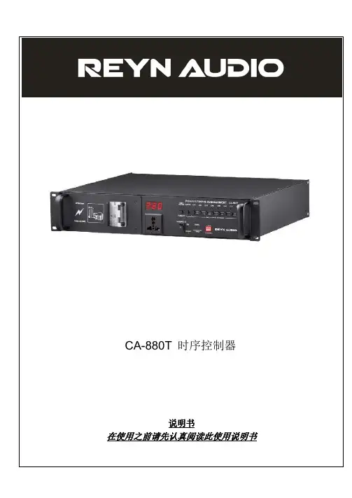
CA-880T 时序控制器说明书在使用之前请先认真阅读此使用说明书内容1. 特色 (2)2. 注意事项 (2)3. 综述 (4)3.1 前视图 (4)3.2 后视图 (4)4. 面板功能介绍 (4)4.1 空气断路器 (5)4.2 数码管显示屏 (5)4.3 超压警告及其指示灯 (5)4.4电源直通开关 (5)4.5 “一按通”开关 (5)4.6 万能电源插座 (5)4.7 时序电源开关及其指示灯 (5)4.8 待机指示灯 (6)4.9 地线未接通/错相接入警告灯 (6)4.10信号指示灯…………………………………………………………..….…6.4.11 拨码开关 (6)4.12欧美通用电源插座............................................................. .. (6)4.13Signal in/out 插座 (6)4.14 RS232 接口 (6)4.15总电源输入接口 (6)5. 软件更新 (7)1.8个通道电源输出;最多可设置16台控制器进行联机;硬件的按键通道开关和电源直通开关,即使软件出错也可以控制通道输出; 时序开关打开/关闭时自动搜索在线控制器,并进行时序控制;可通过信号接口对机器进行软件更新;具备地线未接通或者错相接入警告、超压警告、待机、运行、全部旁通、单独通道旁通全功能;数值实时电压显示;2.请认真地读用户手册,因为它可能包含一些关于操作细节、维护和技术数据等的一些重要信息,请保留好这个用户手册以备后用。
警告!♦不要让任何易燃物品,水,或者金属物品进入到这机器里面♦如果有任何液体溢到这个机器上面,请离开端口开关电源。
♦如果发生严重的操作失误,请立刻停止使用此机器,用立刻和你当地的经销商或者直接和我们联系。
♦请不要私自拆开机器-里面没有用户可用的配件。
♦不要擅自拆修机器,非专业人士拆修机器可能会让机器损坏或者发生误操作。
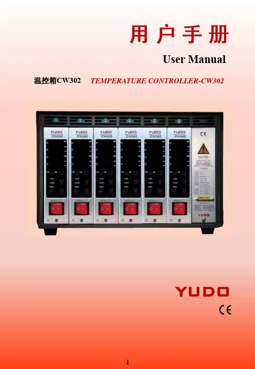
User Manual 温控箱CW302 TEMPERATURE CONTROLLER-CW302YUDOTemperature Controller USER’S MANUALCW302感谢使用YUDO温控卡! Thank you for choosing YUDO.使用产品前,敬请仔细阅读此手册,Please read this manual carefully before using the product.如有任何不明处请与本公司联系。
Please contact YUDO about questions.目录 CONTESTS1、使用和操作温控箱前注意事项 (4)Items to check before using the Controller& Operation Procedure (20)2、温控箱的基本结构 (5)Basic Structure of Controller (21)3、温控箱概述 (5)Outline of Controller (21)4、温控箱的表芯规格 (6)Controller Unit Specification (22)5、各部位名称 (7)Name of Component (23)6、操作模式 (7)Operation Modes (23)1)自动模式AUTO MODE2)待机模式STANDBY MODE3)手动模式MANUAL MODE7、菜单设定 (8)Menu Setting (24)1)用户一级菜单设定User's first level menu settings2)用户二级菜单设定User's second level menu settings8、错误功能显示 (13)Error Code Display Function (29)9、接线盒与线缆 (13)Connector and cable (29)10、接线端接线方法及示意图 (15)Diagram for Terminal Connection and Structure (31)11、电源接线图 (16)Electric Wiring Diagram (32)12、接线修改方法 (17)Wiring modification method (33)13、默认值 (18)Default Value (34)1)出厂默认值Factory Defaults2)用户可设定值User Settings Value14、安全标示 (19)Security Marks (35)15、故障现象及检查方法 (19)Check Point for Trouble Shooting (35)1、使用和操作温控箱前注意事项!注意内有高电压,在检查前请确认已关掉电源✓注意模具上的接线盒的接线情况和感温线类型✓检查模具接线规格与温控箱接线规格是否相匹配✓检查温控箱线缆是否匹配该温控箱✓检查接线盒和线缆✓检查发热线的电阻和绝缘状况,感温线是否连接线好✓模具安装在注塑机上并接上线缆✓检查电源开关和表芯开关是否关闭✓如输入电压(220V/380V)符合温控箱的电压规格,接上电线(输入电压值注明在温控箱箱壳的标签上,如输入电压与标签上注明的电压值不相符,那么敬请垂询当地的YUDO公司,然后改正温控箱的接线方式,接错线会引起温控箱的不正常运行,而且会毁坏表芯)✓确认温控箱的地零线(如不能区分零线(绿色),那么就易烧保险丝和可控硅)✓打开温控箱电源主开关,然后打开表芯的电源开关✓设定所需要的温度✓检查设定所需要温度达到没有,温度是否稳定注意:为了防止温度控制指令出故障,用于降温的风扇须一直运转。
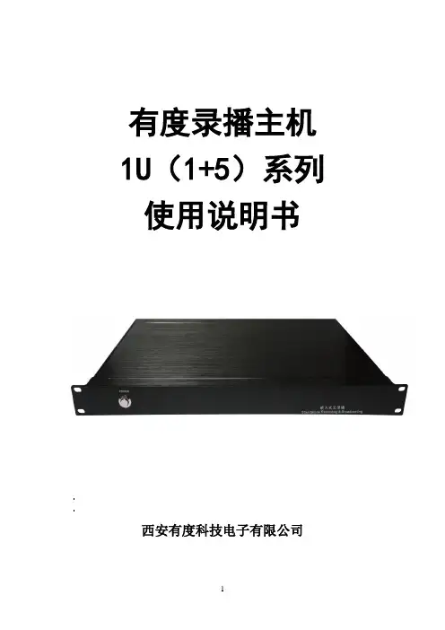
有度录播主机1U(1+5)系列使用说明书西安有度科技电子有限公司目录第一章:产品规格 (2)第二章:产品应用方案 (4)第三章:产品外特性 (5)第四章:录播主机的调试 (7)第五章:主机功能及操作说明 (8)5.1主界面 (9)5.2监视界面 (9)5.3输入通道 (11)5.3.1 通道界面说明 (11)5.3.2 通道设置 (12)5.4云台控制 (17)5.5导播功能 (19)5.5.1 导播切换/特效/画面分割 (20)5.5.2 字幕/音量控制 (21)5.5.3 角标/OSD信息/时间设置/附加OSD (22)5.5.4 主机工作状态 (24)5.5.5 片头片尾 (25)5.5.6 手动导播/自动导播 (25)5.5.7 电影模式/多图模式 (26)5.6系统功能 (26)5.6.1 一键开启 (27)5.6.2 录播设置 (27)第六章:使用时常见问题和解决方法 (42)第一章:产品规格1U录播主机是专为高清课堂录播开发的一款全自动录播设备。
它采用高速处理器和嵌入式Linux平台开发,结合IT领域中最先进的H.264视频压缩/解压缩技术、网络技术。
以硬盘作为存储介质,录播主机可记录教师现场授课的全过程、全部场景,同时生成教学实况录像,并以流媒体的方式在网络中直播给广大师生及管理者实时观看,并且可以保存在流媒体服务器中,提供点播服务。
1U(1+5)的产品规格见表1:项目设备参数性能指标系统操作语言中文/英文操作界面图形化菜单操作界面系统结构嵌入式Linux系统视频视频输入5路SDI输入+1路DVI-I输入视频输出1路VGA、1路DVI-I输出、1路3G-SDI环出视频显示单画面、画中画、多画面分割显示视频标准PAL制式/NTSC制式输入最大帧率1080P@60帧输入分辨率HDMI/VGA:1024*768@60HZ~1920*1080@60HZ3G/HD/SD-SDI:720x576-PAL, 720x480-NTSC,720P@50/60, 1080P@25~ 1080P@60音频音频输入2路音频输入音频输出2路立体声音频输出音频编码AAC录音方式声音与视频同步录制图像处理及存储视频输出格式MP4视频编码帧率1~30fps视频码率48kbps~20Mbps可调音频码率64Kbps数据存储内置一个SATA硬盘,最大支持3TB IOIO输入4个IO输入(最大5V,最小0V)IO输出2个IO输出(最大5V,最小0V)通信接口RS485接口支持1个RS485接口RS232接口支持2个RS232接口RJ45网络接口两个802.3ab 1000Base-T千兆网络接口USB接口支持2个USB接口功能导播功能视频预览/直播画面监视/预直播画面监视/视频切换/音频调整/一键开启/片头片尾/PTZ操作/特技效果/字幕、OSD信息、角标logo等录播功能实时推流/实时直播/同步录制/在线点播/远程互动/单流多画面/多流多画面软件升级支持网络升级、RS232串口升级存储模式支持内置硬盘、外接USB存储,支持USB录像导出,支持SAMBA共享下载直播协议标准的RTMP协议环境工作电压交流220V工作温度(℃)-10℃-85℃,指的是通风良好条件下的环境温度。
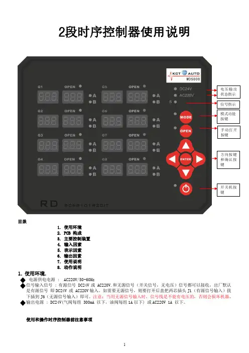
2段时序控制器使用说明目录1. 使用环境2. PCB 构成3. 主要控制装置4. 输入因素5. 表示因素6. 输出因素7. 使用说明8. 动作说明1. 使用环境.电源供电电源 : AC220V/50-60Hz:有源信号 DC24V 或 AC220V.和无源信号(开关信号,无电压)信号都可以接收,出厂默认即DC24V 或 AC220V 输入。
如需要无源信号,则要打开后盖把两芯插头J1(有源信号输入)拔下插到J6(无源信号输入)即可。
注意:当用无源信号输入时,信号线是不能有电压的,否则会损坏机器。
: DC24V(气阀每组 300mA 以下,油阀每组1A以下) 或AC220V 1A 以下。
使用和操作时序控制器前注意事项1)注意使用的电磁阀组的接线规格与控制器规格是否相符。
2)检查电磁阀电压规格与控制器的电压输出设定值是否相符。
3)检查电磁阀的连接电缆是否匹配该控制器。
4)检查模具信号线是否正确连接。
5)检查电源开关和控制卡的开关是否关闭。
6)确认控制器的输入电压是(AC220V),必须正确接线。
7)确认保护地线可靠连接。
8)使用前请确定已打开控制器电源主开关。
9 )使用前请确定已打开每个控制卡的电源开关。
10)使用前注意设定每个控制时段的时间与工作模式。
11)等待模具信号2. PCB 构成.1) 电源板, 输入输出部份.2) 按键与显示板3. 主要控制装置.1) 把AC220V 电源转换为内部驱动电源DC24V/3A, DC5V/1A.2) 按键与显示控制.3) 驱动继电器DC24V 或 AC220V 输出4. 参数设定方法.方向键。
a. 用于选择要设定设定的GATE .b.设定值的设定或移位时使用. 键a. 选择将要设定的GATE时使用.b. 设定完毕或从选择的GATE退出时使用键a. 设定各 GATE的作动模式(A mode >> B mode >> GATE off) 时使用.b. 设定各GATE的使用单位(999/99.9 /9.99)时使用. 键.a. 各 GATE 或全部的 GATE 手动 OPEN 时使用.键.a. 电源开关 ON/OFF功能.5.段数码管和指示灯显示.1) 在7段数码管上表示各GA TE的DEL(延时)时间和OPEN(打开)时间。

产品规格CH37582CeasYgen-3100XT/3200XTGenset Control 用于多机运行的∙ 标准并行应用,最多可支持 32 台发电机∙ 削峰运行 ∙ 待机运行 ∙ AMF (自动电源故障)运行 ∙ 紧急运行 ∙ 输入/输出运行 ∙ 孤网和实用程序并行运行∙ 易于设置和调试 ∙ 主站或从站控制功能 ∙ 完整的发动机、发电机和实用程序保护 ∙ 开/关转换 ∙ 五个通信端口: 以太网、2 个 CAN (CANOpen 和 J1939)、RS-485、USB∙ 可定制逻辑、HMI 屏幕和警报∙ 专用低温显示器变型 ∙ UL 61010、UL 6200、RoHS 2 和船舶(ABS 、LR )合规性说明Woodward 凭借 easYgen-3000XT 系列控制器提高了发电机组并行控制和电源管理系统的标准。
这些控制器随附了一些易于配置的标准化软件,便于针对各个应用进行量身定制。
通过提高连接性,可以快速、安全地连接到其它控件和通信系统;通过增强硬件,可以轻松更换上一代 easYgen-3000 系列控制器。
easYgen-3000XT 系列控制器可以运行各种规格和用途的发电机组。
该控制器针对启动、关闭、控制和保护适用的发电机组、断路器和实用程序专门设计了一套算法和逻辑。
可以在用于分布式发电用途的单个经济实用的发电机组控制器上进行标准化。
这些用途不仅包括单一独立应急备用电源,还包括在带有多个实用程序馈电和连接中断器的复杂分段式分布系统中对多个发电机组进行并行负载共享。
Woodward 的 easYgen-3000XT 系列并行发电机组控制器可以为 OEM 开关设备制造商、发电机包装公司和系统集成商带来卓越的多功能性和价值。
easYgen-3200XT 不仅适用于单一发电机组的孤网运行,还可以在包含单个实用程序的孤网和/或并行运行中最多对 32 台发电机组进行负载共享。
该系列控制器将完整的引擎-发电机控制和保护、先进的对等并行功能和创新功能整合到一个坚固、美观、用户友好的一体化产品包中。
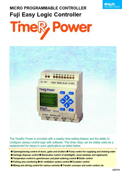
MICRO PROGRAMMABLE CONTROLLERFuji Easy Logic ControllerThe TimeRy Power is provided with a weekly time-setting feature and the ability to configure various control logic with software. This timer relay can be widely used as a replacement for relays in such applications as listed below.LEH110The TimeRy Power is helpful to increase all types of SAVINGS!About 50%Drastically minaturized control panels!Reduced hardware cost!Less wiring manpower!Energy-saving operationwith consideration to theenvironment!Promotion ofhighly efficientproduction!TimeRy Power has an extremely compact size of 72 x 90 x 55 mm. Thiscompact size contributes to the drastic reduction of control panel dimensions.For example, if a control circuitincluding 3 timers and 4 powerrelays is replaced with TimeRyPower, the mounting space maybe reduced by about 50%! (Ascompared with our existingmodels.)TimeRy Power is priced to sell at a user-oriented lowerprice.This will greatly lighten the burden of hardware costs.For example,if a control circuit including 3 timers and 4 power relaysis replaced with TimeRy Power, the cost will be reducedby about 20%! (As compared with our existing models.)In the conventional method, the troublesome wiring of timersand counters and connection of discrete components isinevitable. TimeRy Power allows a wired logic function to beachieved with programmed software through operation ofoperation switches. Thus the more complicated the logicbecomes, the more the wiring manpower will be reduced! Inaddition, minor modifications can be quickly implemented withthe operation switches on the spot, and thus TimeRy Powerwill powerfully help the user promote standardized hardwarespecifications!TimeRy Power allows the userto promote environmentallyfriendly measures through plantoperation with reducedconsumption of electricity andfuel! This energy-savingoperation is realised by suchfunctions as automatic schedulemanagement with daily andweekly timers, and temperaturecontrol with analog inputs.TimeRy Power comesstandard with logic schemesfor control applications ofroutine plants and systems.TimeRy Power can easilycopy logic schemes by useof the optional memory pack.The control logic connectionstake considerably less timeto implement than traditionalhard-wiring. SPACE SAVINGCOST SAVINGWIRE SAVINGENERGY SAVING TIME SAVINGMonitoring screen displays all operating conditions The monitoring screen on the front of TimeRy Power indicates to the user the total status of TimeRy Power at a glance. This screen displays the status of l/Os, internal relays, timers, counters, the analog current values and the clock time, as well as a monitoring screen of the control logic operation.Control logic is easily configured in ladder diagram format with software Control logic wiring in TimeRy Power is implemented with software in a ladder diagram format that is developed from a traditional relay schematic diagram. The user has only to wire the TimeRy Power with software as is shown in an existing schematic diagram.Large power output relays with switching capacity of lOA are provided TimeRy Power includes large power output relays with a per point switching capacity of 10A at 250V AC, or 8A at 30V DC. These output relays can be directly connected to illumination lamps, valves and small motors for control. Schedule management is achieved by using clock function A model with a clock function is provided so that the user may simply and economically realize daily or weekly schedule management using just a single TimeRy Power without any expensive time switch required In addition, overseas use such as in Europe is also ensured since the clock function is equipped with a summer-time selection function.2 channel analog inputs are standard (DC 24 V, with RTC) TimeRy Power comes equipped with 2 channel analog inputs as a standard. Simple control of analog quantities, such as temperature, speed, and voltage can be achieved without any optional analog device.Password feature is provided for security TimeRy Power contains a password feature for preventing unexpected modification of software with switch operation.Special mounting hardware is not required TimeRy Power can be mounted with screws on sliding type fixing holes as well as DIN rails without using any special mounting clamps.Maintenance-free EEPROM is usedSince software information is stored into an EEPROM that does not require battery backup, TimeRy Power can be handled without any consideration for the maintenance that would be necessary in the case of hardware logic. Complies with CE marking and UL/cUL standards The TimeRy Power is widely applicable throughout the world, and the standard model complies with various global standards such as CE marking and UL. Software data saving with loader and simulation via personal computer are availableSoftware data can be saved by using an optional loader program. The data will help the user to standardize wiring diagrams. Wiring of loader software is implemented in asimilar manner as forTimeRy Power.Moreover' theconfigured logic canbe simulated in apersonal computer,and thereforeperformance of thelogic scheme inTimeRy Power canbe verified prior toinstallation.Power supply terminals Power supply terminals for 100 to 200 AC and 24V DC are provided.Monitoring screenScreen displays logic diagram and monitoring operating conditions. Digital output terminals Power relays with large capacity of 10A are provided onboardOperation switchesOperation switches are used forwiring logic and setting timers andcounters.Interface portAn interface port is provided forconnection to a loader or to attacha memory pack.Analog input terminalsModel with 24V DC RTC comesstandard with analog inputs. Digital input terminalsThe TimeRy Power is helpful to increase all types of SA VINGS!s Specificationsq General specificationsNQ2P10R-14 [1NO2P10R-52Power supply voltage 20.4 to 28.8V DC 85 to 264V AC Power consumption 0.3W 0.8WOutput currentMax.10AElectrostatic discharge IEC801-2 Severity3Contact discharge ±4kV, aerial discharge ±8kVRadioelectromagnetic field IEC801 -3 10V/mOperating ambient IEC801-4 Severity3 2kV temperature0 to 55¡CRelative humidity 20 to 90%RH no condensation Vibration IEC68-2-6 9.8m/s 2ShockIEC68-2-27 147m/s 2Construction IP20Dimensions72 x 90 x 52mm (DIN rail)q I/O specificationsNQ2P10R-14NQ2P10R-52No. of input points 6pointsRated voltage 0 to 28.8V DC 0 to 265V AC Rated current 3mA0.5mA/110V 1mA/220V Operating voltage ON:15 to 28.8V ON:79 to 265V OFF:0 to 5VOFF:0 to 40VDelay time OFF ON:3ms OFF ON:50ms ON OFF:5ms ON OFF:50ms Analog voltage*0 to 10V DC ÐResolution:8bits No. of output points 4pointsLoad current10A/250V AC or 8A/30V DC*Analog input:only for NQ2P1 OR-14CInputOutput q SpecificationsNQ2P10R-Q2P10R- CProgramming language Ladder, function brockProgram memory capacity 240steps (4elements x 60lines)Backup Built-in EEPROM, memory pack option Input relay 12points (11 to C)Output relay 8points (Q1 to Q8)Auxiliary relay 15points (M1 to MF)RTC relay 8points (C1 to C8)Counter 15points (T1 to TF)Timer 4points (P1 to P4)Analog comparison 4points (G1 to G4)Analog input X 2channel (A1 to A2) only for DC RTC X Os Dimensions (mm)Safety Considerationsq For safe operation, before using the product read the instruction manual or user manual that comes with theproduct carefully or consult the Fuji sales representative from which you purchased the product.q Some of the products listed in this catalog may have limits on their use or location or may require periodic inspections. Call Fuji's sales representative for further information.q For safe operation, wiring should be conducted only by qualified engineers who have sufficient technical knowledge about electrical work or wiring.¥Appearance and specifications are subject to change without prior notice for the purpose of product improvement.Fuji Electric Co., Ltd.ED & C ¥ Drive Systems CompanyGate City Ohsaki, East T ower11-2, Osaki 1-chome, Shinagawa-ku, T okyo, 141-0032, Japan Phone: +81-3-5435-7135~8Fax: +81-3-5435-7456~9Materials covered in this document are subject to revision due to the modification of the product.Printed in Japan 2000-3 (COO/COO) M50 FISs ProductsItemOrdering code Specification(Product code)TimeRy PowerNQ2P1 OR-1424V DC power supply, input 6points, output 4points Ry10A, no clock functionNQ2P1 OR-14C 24V DC power supply, input 6points, output 4points Ry10A, clock function, analog 2channel NQ2P1 OR-52100 to 200V AC power supply, input 6points, output 4points Ry10A, no clock function NQ2P1 OR-52C 100 to 200V AC power supply, input 6points, output 4points Ry10A, clock function Loader software NQ4H-SE Personal computer loader software (with connection cable)Memory packNQ8P-MPFor program saving and transferring。

BALA OP EN SYSTEMInstruction ManualV E R . N O . 0 3 0 7 – M N B O E N OGreetingsThank you for using YUDO Hot Runner System.YUDO fabricated Hot Runner System with its best efforts so that customers can use it most easily. However, there are many parts for customers to pay attention because it is a technical product.Please read this manual well and use it.YUDO reserves the right to change the provisions of these descriptions and specifications at any time without notification to customers.Please discuss with YUDO in advance when technical support is needed.Contents1. Basic Structure of YUDO Hot Runner System1) Basic Structure of Nozzle2. Outline of Hot Runner System3. Kinds of Hot Runner System1) Open Gate, Shut Off Gate, Valve Gate4. Meaning of YUDO Open Nozzle Standard1) BALA Open (CC, CA, CE, CF Type) Specification2) BALA Open (TAC, TOE, TLC Type) SpecificationBALA 18 SeriesBALA 25 SeriesBALA 35 SeriesBALA 45 Series3) Shape and symbol of gate4) Nozzle part machining5) Gate part machining6) Machining of Locating Ring Part7) Machining of Lead Wire Slot Part8) MODU Plate Machining (Clamping Plate, Spacer Block, Hold Plate)9) Machining of Connecting System Part5. Check Items of Hot Runner System1) Check of Hot Runner System Part 2) Electric Check of Hot Runner System3) Dimensional Check of Hot Runner System6. Assembly of Hot Runner System (MODU System)7. Operation of Hot Runner System1) Installation 2) Caution before operation3) Maintenance8. Disassembly and Assembly1) Disassembly and assembly when replacing nozzle heater and T/C9. How to Recognize Product Standard and System10. Trouble and CountermeasureA -Not being heatedB -Occurrence of carbonizationC -Resin leakageD -In case that resin leaks on manifold but heater is not disconnected.E -In case that resin leaks on manifold, heater is not disconnected, and coolant leaks todestroy insulation of heater.F -In case that manifold heater is disconnected.1. Basic Structure of YUDO Hot Runner SystemPLAN VIEWSIDE VIEWHot Runner and Mold Parts ListNo No.. Description DescriptionNo No.. Description Description1 Locating Ring19 Socket Head Cap Bolt 2 Socket Head Cap Bolt 20 Lower Insulation Pad 3 Clamping Plate 21 Dowel Pin 4 Spacer Plate 22 Dowel Pad 5 Holding Plate 23 Lock Pin 6 Cavity Plate24 Sheath Heater 7 MODU Assy Bolt(B2) 25 Seal Ring 8 Mold Assy Bolt(B1) 26 Nozzle Body 9 Socket Head Cap Bolt 27 Tube Heater 10 Center Pin Cover 28 Snap Ring 11 Center Pin 29 Nozzle Tip12 Nozzle Locator 30 Nozzle Thermocouple 13 Socket Head Cap Bolt 31 Gate Bush14 Pin Guide Bush Support Pad 32Power +T/C Connector 15 Upper Insulation Pad 16 Upper Insulation Pad 17 Manifold Thermocouple 18Manifold Block1) Basic Structure of NozzleNozzle serves a route to feed the resin injected by injector to cavity, and is a device to maintain resin at constant temperature until it is injected.Nozzle may be used by selecting proper specification according to injection amount, and selecting proper type of nozzle according to shape or characteristics of gate part.Nozzle Parts ListNoNo DescriptionDescription BALA 18BALA 18 25BALA 25 35BALA 35 Q’ty ty RemarkRemark 1Cu Ring Ø 22*2.3t 12Nozzle Ø 38*L Ø 50*L Ø 60*L 13Nozzle T/C TPIC□□ or TPCA□□ 14Nozzle HeaterHT18□□ orHC18□□HT25□□orHC25□□HT35□□ orHC 35 □□15 C Tip Insert TC Ø 10.5*47 Ø 13*55 Ø 17*66 16 C Tip Bush Ø 12.5*34.6 Ø 16*41.5 Ø 22*51.4 17Snap Ring ACRICS000180ACRICS000250ACRICS000350 18CA Gate Bush Ø 25*15 Ø 35*20 Ø 45*25 19CF Gate Bush Ø 28*18 Ø 38*25 Ø 48*30 11010 LCA Gate Bush Ø 12.5*44 Ø 16*51.5 Ø 22*62 11111 LCF Gate Bush Ø 25*26, 31 Ø 35*40, 50 Ø 45*55, 65 11212 CE Gate Bush Ø 25*15 Ø 35*20 Ø 45*25 1CC Type2. Outline of Hot Runner SystemHot runner system is a method devised to produce product continuously without sprue or runner through the heated runner which serves a route of melted resin in order to fill cavity in plastic injection mold and by maintaining it as melted state.Advantage and Disadvantage of Hot Runner System◈Advantage1) Because product must be produced using 100% of new resin without any loss at all time,defect or trouble due to foreign material can be prevented.2) Filling up cavity is needed only, because resin is always being melted up to gate, thus thetime of injection, measurement, cooling and frame opening/closing is shortened as well asthe time to take out sprue and runner.3) Improvement of product qualityBecause the injection pressure of injection molder is directly transferred to cavity, theproblem of product shrinkage, weld, and deformation due to internal stress can be solved.4) Increase of mechanical efficiencyEfficiency of molder is enhanced because injection amount, pressure, mold openingdistance may be decreased as much as the amount of sprue and runner.5) Extension of mold lifeThe pressure exerted on the mold is decreased due to decrease of injection pressure and 3-stage mold of large type may be converted into 2-stage mold in case of using hot runnersystem, so that the trouble which can occur in 3-stage mold may be prevented.◈Disadvantage1) Increase of mold cost : Hot runner components and controller are necessary.2) Technical manpower is necessary for maintenance and repair.3) Sufficient review is necessary for mold design depending on shape of resin and productused.3. Kinds of Hot Runner System1) OPEN GATEa. Direct Gate : This is the most basic system where flow route is equipped with heater.(There are BALA series in YUDO.)b. Pin Point Type Gate : Gate mark may be minimized, but a little more pressure is required.Type Basic Shape Product Shape of Gate Part Nozzle Type Direct Gate BALA TOE,TOL SystemPin Point TypeGateBALA CC, CA,CF System2) SHUT – OFF GATEa.Spring Type Valve Gate :This is the most simple valve gate system, but much injectionpressure is required, so that gate mark is unstable.(There are no related products in YUDO)b.Electrical Shut–off Gate :This may be mainly used for small products, but specialtemperature control device is required, and high technology is required for management of function.(LOVO Series Nozzles of YUDO)◈Valve GateHydraulic Valve GateHydraulic Valve GateAdvantage Disadvantagea. High pressure can be obtained by usingrelatively small cylinder.b. The life of “0” ring used is long relatively.a. Hydraulic unit is required.b. Because oil is used, there is much possibility of oilleakage and surrounding is not clean when oiling.c. Operation and management is difficult.d. There are many elements of troubles due tocarbonization of oil.e. Response speed is slow relatively.Pneumatic Valve GatePneumatic Valve GateAdvantage Disadvantagea. Structure is simple.b. Response speed is relatively fast.c. Operation and management are easy.d. Equipment investment cost is relatively small.e. Because air is used, damaging of “0” ringdoes not cause contamination of surrounding.a. Relatively large cylinder is required.b. The life of “0” ring is shorter than hydraulic type.4. Meaning of YUDO Valve Nozzle Standard1) BALA (Open CC, CA, CF Type) SpecificationBIS Series(Single Type) BIM Series(Manifold Type).2) BALA (Open TAC, TOE, TLC Type) SpecificationBIS Series (Single Type) BIM Series(Manifold Type)BIM Series(Manifold Type)a. BALA 18 Series a. BALA 18 Series♦ Nozzle length L: Minimum = 075mm Maximum = 175mm♦ T/C MODEL : TPIC06(J) or TPCA06(K) ♦ L length can be made according to order.b. BALA 25 Series b. BALA 25 Series♦ Nozzle length L: Minimum = 090mm Maximum = 320mm♦ T/C MODEL : TPIC06 or TPCA06♦ L length can be made according to order.BIS Series BIS SeriesNozzle Nozzle Model Model Model L HEATER HEATERMODEL MODELT/C T/CMODEL MODELBIM Series BIM SeriesNozzle Nozzle Model Model Model BIS-18-□□□-075 075 HT180351 TP□□051 BIM-18-□□□-075 BIS-18-□□□-085 085 HT180451 TP□□061 BIM-18-□□□-085 BIS-18-□□□-095 095 HT180551 TP□□071 BIM-18-□□□-095 BIS-18-□□□-105 105 HT180651 TP□□081 BIM-18-□□□-105 BIS-18-□□□-115 115 HT180751 TP□□091 BIM-18-□□□-115 BIS-18-□□□-125 110 HT180851 TP□□101 BIM-18-□□□-125 BIS-18-□□□-135 135 HT180951 TP□□111 BIM-18-□□□-135 BIS-18-□□□-145145HT181051 TP□□121BIM-18-□□□-145BIS Series BIS Series Nozzle Model Nozzle Model L HEATER HEATERMODEL MODEL T/C T/CMODEL MODEL BIM Series BIM SeriesNozzle Model Nozzle Model BIS-25-□□□-090 090 HT250433 TP□□06 BIM-25-□□□-090 BIS-25-□□□-100 100 HT250533 TP□□07 BIM-25-□□□-100 BIS-25-□□□-110 110 HT250633 TP□□08 BIM-25-□□□-110 BIS-25-□□□-120 120 HT250733 TP□□09 BIM-25-□□□-120 BIS-25-□□□-130 130 HT250833 TP□□10 BIM-25-□□□-130 BIS-25-□□□-140 140 HT250933 TP□□11 BIM-25-□□□-140 BIS-25-□□□-150 150 HT251033 TP□□12 BIM-25-□□□-150 BIS-25-□□□-160 160 HT251133 TP□□13 BIM-25-□□□-160 BIS-25-□□□-170 170 HT251233 TP□□14 BIM-25-□□□-170 BIS-25-□□□-180180HT251333TP□□15BIM-25-□□□-180c. BALA 35 Series c. BALA 35 Series♦ N ozzle length L: Minimum = 90mm Maximum = 370mm♦ Two heaters and T/C are used, if nozzle length L is 330mm or more. ♦ T/C MODEL : TPIC06 or TPCA06♦ L length can be made according to order.d. BALA 45 Series d. BALA 45 Series♦ N ozzle length L: Minimum = 110mm Maximum = 320mm♦ Two heaters and T/C are used, if nozzle length L is 310mm or more. ♦ T/C MODEL : TPIC06 or TPCA06 ♦ L length can be made according to order.BIS Series BIS SeriesNozzle Model Nozzle Model L HEATER HEATERMODEL MODELT/C T/CMODEL MODELBAM Series BAM SeriesNozzle Model Nozzle Model BIS-35-□□□-090 090 HT350483 TP□□046 BIM-35-□□□-090 BIS-35-□□□-100 100 HT350583 TP□□056 BIM-35-□□□-100 BIS-35-□□□-110 110 HT350683 TP□□066 BIM-35-□□□-110 BIS-35-□□□-120 120 HT350783 TP□□076 BIM-35-□□□-120 BIS-35-□□□-130 130 HT350883 TP□□086 BIM-35-□□□-130 BIS-35-□□□-140 140 HT350983 TP□□096 BIM-35-□□□-140 BIS-35-□□□-150 150 HT351083 TP□□106 BIM-35-□□□-150 BIS-35-□□□-160 160 HT351183 TP□□116 BIM-35-□□□-160 BIS-35-□□□-170 170 HT351283 TP□□126 BIM-35-□□□-170 BIS-35-□□□-180180HT351383 TP□□136BIM-35-□□□-180BAS Series BAS SeriesNozzle Model Nozzle Model L HEATER HEATERMODEL MODEL T/C T/CMODEL MODEL BAM Series BAM SeriesNozzle Model Nozzle Model BIS-45-□□□-110 110 HT3504 TP□□04 BIM-45-□□□-110 BIS-45-□□□-120 120 HT3505 TP□□05 BIM-45-□□□-120 BIS-45-□□□-130 130 HT3506 TP□□06 BIM-45-□□□-130 BIS-45-□□□-140 140 HT3507 TP□□07 BIM-45-□□□-140 BIS-45-□□□-150 150 HT3508 TP□□08 BIM-45-□□□-150 BIS-45-□□□-160 160 HT3509 TP□□09 BIM-45-□□□-160 BIS-45-□□□-170 170 HT3510 TP□□10 BIM-45-□□□-170 BIS-45-□□□-180 180 HT3511 TP□□11 BIM-45-□□□-180 BIS-45-□□□-190 190 HT3512 TP□□12 BIM-45-□□□-190 BIS-45-□□□-200200HT3513TP□□13BIM-45-□□□-2003) Shape and symbol of gateModel and SymbolModel and Symbol Gate Shape Gate Shape ApplicationApplication BIM □□□ CC BIS □□□ CC- To obtain pin-point gate using open nozzle system.- Gate area to be machined by customer.BIM □□□ CA BIS □□□ CABIM □□□ CE BIS □□□ CE- Precisely machined Gate Bush will be applied. - Lengh of LCA is the height of cavity plate.- In addition to the gate mark, the gate bush mark will be added to the part. - Easy replaceable Gate bush.BIM □□□ CF BIS □□□ CF- Gate bush designed to enable hot or cold fluid to flow directly around the gate. - Fast cycle molding applications.- Molding condition improved in engineering - Easy replaceable Gate BushBIM □□□ LCA BIS □□□ LCA- Precisely machined Gate Bush will be applied - Length of LCA is the height of cavity plate- In addition to the gate mark, the gate bush mark will be added to the part- Easy replaceable Gate BushBIM □□□ LCF BIS □□□ LCF- Gate bush designed to enable hot or cold fluid to flow directly around the gate. - Fast cycle molding applications.- Molding condition improved in engineering - Easy replaceable Gate BushBIM □□□ TAC BIS □□□ TAC- Simple construction for Direct Injection- In addition to the gate mark, the gate bush mark will be added to the part- Easy replaceable Gate BushBIM □□□ TLC BIS □□□ TLC- Simple application- Wide application, poor gate vestige and post molding op eration required- Restricted application to heat -sensitive material- Simple construction for Direct Injection with minimum sprue.BIM □□□ TOE BIS □□□ TOE- In addition to the gate mark, the gate bush mark will be added to the part- Easy replaceable Gate Bush- Simple construction for Direct Injection4) Nozzle part machining1) The part with * mark should be precisely machined.2) YUDO requires holding plate by all means in using hot runner. Of course, there is noproblem in using YUDO system by directly attaching nozzle to cavity plate. However, when hot runner is disassembling and assembling is repeated on the way of test injection andcorrection of mold, this may cause of resin leakage, heater wire breakage, etc.but also Such increase of manhour causes more cost than addition of holding plate in terms of total cost in the end, and causes drop in reliability of mold.Structure of general hot runner Structure with holding plate required by YUDOStructure with holding plate required by YUDO3) Machine the space where nozzle flange partwill be inserted in holding plate.4) Machine lead wire slot.Machine heater so that lead wire may come outof the lower surface of holding plate. Onlysuch arrangement makes it possible to changeheater directly on injection machine withoutdisambling and assembling of hot runner incase of wire disconnection.5) Use M8-P1.25 tap for manifold clamping bolt.Bolt position is 68mm in manifold widthdirection and 60mm in length direction asshown in the drawing below.MODELMODEL LØDØD ØD1ØD1 ØD2ØD2 BIM 18 □□ □□□ □□□ 32 38 40 BIM 25 □□ □□□ □□□ 40 50 55 BIM 35 □□ □□□ □□□ 50 60 655) Gate part machininga. CC a. CC Type Gate Type Gate Type GateMODEL MODELØD ØDØD1ØD1 ØD2ØD2 ØGATE ØGATE L L1L1L2L2 R BIM 18 CC □□□ 32 18 14 0.6~1.6 9 12 14.5 7 BIM 25 CC □□□ 40 25 20 1.0~2.0 12.32 15 18 10 BIM 35 CC □□□5035 28 2.0~4.0 16.5202314b. CA Type Gate b. CA Type GateMODEL MODELØH ØHØD ØD ØD1ØD1 L1L1 L2L2 BIM 18 CA □□□ 32 8 20 2 10 BIM 25 CA □□□ 40 12 28 2.5 12 BIM 35 CA □□□ 50 14 38 3 17 BIM 45 CA □□□6020483.520C. C. CF Type Gate CF Type Gate CF Type GateMODEL MODELØDH ØDH ØD1ØD1 ØD2ØD2ØD ØD ØD3ØD3 L1L1 L2L2 L3L3L4L4BIM 18 CF □□□ 32 20 28 8 3 2 10 18 11.5 BIM 25 CF □□□ 40 28 38 12 6 2.5 12 25 15.5 BIM 35 CF □□□ 50 38 48 14 6 3 17 30 20~1 BIM 35 CF □□□6048582063.5203524.5The most important dimension is ØD1. It is designed sothat inflow of resin into heater part may be prevented by side contact of ØD1 and nozzle end part.L1 dimension is important, but there is thermal expansion, so that L1 section is not major point of resin leakage.There should be coolant hole within a maximum of 30mm from gate center.There should be coolant hole within a maximum of 30mm from Gate center.There should be coolant hole within a maximum of 35mm from gate center.e. LCA Type Gate d. CE Type Gate e. LCA Type GateCE CE MODEL MODELE ØD ØD ØD1ØD1 L1L1 L2L2 LCA LCA MODEL MODELH ØD ØD ØD1ØD1 L1L1 L2L2 BIM 18 328 20 2 10 BIM 18 408 20 2 10 BIM 25 40 12 28 2.5 12 BIM 25 50 12 28 2.5 12 BIM 35 50 14 38 3 17 BIM 35 60 14 38 3 14 BIM 45 60 20483.520BIM 457020483.520g. TOE, TOL Type Gatef. LCF Type Gateg. TOE, TOL Type GateM ODEL ODEL L5L5 L6L6 L7L7 L8L8 L9L9 ØH ØH ØH1ØH1 P F R N E BIM 18 2 10 18 11.5 6 32 40 21.5 38 7 2.5 15 BIM 25 2.5 12 25 15.5 6 40 50 26.5 50 10 3 30 BIM 35 3 17 30 20 8 50 60 31.5 60 14 3 40 BIM 45 3.5203524.58 60 70 36.5 70 19 3 45e. CC Type Gate Machining Me e. CC Type Gate Machining Method thod thod① Cut and rough the part while nozzle will be assembled on cavity plate with machining center.ⓐ part should be cut as circular machining at first so that reference may be caught during discharging machining of gate part.ⓑ part should be machined with drill or end mill as roughing concept.② Cut the part where nozzle end part will be assembled.(ⓒ part in the drawing).Adjust depth while machining circle at machining center because this part has precise tolerance. Circle machining method is shown in the drawing.③ Machine ⓓ part by machining shape with end mill.④ Machine the gate in rough state using end millwith 0.5mm side allowance.⑤ Machine the gate part with electric discharge. Discharge electricity with sufficient time in order to make it smooth as far as possiblebecause gate part is a flow route of resin. Machine gate part with electric discharge by all means.The reason isthat precise machining is necessary to avoid gate deformation to product surface direction due to machining force in case that cavity is weak, but also when tool swings the concentricity between ⓒpart and gate will not coincide with each other, in case that machining is performed with end mill or drill. Shape of jig for electric discharge is shown in the drawing.It is possible to maintain surface hardness of gate and to lengthenthe life of gate through heat-treatment of gate surface by electric discharge machining.6) Machining of Locating Ring PartUse of MNL 23, 33Use of MNL 23, 33① Locating ring fixes mold and nozzle locator and functions as a guide with respect to center of injector holding plate. Locating ring seat should be fixed so as not to be moved by machining hole on clamping plate by all means. And, some part(a part) of locating ring should be designed so as to be pressed by injector fixing plate. Fixing of locating ring with only locating ring fixing bolt may be a cause of resin leakage by injection back pressure. Moving of locating ring maybe a cause of resin leakage between nozzle locator and manifold. ② Machine the locating ring seat on clamping plate.③ Machine the seat on clamping plate in order to assemble nozzle locator. ④ Locating ring should be machined by contractor in accordance with specification of injector.⑤ Refer to the drawing in the right side for machining method.7) Machining of Lead Wire Slot Part① Machine the lead wire slot by selecting a hole of proper size according to wire quantity. ② Wire surface should be prevented from being damaged drawing wiring by machining the slot in proper round(minimum R10) at the part where wire slot is bent.③ Lead wire slot should be machined differently according to quantity of wire. ④ Wire slot machining size pursuant to the quantity of wire is as follows.Nozzle Lead WireNozzle Lead Wire Slot Machining Detail Slot Machining Detail Slot Machining DetailW = 26 W=46DP Zone DP Zone 10 1~2 10 1~4 15 3~4 15 5~8 20 5~6 20 9~12 25 7~8 25 13~15 309~103016~188) MODU Plate Machining(Clamping Plate, Spacer Block, Hold Plate)① Machine the guide pin hole for fixing MODU plate position. It is more advantageous to machine those 3 MODU plates and cavity platesimultaneously when machining guide pin hole. Simultaneous machining can reduce error due to machining during MODU plate assembly.② Machine the dimension by referring to the drawing.③ Machine the bolt hole for fixing MODU plate. Machine the hole in clamping plate and spacer block, and machine the tap in hold plate.④ Bolt(B2) standard differs according to mold base standard. If the size of mold base is 600mm or less, install 4 or more M16 units of bolts ; and if the size of mold base is 600mm or more, installmore than 6 units of M16 bolts or 4 units of M20 bolts.⑤ Machine the bolt hole for fixing MODU plate and cavity plate. Machine the hole on MODUplate and machine the tap on cavity plate. Follow the dimension for machining position and bolt specification, and the enterprise should provide exact location and specification when ordering MODU.⑥ The length of ØD H7g6 part of guide pin should be H+5mm or more longer from the holdplate face(cavity plate position must be fixed in advance of fixing the end part of nozzle when assembling MODU), and the length of ØD-3 part should be fabricated 10~15mm longer than the longest nozzle(cavity plate position is guided first,rather than nozzle tip end part when assembling mold). Otherwise, the end part of nozzle tip contacts with mold and is damaged when assembling MODU plate on mold.⑦ Guide pin specification is as followsStandard used Standard usedDD1D1D2D2D3D3HH1H1Mb MbCPN30L 30 35.5 46 60 10 8 M6 CPN40L 40 45.5 67 90 20 10 M12 CPN254L 25.4 30.5 46 60 10 8 M6 CPN3175L31.7535.546601010M6⑧ Guide pin is 10~15mm longer than nozzle to be assembled to cavity plate first, so thatnozzle is guided by cavity plate.⑨ Because precise fitting is made when assembling ⓐpart of nozzle, guide pin must beassembled to cavity plate first to play a role of guide.9) Machining of Connecting System PartConnector is a component used to make electric connection smooth with the mold, and is essentially used in the mold equipped with hot runner system.24P connector is used as standard connector in YUDO.It is generally more convenient to install connector at the upper surface of mold or on the opposite surface of worker.The drawing below shows an example of machining, and the machining size differs according to quantity of connector.In processing of maching of mold, the datum base plane will be the base plane of the hold plate5. Check Items of Hot Runner System1) Check of Hot Runner System PartCheck if the quantity of component is accurate by checking part list of the system. In theevent that the quantity of component is not accurate in system assembly, the assemblyschedule may be delayed due to lack of component.Especially, check if the quantity of “0” ring, pin and bolt coincide with the necessaryquantities.In case of MODU type, check if the component to be assembled on MODU plate whichshould be attached.(Connecting Box, Solenoid Valve, Wiring Name Plate)1) Check if heater and T/C are properly assembled to the nozzle. Give number to heater andT/C and bind lead wire together, so as to prevent from wrong wiring,between heater andT/C wire.2) Check if the component are attached exactly on manifold.(Upper, Lower Riser Pad, Nozzle Locator, Thermocouple, etc.)Give number to heater and T/C and bind lead wire together, so as to prevent from confused wiring.3) Please Check whether MODU system has assembled correctly.Check if the heater and the snap ring were assembled correctly and the nozzle tip is fostened properly.4) Check connecting box.Check if there is connector and solenoid valve and if the quantity is proper.Check if silencer and one touch nipple are attached to solenoid valve.2) Electric Check of Hot Runner SystemBecause hot runner is equipped with electric components differently from other moldcomponents, thorough check is necessary. Especially, the insulation state and divisionbetween heater wire and T/C wire are very important in heater part. It should be checked by all means.(1) Check of Nozzle Heater and T/C(1) Check of Nozzle Heater and T/C① Check insulation state by between the powerline of nozzle heater and body of nozzle by useof tester. At this time, resistance should beselected by turning selection switch of tester.② Check resistance of heater or existence of open wire between two power lines by use of tester. The checked resistance value may be basis of determining capacity of heater and capacity of controller. At this time, select resistance by turning knob switch of tester.Calculation method is as follows.(Diagram of Ω law)If the measured resistance value and the voltage are known, it may be calculated with E 2/R. Ex) If R=60Ω E=220 VW=E 2/R 2202/60=806.66 W③ Check if there is any open wire between two linesof thermocouple(T/C) by use of tester. There are ground and non-ground type in T/C. Generally, ground type is used. However, non-ground type T/C should be used in case of ultra-preciseinjection. T/C is grounded to nozzle-body in case of ground type, and it is insulated in case of non-ground type.④ Check if T/C type is IC or CA by checking coating color of T/C.The points how to identify the polarity of T/C is as follows.Division Wire(+) Wire(-)YUDO Sleeve ColorCoating color Red stripe Yellow stripe Material Iron Constantan IC (J)Magnetism Magnetic Non-magnetic YellowCoating colorRed stripe Blue stripe Material Chromel Alumel CA (K)MagnetismNon-magneticMagneticBlueI = current (A) E = voltage (V) R = resistance (Ω) W= power consumption (W)(2) Check of manifold Heater and T/C① Check insulation state between the power lines of manifold heater and manifold block. (Same as how to test insulation of nozzle) ② Check resistance of heater or existence of disconnection between two power lines of nozzle heater. (Same as how to test disconnection of nozzle)③ Check existence of disconnection between two lines of thermocouple(T/C) by use of tester. (Same as how to tester disconnection of nozzle)④ Check whether T/C type is IC or CA by checking coating color of T/C.⑤ Check resistance value between power lines of manifold heater by use of tester. The checked resistance value becomes a basis to determine heater capacity and controller capacity. (Same as how to check resistance value of nozzle) The maximum capacity of YUDO controller is 15A each , and feasible range in proper usage is up to 10~12A.3) Dimensional Check of Hot Runner SystemDimension inspection of hot runner system has close relationship with mold, and dimension measurement is used as important data when assembling mold, so that it should be exactly measured.(1)(1) Dimension check of manifold Dimension check of manifold① Check manifold thickness and riser pad thickness.Manifold thickness is usually 45T(tolerance: +0.05~0), and may be 50T(tolerance: +0.05~0) in some cases. Riser pad thickness is usually 10T(tolerance: 0~-0.02) in upper side ofmanifold and 15T(tolerance: +0.05~0) in lower side. Tolerance scope of measured dimension including riser pad is 70T or 75T(tolerance: -0.04~+0.05).② Check the distance between dowel pin center and gate center for gate position.Manifold gate distance is a dimension to consider thermal expansion quantity, so that it differ from gate distance on mold drawing. Thermal expansion quantity is calculated by using the following formula.◈ FormulaΔL = (1.23*10-5)*L*ΔT ΔT = (To-Tm) ΔL = Thermal expansion quantity 1.23*10-5 = Thermal expansion coefficientTo = Manifold temperature Tm = Mold temperature L = Distance between manifold Center and gateEx) L = 127mm To = 280℃Tm = 60℃ΔT = (280-60) = 220℃ΔL = (1.23*10-5)*127*220 = 0.34366mmThe distance between manifold center and gate is 126.65mm. ③ Thermal expansion quantitypursuant to the length is same as the diagram.(2)(2) Check of nozzle dimension Check of nozzle dimension① Check if the same thermal expansion coefficientof manifold is applied for BALA nozzle. ② Check dimension of nozzle ØD and ØD1 part and 30mm part.③ Check dimension of nozzle L1. The dimension of L1 shall be machined short considering thermal expansion quantity. Because the normal dimension on the drawing is a dimension after thermalexpansion,so the product will be as short as thermal expansion quantity.◈Formula FormulaΔL = (1.08*10-5)*L*ΔT ΔT = (Tn-Tm) ΔL = Thermal expansion quantity(1.08*10-5)=Thermal expansion coefficientT n = Nozzle temperature Tm = Mold temperature, L = Mold size of nozzle touch part④ Nozzle length of the various YUDO models, reflecting thethermal expansion, is as same to the follewingtable.(Generally nozzle length is machined as short as the expected thermal expansion quantity at the nozzle temperature of 2208C ). In case of using special resin, nozzle length should be adjusted by specified injection temperature and mold temperature.⑤ The Tip of CC type is protruded by 0.1mm from gate surfacewhen it is fully assembled.。
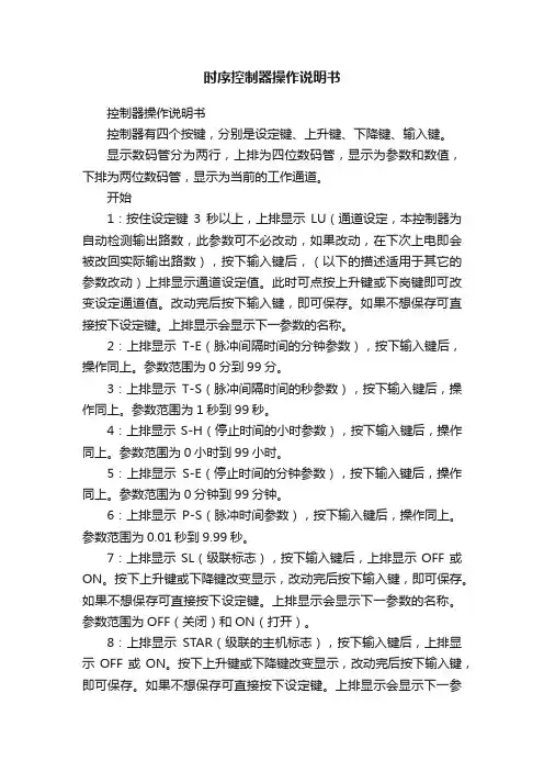
时序控制器操作说明书控制器操作说明书控制器有四个按键,分别是设定键、上升键、下降键、输入键。
显示数码管分为两行,上排为四位数码管,显示为参数和数值,下排为两位数码管,显示为当前的工作通道。
开始1:按住设定键3秒以上,上排显示LU(通道设定,本控制器为自动检测输出路数,此参数可不必改动,如果改动,在下次上电即会被改回实际输出路数),按下输入键后,(以下的描述适用于其它的参数改动)上排显示通道设定值。
此时可点按上升键或下岗键即可改变设定通道值。
改动完后按下输入键,即可保存。
如果不想保存可直接按下设定键。
上排显示会显示下一参数的名称。
2:上排显示T-E(脉冲间隔时间的分钟参数),按下输入键后,操作同上。
参数范围为0分到99分。
3:上排显示T-S(脉冲间隔时间的秒参数),按下输入键后,操作同上。
参数范围为1秒到99秒。
4:上排显示S-H(停止时间的小时参数),按下输入键后,操作同上。
参数范围为0小时到99小时。
5:上排显示S-E(停止时间的分钟参数),按下输入键后,操作同上。
参数范围为0分钟到99分钟。
6:上排显示P-S(脉冲时间参数),按下输入键后,操作同上。
参数范围为0.01秒到9.99秒。
7:上排显示SL(级联标志),按下输入键后,上排显示OFF或ON。
按下上升键或下降键改变显示,改动完后按下输入键,即可保存。
如果不想保存可直接按下设定键。
上排显示会显示下一参数的名称。
参数范围为OFF(关闭)和ON(打开)。
8:上排显示STAR(级联的主机标志),按下输入键后,上排显示OFF或ON。
按下上升键或下降键改变显示,改动完后按下输入键,即可保存。
如果不想保存可直接按下设定键。
上排显示会显示下一参数的名称。
参数范围为OFF (关闭)和ON(打开)。
9:上排显示RST(出厂值恢复标志),按下输入键后,上排显示OFF或ON。
按下上升键或下降键改变显示,改动完后按下输入键,即可保存。
如果不想保存可直接按下设定键。
Sequence Injection ControllerVersion 5.5 Sequence Injection ControllerINSTRUCTION MANUALTYPE ACT-D800Thank you for using YUDO production 感谢贵公司使用YUDO 产品Contents 目录1、Environments ……………………………………………………2使用环境2、Composition of Control Module ……… …………………………2PCB 结构3、Central Processing Unit ……………………………………………2主要控制装置4、Input ………………………………………………………………2输入因素5、Display ……………………………………………………………3显示因素6、Output ………………………………………………………………3输出因素7、Start to Run…………………………………………………………4使用说明8、Menu Setting………………………………………………………5动态说明9、Mode Specification ………………………………………………7模式规格10、System Application ………………………………………………8系统应用程序11、Wiring Specification………………………………………………9外部线连接图Before using the product ,please read this instruction manual carefully to avoid any damage due to improper usage. If you have any questions, please do not hesitate to contact our Head Office or YUDO Territory Sales Branch.使用本产品前,敬请仔细阅读此手册,以免在操作过程中的失误。
电源时序器电源时序器能够按照由前级设备到后级设备逐个顺序启动电源,关闭供电电源时则由后级到前级的顺序关闭各类用电设备,这样就能有效的统一管理和控制各类用电设备,避免了人为的失误操作,同时又可减低用电设备在开关瞬间对供电电网的冲击,也避免了感生电流对设备的冲击,确保了整个用电系统的稳定。
1产品使用说明1.备用电源开关:可以用来防止控制器因某些原因而失去控制,关掉此开关,可同时连接所有插座电源;2.输出插座指示灯:当每个指示灯亮相对应插座将连通电源; 3.电源指示灯:打开此电源控制器后,指示灯就会显示已经启动的控制信号;4.电源开关:打开此电源开关时,就会自动按照:1~8顺序把电源输入插座中。
关掉此电源,就会自动按照:8~1此顺序把电源切断;5.电源输入电缆;6.电源输出插座。
2功能与使用1.此电源开关打开时,控制器可以按顺序连接到每一个插座。
相反地,关掉此电源开关,控制器可以反顺序切断每一个插座上的电源。
2.此装置可以用作会议中心,电脑机房,电视播放系统与其他电源系统,都需要按照顺序的打开设备。
3技术规格1.每一路输出电流15A;2.控制电源:8通道;4RS232/RS485串口控制RS232(3脚接收,5脚信号地)RS485(3脚B,5脚A)波特率9600数据位8停止位1校验位None每接收正确的串口命令,电源指示灯闪烁三次,频率为0.5秒/次。
A0是修改ID(00)地址码。
00是固定公共地址码,例如ID是01指令是CA 20 00 A0 01 ACA1各路开关例如:第一路开:CA 20 00 A1 11 AC 关:CA 20 00 A1 10 AC 第二路开:CA 20 00 A1 21 AC 关:CA 20 00 A1 20 AC 第三路开:CA 20 00 A1 31 AC 关:CA 20 00 A1 30 AC 第十路开:CA 20 00 A1 A1 AC 关:CA 20 00 A1 A0 AC 第十一路开:CA 20 00 A1 B1 AC 关:CA 20 00 A1 B0 AC 第十二路开:CA 20 00 A1 C1 AC 关:CA 20 00 A1 C0 AC 全开:CA 20 00 A1 F1 AC全关:CA 20 00 A1 F0 AC各路上锁与解锁指令:(是上锁对应路开关,不受开关锁控制)如:第一路上锁:CA 20 00 A3 11 AC解锁:CA 20 00 A3 10 AC开关锁上锁与解锁指令:上锁:CA 20 00 A5 F1 AC 解锁:CA 20 00 A5 F0 AC 清除所有指令CA 20 00 A6 F1 AC。
时序控制器操作說明一、 用途顺序时间控制器是用于使用阀针式热流道系统时,用以控制模具热咀注塑时间先后的设备。
顺序时间控制器能使热流道系统的各个浇口得以控制,具有以下优势:·使成形产品表面引发瑕疵的熔接痕消除,或重新设置产品表面熔接痕的位置,从而达到改善成形产品的质量;·通过对每一个浇口的注射量的调节,达到改善品质,以防产品瑕疵出现或产品填充未到位等现象的发生;·受时间控制器的控制,所有的浇口并不是同时开放,故注塑可在最小锁模力的情况下进行;·通过浇口处注射率的提高,使产品流痕达到最佳状态。
二、电源配置主电源输入单相交流电95-240VAC50/60HZ注射信号输入直流24VDC、交流110V/220V、开关信号可选电磁阀电压直流24VDC、交流110V/220V、操作温度范围(-10 - +50度)PCB结构 1.PCB主板 2.显示PCB板时间控制器电源注塑信号输入,注射信号输出。
切换信号输入,状态显示。
三、面板操作說明A —蜂鸣器B —A模式指示灯C —B模式指示灯D —显示关闭时间E —显示开启时间F —关闭指示灯G —打开指示灯H —待机指示灯J —设定值调节功能键(上)K —设定值调节功能键(下)I —手动键L —参数设置键M —电源开关键N —模式信息对照表二.时序控制器操作步骤。
1.按ON/OFF键打开时序控制卡电源,2.功能参数设置,1>A/B模式设置按住MODE SET键1秒进入参数设置,上端显示器会显示A-B,下端显示器显示模式A或B,通过按上键或下键可调整为B模式或A模式;按按住MODE SET 键1秒可退出参数设置。
2>0.1与0.01秒定时分辨率选择按住MODE SET键1秒进入参数设置,上端显示器会显示A-B,下端显示器显示模式A或B,然后再点击MODE SET键1次,此时上端显示器会显示dot, 下端显示器分辨率0.01或0.1,通过按上键或下键可调整分辨率为0.1或0.01;按住MODE SE T键1秒可退出参数设置。
400V ACTIVE OR-ING MOSFET CONTROLLER IN SO7DescriptionThe ZXGD3112N7 is a 400V active ORing MOSFET controller designed for driving a very low R DS(ON) power MOSFET as an idealdiode. This replaces the standard rectifier to reduce the forward voltage drop and overall increase the power transfer efficiency.The ZXGD3112N7 can be used on both high-side and low-side power supply units (PSU) with rails up to ±400V. It enables very low R DS(ON) MOSFETs to operate as ideal diodes as the turn-off threshold is only -3mV with ±2mV tolerance. In the typical 48V configuration, the standby power consumption is <50mW as the low quiescent supply current is <1mA. During PSU fault condition, the ORing controller detects the power reduction and rapidly turns off the MOSFET in <600ns to block reverse current flow and avoid the common bus voltage dropping.ApplicationsActive ORing Controller in:• (N + 1) Redundant Power Supplies • Telecom and Networking • Data Centers and ServersFeatures• Active OR-ing MOSFET Controller for High- or Low-Side PSU • Ideal Diode to Reduce Forward Voltage Drop• -3mV Typical Turn-Off Threshold with ±2mV Tolerance • 400V Drain Voltage Rating • 25V V CC Rating• <50mW Standby Power with Quiescent Supply Current <1mA • <600ns Turn-Off Time to Minimize Reverse Current• Totally Lead-Free & Fully RoHS Compliant (Notes 1 & 2) • Halogen and Antimony Free. “Green” Device (Note 3)Mechanical Data• Case: SO-7• Case Material: Molded Plastic. “Green” Molding Compound. UL Flammability Rating 94V-0• Moisture Sensitivity: Level 1 per J-STD-020• Terminals: Finish—Matte Tin Plated Leads, Solderable per MIL-STD-202, Method 208 • Weight: 0.074 grams (Approximate)Ordering Information (Note 4)Product Marking Reel Size (inches)Tape Width (mm)Quantity per ReelZXGD3112N7TCZXGD311213122500Notes:1. No purposely added lead. Fully EU Directive 2002/95/EC (RoHS), 2011/65/EU (RoHS 2) & 2015/863/EU (RoHS 3) compliant.2. See https:///quality/lead-free/ for more information about Diodes Incorporated’s definitions of Halogen- and Antimony-free, "Green" and Lead-free.3. Halogen- and Antimony-free "Green” products are defined as those which contain <900ppm bromine, <900ppm chlorine (<1500ppm total Br + Cl) and <1000ppm antimony compounds.4. For packaging details, go to our website at /products/packages.html.Marking InformationTop ViewSO-7Top View Pin-OutGATEGNDPGNDGND VccPGND DRAIN1 234567ZXGD = Product Type Marking Code, Line 1 3112 = Product Type Marking Code, Line 2 YY = Year (ex: 18 = 2018) WW = Week (01 to 53) ZXGD 3112 YY WWPin FunctionsPin NumberPin Name Pin Function and Description1, 2 GND GroundConnect this pin to the MOSFET source terminal and ground reference point. 3 V CC Power SupplyThis supply pin should be closely decoupled to ground with a X7R type capacitor. 4 GATE Gate DriveThis pin sources (I SOURCE ) and sinks (I SINK ) current into the MOSFET gate. If V CC > 12V, then the GATE-to-GND will clamp at 12V. The turn on time of the MOSFET can be programmed through an external gate resistor (R G ). 5, 6 PGND Power GroundConnect this pin to the MOSFET source terminal and ground reference point. 7 DRAINDrain SenseConnect this pin to the MOSFET drain terminal to detect the change in drain-source voltage.**Gate voltage is clamped to 12V.Thermal CharacteristicsCharacteristicSymbolValue UnitPower DissipationLinear Derating Factor(Note 5)P D 490 3.92 mW mW/°C(Note 6) 655 5.24 (Note 7) 720 5.76 (Note 8)7856.28 Thermal Resistance, Junction to Ambient (Note 5) R ϴJA 255 °C/W (Note 6) 191 (Note 7) 173 (Note 8) 159 Thermal Resistance, Junction to Lead (Note 9)R ϴJL 135 °C/W Operating and Storage Temperature Range T J , T STG-50 to +150°C(Note 10)Notes:5. For a device surface mounted on minimum recommended pad layout FR-4 PCB with high coverage of single sided 1oz copper, in still air conditions; the device is measured when operating in a steady-state condition.6. Same as Note 5, except pin 3 (V CC ) and pins 5 & 6 (PGND) are both connected to separate 5mm × 5mm 1oz copper heat-sinks.7. Same as Note 6, except both heat-sinks are 10mm × 10mm.8. Same as Note 6, except both heat-sinks are 15mm × 15mm.9. Thermal resistance from junction to solder-point at the end of each lead on pins 2 & 3 (GND) and pins 5 & 6 (V CC ). 10. Refer to JEDEC specification JESD22-A114 and JESD22-A11.Thermal Derating CurveDerating CurveJunction Temperature (OC)M a x P o w e r D i s s i p a t i o n (W )Electrical Characteristics (@ V CC = 12V, T A = +25°C, unless otherwise specified.)CharacteristicSymbol Min Typ Max Unit Test ConditionInput SupplyOperating Supply Voltage V CC 4 — 20 V —Quiescent CurrentI Q — 260 400 µA -0.6V ≤ V DRAIN ≤ 400V Drain Low Input Current I DL -100 -15 — nA V D = -0.1V Drain High Input Current I DH — 0.85 10 µA V D = 400V Gate DriverGate Peak Source Current I SOURCE — 0.66 — A C L = 47nFGate Peak Sink CurrentI SINK — 3.3 — Gate Peak Source Current (Note 11) I SOURCE 1 — — A V GATE = 5V &V DRAIN = -1V Gate Peak Sink Current (Note 11) I SINK 1.8 — — A V GATE = 5V & V DRAIN = 1V Detector Under DC Condition Turn-Off Threshold VoltageV T -5 -3 -1 mVV G ≤1VLoad: 50nF capacitor connected in parallel with 50k Ω resistorGate Output VoltageV G(OFF) — 0.1 0.3 VV DRAIN ≥ 0mV & V CC = 12VV G 10.5 10.85 — V DRAIN = -8mV & V CC = 12VV G(OFF)— 0.1 0.3V DRAIN ≥ 0mV & V CC = 4VV G 2.5 2.85 — V DRAIN = -8mV & V CC = 4VV G(OFF) — 0.1 0.3 V DRAIN ≥ 0mV & V CC = 20VV G10.5 11.2 — V DRAIN = -8mV & V CC = 20VSwitching Performance Turn-On Propagation Delay t D(RISE) — 400 — nsC L = 47nFRise and Fall Measured 10% to 90% Refer to Application Test Circuit BelowGate Rise Timet R — 695 — Turn-Off Propagation Delay t D(FALL)— 400 — Gate Fall Timet F—131—Note:11. Measured under pulsed conditions. Pulse width = 300μs. Duty cycle ≤ 2%.Layout ConsiderationsThe GATE pin must be close to the MOSFET gate to minimize trace resistance and inductance to maximize switching performance while the V CC to GND pin requires an X7R type capacitor closely decoupling the supply. Trace widths must be maximized in the high current paths through the MOSFET and ground return in order to minimize the effects of circuit resistance and inductance. Also, the ground return loop must be as short as possible. For thermal consideration, the main heat path is from pin 3 (V CC) and pins 5 & 6 (PGND). For best thermal performance, the copper area connected to pin 3 (V CC) and pins 5 & 6 (PGND) must be maximized.Active ORing or (N+1) Redundancy ApplicationOR-ing RectifierFigure 1Critical systems require fault-tolerant power supply that can be achieved by paralleling two or more PSUs into (N+1) redundancy configuration. During normal operation, usually all PSUs equally share the load for maximum reliability. If one of the PSU is unplugged or fails, the other PSUs fully support the load. To avoid the faulty PSU from affecting the common bus, an ORing rectifier blocks the reverse current flow into the faulty PSU. Likewise during hot-swapping, the ORing rectifiers isolate a PSU’s discharged output capacitors from the common bus.As the load current is in the tens of amps, a standard rectifier has a significant forward voltage drop. This both wastes power and significantly drops the potential on low voltage rails. Hence, very low R DS(ON) power MOSFETs can replace the standard rectifiers, and the ZXGD3112 controls the MOSFET as an ideal diode.Functional Block DiagramGATE VccDRAINPGNDFigure 2The device is comprised of a differential amplifier and high current driver. The differential amplifier acts as a detector and monitors the DRAIN-to-GND pin voltage difference. When this difference is less than the threshold voltage (V T ), a positive output voltage approaching V CC is given on the GATE pin. If V CC> 12V, the GATE-to-GND clamps at 12V. Conversely, when the DRAIN-to-GND pin voltage difference is greater than V T , the GATE pin voltage rapidly reduces towards the GND voltage.Typical Application CircuitsThe focus application of the ZXGD3112 ORing controller is for redundant low-side -200v power supply rail (see Figure 3). HV to 12V regulator or a potential divider is recommended to power the V CC of ZXGD3112 from high voltage lines.Figure 3Figure 4 shows an example of the ZXGD3112 oring controller in a redundant high-side +200V power supply rail using an additional V CC supply.Figure 4ZXGD3112N7Operation in Typical ApplicationThe ZXGD3112 operation is described step-by-step with reference to the typical application circuits and the timing diagram is shown in Figure 5:1. The ZXGD3112 differential amplifier monitors the MOSFET’s drain-source voltage (V DS ).2.At system start up, the MOSFET body diode is forced to conduct current from the input PSU to the load and V DS is approximately -0.6V as measured by the differential amplifier between DRAIN-to-GND pins. 3.As V DS < V T (threshold voltage), the differential amplifier outputs a positive voltage approaching V CC with respect to GND. This feeds the driver stage from which the GATE pin voltage rises towards V CC . If V CC > 12V, the GATE-to-GND will clamp at 12V. 4. The sourcing current out of the GATE pin drives the MOSFET gate to enhance the channel and turn it on. 5. If a short condition occurs on the input PSU, it causes the MOSFET V DS to increase.6.When V DS > V T , the differential amplifier’s output goes to GND and the driver stage rapidly pulls the GATE pin voltage to GND, turning off the MOSFET channel. This prevents high reverse current flow from the load to the PSU, which can pull down the common bus voltage causing catastrophic system failure.MOSFET Drain VoltageV DSMOSFET Gate VoltageV GSMOSFET Drain Currentt D(RISE)V TVGND t R t Ft D(FALL)I DV GNDV CC0A-0.6VFigure 5ZXGD3112N7ZXGD3112N7Typical Electrical Characteristics0246810-2.0-1.8-1.6-1.4-1.2-1.0-0.8-0.6-0.4-0.20.04008001200160020001002003004005002468101214161820Transfer CharacteristicV G G a t e V o l t a g e (V )V D Drain Voltage (mV)Transfer CharacteristicV G G a t e V o l t a g e (V )V D Drain Voltage (mV)Drain Sense Voltage vs Tem peratureV D D r a i n V o l t a g e (m V )Temperature (OC)Switching vs Tem peratureS w i t c h i n g T i m e (n s )Temperature (OC)Supply Current vs Capacitive LoadCapacitance (nF)S u p p l y C u r r e n t (m A )Transfer CharacteristicV G G a t e V o l t a g e (V )V D Drain Voltage (mV)Typical Electrical Characteristics(continued)-150-100-50050100150Switch O ff SpeedG a t e V o l t a g e (V )Time (µs)D r a i n V o l t a g e (m V )D r a i n V o l t a g e (m V )Switch O n SpeedG a t e V o l t a g e (V )Time (µs)Switching vs Capacitive LoadT i m e (n s )Capacitance (nF)Sink Current Time Scale (µs)G a t e D r i v e S i n k C u r r e n t (A )G ate Drive CurrentG a t e D r i v e S o u r c e C u r r e n t (A )Source Current Time Scale (µs)G ate Current vs Capacitive Load P e a k D r i v e C u r r e n t (A )Capacitance (nF)Supply Current vs FrequencyFrequency (Hz)Package Outline DimensionsPlease see /package-outlines.html for the latest version.SO-7SO-7Dim Min Max Typ A2 1.40 1.50 1.45 A1 0.10 0.20 0.15 b 0.30 0.50 0.40 c 0.15 0.25 0.20 D 4.85 4.95 4.90 E 5.90 6.10 6.00 E1 3.80 3.90 3.85 E1a 3.85 3.95 3.90 e — — 1.27 h — — 0.35 L 0.62 0.82 0.72 Q 0.60 0.70 0.65 All Dimensions in mmSuggested Pad LayoutPlease see /package-outlines.html for the latest version.SO-7DimensionsValue(in mm) C 1.270 X 0.802 X1 4.612 Y1.505 Y1 6.500。
2.65(67.3 mm) 8.802Leviton Mfg. Co., Inc.59-25 Little Neck Pkwy • Little Neck, NY 11362-2591 • Tech Line: 1-800-824-3005 • Fax: 1-800-832-9538Visit our Website at: D3206-1D3206-2The D3206 offers programming capabilitiesincluding each individual zone’s minimum level and name. Scene changes can be scheduled via a series of intuitive Dimensions wizards. Schedules may be based on clock time, or dawn and dusk and can be programmed for daily, weekly and monthly events.As part of a much larger family of digital controls and systems, the D3206 can communicate with other LCnet control stations across its high-speed serial data line. This allows it to be incorporated into asystem with other Dimensions 3200 Zone and Scene Controllers, including the D3204 and D3208 Zone Controller/Dimmers.FEATURES & BENEFITSUser Interface•Wizard menus guide programmer and end-user •Two-line, 32-character LCD (Liquid Crystal Display)•LED Light Level Indicators•Group raise/lower pushbutton for changing all zone light levels at the same time•Zone information buttons that provide zone number, active Zone Controller panel (address), zone type, group number, and brightness level•Compatible with other D3200 components that interface with the system: PC-based programming through D3200 Setup Software and Leviton SmartJack, a wall-mounted Scene Controller, and a handheld remote control and Scene/Auxiliary Power Extenders for extra zone control System•Low-voltage, Class 2 wiring connects multiple zone controllers, wall stations, and control interfaces •Links up to 186 zones•Powers LCnet wall controllers and Leviton SmartJack •Non-volatile memory•Setup Software can be used for system backup and restore—enabling devices to be cloned•Terminating Connector and Low Voltage insulation included Local & Remote Zones•Six dimmable, local zones per controller•Remote zones attached to other Zone Controllers can be controlled•Individual raise/lower pushbuttons for each zone•Customizable 16-character-maximum zone names•Easy programming of minimum level for individual zones •Individual zones may be locked so that their brightness levels cannot be changed•Auxiliary Power Extenders for extra zone control Scene Control•Capable of 32 scenes from the front panel; 8 at one time •Customizable 16-character-maximum scene names •Individual zones may be excluded from specific scenes •System may be locked to a specific scene so that pushing other scene buttons will have no effect•Smooth fading between scenes at configurable, scene-specific fade rates between 0 and 59 seconds or 1 and 120 minutes •"Auto OFF" energy-saving feature complies with California Title 24requirements. Auto OFF automatically turns all lights OFF after a user-defined time interval (up to 2 hours) has elapsed. Auto OFF Start and Stop times are programmed in the Timers menu. Lights will blink at maximum brightness as a warning before they are switched OFF. Pressing a Scene or Zone Dim/Bright button will override OFF switching. After an override, Auto OFF sequence restarts and all lights will be turned OFF after the selected time interval elapses.Scheduled Scene Changes/Clock•Up to 64 scheduled scene changes to adjust lighting based on time of day or astronomical clock can be programmed•Incorporates astronomical clock that can time scene changes based on dawn or dusk, with an optional offset for more random scheduling•Scheduling may be set for weekdays, weekends, holidays or other special events, as well as on daily or weekly bases•Real-time clock retains correct time for two weeks without power •“Auto OFF” Start time and Stop time1A 2A 3A 4A 5A 6ADim ScenePage ZonesCancel Previous Select Next Wizards Menus 2-Line, 16-Character LCDZone InformationIR ReceiverFunction Buttons for Navigation through LCD WizardsScene Programming & RecallMax Bright & OffDim/Brighten(left-most button = Group Dim/Bright)JOB NAME:JOB NUMBER:CATALOG NUMBERS:SPECIFICATION SUBMITTAL3Leviton Mfg. Co., Inc.59-25 Little Neck Pkwy • Little Neck, NY 11362-2591 • Tech Line: 1-800-824-3005 • Fax: 1-800-832-9538Visit our Website at: Infrared Receiver•Learns up to 32 IR commands•Compatible with any standard IR remote •Default to work with NE210 remote controlSPECIFICATIONSElectrical D3206-1Input Voltage: 120VAC ±10%, 50-60Hz Isolated Output: 24VDC @ 150mAOutput Power: 1920W/VA total output, 1000W/VA max per zone,1200W/VA max per sideTesting/Code Compliance: UL Listed, CSA Certified, FCC Part 15,California title 24Lightning Strike Protection: Meets ANSI/IEEE standard 62.41-1980Electrostatic Discharge: Meets IEC 801-2. Tested to withstand 15kV ESD without damage or memory lossSurge Protection: Withstands voltage surges up to 6000V and current surges up to 3000A D3206-2Input Voltage: 230VAC ±10%, 50-60Hz Isolated Output: 24VDC @150mAOutput Power: 2400W/VA total, 800W per zone Testing/Code Compliance: CESources/Load TypesOperates Incandescent, Tungsten, Magnetic Low Voltage Transformer,Advance Mark 10™ Powerline Electronic Fluorescent Dimming Ballast,Neon, Cold Cathode, and non-dimming loadsPower Extenders available to increase load rating as well as increase the types of loads controlled PhysicalSize: 4.73 x 8.80 x 2.65in. (12.0 x 22.4 x 6.7cm)Color: White Frame/White Cover, Black Face, Gray and Translucent Buttons. For other colors, order Cat. No. D32CK Color Change Kit and add suffix as follows: Ivory Frame/Ivory Cover (-II), White Frame/White Cover (-WW), Almond Frame/Almond Cover (-AA),Gray Frame/Gray Cover (-GG), Black Frame/Black Cover (-EE), White Frame/Smoke Cover (-SW).EnvironmentalOperating Temperature Range: 0ºC to +40ºC Storage Temperature Range: -10ºC to +85ºC Relative Humidity: 20% to 90% non-condensing Warranty: Limited 2-Year WarrantyD3206-1D3206-2Power ExtenderAuxiliary Power ExtenderPower Extender Smart JackScene ControllerLCnet (2 pair Cat-5 wires)*NOTE: First and last nodes (devices) on LCnet must be terminated.**JOB NAME:JOB NUMBER:CATALOG NUMBERS:SPECIFICATION SUBMITTAL4D3206-1D3206-2Leviton Mfg. Co., Inc.59-25 Little Neck Pkwy • Little Neck, NY 11362-2591 • Tech Line: 1-800-824-3005 • Fax: 1-800-832-9538Visit our Website at: INSTALLATIONHigh-Voltage Class 1 Wiring•Connect wires in junction box using standard wiring practices.•Pull power wiring from distribution panel and to light fixtures.•Each line voltage terminal can accept up to two #12 AWG wires.Low-Voltage Class 2 WiringNOT REQUIRED if installing only one D3206 Zone Controller attached to no more than six zones.•Daisy chain peripheral devices to LCnet bus.•Make connections in junction box no longer than 29ft drop.•Run low voltage wires separately from line voltage.•Use CAT5-type twisted pair wiring.•Terminate first and last node on LCnetMounting•Mount in 4-gang, 2.5-inch-deep switch box with a 4-gang raised cover.•Faceplate snaps on with no visible means of attachment.DIMENSIONS MULTIZONE CONTROLLER / DIMMERGreenNE100LCnet Bus Length ≤ 1640ftDrop Length≤ 29ftNE505Blue/White Green/WhiteBlueLow-Voltage Wires (Plug-in Connector)LOADS 1-3LOADS 4-6GroundLine Neutral JOB NAME:JOB NUMBER:CATALOG NUMBERS:SPECIFICATION SUBMITTALG-6903/C4-10M/rd。
时序控制器使用方法时序控制器是一种常用的控制设备,在封装测试和生产研发等领域广泛应用。
时序控制器的主要功能是对时间、电平、电流等信号进行精确控制,以实现测试或生产过程中的一系列操作。
在使用时序控制器时,需要将其与被测芯片或器件相连,通过输入控制位和时序信号,控制被测芯片或器件的工作状态,并对其进行测试或生产。
时序控制器的使用方法如下:1. 确定被测芯片或器件的工作电压范围和时序规格在使用时序控制器之前,首先需要确定被测芯片或器件的工作电压范围和时序规格。
通常,这些信息可以从被测芯片或器件的数据手册中获取。
并且建议用户在使用时序控制器时,按照被测芯片或器件的规格要求进行设置,以确保测试结果的准确性。
2. 安装并连接时序控制器将时序控制器安装到测试仪器上,并将其与被测芯片或器件相连。
时序控制器的连接方式通常有两种,一种是使用插针连接器连接,另一种则是通过夹子连接器连接。
3. 配置时序控制器的参数在使用时序控制器之前,需要对其进行一定的配置,以满足测试要求。
通常,时序控制器的配置包括时序信号的产生和控制,控制位的设置以及电压和电流的调节等方面。
4. 编写测试程序编写测试程序是使用时序控制器的关键步骤之一。
根据被测芯片或器件的要求,编写相应的测试程序,包括数据输入、时序控制、输出和数据分析等环节。
5. 运行测试程序在编写好测试程序后,用户可以按照测试程序的要求,进行测试操作。
在测试期间,时序控制器将按照预定的时序规格和控制位设置进行精确控制,确保被测芯片或器件在正确的工作状态下进行测试或生产。
6. 分析测试结果在测试完成后,用户需要对测试结果进行分析,以确定被测芯片或器件是否符合规格要求。
测试结果的分析通常包括对数据的处理和图形展示等方面,以帮助用户更加全面和深入地了解被测芯片或器件的工作状态和性能表现。
总之,时序控制器是一种非常重要的测试控制设备,其使用方法相对简单明了,但在使用时还要注意特定情况的处理,以确保测试或生产的准确性和可靠性。
矿产资源开发利用方案编写内容要求及审查大纲
矿产资源开发利用方案编写内容要求及《矿产资源开发利用方案》审查大纲一、概述
㈠矿区位置、隶属关系和企业性质。
如为改扩建矿山, 应说明矿山现状、
特点及存在的主要问题。
㈡编制依据
(1简述项目前期工作进展情况及与有关方面对项目的意向性协议情况。
(2 列出开发利用方案编制所依据的主要基础性资料的名称。
如经储量管理部门认定的矿区地质勘探报告、选矿试验报告、加工利用试验报告、工程地质初评资料、矿区水文资料和供水资料等。
对改、扩建矿山应有生产实际资料, 如矿山总平面现状图、矿床开拓系统图、采场现状图和主要采选设备清单等。
二、矿产品需求现状和预测
㈠该矿产在国内需求情况和市场供应情况
1、矿产品现状及加工利用趋向。
2、国内近、远期的需求量及主要销向预测。
㈡产品价格分析
1、国内矿产品价格现状。
2、矿产品价格稳定性及变化趋势。
三、矿产资源概况
㈠矿区总体概况
1、矿区总体规划情况。
2、矿区矿产资源概况。
3、该设计与矿区总体开发的关系。
㈡该设计项目的资源概况
1、矿床地质及构造特征。
2、矿床开采技术条件及水文地质条件。