二值图像连通域标记算法与代码 收藏
- 格式:docx
- 大小:25.51 KB
- 文档页数:43
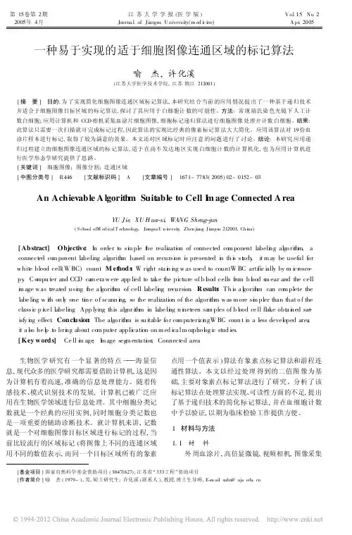
第15卷第2期2005年4月江苏大学学报(医学版)Journa l of Ji angsu U niversity(m ed i c i ne)V o.l15N o.2A pr.2005一种易于实现的适于细胞图像连通区域的标记算法喻杰,许化溪(江苏大学医学技术学院,江苏镇江212001)[摘要]目的:为了实现简化细胞图像连通区域标记算法,本研究结合当前的应用情况提出了一种基于递归技术并适合于细胞图像目标区域的标记算法,探讨了其应用于白细胞计数的可能性。
方法:常规瑞氏染色光镜下人工计数白细胞;应用计算机和CCD相机采集血涂片细胞图像,细胞标记递归算法进行细胞图像处理并计数白细胞。
结果:此算法只需要一次扫描就可完成标记过程,因此算法的实现比经典的像素标记算法大大简化。
应用该算法对19份血涂片样本进行标记,取得了较为满意的效果。
本文还对区域标记时应注意的问题进行了讨论。
结论:本研究应用递归过程建立的细胞图像连通区域的标记算法,适于在尚不发达地区实现白细胞计数的计算机化,也为应用计算机进行医学形态学研究提供了思路。
[关键词]细胞图像;图像分割;连通区域[中图分类号]R446[文献标识码]A[文章编号]1671-7783(2005)02-0152-03 An Achievable A lgorith m Suitable to Cell I m age Connected A reaYU J ie,XU H ua-xi,WANG Sheng-jun(S chool ofM ed icalT echnol ogy,Jiangsu U n i versit y,Zhen ji ang J i angs u212001,Ch i na)[Abstract]Objective:I n order to si m ple t h e realization of connected co m ponent labeli n g algo rithm,a connected co m ponent labeling algorith m based on recursi o n is presented i n th i s st u dy,it m ay be useful for w hite blood cell(W BC)coun.t M et hods:W right sta i n i n g w as used to countW BC artific ially by m icr osco-py.C o mpu ter and CCD ca m era w ere app li e d to take the picture of b l o od cells fro m b l o od s m ear and the cell i m age w as treated usi n g t h e a l g orit h m of cell labeli n g recursion.R esults:Th is a l g orit h m can co m plete the labe li n g w ith on l y one ti m e o f scann i n g,so the realization of the algorithm w as m ore si m pler than that o f the classic p i x e l labeling.App lying this algor ithm in labe li n g n i n eteen sa m ples of b lood ce ll flake obta i n ed sa-t isfy i n g effec.t Concl u sion:The algo rithm is su itable fo r co m puterizi n gW BC coun t i n a less developed area, it a lso he l p to bri n g about co m puter application on m ed ica lm or pho l o g ic stud ies.[Key w ords]Ce ll i m age;I m age seg m enta ti o n;Connected area生物医学研究有一个显著的特点)))海量信息,现代众多的医学研究都需要借助计算机,这是因为计算机有着高速,准确的信息处理能力。

matlab函数_连通区域1、matlab函数bwareaopen──删除小面积对象格式:BW2 = bwareaopen(BW,P,conn)作用:删除二值图像BW中面积小于P的对象,默认情况下使用8邻域。
算法:(1)Determine the connected components.L = bwlabeln(BW, conn);(2)Compute the area of each component.S = regionprops(L, 'Area');(3)Remove small objects.bw2 = ismember(L, find([S.Area] >= P));2、matlab函数bwarea──计算对象面积格式:total = bwarea(BW)作用:估计二值图像中对象的面积。
注:该面积和二值图像中对象的像素数目不一定相等。
3、matlab函数imclearborder──边界对象抑制格式:IM2 = imclearborder(IM,conn)作用:抑制和图像边界相连的亮对象。
若IM是二值图,imclearborder将删除和图像边界相连的对象。
默认情况conn=8。
注:For grayscale images, imclearborder tends to reduce the overall intensity level in addition to suppressing border structures.算法:(1)Mask image is the input image.(2)Marker image is zero everywhere except along the border, where it equals the mask image.4、matlab函数bwboundaries──获取对象轮廓格式:B = bwboundaries(BW,conn)(基本格式)作用:获取二值图中对象的轮廓,和OpenCV中cvFindContours函数功能类似。
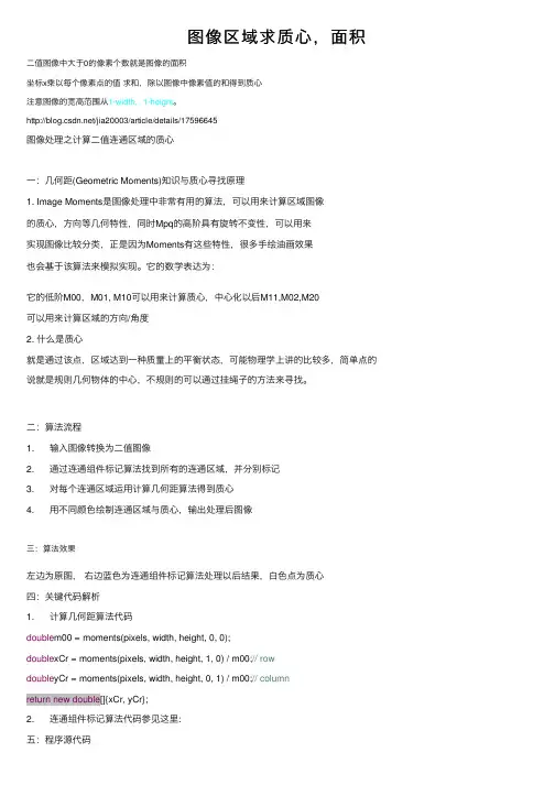
图像区域求质⼼,⾯积⼆值图像中⼤于0的像素个数就是图像的⾯积坐标x乘以每个像素点的值求和,除以图像中像素值的和得到质⼼注意图像的宽⾼范围从1-width,1-height。
/jia20003/article/details/17596645图像处理之计算⼆值连通区域的质⼼⼀:⼏何距(Geometric Moments)知识与质⼼寻找原理1. Image Moments是图像处理中⾮常有⽤的算法,可以⽤来计算区域图像的质⼼,⽅向等⼏何特性,同时Mpq的⾼阶具有旋转不变性,可以⽤来实现图像⽐较分类,正是因为Moments有这些特性,很多⼿绘油画效果也会基于该算法来模拟实现。
它的数学表达为:它的低阶M00,M01, M10可以⽤来计算质⼼,中⼼化以后M11,M02,M20可以⽤来计算区域的⽅向/⾓度2. 什么是质⼼就是通过该点,区域达到⼀种质量上的平衡状态,可能物理学上讲的⽐较多,简单点的说就是规则⼏何物体的中⼼,不规则的可以通过挂绳⼦的⽅法来寻找。
⼆:算法流程1. 输⼊图像转换为⼆值图像2. 通过连通组件标记算法找到所有的连通区域,并分别标记3. 对每个连通区域运⽤计算⼏何距算法得到质⼼4. ⽤不同颜⾊绘制连通区域与质⼼,输出处理后图像三:算法效果左边为原图,右边蓝⾊为连通组件标记算法处理以后结果,⽩⾊点为质⼼四:关键代码解析1. 计算⼏何距算法代码double m00 = moments(pixels, width, height, 0, 0);double xCr = moments(pixels, width, height, 1, 0) / m00;// rowdouble yCr = moments(pixels, width, height, 0, 1) / m00;// columnreturn new double[]{xCr, yCr};2. 连通组件标记算法代码参见这⾥:五:程序源代码[java]1. package com.gloomyfish.image.moments;2.3. import java.awt.image.BufferedImage;4.5. import com.gloomyfish.filter.study.AbstractBufferedImageOp;6. import com.gloomyfish.rice.analysis.FastConnectedComponentLabelAlg;7. // Geometric Moments Computing8. // low-order moments - calculate the center point9. // second-order moments - get angle size10. // projection -11. public class GeometricMomentsFilter extends AbstractBufferedImageOp {12.13. @Override14. public BufferedImage filter(BufferedImage src, BufferedImage dest) {15. int width = src.getWidth();16. int height = src.getHeight();17.18. if ( dest == null )19. dest = createCompatibleDestImage( src, null );20.21. // first step - make it as binary image output pixel22. int[] inPixels = new int[width*height];23. int[] outPixels = new int[width*height];24. getRGB( src, 0, 0, width, height, inPixels );25. int index = 0;26. for(int row=0; row<height; row++) {27. int tr = 0;28. for(int col=0; col<width; col++) {29. index = row * width + col;30. tr = (inPixels[index] >> 16) & 0xff;31. if(tr > 127)32. {33. outPixels[index] = 1;34. }35. else36. {37. outPixels[index] = 0;38. }39. }40. }41.42. // second step, connected component labeling algorithm43. FastConnectedComponentLabelAlg ccLabelAlg = new FastConnectedComponentLabelAlg();44. ccLabelAlg.setBgColor(0);45. int[] labels = ccLabelAlg.doLabel(outPixels, width, height);46. int max = 0;47. for(int i=0; i<labels.length; i++)48. {49. if(max < labels[i])50. {51. System.out.println("Label Index = " + labels[i]);52. max = labels[i];53. }54. }55.56. // third step, calculate center point of each region area(connected component)57. int[] input = new int[labels.length];58. GeometricMomentsAlg momentsAlg = new GeometricMomentsAlg();59. momentsAlg.setBACKGROUND(0);60. double[][] labelCenterPos = new double[max][2];61. for(int i=1; i<=max; i++)62. {63. for(int p=0; p<input.length; p++)64. {65. if(labels[p] == i)66. {67. input[p] = labels[p];68. }69. else70. {71. input[p] = 0;72. }73. }74. labelCenterPos[i-1] = momentsAlg.getGeometricCenterCoordinate(input, width, height);75. }76.77. // render the each connected component center position78. for(int row=0; row<height; row++) {79. for(int col=0; col<width; col++) {80. index = row * width + col;81. if(labels[index] == 0)82. {83. outPixels[index] = (255 << 24) | (0 << 16) | (0 << 8) | 0; // make it as black for background84. }85. else86. {87. outPixels[index] = (255 << 24) | (0 << 16) | (0 << 8) | 100; // make it as blue for each region area88. }89. }90. }91.92. // make it as white color for each center position93. for(int i=0; i<max; i++)94. {95. int crow = (int)labelCenterPos[i][0];96. int ccol = (int)labelCenterPos[i][1];97. index = crow * width + ccol;98. outPixels[index] = (255 << 24) | (255 << 16) | (255 << 8) | 255;99. }100.101. setRGB( dest, 0, 0, width, height, outPixels );102. return dest;103. }104.105. }package com.gloomyfish.image.moments;import java.awt.image.BufferedImage;import com.gloomyfish.filter.study.AbstractBufferedImageOp;import com.gloomyfish.rice.analysis.FastConnectedComponentLabelAlg;// Geometric Moments Computing// low-order moments - calculate the center point// second-order moments - get angle size// projection -public class GeometricMomentsFilter extends AbstractBufferedImageOp {@Overridepublic BufferedImage filter(BufferedImage src, BufferedImage dest) {int width = src.getWidth();int height = src.getHeight();if ( dest == null )dest = createCompatibleDestImage( src, null );// first step - make it as binary image output pixelint[] inPixels = new int[width*height];int[] outPixels = new int[width*height];getRGB( src, 0, 0, width, height, inPixels );int index = 0;for(int row=0; row<height; row++) {int tr = 0;for(int col=0; col<width; col++) {index = row * width + col;tr = (inPixels[index] >> 16) & 0xff;if(tr > 127){outPixels[index] = 1;}else{outPixels[index] = 0;}}}// second step, connected component labeling algorithmFastConnectedComponentLabelAlg ccLabelAlg = new FastConnectedComponentLabelAlg();ccLabelAlg.setBgColor(0);int[] labels = ccLabelAlg.doLabel(outPixels, width, height);int max = 0;for(int i=0; i<labels.length; i++){if(max < labels[i]){System.out.println("Label Index = " + labels[i]);max = labels[i];}}// third step, calculate center point of each region area(connected component)int[] input = new int[labels.length];GeometricMomentsAlg momentsAlg = new GeometricMomentsAlg();momentsAlg.setBACKGROUND(0);double[][] labelCenterPos = new double[max][2];for(int i=1; i<=max; i++){for(int p=0; p<input.length; p++){if(labels[p] == i){input[p] = labels[p];}else{input[p] = 0;}}labelCenterPos[i-1] = momentsAlg.getGeometricCenterCoordinate(input, width, height);}// render the each connected component center positionfor(int row=0; row<height; row++) {for(int col=0; col<width; col++) {index = row * width + col;if(labels[index] == 0){outPixels[index] = (255 << 24) | (0 << 16) | (0 << 8) | 0; // make it as black for background}else{outPixels[index] = (255 << 24) | (0 << 16) | (0 << 8) | 100; // make it as blue for each region area }}}// make it as white color for each center positionfor(int i=0; i<max; i++){int crow = (int)labelCenterPos[i][0];int ccol = (int)labelCenterPos[i][1];index = crow * width + ccol;outPixels[index] = (255 << 24) | (255 << 16) | (255 << 8) | 255;}setRGB( dest, 0, 0, width, height, outPixels );return dest;}}Moment算法代码:[java]1. package com.gloomyfish.image.moments;2.3. public class GeometricMomentsAlg {4. private int BACKGROUND = 0; // background color5. private int labelIndex = 1;6.7. public GeometricMomentsAlg()9. System.out.println("Geometric Moments Algorithm Initialziation...");10. }11.12. public int getLabelIndex() {13. return labelIndex;14. }15.16. public void setLabelIndex(int labelIndex) {17. belIndex = labelIndex;18. }19.20. public int getBACKGROUND() {21. return BACKGROUND;22. }23.24. public void setBACKGROUND(int bACKGROUND) {25. BACKGROUND = bACKGROUND;26. }27.28. public double[] getGeometricCenterCoordinate(int[] pixels, int width, int height)29. {30. double m00 = moments(pixels, width, height, 0, 0);31. double xCr = moments(pixels, width, height, 1, 0) / m00; // row32. double yCr = moments(pixels, width, height, 0, 1) / m00; // column33. return new double[]{xCr, yCr};34. }35.36. public double moments(int[] pixels, int width, int height, int p, int q)37. {38. double mpq = 0.0;39. int index = 0;40. for(int row=0; row<height; row++)41. {42. for(int col=0; col<width; col++)43. {44. index = row * width + col;45. if(pixels[index] == BACKGROUND) continue;46. mpq += Math.pow(row, p) * Math.pow(col, q);47. }48. }49. return mpq;50. }51.52. public double centralMoments(int[] pixel, int width, int height, int p, int q)53. {54. double m00 = moments(pixel, width, height, 0, 0);55. double xCr = moments(pixel, width, height, 1, 0) / m00;56. double yCr = moments(pixel, width, height, 0, 1) / m00;57. double cMpq = 0.0;58. int index = 0;59. for(int row=0; row<height; row++)60. {61. for(int col=0; col<width; col++)62. {63. index = row * width + col;64. if(pixel[index] == BACKGROUND) continue;65. cMpq += Math.pow(row - xCr, p) * Math.pow(col - yCr, q);66. }67. }68. return cMpq;69. }70.71. public double normalCentralMoments(int[] pixel, int width, int height, int p, int q)72. {73. double m00 = moments(pixel, width, height, 0, 0);74. double normal = Math.pow(m00, ((double)(p+q+2))/2.0d);75. return centralMoments(pixel, width, height, p, q)/normal;77. }。
本科生毕业设计二值图像特征提取算法研究Binary Image Feature Extraction Algorithm of Study学院名称:物理与通信电子学院专业名称:通信工程姓名:学号:指导教师:完成日期:摘要本文先简单描述了数字图像及数字图像处理与我们日常生活的联系,接着介绍了二值图像的几何特征和图像特征提取的几种方法,重点以二值图像为例,讲述图像特征提取算法的研究。
首先,文章简单介绍了二值图像的几何特征,详细讲述了二值图像操作中二值形态基本运算的膨胀、腐蚀、开启和闭合运算,并以实例实现了膨胀、腐蚀、开启、闭合等二值操作。
其次,本文研究了膨胀与腐蚀的对偶性。
归纳总结了膨胀和腐蚀算法的原理。
最后,通过示例:“对钢纹的区域标识”,进一步研究二值图像特征提取算法。
关键词:特征提取,二值图像,膨胀,腐蚀。
AbstractThis article described the digital image and digital image processing which connect with our daily life, then introduced binary image geometry characteristic and several methods of image feature extraction and the narrations image feature extraction algorithm research, by the example of the binary images. Firstly, the article introduces the binary image's geometry characteristic then narrato r’s the binary image operations that the binary shape fundamental operation such as the inflation, the corrosion, opening and the closed operation. Secondly, the paper studies the inflation and the corrosion's duality. Finally, summarizing the inflation and the corrosion algorithm principle and going a demonstration:” to corrugate steel region marking”, I study the binary image feature extraction algorithm.Key words: The feature extraction, binary image, the inflation, corrodes.目录摘要 (I)ABSTRACT ........................................................................................................................................... I I 1.引言. (1)1.1背景:数字图像及数字图像处理 (1)2.二值图像的几何特征 (3)3.图像特征提取操作 (3)3.1图像面积 (3)3.2欧拉数 (4)4.二值图像操作 (4)4.1二值形态学基本运算 (5)4.1.1.膨胀 (6)1.膨胀运算的概念 (6)2.结构元素形状对膨胀运算结果的影响 (9)3.膨胀运算的应用 (9)4.1.2腐蚀 (9)1.腐蚀运算的概念 (9)2.结构元素形状对腐蚀运算结果的影响 (11)3.腐蚀运算在物体识别中的应用 (11)4.1.3膨胀与腐蚀的对偶性 (11)1.概述 (11)2.膨胀与腐蚀实现方法(实例) (13)4.1.4开启和闭合运算 (15)1.开启和闭合运算的概念 (15)2.噪声滤除 (17)5.对钢纹的区域标识 (17)6.结束语 (21)参考文献 (22)1.引言随着多媒体和Internet技术的快速发展,图像成为多媒体处理的重要内容。
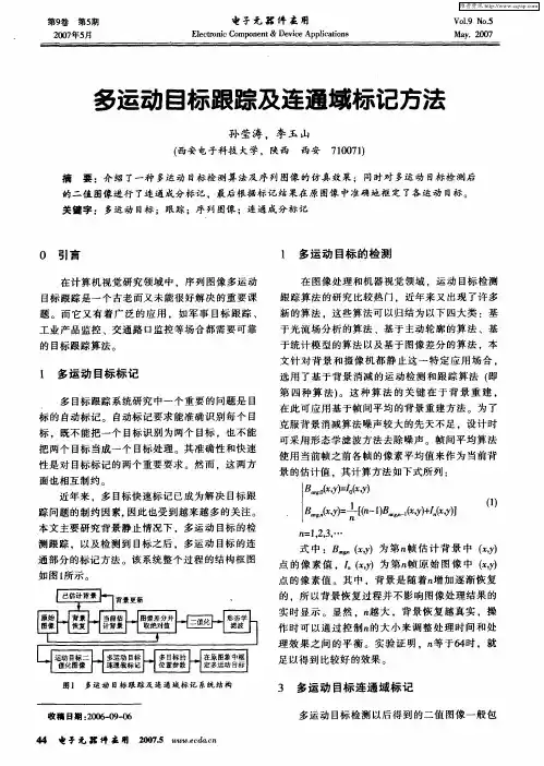
T NOLO GY TR N D1引言提取目标的各种特征量常应用于图像处理,其算法包括像素标记算法、游程连通性算法等。
像素标记算法与游程连通算法不同的是,它不需要事先对图像进行处理,就可以对二值图像进行标记,过程极为简便,但传统的像素标记算法通常需要对二值图像执行二次扫描。
目前,已有很多文献对上述算法进行了改进:文献[1]引入了在区间树上查找的方法,对邻接表和映射表的处理过程做了简化。
文献[2]在像素标记算法的基础上进行了标记矫正,将消除重复标记的操作融入到第一次扫描过程中,使获得的计算结果其等价标记非常少。
文献[3]提出了一种顺序扫描二值图像标记的算法,增加回溯扫描算法对选择的两种典型情况的标记进行处理,并对其他情况的标记冲突进行了分析说明,提高了标记的准确性。
但这些算法最终的连通归属关系要经过不断跟踪扫描,其收敛性有较大震荡。
本文提出了一种改进的算法,它基于区域增长法和线标记法,采用链表进行处理,不会出现标号冲突的情况,并且只需对指针进行操作,非常快捷、简单,为进一步计算目标的其他特征量提供了充分的条件。
2改进的标记算法2.1算法的相关定义1)采用8邻域连通,设A B ,CD 分别为第k 行和k+1行的两条线段,其中A (k ,y0),B (k ,y1),C (k+1,y2),D (k+1,y3)。
两条线段连通的准则是:y2≤y1+1并且y3≥y0-1;2)本文中定义三个链表指针:al_scan_line ,wait_line ,ma rk_li ne ,其中第一个链表用于记录扫描后未进行任何处理的直线段情况。
第二个链表用于记录用于“区域种子”的直线段情况。
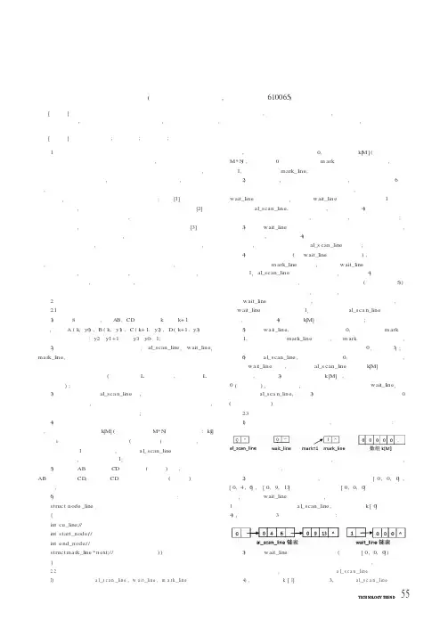
第三个链表是已经标记的直线段链表(如果图像有L 个连通区域,则将产生L 个这样的链表);3)规定直线段链表al_sca n_line 中,各个节点的存取是按照行值从小到大的存取操作,即行值小的插入到行值大的前面。
若行值相同,则按照线段的起始点纵坐标进行存取操作;4)为了标记某行是否已经扫描和记录已扫描行的未处理直线段数目,文中申请了一个数组k [M](图像的大小为M*N )。

连通域的概念引言连通域是计算机图像处理中常用的概念,用于描述图像中相邻像素组成的区域。
在图像分割、目标提取等任务中,连通域可以帮助我们识别并分离出不同的物体和图像区域。
本文将深入探讨连通域的概念及其在图像处理中的应用。
什么是连通域连通域是由相邻的点组成的像素集合,其中的像素具有相同的属性或特征。
在二维图像中,通常将相邻的像素定义为上下左右四个方向具有相同属性的像素。
而在三维图像中,还需要考虑立体方向上的相邻像素。
连通域的特征连通域具有以下特征: 1. 区域内的所有像素具有相同的属性或特征; 2. 区域内的每个像素都与该区域中的至少一个其他像素相邻,即可以通过该区域内的像素进行连通。
连通域的计算方法深度优先搜索(DFS)深度优先搜索是一种遍历连通域的常用方法,在图像处理中也经常使用。
其思想是从一个起始点开始,递归地探索其相邻像素,直到所有相邻像素都被访问过。
其中访问过的像素会被标记为已访问,未访问过的像素则被认为属于一个新的连通域。
广度优先搜索(BFS)广度优先搜索也是一种常用的遍历连通域的方法,在图像处理中同样适用。
不同于深度优先搜索,广度优先搜索是按照距离起始点的路径长度进行遍历。
它从起始点开始,先访问所有与起始点距离为1的像素,然后再访问距离为2的像素,依此类推,直到所有相邻像素都被访问过。
连通域标记法连通域标记法是一种常用的连通域计算方法,其原理是通过扫描整个图像,将属于同一个连通域的像素标记为同一个值。
标记过程可以通过深度优先搜索或广度优先搜索实现。
在使用连通域标记法时,通常需要额外的内存空间来存储已访问过的像素及其标记值。
连通域的应用连通域在图像处理中有广泛的应用,下面将介绍几个常见的应用场景。
目标检测与跟踪在计算机视觉中,目标检测与跟踪是一项重要的任务。
通过分析图像中的连通域,可以将不同的目标或物体提取出来,从而实现目标检测和跟踪。
例如,在视频监控中,可以通过先识别出人体的连通域,再跟踪连通域的运动轨迹,实现人体目标的检测和跟踪。
two pass 连通区域算法两遍算法(Two-pass algorithm)是图像处理中一种用来查找和标记图像中连通区域(或联通分量、区域)的方法。
这种算法首次被提出是在20世纪60年代,如今已成为图像处理中常用的一种方法。
这种算法相对简单而且高效,因此在实际应用中被广泛使用。
在本文中,我们将详细介绍两遍算法的原理和实现过程,并且通过一些示例来说明其应用。
首先,我们需要了解什么是连通区域。
在图像处理中,连通区域是指图像中由相邻像素点组成的一块区域。
在这个区域内的像素点具有相似的性质,比如颜色、亮度等。
通常情况下,我们希望将图像中相互连接的像素点组成的区域识别出来,并进行标记,这样我们就可以在后续的处理中对这些区域进行分析和处理。
两遍算法是一种经典的连通区域查找方法。
其基本思路就是通过两次扫描图像来实现。
在第一次扫描中,我们会遍历整个图像,对每一个像素点进行分析,并进行标记。
在第二次扫描中,我们会对已经被标记的像素点进行进一步处理,比如合并相邻的区域或者进行其他操作。
接下来,我们将详细介绍两遍算法的具体步骤。
第一步:初始化在进行第一次扫描之前,我们需要对一些变量进行初始化。
首先,我们需要一个数组来存储每个像素点的标记。
通常情况下,我们会使用一个与图像大小相同的数组来存储这些标记。
其次,我们需要设定一个阈值,用来确定两个像素点是否属于同一个区域。
最后,我们还需要定义一个函数,用来判断两个像素点是否相邻。
在大多数情况下,我们会使用四邻域或者八邻域来进行判断。
第二步:第一次扫描在第一次扫描中,我们会遍历整个图像,并对每一个像素点进行分析。
首先,我们会检查当前像素点是否已经被标记。
如果已经被标记,我们会继续遍历下一个像素点;如果没有被标记,我们将对该像素点进行标记,并进一步对相邻的像素点进行分析。
通过这种方式,我们就可以逐步找到图像中所有的连通区域,并对其进行标记。
第三步:第二次扫描在第二次扫描中,我们会对已经标记的像素点进行处理。
matlab连通域提取
Matlab连通域提取是一种基于Matlab编程语言的图像处理技术,主要用于提取数字图像中的连通域。
在数字图像中,连通域是指由像素构成的连续区域,其像素值具有相同或类似的特征。
通过连通域提取技术,可以将数字图像中的目标物体从背景中分离出来,对于目标检测、图像分割、特征提取等应用具有重要意义。
Matlab连通域提取主要分为两种方法:基于二值图像和基于灰
度图像。
基于二值图像的连通域提取方法是将数字图像转化为二值图像后,通过二值图像的形态学运算和区域标记技术来提取连通域。
而基于灰度图像的连通域提取方法是将数字图像转化为灰度图像后,通过阈值分割和灰度区域标记技术来提取连通域。
Matlab连通域提取技术广泛应用于图像处理领域,如医学影像
分析、遥感影像分析、工业自动化等。
同时,Matlab连通域提取技
术也是学习数字图像处理的重要内容之一,对于提高数字图像处理的实践能力具有重要意义。
- 1 -。
二值图像连通域标记算法与代码 收藏 10:19:42二值图像连通域标记算法与代码
这里列举二值图像连通域标记算法包括直接扫描标记算法和二值图像连通域标记快速算法 一、直接扫描标记算法把连续区域作同一个标记,常见的四邻域标记算法和八邻域标记算法。 1、 四邻域标记算法: 1) 判断此点四邻域中的最左,最上有没有点,如果都没有点,则表示一个新的区域的开始。
2) 如果此点四邻域中的最左有点,最上没有点,则标记此点为最左点的值;如果此点四邻域中的最左没有点,最上有点,则标记此点为最上点的值。
3) 如果此点四邻域中的最左有点,最上都有点,则标记此点为这两个中的最小的标记点,并修改大标记为小标记。
2、 八邻域标记算法: 1) 判断此点八邻域中的最左,左上,最上,上右点的情况。 如果都没有点,则表示一个新的区域的开始。
2) 如果此点八邻域中的最左有点,上右都有点,则标记此点为这两个中的最小的标记点,并修改大标记为小标记。
3) 如果此点八邻域中的左上有点,上右都有点,则标记此点为这两个中的最小的标记点,并修改大标记为小标记。
4) 否则按照最左,左上,最上,上右的顺序,标记此点为四个中的一个。 代码实现: #include #include #include //连通区域属性结构 typedef struct tagMarkRegion { std::list MarkPointList;//点列表 RECT rect; }MarkRegion;
//定义MarkMap 结构,用来存放等价对 typedef struct tagEqualMark { int MarkValue1; //标记值 int MarkValue2; //标记值 } EqualMark;
//定义MarkMapping 结构,用来存放标记映射关系 typedef struct tagMarkMapping { int nOriginalMark; //第一次扫描的标记 int nMappingMark; //等价整理之后对应标记 } MarkMapping;
/* 功能说明:八连通标记 参数说明:I,表示图像数据指针 ImageWidth,表示图像宽 ImageHeight,表示图像高 off,表示偏移量 nFlag,表示指定标记 iColorType,表示颜色类型,(黑点,白点) markInfo,表示连通区域属性信息 返回值:连通点数量,int类型 */ int FillAreaFlag33(LPINT I,int ImageWidth,int ImageHeight,long off,int nFlag,int iColorType,MarkRegion &markInfo)
{ bool bNew; RECT rect; int m,n,i,j,k,nDot=1,offset,offtemp,yMin; int dxy[8],x,y; dxy[0]=-ImageWidth-1; dxy[1]=-ImageWidth; dxy[2]=-ImageWidth+1;
dxy[3]=-1; dxy[4]=1;
dxy[5]=ImageWidth-1; dxy[6]=ImageWidth; dxy[7]=ImageWidth+1; rect.left=65535; rect.right=-1; rect.bottom=65535; rect.top=-1; markInfo.MarkPointList.clear(); POINT ptTmp; if(I[off]==iColorType && I[off]!=nFlag)//黑点同时未被标记的情况 { I[off]=nFlag; x=off%ImageWidth; y=off/ImageWidth; ptTmp.x = x; ptTmp.y = y; markInfo.MarkPointList.push_back(ptTmp); if(xrect.left=x; if(x>rect.right) rect.right=x; if(yrect.bottom=y; if(y>rect.top) rect.top=y; } else { return 0; }
for(i=y; i{ bNew=false; yMin=i; for(j=0; j{ offset=i*ImageWidth+j; if(I[offset]==nFlag) { for(k=0; k<8; k++)//八邻域搜索 { if(i==0 && k<=2) continue; if(i==ImageHeight-1 && k>=5) continue; if(j==0 && (k==0 || k==3 || k==5)) continue; if(j==ImageWidth-1 && (k==2 || k==4 || k==7)) continue; offtemp=offset+dxy[k]; if(I[offtemp]==iColorType && I[offtemp]!=nFlag) { I[offtemp]=nFlag; nDot++; m=offtemp/ImageWidth; n=offtemp%ImageWidth; ptTmp.x = n; ptTmp.y = m; markInfo.MarkPointList.push_back(ptTmp); if(n < rect.left) rect.left=n; if(n > rect.right) rect.right=n; if(m < rect.bottom) rect.bottom=m; if(m > rect.top) rect.top=m; y=offtemp/ImageWidth; if(y<=yMin) { yMin=y; if(!bNew) bNew=true; } } } } } if(bNew) { i=yMin-1; } } markInfo.rect.left = rect.left; markInfo.rect.right = rect.right; markInfo.rect.top = rect.top; markInfo.rect.bottom = rect.bottom; return nDot; }
/* 功能说明:四连通标记 参数说明:I,表示图像数据指针 ImageWidth,表示图像宽 ImageHeight,表示图像高 off,表示偏移量 nFlag,表示指定标记 iColorType,表示颜色类型,(黑点,白点) markInfo,表示连通区域属性信息 返回值:连通点数量,int类型 */ int FillAreaFlag22(LPINT I,int ImageWidth,int ImageHeight,long off,int nFlag,int iColorType,MarkRegion &markInfo)
{ bool bNew; RECT rect; int m,n,i,j,k,nDot=1,offset,offtemp,yMin; int dxy[4],x,y; dxy[0]=-ImageWidth; dxy[1]=1; dxy[2]=ImageWidth; dxy[3]=-1; rect.left=65535; rect.right=-1; rect.bottom=65535; rect.top=-1; markInfo.MarkPointList.clear(); POINT ptTmp; if(I[off]==iColorType && I[off]!=nFlag)//黑点同时未被标记的情况 { I[off]=nFlag; x=off%ImageWidth; y=off/ImageWidth; ptTmp.x = x; ptTmp.y = y; markInfo.MarkPointList.push_back(ptTmp); if(xrect.left=x; if(x>rect.right) rect.right=x; if(yrect.bottom=y; if(y>rect.top) rect.top=y; } else { return 0; }
for(i=y; i{ bNew=false; yMin=i; for(j=0; j{