CNIT-CLMM-11068陶瓷内衬复合钢管补充协议最终版
- 格式:doc
- 大小:35.00 KB
- 文档页数:2

BS 7846:2009 BSI 英国标准电缆—受火影响时排放少量烟和腐蚀气体的600/1000V热固绝缘铠装耐火电缆—规范未经英国标准协会许可不得复制,除非版权法允许提高国际标准TMBS 7846:2009 BRITISH STANDARD出版和版权信息文件上显示的英国标准协会(BSI)版权日期表明了此文献最后一次发行的时间。
○C BSI 2009ISBN 978 0 580 66960 6ICS 29.060.20以下是本标准工作的BSI相关参考文献参考GEL/20/17委员会09/30 199575 DC草案评论历次版本1996年9月第一次出版2000年10月第二版2009年9月第三版(目前这个版本)出版后公布修正日期2/ 50BRITISH STANDARD BS 7846:2009内容前言范围规范性引用文件术语和定义电压标示和耐火分类导体绝缘线芯识别成缆衬层铠装护套电缆标示密封圈试验目录试验条件例行试验抽样试验型式试验附录附录A(资料性附录)电缆选择和运行推荐附录B(资料性附录)电缆安装推荐附录C(资料性附录)咨询或订货时需提供的信息附录D(规范性附录)厚度测量附录E(规范性附录)刮磨试验附录F(规范性附录)护套的绝缘电阻常数试验附录G(规范性附录)铠装试验BS 7846:2009 BRITISH STANDARD 附录H(规范性附录)铠装电阻附录I空白附录J(规范性附录)电缆护套的收缩试验附录K(规范性附录)成品电压试验附录L(规范性附录)F2类耐火试验—直径大于20mm电缆的附加规定附录M(规范性附录)兼容性试验附录N(资料性附录)铠装的总横截面积附录O空白附录P(资料性附录)型式试验注意事项附录Q(资料性附录)使用指导参考文献图的目录图E.1—刮磨试验图 L.1 试样的耐火加机械冲击试验安装方法表的目录表1—带厚,钢丝直径和锌层质量表2—试验安排表表3—兼容性要求表4—二芯600/1000V钢丝铠装电缆表5—三芯600/1000V钢丝铠装电缆表6—四芯600/1000V钢丝铠装电缆表7—五芯600/1000V钢丝铠装电缆表8—600/1000V钢丝铠装辅助电缆表9—二芯600/1000V联锁钢带铠装电缆表10—三芯600/1000V联锁钢带铠装电缆表11—四芯600/1000V联锁钢带铠装电缆表12—五芯600/1000V联锁钢带铠装电缆表A.1—交流系统电缆的选择4/ 50BRITISH STANDARD BS 7846:2009表B.1—电缆安装最小弯曲半径表B.2—安装后试验电压表E.1—刮磨试验中施加于电缆上的垂直作用力表G.1—温度校正多因子系数表H.1—二芯、三芯、四芯、五芯电缆的最大钢丝铠装电阻值表H.2—辅助电缆的最大钢丝铠装电阻值表H.3—二芯、三芯、四芯、五芯联锁钢带铠装电缆的最大电阻值表K.1—成品试验电压表N.1—二芯、三芯、四芯、五芯钢丝铠装电缆的铠装钢丝的总横截面积表N.2—铜导体钢丝铠装辅助电缆的铠装钢丝的总横截面积表N.3—二芯、三芯、四芯、五芯电缆的连锁钢带铠装的总横截面积表P.1—烟发散试验表页数总览文件包含封面,扉页,页码i-iv,页码1-48,封底BS 7846:2009 BRITISH STANDARD 前言出版信息本标准由BSI出版,于2009年9月30日开始生效,在GEL/20电线电缆技术委员会的授权下,由GEL/20/17的下属委员会,低压电缆起草编写。
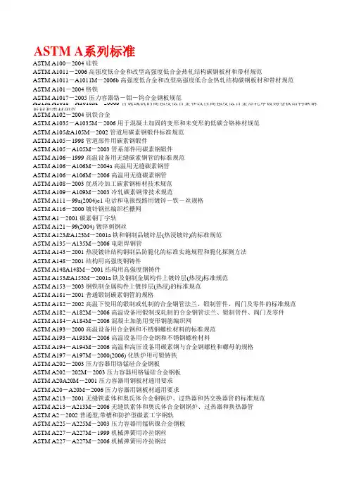
ASTM A系列标准ASTM A100-2004 硅铁ASTM A1011-2006 高强度低合金和改型高强度低合金热轧结构碳钢板材和带材规范ASTM A1011-A1011M-2006b 高强度低合金和改型高强度低合金热轧结构碳钢板材和带材规范ASTM A101-2004 铬铁ASTM A1017-2005 压力容器铬-钼-钨合金钢板规范ASTM A1018-A1018M-2006b含铌或钒的高强度低合金和改性高强度低合金热轧厚镀锡卷板结构碳钢板材和带材规范ASTM A102-2004 钒铁合金ASTM A1035-A1035M-2006 用于混凝土加固的变形和未变形的低碳含铬棒材规范ASTM A105&A105M-2002 管道用碳素钢锻件标准规范ASTM A105-1998 管道部件用碳素钢锻件ASTM A105-A105M-2003 管系部件用碳素钢锻件ASTM A106-1999 高温设备用无缝碳素钢管的标准规范ASTM A106-A106M-2004a 高温用无缝碳素钢管ASTM A106-A106M-2006 高温用无缝碳素钢管ASTM A108-2003 优质冷加工碳素钢棒材技术规范ASTM A109-A109M-2003 冷轧碳素钢带技术规范ASTM A111-99a(2004)e1 电话和电报线路用镀锌-铁-丝规格ASTM A116-2000 镀锌钢丝编织栏栅网ASTM A1-2001 碳素钢丁字轨ASTM A121-99(2004) 镀锌刺钢丝ASTM A123&A123M-2001a 铁和钢制品镀锌层(热浸镀锌)的标准规范ASTM A135-A135M-2006 电阻焊钢管ASTM A143-2001 热浸镀锌结构钢制品防脆化的标准实施规程和脆化探测方法ASTM A148-2001 结构用高强度钢铸件ASTM A148A148M-2001 结构用高强度钢铸件ASTM A153&A153M-2001a 铁及钢制金属构件上镀锌层(热浸)标准规范ASTM A153-2003 钢铁制金属构件上镀锌层(热浸)的标准规范ASTM A181-2001 普通锻制碳素钢管的规格ASTM A182-2002 高温下使用的锻制或轧制的合金钢管法兰、锻制管件、阀门及零件的标准规范ASTM A182-A182M-2006 高温设备用锻制或轧制的合金钢管法兰、锻制管件、阀门及零件ASTM A184-A184M-2006 混凝土加筋用变形钢筋编织网ASTM A193-2000 高温设备用合金钢和不锈钢螺栓材料的标准规范ASTM A193-A193M-2006 高温设备用合金钢和不锈钢螺栓材料ASTM A194-A194M-2006 高温和高压设备用碳素钢与合金钢螺栓和螺母的规格ASTM A197-A197M-2000(2006) 化铁炉用可锻铸铁ASTM A202-2003 压力容器用铬锰硅合金钢板ASTM A202-202M-2003 压力容器用铬锰硅合金钢板ASTM A20A20M-2001 压力容器用钢板材通用要求ASTM A20-A20M-2006 压力容器用钢板材通用要求ASTM A213-2001 无缝铁素体和奥氏体合金钢锅炉、过热器和热交换器管的标准规范ASTM A213-A213M-2006 无缝铁素体和奥氏体合金钢锅炉、过热器和换热器管ASTM A2-2002 普通型,带槽和防护型碳素工字钢轨ASTM A225-A225M-2003 压力容器用锰矾镍合金钢板ASTM A227-A227M-1999 机械弹簧用冷拉钢丝ASTM A227-A227M-2006 机械弹簧用冷拉钢丝ASTM A228-1993 乐器用优质弹簧钢丝标准规范ASTM A234&A234M-2000a 中温与高温设备用锻制碳素钢及合金钢管配件的标准规范ASTM A234&A234M-2005 中温与高温设备用锻制碳素钢及合金钢管配件的标准规范ASTM A239-1995(2004) 用普力斯试验法(硫酸铜浸蚀)确定铁或钢制品上镀锌层最薄点的测试方法ASTM A239-2004 用普力斯试验法(硫酸铜浸蚀)确定铁或钢制品上镀锌层最薄点的测试方法ASTM A240-1994 压力容器用耐热铬及铬镍不锈钢板、薄板及带材ASTM A240-2004a 压力容器用耐热铬及铬镍不锈钢板、薄板及带材ASTM A249-2001 锅炉焊接管ASTM A262-2002ae2 奥氏体不锈钢晶间浸蚀敏感性的检测ASTM A266&A266M-2003 压力容器部件用碳素钢锻件标准规范ASTM A268&A268M-20001 通用无缝和焊接铁素体与马氏体不锈钢管的标准规范ASTM A269-2001 普通设备用无缝和焊接奥氏体不锈钢管标准规范ASTM A27-1995 通用碳素钢铸件ASTM A276-2006 不锈钢棒材和型材1ASTM A27A27M-2000 通用碳素钢铸件ASTM A283A&283M-1998 低和中等抗拉强度碳素钢板标准规范ASTM A290-1995 减速器环用碳素钢和合金钢锻件ASTM A295-2005 高碳耐磨轴承钢技术规范ASTM A29-A29M-1999 热锻及冷加工碳素钢和合金钢棒ASTM A307-2000 抗拉强度为60000PSI的碳素钢螺栓和螺柱的标准规范ASTM A308-2003 经热浸处理镀有铅锡合金的薄板材的技术规范ASTM A309-2001 用三点试验法测定长镀锌薄钢板镀层的重量成分的试验方法ASTM A311-2000 有机械性能要求的消除应力的冷拉碳素钢棒ASTM A312&A312M-2001a 无缝、焊接和深度冷加工奥氏体不锈钢管的标准规范ASTM A31-2004 钢铆钉及铆钉和压力容器用棒材ASTM A312-A312M-2006 无缝和焊接奥氏体不锈钢管ASTM A3-2001(2006) 低、中、高碳素钢鱼尾(连接)板ASTM A320-A320M-2005 低温用合金钢螺栓材料规格ASTM A325M-2000 最小抗拉强度为830Mpa的热处理钢结构螺栓标准规范(米制)ASTM A327M-1991(2006) 铸铁冲击试验方法(米制)ASTM A333&A333M-1999 低温设备用无缝和焊接钢管的标准规范ASTM A333-2004 低温设备用无缝和焊接钢管的标准规范ASTM A335-A335M-2006 高温用无缝铁素体合金钢管ASTM A336-A336M-2006 压力与高温部件用合金钢锻件规格ASTM A338-1994(2004)铁路、船舶和其它重负荷设施在650F(345℃)温度内使用的可锻铸铁法兰、管道配件和阀门零件ASTM A340-2003a 有关磁性试验用符号和定义的术语ASTM A343-2003在电力频率下用瓦特计-安培计-伏特计法(100-1000赫兹)和25厘米艾普斯亭(EPSTEIN) 机架测定材料的交流电磁性能的试验方法ASTM A343-343M-2003在电力频率下用瓦特计-安培计-伏特计法(100-1000赫兹)和25厘米艾普斯亭(EPSTEIN) 机架测定材料的交流电磁性能的试验方法ASTM A345-2004 磁设备用平轧电炉钢ASTM A348-2005用瓦特计-安培计-伏特计法(100-10000赫兹)和25厘米艾普斯亭框测定材料的交流磁性能的试验方法ASTM A34-A34M-2001 磁性材料的抽样和采购试验的标准惯例ASTM A351A315M-2000 压力容器部件用奥氏体和双相奥氏体-铁素体铸件ASTM A351-A351M-2006 容压零件用奥氏体及奥氏体铁素体铸铁的技术规范ASTM A354-2004 淬火与回火合金钢螺栓,双头螺栓及其他外螺纹紧固件规格ASTM A36&A36M-1996 结构碳钢的标准规范ASTM A366e1-1997 冷轧碳钢规范ASTM A370-1996 钢制品机械试验的标准试验方法和定义(中文版)ASTM A370-2003a 钢制品机械试验的标准试验方法和定义ASTM A380-1999(2005) 不锈钢零件、设备和系统的清洗和除垢ASTM A384-2005ASTM A385-2005 提供高质量镀锌覆层(热浸)ASTM A400-69(2006) 钢棒的成分及机械性能选择指南ASTM A403-1997 锻制奥氏体管不锈钢配件标准规范ASTM A403-A403M-2006 锻制奥氏体不锈钢管配件ASTM A409-409M-2001 腐蚀场所或高温下使用的焊接大口径奥氏体钢管ASTM A416-A416M-2006 预应力混凝土用无涂层七股钢铰线ASTM A421 A421M-2005 预应力混凝土用无涂层消除应力钢丝的技术规范ASTM A421-2002 预应力混凝土用无涂层消除应力钢丝的技术规范ASTM A437A&437M-2004 高温设备用经特殊热处理的涡轮型合金钢螺栓材料标准规范ASTM A451-A451M-2006 高温用离心铸造的奥氏体钢管ASTM A47-A47M-1999 铁素体可锻铁铸件ASTM A485-2003 高淬透性耐磨轴承钢的技术规ASTM A48-A48M-2003 灰铁铸件ASTM A49-2001 经热处理的碳素钢鱼尾(连接)板,微合金鱼尾板及锻制碳素钢异型鱼尾板ASTM A494-2004 镍和镍合金铸件ASTM A496-2001 混凝土增强用变形钢丝的标准规范ASTM A512-96 (2001)冷拉对缝焊碳素钢机械管规格标准ASTM A513-2000 电阻焊碳素钢与合金钢机械钢管标准规范ASTM A513-2006 电阻焊碳素钢与合金钢机械钢管ASTM A514M-2000a焊接用经回火与淬火的高屈服强度合金钢板ASTM A514M-2005 焊接用经回火与淬火的高屈服强度合金钢板ASTM A516-A516M-2006 中温及低温压力容器用碳素钢板ASTM A517-2006 压力容器用经回火与淬火的高强度合金钢板ASTM A518–2003 耐蚀高硅铁铸件ASTM A524-1996(2001) 常温和低温用无缝碳素钢管ASTM A530A530M-2004a 特种碳素钢和合金钢管ASTM A532 A532M-1993a(2003) 耐磨铸铁ASTM A53-2002 黑色和热浸镀锌焊接及无缝钢管规范ASTM A53-2006 无镀层热浸的、镀锌的、焊接的及无缝钢管的技术规范ASTM A536-1984(2004) 球墨铸铁件中文版ASTM A537-A537M-2006 压力容器用经热处理的碳锰硅钢板ASTM A540-A540M-2006 特殊用途的合金钢螺栓材料ASTM A541 A541M-2005 压力容器部件用经淬火和回火的碳素钢及合金钢锻件ASTM A553A&553M-1995(00) 压力容器用经回火和淬火的含8%及9%镍的合金钢板的标准规范ASTM A563M-2003 碳合金钢螺母ASTM A564-2004 热轧及冷精轧时效硬化处理过的不锈钢棒材和型材技术规范ASTM A568-A568M-2006 热轧及冷轧高强度低合金碳素钢薄板ASTM A572-2006 高强度低合金钴钒结构钢技术规范ASTM A572-A572M-2006 高强度低合金钴钒结构钢技术规范ASTM A575-1996(2002) 商品级碳素钢棒(M级)ASTM A577 A577M-1990(2001) 钢板的超声角波束检验ASTM A578 A578M-1996(2001) 特殊设备用的普通钢板和包覆钢板的直波束超声探伤检验ASTM A578A578M-2001 特殊设备用的普通钢板和包覆钢板的直波束超声探伤检验的标准规范ASTM A579-2004 超高强度合金钢锻件ASTM A580 A580M-1998 耐热不锈钢丝ASTM A581 A581M-1995b(2000) 高速切削用耐热不锈钢丝和盘条ASTM A581A581M-1995b(2004) 高速切削用耐热不锈钢丝和盘条ASTM A582 A582M-2005 热轧或冷精轧的高速切削不锈及耐热钢棒ASTM A586-1998 镀锌平行和螺旋形钢丝绳ASTM A587-1996(2001) 化学工业用电阻焊低碳钢管ASTM A588 A588M-2004 高强度低合金结构钢4英寸(100mm)厚屈服点最小为50ksi(345MPa) ASTM A589 A589M-2006 水井用无缝和焊接碳素钢管ASTM A6&A6M-1989 轧制结构钢棒材、板材、型材和板桩一般要求的标准规范ASTM A606,656715,JIS G3106,3114中文ASTM A615-A615M-2006 钢筋混凝土配筋用变形和光面坯钢筋ASTM A6-2000 轧制结构钢棒材、板材、型材和板桩一般要求的标准规范ASTM A6-2004 轧制结构钢棒材、板材、型材和板桩一般要求的标准规范(中文)ASTM A633-A633M-2001(2006) 正火的高强度低合金结构钢ASTM A644-1998(R2003) 铁铸件的相关术语ASTM A65-2001 钢轨道钉ASTM A653-A653M-2006 热浸处理的镀锌铁合金或镀锌合金薄钢板的标准规范ASTM A656-2003 具有改良可模锻性的高强度低合金热轧结构钢板ASTM A66-2001 钢质螺旋道钉ASTM A663-A663M-1989(2006) 商品级碳素钢棒的机械特性ASTM A666-奥氏体不锈钢板ASTM A67-2000 热加工低碳钢和高碳钢垫板技术规范ASTM A691-1998(2002) 高温下高压装置用电熔焊碳素钢和合金钢管ASTM A696-2000 压力管道部件专用热锻或冷精轧碳素钢棒ASTM A6-A6M-2006 轧制结构钢板材、型材和薄板桩通用技术要求ASTM A703-2004a 受压部件用钢铸件ASTM A704-A704M-2006 混凝土加筋用焊接普通钢棒或杆的光面钢筋或钢筋网ASTM A706-2006a 混凝土配筋用低合金变形和光圆钢筋ASTM A706-A706M-2006 混凝土配筋用变形低合金光面无节钢筋ASTM A707-2002 低温设备用锻制碳素钢和合金钢法兰ASTM A709-A709M-2006 桥梁用结构钢ASTM A722A&722M-1998 预应力混凝土用未涂覆的高强度钢棒材的标准规范ASTM A732-2002 一般设备用熔模铸造碳素低合金钢及高强度加温钴合金钢铸件ASTM A732A732M-2002 一般设备用熔模铸造碳素低合金钢及高强度加温钴合金钢铸件ASTM A737-1999(2004) 高强度低合金钢压力容器板ASTM A74-2004 铸铁污水管及配件的技术规范ASTM A743A743M-2003 一般用途铁铬、铁铬镍耐腐蚀铸件ASTM A748-1987 压力容器用静态铸造的激冷白口铁-灰口铁双金属轧辊ASTM A754-A754M-2006 X射线荧光涂层厚度的试验方法ASTM A763-2004 铁素体不锈钢晶间腐蚀敏感性检测ASTM A775-A775M-2006 涂环氧树脂的钢筋钢棒ASTM A781-2002 一般工业用一般要求的钢和合金铸件ASTM A781A781M-2002 一般工业用一般要求的钢和合金铸件ASTM A782-A782M-1990[1996] 经淬火和回火的锰铬钼硅锆合金钢压力容器板ASTM A782-A782M-2006 经淬火和回火的锰铬钼硅锆合金钢压力容器板ASTM A795M-2004 防火用黑色及热浸镀锌的焊接和无缝钢管ASTM A796-A796M-2006雨水管和卫生污水管及其它地下埋设管道用波纹钢管、管托架及拱形架结构设计惯例ASTM A800-A800M-2001(2006) 奥氏体合金钢铸件中铁素体含量的估算ASTM A802-A802M-1995(2006) 钢铸件外观检验的表面验收标准ASTM A810-2001 镀锌钢管用绕网ASTM A815-2004 锻制铁素体、铁素体奥氏体和马氏体不锈钢管配件ASTM A817-2003 链接栅栏网用金属涂覆钢丝ASTM A820-A820M-2006 纤维增强混凝土用钢纤维ASTM A82-2002 钢筋混凝土用无节钢丝ASTM A832-1995 压力容器板用铬钼钒及铬钼钒钛硼合金钢ASTM A836-1995 搪瓷管和压力容器设备用钛稳定碳素体钢锻件ASTM A841-2001 压力容器用温度机械控制工艺加工的钢板ASTM A844A844M-1993(1999) 压力容器用直接淬火加工的含镍9%的合金钢板ASTM A887-1989(2004) 核能设备用经硼酸处理的不锈钢板、薄板及带材ASTM A897-A897M-2006 等温淬火球墨铸铁ASTM A90&A90M-2001 镀锌和镀锌合金钢铁制品镀层重量的标准试验方法ASTM A905-1993 压力容器缠绕用钢丝ASTM A917-2006 要求每一面标识有镀层质量用的电解工艺涂层的薄钢板材标准规范ASTM A923-2006 检测锻制双重奥氏体-铁素体不锈钢中有害金属间相的标准试验方法ASTM A946-1995 耐腐蚀和耐热用铬,铬-镍和硅合金钢板,薄板和带的标准规范ASTM A955-A955M-2006a 混凝土增强的变形的和无节钢筋技术规范ASTM A960-A960-2003 普通要求的锻制钢管管件的标准规范ASTM A967-2001 不锈钢零件化学钝化处理的标准规范ASTM A99-2003 锰铁合金ASTM A996-A996M-2006a 混凝土用条钢和车轴钢变形钢棒规范ASTM B 系列标准ASTM B103-1998 锡磷青铜板带材标准ASTM B117-2003 盐雾喷射(雾化)装置操作的标准实施规范 (中文版)ASTM B117-2003 盐雾喷射(雾化)装置操作的标准实施规范(EN)ASTM B117-2003 盐雾喷射装置操作的标准实施规范ASTM B137-1995 阳极镀铝层重量测定的标准试验方法ASTM B148-1997(2003) 铝青铜砂型铸件ASTM B152-152M-2000 铜薄板、带材、中厚板及轧制棒材技术规范ASTM B152M-2006 铜薄板、带材、中厚板及轧制棒材技术规范ASTM B16&B16M-2000 螺纹切削机用易切削黄铜杆材、棒材和型材的标准规范ASTM B16-2005 制螺钉机用易切削黄铜条材、棒材和型材ASTM B164-1998 镍铜合金杆材、棒材和线材标准规范ASTM B166-2004 镍铬铁合金及镍铬钴钼合金条材、棒材及线材ASTM B167-2001 无缝镍铬铁合金管ASTM B168-2001 镍铬铁合金及镍铬钴钼合金板、薄板和带材ASTM B179-2006 砂型铸件、永久型模铸件和压模铸件用铝合金锭及其熔化成形方式ASTM B183-1979(1997) 电镀用低碳钢的制备ASTM B187-B187M-2003 铜汇流棒、条和型材ASTM B208-2004 砂型、永久型、离心型和连续铸造铸件用的铜基合金拉伸试验样件制备标准惯例ASTM B230-B230M-2004 电气用1350-H19型铝线ASTM B231-B231M-2004 同心绞捻铝1350导线ASTM B232-B232M-2001 涂覆钢芯加强的同心绞捻铝导线(ACSR)ASTM B233-2003 电气用1350铝拉制坯料ASTM B234-2004 冷凝器及热交换器用拉制铝和铝合金无缝管ASTM B240-2004 压模铸造用锌及锌铝合金锭ASTM B242-1999(2004)e1 电镀用高碳钢的制备ASTM B249M-2006 铜和铜合金棒材、型材及锻件ASTM B311-1993(2002)e1 孔隙度小于2%的粉末冶金材料密度的标准测试方法ASTM B328-2003 烧结金属结构零件和油浸轴承密度与互连多孔性的试验方法规范ASTM B368-1997(2003) 加速铜氧化的醋酸盐喷雾试验(cass试验)ASTM B36M-2006 黄铜板、薄板、带材及轧制棒材ASTM B380-1997 装饰性电镀层的腐蚀膏试验中文版ASTM B388-2000 恒温双金属薄板和带材ASTM B389-1981(2004) 恒温双金属螺旋形线圈的热偏转率的测试方法ASTM B407-2001 镍铁铬合金无缝管ASTM B423-2005 镍铁铬钼铜合金无缝管ASTM B425-1999 镍铁铬钼铜合金(UNS N08825和UNS N08221)杆材和棒材标准规范ASTM B435-2003统一编制牌号为NO6002、NO6230、N12160和R30556的板材和带材及牌号为N06002、N06230和R30556的带材ASTM B439-2000 铁基烧结轴承(油浸的)ASTM B446-2000 镍铬钼钶合金(UNS N06625)条和棒规范ASTM B446-2003 镍铬钼钶合金(UNS N06625)条和棒规范ASTM B456-1995 铜+镍+铬及镍+铬的电解沉积镀层标准规范ASTM B466 B466M-2003 无缝铜镍合金管ASTM B488-2001(2006) 工程用电解沉积镀金层ASTM B527-1993用塔普-帕克(Tap-Pak)容量计测定金属粉末及化合物粉末的塔普(Tap)密度的标准试验方法ASTM B557-2002a 锻造和铸造的铝及镁合金制品的抗拉试验的标准试验方法ASTM B580-2000 铝阳极氧化镀层ASTM B594-2006 航空用铝合金锻件超声波检测ASTM B604-1991(97) 塑料表面装饰用铜加镍铬镀层标准规范ASTM B619-2005 焊接的镍和镍钴合金管ASTM B626-2004 焊接的镍和镍钴合金管ASTM B633-1998 钢和铁电积沉淀镀锌的标准(中文)ASTM B66-2003 蒸汽机车易损零件用青铜铸件ASTM B670-2002 高温设备用沉淀淬火镍合金(UNS N07718) 厚板、薄板及带材的标准规范ASTM B680-1980(00) 用酸溶解法测定铝的阳极镀层封闭质量的试验方法ASTM B68-2002 光亮退火的无缝铜管ASTM B689-1997(2003) 电镀工程镀镍层ASTM B689-2003 电镀工程镀镍层ASTM B733-2004 化学镀镍ASTM B735-1995(2000) 用硝酸蒸汽测试金属基体上金涂层孔隙度的方法ASTM B748-1990(2006) 用扫描电子显微镜测量横截面测定金属涂层厚度的方法ASTM B824-2004 铜合金铸件ASTM B870-2002 铜-铍合金锻制和挤制合金C17500和C17510的标准规范ASTM B912-2000 用电抛光法测定不锈钢钝化的标准规范ASTM B912-2002 电解抛光ASTM B93-2006 砂型铸件、永久型模铸件和压模铸件用镁合金锭ASTM B94-2005 镁合金压铸件ASTM C 系列标准ASTM C1005-2000 水硬水泥物理试验中质量和体积测定用标准质量与称重器具的标准规范ASTM C1017&C1017M-1998 生产流动混凝土用的化学混合物的标准规范ASTM C1025-2000 石墨电极芯挠曲断裂模数的试验方法ASTM C1038-2004 存放在水中的水硬性水泥灰浆棒膨胀的标准试验方法ASTM C1039-2000 石墨电极的表观孔隙率、表观比重和松密度的试验方法ASTM C1043-2006 使用护热板装置中线电源加热器时稳态热传导特性测量用的加热板温度的测定ASTM C109&C109M-2002ASTM C110-2006 生石灰,熟石灰和石灰石的物理试验方法ASTM C1107-2002 干包装水硬水泥砂浆(非收缩的)标准规范ASTM C113-1993 耐火砖的二次加热变化的标准试验方法ASTM C1134-1990 部分浸入后刚性热绝缘材料水分保持标准试验方法ASTM C114-2004a 水硬水泥化学分析的标准试验方法ASTM C1166-2000 致密及多孔弹性体衬垫和附件火焰蔓延的试验方法ASTM C1179-2000 室外加工碳素材料及石墨材料氧化质量损失试验方法ASTM C1222-2006 实验室试验水硬水泥的评定ASTM C1276-1994 利用旋转米度计测量模制粉末熔点以上粘度的标准试验方法ASTM C1293-2006 用测定碱-硅石反应引起的混凝土长度变化对混凝土集料的标准试验方法ASTM C1305-2006 液体外加防水薄膜的裂缝挖补能力的标准测定方法ASTM C131-2006 用洛杉机磨耗试验机测定小规格粗集料的抗磨性与抗冲击性的试验方法ASTM C1329-2004 砂浆水泥的标准规范ASTM C1398-1998(04)用吉尔摩水泥稠度试验针实验室测定含喷浆混凝土添加剂的水硬水泥砂浆凝固时间的标准试验方法ASTM C1437-2001 水硬水泥灰浆流动性的标准试验方法ASTM C146-1994a(1999) 玻璃沙的化学分析试验方法ASTM C148-2000 玻璃容器偏振检验的试验方法ASTM C149-1986(2000) 玻璃容器热冲击的试验方法ASTM C158-2002 玻璃的挠曲试验方法(测定玻璃挠折模量)ASTM C1587-2006Standard PraASTM CtiASTM Ce for Preparation of Field Removed ManufaASTM Ctured Masonry Units and Masonry SpeASTM Cimens for ASTM Compressive Strength TestingASTM C169-1992(2000) 碱石灰玻璃及硅酸盐玻璃的化学分析试验方法ASTM C170-1990(R1999) 天然建筑石料抗压强度的试验方法ASTM C186(2000) 玻璃容器的内压的试验方法ASTM C-1997 用护热板法测定稳态热通量和传导性的标准试验方法ASTM C224-78(2004)e1 玻璃容器的取样方法ASTM C225-1985(1999) 玻璃容器耐化学腐蚀的试验方法ASTM C24-2001(2006)耐火和高矾土耐溶材料的溶锥当量测试法ASTM C242-2001 卫生陶瓷及其制品术语ASTM C25-2006 石灰石,生石灰和熟石灰的化学分析方法ASTM C270-2006 砌块用的灰浆ASTM C273-2000 夹层结构或夹层芯材的平直剪切性能的试验方法ASTM C305-2006 塑性稠度的水硬性水泥泥浆和灰浆机械搅拌ASTM C32-2004 污水管及检查井用砖(粘土或页岩)ASTM C329-1988(2006) 焙烧卫生陶瓷材料比重的试验方法ASTM C428-05(2006) 石棉水泥无压污水管ASTM C428-2005(2006) 石棉水泥无压污水管ASTM C473-2006 石膏板制品和石膏板条的物理测试标准试验方法ASTM C51-2006 与石灰及石灰石相关的(工业用)名词术语ASTM C518-2004用热流计法测定稳态热通量和热传递特性的试验方法ASTM C559-2000 用物理测量法测定碳加工品及石墨制品松密度的试验方法ASTM C560-1998 石墨的化学分析试验方法ASTM C561-2000 石墨样品中灰分的检测方法ASTM C562-2000 石墨样品中水分的检测方法ASTM C565-1998 碳和石墨机械加工材料抗拉检验的试验方法ASTM C595-2006 混合水硬性水泥ASTM C61(2006)基恩(Keene)石膏水泥ASTM C611-1998 在室温时,炭加工品及石墨制品的电阻率的试验方法ASTM C625-2000 石墨辐射结果的报告ASTM C651-2000 在室温下用四点负荷法,测定炭加工品及石墨制品的抗挠强度的试验方法ASTM C662-1998 不透水的石墨管和插片ASTM C67-2006 砖及结构粘土瓦的取样和试验的试验方法ASTM C695 -2000 碳和石墨和抗压强度的试验方法ASTM C70-2006 细集料表面湿度的测试方法ASTM C704-2001 室温下耐火材料耐腐蚀的试验方法ASTM C709-2003 炭和石墨加工术语ASTM C714-2000 用热脉冲法测定炭和石墨的热扩散系数的测试方法ASTM C747-1998 用音响共振法测定炭精和石墨的弹性模量与基本频率的试验方法ASTM C748-1998 细粒石墨材料的洛氏硬度的测试方法ASTM C749-2002 碳和石墨抗拉应力的试验方法ASTM C769-1998 为获得近似扬氏模量测量加工的炭精及石墨材料中音速的试验方法ASTM C773-1988(2006) 预制封缝带泛油或增塑剂泛出的试验方法ASTM C781-2002 高温气冷核反应堆用试验石墨及硼酸化石墨元部件的标准操作ASTM C783-2003 预制封缝带柔软度的测试方法ASTM C808-2000 炭加工的及石墨制承重材料和密封材料的磨擦及磨蚀结果的报告指南ASTM C816-1998 用燃烧碘量滴定法测定石墨中硫含量的试验方法ASTM C838-2001 加工炭精及石墨型材松密度的试验方法ASTM C880-2006 天然建筑石料弯曲强度的试验方法ASTM C886-1998 细粒炭精和石墨材料肖氏硬度的试验方法ASTM C90-2006a 承重混凝土空心砌块ASTM C94-2004 搅拌好的混凝土规范ASTM C94-2006 搅拌好的混凝土规范ASTM C989-2006 混凝土和灰浆用研磨成颗粒状的高炉碎渣的技术规范ASTM C990-2006 使用预制接缝密封胶粘结的混凝土管道、检查孔和预制箱型型件ASTM C99-1987(R2006) 规格石料断裂模数的试验方法ASTM D 系列标准ASTM D0091-2002润滑油的沉淀值试验方法ASTM D1002-2001 用拉力负载测定金属之间胶粘剂抗剪切强度特性的试验方法ASTM D1002-2005 用拉力负载测定金属之间胶粘剂抗剪切强度特性的试验方法ASTM D1003-1997 ;RASTM DEWMASTM DMTUKVEASTM D1003-2000 ;RASTM DEWMASTM DM-ASTM D1004-1994 ;RASTM DEWMASTM DQTOTRBASTM D1004-1994a R03 ;RASTM DEWMASTM DQTOTRBUJAZASTM D1004-1994a R03 ;RASTM DEWMASTM DQTUKVEASTM D1004-2003 ;RASTM DEWMASTM DQ-ASTM D1004-2003 塑料薄膜和薄板的抗撕裂强度的测试方法ASTM D1005-1995 用千分尺测量有机涂层干膜厚度的试验方法ASTM D1007-2000 仲丁醇ASTM D1007-2005 仲丁醇ASTM D1015-1999高纯烃凝固点测定试验方法ASTM D1015-2004 高纯度烃冻结点的测试方法ASTM D1016-1999 烃纯度试验方法ASTM D1016-2004 冻结点测定烃纯度的试验方法ASTM D1018-2000 石油馏分中氢含量的测试方法ASTM D1018-2000 石油馏分中氢试验方法ASTM D1018-2000(2005) 石油馏分中氢含量的测试方法ASTM D1025-2000 聚合级丁二烯中不挥发性残余物的试验方法ASTM D1025-2000 聚合级丁二烯中固定渣滓试验方法ASTM D1042-1993 ;RASTM DEWNASTM DITOTM-ASTM D1042-2001 ;RASTM DEWNASTM DI-ASTM D1042-2001 ;RASTM DEWNASTM DITMASTM DE-ASTM D1042-2001 ;RASTM DEWNASTM DITUKVEASTM D1043-1999 ;RASTM DEWNASTM DMTOTK-ASTM D1043-1999 ;RASTM DEWNASTM DMTUKVEASTM D1043-2002 ;RASTM DEWNASTM DM-ASTM D1044-1999 ;RASTM DEWNASTM DQ-ASTM D1044-2005 透明塑料表面耐磨蚀性的试验方法ASTM D1045-1995 ;RASTM DEWNASTM DUTOTU-ASTM D1045-1995 R01 ;RASTM DEWNASTM DU-ASTM D1052-1999 用罗斯挠曲装置测定橡胶切口扩展的试验方法ASTM D1053-1997 橡胶特性试验.挠性聚合物和涂覆制品的低温劲度测试方法ASTM D1054-1991 用回跳摆锤法测定橡胶弹性的试验方法ASTM D1055-1997 ;RASTM DEWNTU-ASTM D1056-1998 ;RASTM DEWNTYTUKVEASTM D1056-2000 ;RASTM DEWNTY-ASTM D1062-1996 金属间粘结力抗裂强度的标准试验方法ASTM D1066-2001 蒸汽的抽样方法ASTM D1067-2002 水的酸性和碱性的测试方法ASTM D1068-2003 水中铁的测定ASTM D1068-2003 水中铁的测试方法ASTM D1076-1997 橡胶.浓缩的、氨储存的、乳状的和离心处理的天然胶乳ASTM D1078-2003 挥发性有机液体馏程的测定方法ASTM D1078-2003 挥发性有机液体馏程的试验方法ASTM D1083-1991(98)集装箱、大型船运箱和板条箱的机械搬运的试验方法ASTM D1084-1997 胶粘剂粘度的测试方法ASTM D1091-2000 润滑油和添加剂中磷含量的测试方法ASTM D1091-2000 润滑油及添加剂中磷试验方法ASTM D1092-1999 润滑油可测量表观粘度试验方法ASTM D1092-1999 润滑脂表观粘度的试验方法ASTM D1093-1998 液态烃和它们的蒸馏残余物酸度的测试方法ASTM D1094-00 航空燃料水反应性的试验方法ASTM D1094-2000 航空燃料水反应性的试验方法ASTM D1094-2000 航空燃料易溶于水成分试验方法ASTM D1101-1997a 室外用层压结构木制品的胶合接头完整性的试验方法ASTM D1102-1984(2001)木材中灰分的测试方法ASTM D1125-1999 水的电导性和电阻率的测试方法ASTM D1125-1999 水中的电导和电导率测定法ASTM D1126-2002 水硬度的测试方法ASTM D1126-2002 水中的总硬度 (以 CaCO3计)ASTM D1129-2004 与水相关的术语ASTM D1133-2004 烃类溶剂的贝壳杉脂丁醇值的测试方法ASTM D1141-2003 海水代用品ASTM D1144-1999 胶粘剂粘结强度提高的测定方法ASTM D1146-2000 有效粘结层粘结点的试验方法ASTM D1148-1995 橡胶变质.受热及紫外线使浅颜色表面退色的试验方法ASTM D1149-1999 橡胶变质试验.在小室中橡胶表面臭氧龟裂ASTM D1149-99 橡胶变质试验.在小室中橡胶表面臭氧龟裂ASTM D1151-2000 潮气和温度对胶粘剂粘结能力影响的试验方法ASTM D1152-2001 甲醇(甲基醇)ASTM D1153-2001 甲基异丁基甲酮ASTM D1157-1991 轻烃中TBC测试试验方法ASTM D1157-2000 轻质烃总抑制剂含量(TBC)的测试方法ASTM D1159-2001 电化学滴定法测量石油馏分及商用脂族烯烃的溴值试验方法ASTM D1159-2001 电位滴定法测试石油馏出物和脂肪烃溴数ASTM D1160-2002a 减压蒸馏石油产品试验方法ASTM D1160-2003 石油产品减压蒸馏方法ASTM D116-1986(2006) 电气设备用上釉陶瓷材料的试验ASTM D1171-1999 橡胶变质试验.室外或小室内橡胶表面臭氧龟裂(三角形试样) ASTM D1179-2004 水中氟化物离子的测试方法ASTM D1183-1996 胶粘剂耐周期性实验室老化条件的标准试验方法ASTM D1184-1998 胶粘剂粘结的层压部件抗挠强度的试验方法ASTM D1186-2001 铁基非磁性涂层干膜厚度的无损测量方法ASTM D1192-1998 水和蒸汽的抽样设备标准指南ASTM D1193-1999 试剂水(联邦试验方法No.7916)ASTM D1200-1994(2005) 福特粘度杯测定粘度的试验方法ASTM D1201-1999 ;RASTM DEYMASTM DE-ASTM D1203-1994 R03 ;RASTM DEYMASTM DM-ASTM D1203-1994 R99 ;RASTM DEYMASTM DMTOTRSOTLFMQ--ASTM D1204-1994 ;RASTM DEYMASTM DQTOTRFMQ--ASTM D1204-1994 ;RASTM DEYMASTM DQTUKVEASTM D1204-2002 ;RASTM DEYMASTM DQ-ASTM D1209-2000 透明液体色度的试验方法(铂钴标度)ASTM D1209-2000 无色透明液体色度的测定方法(铂钴标度)ASTM D1210-1996 颜料载体体系分散细度的测试方法ASTM D121-2005 煤和焦炭术语ASTM D1217-1993 宾汗比重瓶测试液体密度试验方法ASTM D1217-1993 用宾汉比重法测定液体密度和相对密度(比重)的试验方法ASTM D1217-2003 用宾汉比重法测定液体密度和相对密度(比重)的试验方法ASTM D1218-2002 碳氢化合物折射率试验方法ASTM D1218-2002 液态烃的折光率和折光分散度的测试方法。
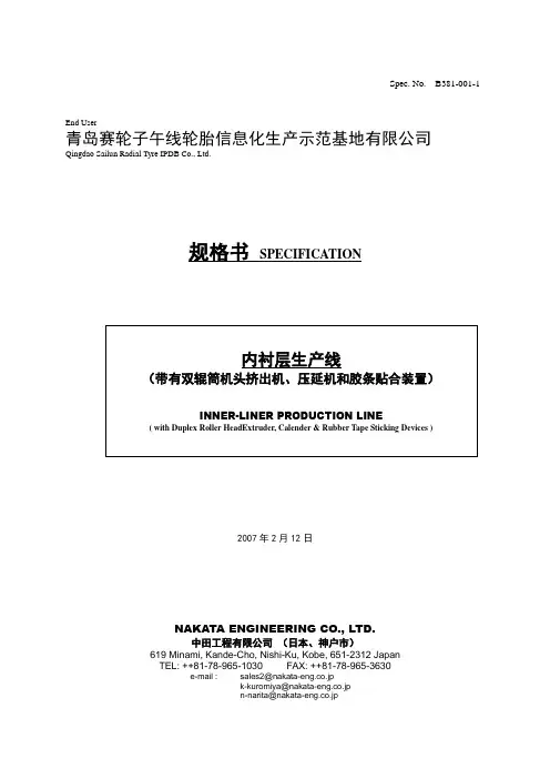
Spec. No. B381-001-1End User青岛赛轮子午线轮胎信息化生产示范基地有限公司Qingdao Sailun Radial Tyre IPDB Co., Ltd.规格书SPECIFICATION2007年2月12日NAKATA ENGINEERING CO., LTD.中田工程有限公司(日本、神户市)619 Minami, Kande-Cho, Nishi-Ku, Kobe, 651-2312 JapanTEL: ++81-78-965-1030 FAX: ++81-78-965-3630e-mail : sales2@nakata-eng.co.jpk-kuromiya@nakata-eng.co.jpn-narita@nakata-eng.co.jp内衬层生产线(带有双辊筒机头挤出机、压延机和胶条贴合装置)INNER-LINER PRODUCTION LINE( with Duplex Roller Head Extruder, Calender & Rubber Tape Sticking Devices )采用本生产线的产品为本规格书A项所描述的轿车胎“双复合内衬层”。
The product with this line is “Duplex Inner Liner Complex” for PCR tyre as stipulated in Item A of this Specification.为便于理解,请参见下页中所附的工艺流程图。
For easy understanding please refer to the process flow sheet attached in the next page.第一步: 采用双复合挤出机、双复合机头和压延机生产双复合内衬层。
内衬层首先被放置1st step在摆渡传送带上,然后传递到主传送带上,直到冷却站。
Producing duplex inner liner sheet with the duplex extruder, duplex head and calendar.The inner liner sheet is then laid on the swing conveyor at first, then, carried onto the main transferconveyor upto the cooling station.第二步: 采用挤出机、宽幅机头和微型压延机生产薄胶片,然后按照设定宽度裁成2片。
阜新凝汽器技术协议阜新发电厂“以大代小”技术改造工程2×350MW汽轮机供货合同附件凝汽器技术协议书阜新发电有限责任公司东北电力设计院辽宁电力勘测设计院哈尔滨汽轮机厂辅机工程有限公司2004年5月哈尔滨目录1 总则2 设备使用的环境和条件3 设备规范4 技术要求5 质量保证和试验6 供货范围7 包装及运输8 技术文件9 其他附图:附图1 机组VWO工况热平衡图附图2 机组T-MCR工况热平衡图111 总则1.1 本技术协议书仅适用于阜新2×350MW机组凝汽器设备,它包括本体及辅助设备的功能设计、结构、性能、安装和试验等方面的技术要求。
1.2 本技术协议书提出的是最低限度的要求,并未对一切细节作出规定,也未充分引述有关标准和规范的条文。
哈尔滨汽轮机厂有限责任公司保证提供符合本技术协议书和相关的国际、国内工业标准的优质产品。
1.3 本技术协议书所引用的标准若与哈尔滨汽轮机厂有限责任公司所执行的标准发生矛盾时,按较高的标准执行。
1.4 哈尔滨汽轮机厂有限责任公司对凝汽器的成套系统设备(含辅助系统与设备)负有全责,即包括分包(或采购)的产品。
分包(或采购)的产品制造商应事先征得阜新发电有限责任公司的认可。
发电有限责任公司有权因规范、标准、规程发生变化而提出一些1.5 在合同签定后,阜新补充要求。
2 设备使用的环境及条件(1) 厂址: 阜新发电有限责任公司(2) 安装地点: 室内(3) 主厂房零米海拔高度: 169.7米(4) 极端最高气温: 40.6?(5) 极端最低气温: -28.4?(6) 平均相对湿度: 58%(7) 地震烈度: VII度(8) 冷却方式: 开式循环(9) 循环水水质分析:循环水水质 7.51-8.28 PH悬浮物 20.8,210.2 mg/L总硬度 1.78-2.72 mmol/L硫酸根 16.02-43.2 mg/L氯化物 6.0-25.0 mg/L溶解固形物 131,217 mg/L电导率 214.2-410 μs/cm循环水处理方式: 杀菌处理(10) 主机配置情况:汽轮发电机组采用哈尔滨汽轮机厂有限责任公司的汽轮机和哈尔滨电机厂有限责任公司的发电机。
Designation:A53/A53M–07Standard Specification forPipe,Steel,Black and Hot-Dipped,Zinc-Coated,Welded and Seamless1This standard is issued under thefixed designation A53/A53M;the number immediately following the designation indicates the year of original adoption or,in the case of revision,the year of last revision.A number in parentheses indicates the year of last reapproval.A superscript epsilon(e)indicates an editorial change since the last revision or reapproval.This standard has been approved for use by agencies of the Department of Defense.1.Scope*1.1This specification2covers seamless and welded black and hot-dipped galvanized steel pipe in NPS1⁄8to NPS26[DN 6to DN650](Note1),inclusive,with nominal wall thickness (Note2)as given in Table X2.2and Table X2.3.It shall be permissible to furnish pipe having other dimensions provided that such pipe complies with all other requirements of this specification.Supplementary requirements of an optional na-ture are provided and shall apply only when specified by the purchaser.N OTE1—The dimensionless designators NPS(nominal pipe size)[DN (diameter nominal)]have been substituted in this specification for such traditional terms as“nominal diameter,”“size,”and“nominal size.”N OTE2—The term nominal wall thickness has been assigned for the purpose of convenient designation,existing in name only,and is used to distinguish it from the actual wall thickness,which may vary over or under the nominal wall thickness.1.2This specification covers the following types and grades:1.2.1Type F—Furnace-butt-welded,continuous welded Grade A,1.2.2Type E—Electric-resistance-welded,Grades A and B, and1.2.3Type S—Seamless,Grades A and B.N OTE3—See Appendix X1for definitions of types of pipe.1.3Pipe ordered under this specification is intended for mechanical and pressure applications and is also acceptable for ordinary uses in steam,water,gas,and air lines.It is suitable for welding,and suitable for forming operations involving coiling,bending,andflanging,subject to the following quali-fications:1.3.1Type F is not intended forflanging.1.3.2If Type S or Type E is required for close coiling or cold bending,Grade A is the preferred grade;however,this is not intended to prohibit the cold bending of Grade B pipe. 1.3.3Type E is furnished either nonexpanded or cold expanded at the option of the manufacturer.1.4The values stated in either SI units or inch-pound units are to be regarded separately as standard.The values stated in each system may not be exact equivalents;therefore,each system is to be used independently of the other.1.5The following precautionary caveat pertains only to the test method portion,Sections7,8,9,13,14,and15of this specification:This standard does not purport to address all of the safety concerns,if any,associated with its use.It is the responsibility of the user of this standard to establish appro-priate safety and health practices and determine the applica-bility of regulatory requirements prior to use.1.6The text of this specification contains notes or footnotes, or both,that provide explanatory material.Such notes and footnotes,excluding those in tables andfigures,do not contain any mandatory requirements.2.Referenced Documents2.1ASTM Standards:3A90/A90M Test Method for Weight[Mass]of Coating on Iron and Steel Articles with Zinc or Zinc-Alloy Coatings A370Test Methods and Definitions for Mechanical Testing of Steel ProductsA530/A530M Specification for General Requirements for Specialized Carbon and Alloy Steel PipeA700Practices for Packaging,Marking,and Loading Methods for Steel Products for ShipmentA751Test Methods,Practices,and Terminology for Chemical Analysis of Steel ProductsA865Specification for Threaded Couplings,Steel,Black or Zinc-Coated(Galvanized)Welded or Seamless,for Use in Steel Pipe Joints1This specification is under the jurisdiction of ASTM Committee A01on Steel, Stainless Steel and Related Alloys and is the direct responsibility of Subcommittee A01.09on Carbon Steel Tubular Products.Current edition approved Sept.1,2007.Published October2007.Originally approved st previous edition approved in2006as A53/A53M–06a.2For ASME Boiler and Pressure Vessel Code applications,see related Specifi-cation SA-53in Section II of that code.3For referenced ASTM standards,visit the ASTM website,,or contact ASTM Customer Service at service@.For Annual Book of ASTM Standards volume information,refer to the standard’s Document Summary page on the ASTM website.*A Summary of Changes section appears at the end of this standard. Copyright©ASTM International,100Barr Harbor Drive,PO Box C700,West Conshohocken,PA19428-2959,United States.B 6Specification for ZincE 29Practice for Using Significant Digits in Test Data to Determine Conformance with SpecificationsE 213Practice for Ultrasonic Examination of Metal Pipe and TubingE 273Practice for Ultrasonic Examination of the Weld Zone of Welded Pipe and TubingE 309Practice for Eddy-Current Examination of Steel Tu-bular Products Using Magnetic SaturationE 570Practice for Flux Leakage Examination of Ferromag-netic Steel Tubular ProductsE 1806Practice for Sampling Steel and Iron for Determi-nation of Chemical Composition 2.2ANSI Standards:ASC X124B1.20.1Pipe Threads,General Purpose 42.3ASME Standard:B36.10M Welded and Seamless Wrought Steel Pipe 52.4Military Standards:MIL-STD-129Marking for Shipment and Storage 6MIL-STD-163Steel Mill Products Preparation for Ship-ment and Storage 62.5Federal Standards:Fed.Std.No.123Marking for Shipment (Civil Agencies)7Fed.Std.No 183Continuous Identification Marking of Iron and Steel Products 72.6API Standard:5B Specification for Threading,Gauging,and Thread In-spection of Casing,Tubing,and Line Pipe Threads 83.Ordering Information3.1Information items to be considered,if appropriate,for inclusion in the purchase order are as follows:3.1.1Specification designation (A 53or A 53M,including year-date),3.1.2Quantity (feet,metres,or number of lengths),3.1.3Grade (A or B),3.1.4Type (F,E,or S;see 1.2),3.1.5Finish (black or galvanized),3.1.6Size (either nominal (NPS)[DN]and weight class or schedule number,or both;or outside diameter and wall thickness,see Table X2.2and Table X2.3),3.1.7Length (specific or random,see Section 16),3.1.8End finish (plain end or threaded,Section 11),3.1.8.1Threaded and coupled,if desired,3.1.8.2Threads only (no couplings),if desired,3.1.8.3Plain end,if desired,3.1.8.4Couplings power tight,if desired,3.1.8.5Taper-tapped couplings for NPS 2[DN 50]and smaller,if desired,3.1.9Close coiling,if desired (see 7.2.2),3.1.10Nondestructive electric test for seamless pipe (see 9.2),3.1.11Certification (see Section 20),3.1.12Report of the length of the end effect,if desired (see 9.2.7),3.1.13Marking (see Section 21),3.1.14End use of pipe,3.1.15Special requirements,3.1.16Supplementary requirements,if any,3.1.17Selection of applicable level of preservation and packaging and level of packing required,if other than as specified or if MIL-STD-163applies (see 22.1),and3.1.18Packaging and package marking,if desired (see 23.1).4.Materials and Manufacture4.1The steel for both seamless and welded pipe shall be made by one or more of the following processes:open-hearth,electric-furnace,or basic-oxygen.4.2If steels of different grades are sequentially strand cast,identification of the resultant transition material is required.The steel producer shall remove the transition material by any established procedure that positively separates the grades.4.3The weld seam of electric-resistance welded pipe in Grade B shall be heat treated after welding to a minimum of 1000°F [540°C]so that no untempered martensite remains,or otherwise processed in such a manner that no untempered martensite remains.4.4When pipe is cold expanded,the amount of expansion shall not exceed 11⁄2%of the specified outside diameter of the pipe.5.Chemical Composition5.1The steel shall conform to the requirements as to chemical composition given in Table 1and the chemical4Available from American National Standards Institute (ANSI),25W.43rd St.,4th Floor,New York,NY 10036,.5Available from American Society of Mechanical Engineers (ASME),ASME International Headquarters,Three Park Ave.,New York,NY 10016-5990,.6Available from Standardization Documents Order Desk,DODSSP,Bldg.4,Section D,700Robbins Ave.,Philadelphia,PA 19111-50987Available from General Services Administration,Washington,DC 20405.8Available from American Petroleum Institute (API),1220L.St.,NW,Wash-ington,DC 20005-4070,.TABLE 1Chemical RequirementsComposition,max,%CarbonManganesePhosphorus Sulfur Copper ANickel A Chromium AMolybdenum AVanadium AType S (seamless pipe)Grade A 0.250.950.050.0450.400.400.400.150.08Grade B 0.30 1.200.050.0450.400.400.400.150.08Type E (electric-resistance-welded)Grade A 0.250.950.050.0450.500.400.400.150.08Grade B 0.30 1.200.050.0450.500.400.400.150.08Type F (furnace-welded pipe)Grade A0.301.200.050.0450.400.400.400.150.08AThe total composition for these five elements shall not exceed 1.00%.analysis shall be in accordance with Test Methods,Practices,and Terminology A 751.6.Product Analysis6.1The purchaser is permitted to perform an analysis of two pipes from each lot of 500lengths,or fraction thereof.Samples for chemical analysis,except for spectrographic analysis,shall be taken in accordance with Practice E 1806.The chemical composition thus determined shall conform to the requirements given in Table 1.6.2If the analysis of either pipe does not conform to the requirements given in Table 1,analyses shall be made on additional pipes of double the original number from the same lot,each of which shall conform to the specified requirements.7.Mechanical Properties 7.1Tension Test :7.1.1For tension tests other than transverse weld tension tests,the yield strength corresponding to a permanent offset of 0.2%of the gage length or to an extension of 0.5%of the gage length under load,the tensile strength,and the elongation in 2in.or 50mm shall be determined,and the tension test results shall conform to the applicable tensile property requirements given in Table 2.7.1.2For transverse weld tension tests,the tensile strength shall be determined,and the tension test results shall conform to the applicable tensile strength requirement given in Table 2.7.1.3Electric-resistance-welded pipe NPS 8[DN 200]or larger shall be tested using two transverse test specimens,one taken across the weld and one taken opposite the weld.7.1.4Transverse tension test specimens shall be approxi-mately 11⁄2in.[38mm]wide in the gage length and shall represent the full wall thickness of the pipe from which the test specimens were cut.7.2Bend Test :7.2.1For pipe NPS 2[DN 50]or smaller,a sufficient length of pipe shall be capable of being bent cold through 90°around a cylindrical mandrel,the diameter of which is twelve times the specified outside diameter of the pipe,without developing cracks at any portion and without opening the weld.7.2.2If ordered for close coiling,the pipe shall stand being bent cold through 180°around a cylindrical mandrel,the diameter of which is eight times the specified outside diameter of the pipe,without failure.7.2.3Double-extra-strong pipe over NPS 11⁄4[DN 32]need not be subjected to the bend test.7.3Flattening Test :7.3.1The flattening test shall be made on welded pipe over NPS 2[DN 50]in extra-strong weight or lighter.7.3.2Seamless Pipe :7.3.2.1Although testing is not required,pipe shall be capable of meeting the flattening test requirements of Supple-mentary Requirement S1,if tested.7.3.3Electric-Resistance-Welded Pipe :7.3.3.1A test specimen at least 4in.[100mm]in length shall be flattened cold between parallel plates in three steps,with the weld located either 0°or 90°from the line of direction of force as required by 7.3.3.2or 7.3.3.3,whichever is applicable.During the first step,which is a test for ductility of the weld,except as allowed by 7.3.5,7.3.6,and 7.3.7,no cracks or breaks on the inside or outside surface at the weld shall be present before the distance between the plates is less than two thirds of the specified outside diameter of the pipe.As a second step,the flattening shall be continued as a test for ductility away from the weld.During the second step,except as allowed by 7.3.6and 7.3.7,no cracks or breaks on the inside or outside surface away from the weld shall be present before the distance between the plates is less than one third of the specified outside diameter of the pipe but is not less than five times the specified wall thickness of the pipe.During the third step,which is a test for soundness,the flattening shall be continued until the test specimen breaks or the opposite walls of the test specimen meet.Evidence of laminated or unsound material or of incom-plete weld that is revealed by the flattening test shall be cause for rejection.7.3.3.2For pipe produced in single lengths,the flattening test specified in 7.3.3.1shall be made using a test specimen taken from each end of each length of pipe.The tests from each end shall be made alternately with the weld at 0°and at 90°from the line of direction of force.7.3.3.3For pipe produced in multiple lengths,the flattening test specified in 7.3.3.1shall be made as follows:(1)Test specimens taken from,and representative of,the front end of the first pipe intended to be supplied from each coil,the back end of the last pipe intended to be supplied from each coil,and each side of any intermediate weld stop location shall be flattened with the weld located at 90°from the line of direction of force.(2)Test specimens taken from pipe at any two locations intermediate to the front end of the first pipe and the back end of the last pipe intended to be supplied from each coil shall be flattened with the weld located at 0°from the line of direction of force.7.3.3.4For pipe that is to be subsequently reheated through-out its cross section and hot formed by a reducing process,the manufacturer shall have the option of obtaining the flattening test specimens required by 7.3.3.2or 7.3.3.3,whichever is applicable,either prior to or after such hot reducing.TABLE 2Tensile RequirementsGrade AGrade B Tensile strength,min,psi [MPa]48000[330]60000[415]Yield strength,min,psi [MPa]30000[205]35000[240]Elongation in 2in.or 50mmA ,BA ,BAThe minimum elongation in 2in.[50mm]shall be that determined by the following equation:e 5625000[1940]A 0.2/U 0.9where:e =minimum elongation in 2in.or 50mm in percent,rounded to the nearestpercent,A =the lesser of 0.75in.2[500mm 2]and the cross-sectional area of thetension test specimen,calculated using the specified outside diameter of the pipe,or the nominal width of the tension test specimen and the specified wall thickness of the pipe,with the calculated value rounded to the nearest 0.01in.2[1mm 2],andU =specified minimum tensile strength,psi [MPa].BSee Table X4.1or Table X4.2,whichever is applicable,for the minimum elongation values that are required for various combinations of tension test specimen size and specified minimum tensilestrength.7.3.4Continuous-Welded Pipe—A test specimen at least4 in.[100mm]in length shall beflattened cold between parallel plates in three steps.The weld shall be located at90°from the line of direction of force.During thefirst step,which is a test for ductility of the weld,except as allowed by7.3.5,7.3.6,and 7.3.7,no cracks or breaks on the inside,outside,or end surfaces at the weld shall be present before the distance between the plates is less than three fourths of the specified outside diameter of the pipe.As a second step,theflattening shall be continued as a test for ductility away from the weld. During the second step,except as allowed by7.3.6and7.3.7, no cracks or breaks on the inside,outside,or end surfaces away from the weld shall be present before the distance between the plates is less than60%of the specified outside diameter of the pipe.During the third step,which is a test for soundness,the flattening shall be continued until the test specimen breaks or the opposite walls of the test specimen meet.Evidence of laminated or unsound material or of incomplete weld that is revealed by theflattening test shall be cause for rejection. 7.3.5Surface imperfections in the test specimen before flattening,but revealed during thefirst step of theflattening test,shall be judged in accordance with thefinish requirements in Section12.7.3.6Superficial ruptures as a result of surface imperfec-tions shall not be cause for rejection.7.3.7For pipe with a D-to-t ratio less than10,because the strain imposed due to geometry is unreasonably high on the inside surface at the6and12o’clock locations,cracks at such locations shall not be cause for rejection.8.Hydrostatic Test8.1The hydrostatic test shall be applied,without leakage through the weld seam or the pipe body.8.2Plain-end pipe shall be hydrostatically tested to the applicable pressure given in Table X2.2,and threaded-and-coupled pipe shall be hydrostatically tested to the applicable pressure given in Table X2.3.It shall be permissible,at the discretion of the manufacturer,to perform the hydrostatic test on pipe with plain ends,with threads only,or with threads and couplings;and it shall also be permissible to test pipe in either single lengths or multiple lengths.N OTE4—The hydrostatic test pressures given herein are inspection test pressures,are not intended as a basis for design,and do not have any direct relationship to working pressures.8.3The minimum hydrostatic test pressure required to satisfy the requirements specified in8.2need not exceed2500 psi[17200kPa]for pipe NPS3[DN80]or smaller,or2800 psi[19300kPa]for pipe larger than NPS3[DN80];however, the manufacturer has the option of using higher test pressures. For all sizes of seamless pipe and electric-resistance-welded pipe,the hydrostatic test pressure shall be maintained for at least5s.9.Nondestructive Electric Test9.1Type E Pipe:9.1.1Except for pipe produced on a hot-stretch reducing mill,the weld seam of each length of electric-resistance-welded pipe NPS2[DN50]or larger shall be tested with a nondestructive electric test in accordance with Practices E213, E273,E309,or E570.Each length of electric-resistance-welded pipe NPS2[DN50]or larger and produced on a hot-stretch-reducing mill shall be tested with a nondestructive electric test that inpsects the full volume of the pipe in accordance with Practices E213,E309,or E570.9.1.2Ultrasonic and Electromagnetic Inspection—Any equipment utilizing the ultrasonic or electromagnetic principles and capable of continuous and uninterrupted inspection of the weld seam shall be used.The equipment shall be checked with an applicable reference standard as described in9.1.3at least once every working turn or not more than8h to demonstrate its effectiveness and the inspection procedures.The equipment shall be adjusted to produce well-defined indications when the reference standard is scanned by the inspection unit in a manner simulating the inspection of the product.9.1.3Reference Standards—The length of the reference standards shall be determined by the pipe manufacturer,and they shall have the same specified diameter and thickness as the product being inspected.Reference standards shall contain machined notches,one on the inside surface and one on the outside surface,or a drilled hole,as shown in Fig.1,at the option of the pipe manufacturer.The notches shall be parallel to the weld seam,and shall be separated by a distance sufficient to produce two separate and distinguishable signals.The1⁄8-in.[3.2-mm]hole shall be drilled through the wall and perpen-dicular to the surface of the reference standard as shown in Fig.1.Care shall be taken in the preparation of the reference standard to ensure freedom fromfins or other edge roughness, or distortion of the pipe.N OTE5—The calibration standards shown in Fig.1are convenient standards for calibration of nondestructive testing equipment.The dimen-sions of such standards are not to be construed as the minimum sizes of imperfections detectable by such equipment.9.1.4Acceptance Limits—Table3gives the height of accep-tance limit signals in percent of the height of signals produced by reference standards.Imperfections in the weld seam that produce a signal greater than the acceptance limit signal given in Table3shall be considered a defect unless the pipe manufacturer can demonstrate that the imperfection does not reduce the effective wall thickness beyond12.5%of the specified wall thickness.9.2Type S Pipe—As an alternative to the hydrostatic test at the option of the manufacturer or if specified in the purchase order,the full body of each seamless pipe shall be tested with a nondestructive electric test in accordance with Practice E213,E309,or E570.In such cases,each length so furnished shall include the mandatory marking of the letters“NDE.”Except as allowed by9.2.6.2,it is the intent of this nondestruc-tive electric test to reject pipe with imperfections that produce test signals equal to or greater than those produced by the applicable calibration standards.9.2.1If the nondestructive electric test has been performed, the lengths shall be marked with the letters“NDE.”The certification,if required,shall state Nondestructive Electric Tested and shall indicate which of the tests was applied.Also, the letters NDE shall be appended to the product specification number and grade shown on thecertification.9.2.2The following information is intended to facilitate the use of this specification:9.2.2.1The calibration standards defined in 9.2.3through 9.2.5are convenient standards for calibration of nondestructive testing equipment.The dimensions of such standards are not to be construed as the minimum sizes of imperfections detectable by such equipment.9.2.2.2The ultrasonic testing referred to in this specification is capable of detecting the presence and location of significant longitudinally or circumferentially oriented imperfections;however,different techniques need to be employed for the detection of differently oriented imperfections.Ultrasonic test-ing is not necessarily capable of detecting short,deep imper-fections.9.2.2.3The eddy current examination referenced in this specification has the capability of detecting significant discon-tinuities,especially of the short abrupt type.9.2.2.4The flux leakage examination referred to in this specification is capable of detecting the presence and location of significant longitudinally or transversely oriented disconti-nuities.The provisions of this specification only require longitudinal calibration for flux leakage.Different techniques need to be employed for the detection of differently oriented imperfections.9.2.2.5The hydrostatic test referred to in 8.2has the capability of finding imperfections of a size permitting the test fluid to leak through the tube wall and may be either visually seen or detected by a loss of pressure.Hydrostatic testing is notnecessarily capable of detecting very tight through-the-wall imperfections or imperfections that extend an appreciable distance into the wall without complete penetration.9.2.2.6A purchaser interested in ascertaining the nature (type,size,location,and orientation)of imperfections that are capable of being detected in the specific application of these examinations is directed to discuss this with the manufacturer of the tubular product.9.2.3For ultrasonic testing,the calibration reference notches shall be at the option of the manufacturer,and shall be any one of the three common notch shapes shown in Practice E 213.The depth of notch shall not exceed 12.5%of the specified wall thickness of the pipe or 0.004in.[0.1mm],whichever is the greater.9.2.4For eddy current testing,the calibration pipe shall contain,at the option of the manufacturer,any one of the following calibration standards to establish a minimum sensi-tivity level for rejection.9.2.4.1Drilled Hole —The calibration pipe shall contain three holes spaced 120°apart or four holes spaced 90°apart,sufficiently separated longitudinally to ensure separately dis-tinguishable responses.The holes shall be drilled radially and completely through the pipe wall,care being taken to avoid distortion of the pipe while drilling.Dependent upon the nominal pipe size,the calibration pipe shall contain the following hole:NPS DN Diameter of Drilled Hole #1⁄2#150.039in.[1.0mm]>1⁄2#11⁄4>15#320.055in.[1.4mm]>11⁄4#2>32#500.071in.[1.8mm]>2#5>50#1250.087in.[2.2mm]>5>1250.106in.[2.7mm]9.2.4.2Transverse Tangential Notch —Using a round tool or file with a 1⁄4in.[6mm]diameter,a notch shall be filed or milled tangential to the surface and transverse to the longitu-dinal axis of the pipe.The notch shall have a depthnotFIG.1Calibration StandardsTABLE 3Acceptance LimitsType NotchSize of HoleAcceptanceLimit Signal,%in.mm N10,V10B,P1⁄8...3.2...10080exceeding12.5%of the specified wall thickness of the pipe or 0.012in.[0.3mm],whichever is the greater.9.2.4.3Longitudinal Notch—A notch0.031in.[0.8mm]or less in width shall be machined in a radial plane parallel to the pipe axis on the outside surface of the pipe,to a depth not exceeding12.5%of the specified wall thickness of the pipe or 0.012in.[0.3mm],whichever is the greater.The length of the notch shall be compatible with the testing method.9.2.4.4Compatibility—The calibration standards in the cali-bration pipe shall be compatible with the testing equipment and the method being used.9.2.5Forflux leakage testing,the longitudinal calibration reference notches shall be straight-sided notches machined in a radial plane parallel to the pipe axis.For specified wall thicknesses less than0.500in.[12.7mm],outside and inside notches shall be used.For specified wall thicknesses equal to or greater than0.500in.[12.7mm],only an outside notch shall be used.The notch depth shall not exceed12.5%of the specified wall thickness,or0.012in.[0.3mm],whichever is the greater. The notch length shall not exceed1in.[25mm],and the notch width shall not exceed the notch depth.Outside diameter and inside diameter notches shall be located sufficiently apart to allow separation and identification of the signals.9.2.6Pipe containing one or more imperfections that pro-duce a signal equal to or greater than the signal produced by the calibration standard shall be rejected or the area producing the signal shall be rejected.9.2.6.1Test signals produced by imperfections that cannot be identified,or produced by cracks or crack-like imperfec-tions,shall result in rejection of the pipe,unless it is repaired and retested.To be accepted,the pipe shall pass the same specification test to which it was originally subjected and the remaining wall thickness shall not have been decreased below that permitted by the specification.It shall be permissible to reduce the outside diameter at the point of grinding by the amount so removed.9.2.6.2It shall be permissible to evaluate test signals pro-duced by visual imperfections in accordance with the provi-sions of Section12.A few examples of such imperfections are straightener marks,cutting chips,scratches,steel die stamps, stop marks,or pipe reducer ripple.9.2.7The test methods described in Section9are not necessarily capable of inspecting the end portion of pipes.This condition is referred to as end effect.The length of the end effect shall be determined by the manufacturer and,if specified in the purchase order,reported to the purchaser.10.Permissible Variations in Weight(Mass)andDimensions10.1Weight(Mass)—The weight(mass)of the pipe shall not vary more than610%from its specified weight(mass),as derived by multiplying its measured length by its specified weight(mass)per unit length,as given in Table X2.2or Table X2.3,or as calculated using the relevant equation in ASME B36.10M.N OTE6—For pipe NPS4[DN100]or smaller,the weight(mass) tolerance is applicable to the weights(masses)of the customary lifts of pipe as produced for shipment by the mill.For pipe larger than NPS4[DN 100],where individual lengths are weighed,the weight(mass)tolerance is applicable to the individual lengths.10.2Diameter—For pipe NPS11⁄2[DN40]or smaller,the outside diameter at any point shall not vary more than61⁄64in.[0.4mm]from the specified outside diameter.For pipe NPS2 [DN50]or larger,the outside diameter shall not vary more than61%from the specified outside diameter.10.3Thickness—The minimum wall thickness at any point shall be not more than12.5%under the specified wall thickness.The minimum wall thickness on inspection shall conform to the requirements given in Table X2.4.11.End Finish11.1If ordered with plain ends,the pipe shall be furnished to the following practice,unless otherwise specified.11.1.1NPS11⁄2[DN40]or Smaller—Unless otherwise specified in the purchase order,endfinish shall be at the option of the manufacturer.11.1.2Larger than NPS11⁄2[DN40]:11.1.2.1Pipe of standard-weight or extra-strong weight,or in wall thickness less than0.500in.[12.7mm],other than double extra-strong weight pipe,shall be plain-end beveled with ends beveled to an angle of30°,+5°,-0°,measured from a line drawn perpendicular to the axis of the pipe,and with a root face of1⁄16in.61⁄32in.[1.6mm60.8mm].11.1.2.2Pipe with a specified wall thickness greater than 0.500in.[12.7mm],and all double extra-strong weight pipe, shall be plain-end square cut.11.2If ordered with threaded ends,the pipe ends shall be provided with a thread in accordance with the gaging practice and tolerances of ANSI B1.20.1.For standard-weight pipe NPS 6[DN150]or smaller,refer to Table X3.1for threading data. For standard-weight pipe NPS8[DN200]or larger and all sizes of extra-strong weight pipe and double extra-strong weight pipe,refer to Table X3.2for threading data.Threaded pipe NPS4[DN100]or larger shall have thread protectors on the ends not protected by a coupling.11.3If ordered with couplings,one end of each length of pipe shall be provided with a coupling manufactured in accordance with Specification A865.The coupling threads shall be in accordance with the gaging practice of ANSI B1.20.1.The coupling shall be applied handling-tight,unless power-tight is specified in the purchase order.Couplings are to be made of steel.Taper-tapped couplings shall be furnished on all threaded pipe NPS21⁄2[DN65]or larger.For pipe smaller than NPS21⁄2[DN65],it is regular practice to furnish straight-tapped couplings for standard-weight pipe and taper-tapped couplings for extra-strong and double extra-strong weight pipe.If taper-tapped couplings are required for standard-weight pipe smaller than NPS21⁄2[DN65],it is recommended that line pipe threads in accordance with API Specification5B be ordered.The taper-tapped couplings pro-vided on line pipe in such sizes may be used on mill-threaded standard-weight pipe of the same size.12.Workmanship,Finish,and Appearance12.1The pipe manufacturer shall explore a sufficient num-ber of visual surface imperfections to provide reasonable assurance that they have been properly evaluated with respect todepth.。
2020-2021年钢材类物资技术规格书2020年4月1总则1.1 技术条件书的使用范围仅限于塔项目。
1.2 本技术条件提出的是最低限度的技术要求,并未对一切技术细节作出规定,也未充分引述有关标准和规范的条文。
供方应保证提供符合本技术条件和工业标准的优质产品。
1.3 如果供方没有以书面形式对本技术条件的条文提出异议,则认为供方可以提供完全满足本技术条件的产品。
1.4 本技术规格书作为钢材年度采购合同的附件。
2 用途2020-2021年度钢材类物资计划,日常生产、检修、维护使用。
3 采购清单4 技术要求4.1花纹板技术要求花纹钢板理论重量表 (mm)注:1.钢板宽度为600~1800mm,按50mm进级;长度为2000~12000mm,按100mm进级。
2.花纹纹高不小于基板厚度0.2倍。
图中尺寸不作为成品检查依据。
3.钢板用钢的牌号按GB/T700,GB/T712,GB/T4171规定。
4.钢板力学性能不作保证,当需方有要求时,按有关标准规定,也可由双方协定。
5.镀锌板生产制造技术要求符合国标标准。
4.3钢板技术要求4.3.1规格尺寸:6000*1500*3(mm)/6000*1500*5(mm)/6000*1500*10(mm)6000*1500*14(mm)。
4.3.2质量技术标准参照YB/T4212-2010标准组织生产,参照GB/T1591-94,GB/T700-88标准组织验收。
4.4锰钢板技术要求4.4.1 16MN钢板、锰钢板成分含量要求:4.4.2 规格:δ=16mm,δ=20mm4.4.3 碳的含量在0.16%左右,屈服点等于343MPa(强度级别属于343MPa级),主要合金元素锰(Mn)、硅(Si)、钒(V)、铌(Nb)和钛(Ti)等。
4.4.4 检测报告:相关检测数据要符合国家BG/50017-2017钢结构设计规范要求,且满足行业标准要求。
4.5 不锈钢板技术要求4.5.1规格尺寸:10mm,1500*7000mm/5mm,1500*7000m4.5.2成分含量要求钢板材质具有高温抗氧化性、耐腐蚀性,韧性和机械强度满足使用要求。
Designation:B111/B111M–08Standard Specification forCopper and Copper-Alloy Seamless Condenser Tubes andFerrule Stock1This standard is issued under thefixed designation B111/B111M;the number immediately following the designation indicates the yearof original adoption or,in the case of revision,the year of last revision.A number in parentheses indicates the year of last reapproval.A superscript epsilon(e)indicates an editorial change since the last revision or reapproval.This standard has been approved for use by agencies of the Department of Defense.1.Scope*1.1This specification2establishes the requirements forseamless tube and ferrule stock of copper and various copperalloys up to31⁄8in.[80mm]inclusive,in diameter,for use insurface condensers,evaporators,and heat exchangers.Thefollowing coppers and copper alloys arespecified:3(Warning—Mercury is a definite health hazard inuse and disposal.(See12.1.))Copper orCopper Alloy UNS No.PreviouslyUsedDesignation DescriptionC10100OFE Oxygen-free electronicC10200OF A Oxygen-free without residual deoxidants C10300...Oxygen-free,extra low phosphorusC10800...Oxygen-free,low phosphorusC12000DLP A Phosphorized,low residual phosphorus C12200DHP A Phosphorized,high residual phosphorus C14200DPA A Phosphorized,arsenicalC19200...Phosphorized,1%ironC23000...Red BrassC28000...Muntz MetalC44300...Admiralty Metals,B,C,and DC44400C44500C60800...Aluminum BronzeC61300......C61400...Aluminum Bronze,DC68700...Aluminum Brass,BC70400...95-5Copper-NickelC70600...90-10Copper-NickelC70620...90-10Copper-Nickel—Welding GradeC71000...80-20Copper-NickelC71500...70-30Copper-NickelC71520...70-30Copper-Nickel—Welding GradeC71640...Copper-nickel-iron-manganeseC72200......A Designations listed in Classification B224.1.2Units—The values stated in either SI units or inch-pound units are to be regarded separately as standard.The values stated in each system may not be exact equivalents; therefore,each system shall be used independently of the other. Combining values from the two systems may result in non-conformance with the standard.1.3The following safety hazards caveat pertains only to the test methods portion,Section19,of this specification:This standard does not purport to address all of the safety concerns, if any,associated with its use.It is the responsibility of the user of this standard to establish appropriate safety and health practices and determine the applicability of regulatory limita-tions prior to use.2.Referenced Documents2.1The following documents in the current issue of the Annual Book of ASTM Standards form a part of this specifi-cation to the extent referenced herein:2.2ASTM Standards:4B153Test Method for Expansion(Pin Test)of Copper and Copper-Alloy Pipe and TubingB154Test Method for Mercurous Nitrate Test for Copper AlloysB170Specification for Oxygen-Free Electrolytic Copper—Refinery ShapesB224Classification of CoppersB846Terminology for Copper and Copper Alloys1This specification is under the jurisdiction of ASTM Committee B05on Copper and Copper Alloys and is the direct responsibility of Subcommittee B05.04on Pipe and Tube.Current edition approved April1,2008.Published April2008.Originally approved st previous edition approved in2004as B111/B111M–04.2For ASME Boiler and Pressure Vessel Code applications,see related Specifi-cation SB-111in Section II of the Code.3The UNS system for copper and copper alloys(see Practice E527)is a simple expansion of the former standard designation system accomplished by the addition of a prefix“C”and a suffix“00.”The suffix can be used to accommodate composition variations of the base alloy.4For referenced ASTM standards,visit the ASTM website,,or contact ASTM Customer Service at service@.For Annual Book of ASTM Standards volume information,refer to the standard’s Document Summary page on the ASTM website.*A Summary of Changes section appears at the end of this standard. Copyright©ASTM International,100Barr Harbor Drive,PO Box C700,West Conshohocken,PA19428-2959,United States.B858Test Method for Ammonia Vapor Test for Determin-ing Susceptibility to Stress Corrosion Cracking in Copper AlloysE8Test Methods for Tension Testing of Metallic Materials E8M Test Methods for Tension Testing of Metallic Mate-rials[Metric]5E29Practice for Using Significant Digits in Test Data to Determine Conformance with SpecificationsE53Test Method for Determination of Copper in Unal-loyed Copper by GravimetryE54Test Methods for Chemical Analysis of Special Brasses and Bronzes5E62Test Methods for Chemical Analysis of Copper and Copper Alloys(Photometric Methods)E75Test Methods for Chemical Analysis of Copper-Nickel and Copper-Nickel-Zinc AlloysE76Test Methods for Chemical Analysis of Nickel-Copper Alloys5E112Test Methods for Determining Average Grain Size E243Practice for Electromagnetic(Eddy-Current)Exami-nation of Copper and Copper-Alloy TubesE255Practice for Sampling Copper and Copper Alloys for the Determination of Chemical CompositionE478Test Methods for Chemical Analysis of Copper AlloysE527Practice for Numbering Metals and Alloys in the Unified Numbering System(UNS)3.Terminology3.1Definitions:3.1.1For definitions of terms relating to copper and copper alloys,refer to Terminology B846.3.2Definition of Term Specific to This Standard:3.2.1capable of—the test need not be performed by the producer of the material.However,should subsequent testing by the purchaser establish that the material does not meet these requirements,the material shall be subject to rejection.4.Ordering Information4.1Include the following information when placing orders for product under this specification:4.1.1ASTM Designation and year of approval(for ex-ample,ASTM B111/B111M–04),4.1.2Copper or Copper Alloy UNS Designation(see Table 1),4.1.3Form(tube or ferrule stock),4.1.4Temper(see Temper section),4.1.5Dimensions,outside diameter,and wall thickness, whether minimum or nominal(Dimensions and Permissible Variations Section),4.1.6Quantity—total weight or total length or number of pieces of each size,and4.1.7If product is purchased for agencies of the U.S. Government(see the Supplementary Requirements Section).4.2The following options are available and should be specified at the time of placing of the order when required:4.2.1Tension Test required per ASME Boiler and Pressure Vessel Code,Mechanical Properties section.4.2.2Pressure test as an alternative to eddy current test (Nondestructive Testing Section).4.2.3If the cut ends of the tubes do not need to be deburred (Workmanship,Finish,and Appearance section).4.2.4If the product is to be subsequently welded(Table1, Footnotes G and H).4.2.5Residual Stress Test—Ammonia Vapor Test or Mer-curous Nitrate Test(Performance Requirements Section).4.2.6For Ammonia Vapor Test,risk level(pH value)if other than10.4.2.7Heat identification or traceability details(Number of tests and Retests section).4.2.8Certification(Certification Section).4.2.9Mill Test Report(Mill Test Report Section).4.2.10If a subsequent thermal treatment after straightening is required(Temper section).5.Materials and Manufacture5.1Materials—The material shall be of such quality and purity that thefinished product shall have the properties and characteristics prescribed in this specification.5.2Manufacture—The product shall be produced by pro-cesses such as casting,extrusion,drawing,annealing,straight-ening,trimming,and other processes which may produce a seamless tube in the specified condition.6.Chemical Composition6.1The product shall conform to the chemical requirements specified in Table1.6.2These composition limits do not preclude the presence of other elements.Limits for unnamed elements may be established by agreement between manufacturer or supplier and purchaser.6.2.1Copper Alloy UNS No.C19200—Copper may be taken as the difference between the sum of all the elements analyzed and100%.When all the elements in Table1are analyzed,their sum shall be99.8%minimum.6.2.2For copper alloys in which copper is specified as the remainder,copper may be taken as the difference between the sum of all the elements analyzed and100%.6.2.2.1When all the elements in Table1are analyzed,their sum shall be as shown in the following table:Copper AlloyUNS No.Copper Plus NamedElements,%minC6080099.5C6130099.8C6140099.5C7040099.5C70600&C7062099.5C7100099.5C71500&C7152099.5C7164099.5C7220099.86.2.3For copper alloys in which zinc is specified as the remainder,either copper or zinc may be taken as the difference between the sum of all the elements analyzed and100%. 6.2.3.1When all the elements in Table1are analyzed,their sum shall be as shown in the following table:5Withdrawn.Copper Alloy UNS No.Copper Plus Named Elements,%minC2300099.8C2800099.7C4430099.6C4440099.6C4450099.6C6870099.57.Temper7.1Tubes of Copper Alloy UNS Nos.C23000,C28000,C44300,C44400,C44500,C60800,C61300,C61400,C68700,and C71000shall be furnished in the annealed (O61)temper unless otherwise specified on the purchase order.7.2Tubes of Copper Alloy UNS Nos.C71500,C71520,and C71640shall be supplied in one of the following tempers as specified:(1)annealed (O61)or (2)drawn,and stress-relieved (HR50).7.3Tubes of Copper Alloy UNS Nos.C10100,C10200,C10300,C10800,C12000,C12200,and C14200shall be supplied in any one of the following tempers,one of whichshall be specified:(1)light-drawn (H55),(2)hard-drawn (H80),or (3)hard drawn and end annealed (HE80).7.4Tubes of Copper Alloy UNS No.C19200shall be supplied in any one of the following tempers,one of which shall be specified:(1)annealed (O61),(2)light-drawn (H55),(3)hard-drawn (H80),or (4)hard-drawn,and end-annealed (HE80).7.5Tubes of Copper Alloy UNS Nos.C70400,C70600,C70620,and C72200may be supplied in either light-drawn (H55)or annealed (O61)temper.7.6Tubes for ferrule stock shall be annealed sufficiently to be fully recrystallized.7.7Optional Post-Straightening Thermal Treatment —Some tubes,when subjected to aggressive environments,may have the potential for stress-corrosion cracking failure due to the residual stresses induced during straightening processing.For such applications,it is suggested that tubes of Copper Alloy UNS Nos.C23000,C28000,C44300,C44400,C44500,C60800,C61300,C61400,and C68700be subjected to a stress-relieving thermal treatment subsequent to straightening.TABLE 1Chemical RequirementsCopper or CopperAlloy UNS position,%Copper ATinAluminumNickel,incl CobaltLead,maxIronZincManganeseArsenicAntimony Phosphorus ChromiumOther Named ElementsC1010099.99min B 0.002max ...0.0010max 0.0005max 0.0010max 0.0001max 0.00005max 0.0005max 0.0004max 0.0003max 0.0001maxCC10200D 99.95min .................................DC1030099.95min E...........................0.001–0.005......C1080099.95min E ...........................0.005–0.012......C1200099.90min ...........................0.004–0.012......C1220099.9min ...........................0.015–0.040......C1420099.40min .....................0.15–0.50...0.015–0.040......C1920098.5min ............0.8–1.20.20max .........0.01–0.04......C2300084.0–86.0.........0.050.05max remainder ..................C2800059.0–63.0.........0.300.07max remainder ..................C4430070.0–73.00.9–1.2......0.070.06max remainder ...0.02–0.06............C4440070.0–73.00.9–1.2......0.070.06max remainder ......0.02–0.10.........C4450070.0–73.00.9–1.2......0.070.06max remainder .........0.02–0.10......C60800remainder ... 5.0–6.5...0.100.10max ......0.02–0.35............C61300remainder 0.20–0.50 6.0–7.50.15max 0.01 2.0–3.00.10max 0.20max ......0.015max ...F ,GC61400remainder ... 6.0–8.0...0.01 1.5–3.50.20max 1.0max ......0.015max ......C6870076.0–79.0... 1.8–2.5...0.070.06max remainder ...0.02–0.06............C70400remainder ...... 4.8–6.20.05 1.3–1.7 1.0max 0.30–0.8...............C70600remainder ......9.0–11.00.05 1.0–1.8 1.0max 1.0max ...............C7062086.5min ......9.0-11.00.02 1.0-1.80.50max 1.0max ......0.02max ... C.05maxS.02maxC71000remainder ......19.0–23.00.05H 0.50–1.0 1.0max H 1.0max ......H ...HC71500remainder ......29.0–33.00.050.40–1.0 1.0max 1.0max ...............C7152065.0min ......29.0-33.00.020.40-1.00.50max 1.0max ......0.02max ... C.05maxS.02maxC71640remainder ......29.0–32.00.05H1.7–2.3 1.0max H 1.5–2.5......H... C.06max S.03max HC72200remainder......15.0–18.00.05H 0.50–1.0 1.0max H 1.0max ......H0.30–0.70Si.03maxTi.03max HACopper (including silver).BThis value is exclusive of silver and shall be determined by difference of “impurity total”from 100%.“Impurity total”is defined as the sum of sulfur,silver,lead,tin,bismuth,arsenic,antimony,iron,nickel,mercury,zinc,phosphorus,selenium,tellurium,manganese,cadmium,and oxygen present in the sample.CImpurity maximums in ppm for C10100shall be:antimony 4,arsenic 5,bismuth 1,cadmium 1,iron 10,lead 5,manganese 0.5,mercury 1,nickel 10,oxygen 5,phosphorus 3,selenium 3,silver 25,sulfur 15,tellurium 2,tin 2,and zinc 1.DOxygen in C10200shall be 10ppm max.ECopper plus sum of named elements shall be 99.95%min.FSilicon shall be 0.10%max.GWhen the product is for subsequent welding applications and is so specified by the purchaser,chromium shall be 0.05%max,cadmium 0.05%max,zinc 0.05%max,and zirconium 0.05%max.HWhen the product is for subsequent welding applications,and so specified by the purchaser,zinc shall be 0.50%max,lead 0.02%max,phosphorus 0.02%max,sulfur 0.02%max,and carbon 0.05%max.If required,this must be specified on the purchase order or contract.Tolerances for roundness and length,and the condi-tion of straightness,for tube so ordered,shall be to the requirements agreed upon between the manufacturer and the purchaser.8.Mechanical Properties8.1Material specified to meet the requirements of the ASME Boiler and Pressure Vessel Code shall have tensile properties as prescribed in Table 2or Table 3.9.Grain Size for Annealed Tempers9.1Grain size shall be a standard requirement for all product in the annealed (O61)temper.9.1.1Samples of annealed-temper tubes selected for test shall be subjected to microscopical examination per Test Methods E 112at a magnification of 75diameters and shall show uniform and complete recrystallization.9.1.2Products other than of Copper Alloy UNS Nos.C19200and C28000shall have an average grain size within the limits of 0.010to 0.045mm.These requirements do not apply to tubes of light-drawn (H55),hard-drawn (H80),hard-drawn and end-annealed (HE80),or drawn and stress-relieved tem-pers (HR50).10.Expansion Test10.1Tube specimens selected for test shall withstand the expansion shown in Table 4when expanded in accordance with Test Method B 153.The expanded tube shall show no cracking or rupture visible to the unaided eye.10.2Hard-drawn tubes not end annealed are not subject to this test.When tubes are specified end annealed,this test is required and shall be performed on the annealed ends of the sampled tubes.10.3Tubes for ferrule stock are not subject to the expansion test.11.Flattening Test11.1Test Method —Each test specimen shall be flattened in a press at three (3)places along the length,each new place to be rotated on its axis approximately one third turn from the last flattened area.Each flattened area shall be at least 2in.in length.A flattened test-specimen shall allow a micrometer caliper set at three (3)times the wall thickness to pass freely over the flattened area.The flattened areas of the test specimen shall be inspected for surface defects.11.2During inspection,the flattened areas of the test-specimen shall be free of defects,but blemishes of a nature that do not interfere with the intended application are acceptable.11.3Tubes for ferrule stock are not subject to flattening test.12.Residual Stress Test12.1A residual stress test,when specified in the purchase order,is required only for Copper Alloy UNS Nos.C23000,C28000,C44300,C44400,C44500,C60800,C61300,C61400,and C68700and when not supplied in an annealed temper.12.2Unless otherwise specified,the producer shall have the option of testing the product to either the mercurous nitrate test,Test Method B 154,or the ammonia vapor test,Test Method B 858,as prescribed below.TABLE 2Tensile Requirements—Inch-Pound ValuesN OTE —See Table 3for tensile requirements—SI values.Copper or Copper Alloy UNS No.Temper DesignationTensile Strength,min ksi AYield Strength,Bmin ksi AElongation in 2in.,min %Standard Former C10100,C10200,C10300,C10800,C12000,C12200,C14200H55light-drawn 3630...C10100,C10200,C10300,C10800,C12000,C12200,C14200H80hard-drawn 4540...C19200H55light-drawn 4035...C19200H80hard-drawn 4843...C19200O61annealed 3812...C23000O61annealed 4012...C28000O61annealed 5020...C44300,C44400,C44500O61annealed 4515...C60800O61annealed 5019...C61300,C61400O61annealed 7030...C68700O61annealed 5018...C70400O61annealed 3812...C70400H55light-drawn 4030...C70600,C70620O61annealed 4015...C70600,C70620H55light-drawn 4535...C71000O61annealed 4516...C71500,C70520O61annealed5218...C71500,C70520Wall thicknesses up to 0.048in.,incl HR50drawn and stress-relieved 725012Wall thicknesses over 0.048in.HR50drawn and stress-relieved725015C71640O61annealed6325...C71640HR50drawn and stress relieved8158...C72200O61annealed 4516...C72200H55light-drawn5030...A ksi =1000psi.BAt 0.5%extension underload.12.2.1Mercurous Nitrate Test :12.2.1.1Warning —Mercury is a definite health hazard and therefore equipment for the detection and removal of mercury vapor produced in volatilization is recommended.The use of rubber gloves in testing is advisable.12.2.1.2The test specimens,cut 6in.[150mm]in length,shall withstand without cracking,an immersion in the standard mercurous nitrate solution prescribed in Test Method B 154.The test specimen shall include the finished tube end.12.2.2Ammonia Vapor Test :12.2.2.1The test specimens,cut 6in.[150mm]in length,shall withstand without cracking ,the ammonia vapor test as prescribed in Test Method B 858.For the purposes of this specification,unless otherwise agreed between purchaser and supplier,the risk level identified in the Annex of Method B 858,shall be specified as risk level (pH value)of 10.13.Nondestructive Testing13.1Each tube shall be subjected to the eddy-current test in 13.1.1.Tubes may be tested in the final drawn,annealed,orTABLE 3Tensile Requirements—SI ValuesN OTE —See Table 2for tensile requirements—inch-pound values.Copper or Copper Alloy UNS No.Temper DesignationTensile Strength,min MPaYield Strength,Amin MPaElongation in 50mm,min %Standard Former C10100,C10200,C10300,C10800,C12000,C12200,C14200H55light-drawn 250205...C10100,C10200,C10300,C10800,C12000,C12200,C14200H80hard-drawn 310275...C19200H55light-drawn 275240...C19200H80hard-drawn 330295...C19200O61annealed 26085...C23000O61annealed 27585...C28000O61annealed 345140...C44300,C44400,C44500O61annealed 310105...C60800O61annealed 345130...C61300,C61400O61annealed 480205...C68700O61annealed 345125...C70400O61annealed 26085...C70400H55light-drawn 275205...C70600,C70620O61annealed 275105...C70600,C70620H55light-drawn 310240...C71000O61annealed 310110...C71500,C71520O61annealed360125...C71500,C71520:Wall thicknesses up to 1.2mm incl HR50drawn and stress-relieved 49534512Wall thicknesses over 1.2mm.HR50drawn and stress-relieved49534515C71640O61annealed435170...C71640HR50drawn and stress relieved560400...C72200O61annealed 310110...C72200H55light-drawn345310...AAt 0.5%extension under load.TABLE 4Expansion RequirementsTemper DesignationCopper or Copper Alloy UNS No.Expansion of Tube Outside Diameter,in Percent of Original Outside DiameterStandard Former O61annealedC1920030C2300020C2800015C44300,C44400,C4450020C6080020C61300,C6140020C6870020C7040030C70600,C7062030C7100030C71500,C7152030C7164030C7220030H55light-drawnC10100,C10200,C10300,C10800,C12000,C1220020C1420020C1920020C7040020C70600,C7062020C7220020HR50drawn and stress relieved C71500,C7152020C7164020...hard-drawn and end annealedC10100,C10200,C10300,C10800,C12000,C12200,C1420030heat-treated temper or in the drawn temper before thefinal anneal or heat treatment unless otherwise agreed upon by the supplier and the purchaser.The purchaser may specify either of the tests in13.1.2or13.1.3as an alternative to the eddy-current test.13.1.1Eddy-Current Test—Each tube shall be passed through an eddy-current testing unit adjusted to provide information on the suitability of the tube for the intended application.Testing shall follow the procedures of Practice E243.13.1.1.1The depth of the round-bottom transverse notches and the diameters of the drilled holes in the calibrating tube used to adjust the sensitivity of the test unit are shown in Tables 5and6,and Tables7and8,respectively.13.1.1.2Tubes that do not actuate the signaling device of the eddy-current tester shall be considered to conform to the requirements of this test.Tubes causing irrelevant signals because of moisture,soil,and like effects may be reconditioned and retested.Such tubes,when retested to the original test parameters,shall be considered to conform if they do not cause output signals beyond the acceptable limits.Tubes causing irrelevant signals because of visible and identifiable handling marks may be retested by the hydrostatic test prescribed in 13.1.2,or the pneumatic test prescribed in13.1.3.Tubes meeting requirements of either test shall be considered to conform if the tube dimensions are within the prescribed limits, unless otherwise agreed upon between the manufacturer and the purchaser.13.1.2Hydrostatic Test—Each tube shall stand,without showing evidence of leakage,an internal hydrostatic pressure sufficient to subject the material to afiber stress of7000psi[48 MPa]as determined by the following equation for thin hollow cylinders under tension.The tube need not be tested at ahydrostatic pressure of over1000psi[7.0MPa]unless so specified.P52St/~D20.8t!where:P=hydrostatic pressure,psig[MPa];t=thickness of tube wall,in.[mm];D=outside diameter of the tube,in.[mm];andS=allowable stress of the material,psi[MPa].13.1.3Pneumatic Test—Each tube shall be subjected to an internal air pressure of60psig[400kPa],min,for5s without showing evidence of leakage.The test method used shall permit easy visual detection of any leakage,such as by having the tube under water or by the pressure differential method. Any evidence of leakage shall be cause for rejection.14.Dimensions and Permissible Variations14.1Diameter—The outside of the tubes shall not vary from that specified by more than the amounts shown in Table 9or Table10as measured by“go”and“no-go”ring gages.14.2Wall Thickness Tolerances:14.2.1Tubes Ordered to Minimum Wall—No tube wall at its thinnest point shall be less than the specified wall thickness. The maximum plus deviation from the specified wall at any point shall not exceed twice the values shown in Tables11and 12.14.2.2Tubes Ordered to Nominal Wall—The maximum plus and minus deviation from the nominal wall at any point shall not exceed the values shown in Tables11and12.14.3Length—The length of the tubes shall not be less than that specified when measured at a temperature of20°C,but may exceed the specified value by the amounts given in Tables 13and14.14.4Squareness of Cut—The departure from squareness of the end of the tube shall not exceed the following:Tube,OutsideDiameter,in.[mm]Tolerance,in.[mm]Up to5⁄8[16],incl0.010in.[0.25]Over5⁄8[16]0.016in./in.[mm/mm]of diameter 14.5For the purpose of determining conformance with the dimensional requirements prescribed in this specification,anyTABLE5Notch Depth—Inch-Pound Values N OTE—See Table6for notch depth—SI values.Tube Wall Thickness,in.Tube Outside Diameter,in.Over1⁄4to3⁄4,inclOver3⁄4to11⁄4,inclOver11⁄4to31⁄8,inclOver0.017–0.0320.0050.0060.007 Incl0.032–0.0490.0060.0060.0075 Incl0.049–0.0830.0070.00750.008 Incl0.083–0.1090.00750.00850.0095 Incl0.109–0.1200.0090.0090.011TABLE6Notch Depth—SI ValuesN OTE—See Table5for notch depth—inch-pound values.Tube Wall Thickness,mmTube Outside Diameter,mmOver6to19,inclOver19to32,inclOver32to80,inclOver0.4–0.80.130.150.18Incl0.8–1.30.150.150.19Incl1.3–2.10.180.190.20Incl2.1–2.80.190.220.24Incl2.8–3.00.230.230.28TABLE7Diameter of Drilled Holes—Inch-Pound ValuesN OTE—See Table8for diameter of drilled holes—SI values.Tube Outside Diameter,in.Diameter of DrilledHoles,in.Drill No.1⁄4–3⁄4,incl0.02572Over3⁄4–1,incl0.03168Over1–11⁄4,incl0.03664Over11⁄4–11⁄2,incl0.04258Over11⁄2–13⁄4,incl0.04656Over13⁄4–2,incl0.05255TABLE8Diameter of Drilled Holes—SI ValuesN OTE—See Table7for diameter of drilled holes—inch-pound values.Tube Outside Diameter,mmDiameter of DrilledHoles,mmDrill No.6.0–19.0,incl0.6572Over19.0–25.4,incl0.8068Over25.4–31.8,incl0.9264Over31.8–38.1,incl 1.158Over38.1–44.4,incl 1.256Over44.4–50.8,incl 1.355measured value outside the specified limiting values for any dimensions may be cause for rejection.15.Workmanship,Finish and Appearance15.1Roundness,straightness,uniformity of the wall thick-ness,and inner and outer surface of the tube shall be such as to make it suitable for the intended application.Unless otherwise specified on the purchase order,the cut ends of the tubes shall be deburred by use of a rotating wire wheel or other suitable tool.15.2Annealed-temper or thermally stress-relieved tubes shall be clean and smooth but may have a superficial,dull iridescentfilm on both the inside and the outside surface.Drawn-temper tubes shall be clean and smooth,but may havea superficialfilm of drawing lubricant on the surfaces.16.Sampling16.1Sampling—The lot size,portion size,and selection of sample pieces shall be as follows:16.1.1Lot Size—600tubes or10000lb[4550kg]or fraction of either,whichever constitutes the greater weight.16.1.2Portion Size—Sample pieces from two individual lengths offinished product.16.2Samples taken for the purpose of the tests prescribed in the specification shall be selected in a manner that will represent correctly the material furnished and avoid needlessTABLE9Diameter Tolerances—Inch-Pound ValuesN OTE—See Table10for diameter tolerances—SI values.Wall Thickness,in.Outside Diameter,in.0.020A0.0320.0350.0420.049and Over0.0220.0250.028Diameter Tolerance,Plus and Minus,in.Up to0.500,incl0.0030.00250.00250.00250.0025Over0.500–0.740,incl0.00400.0040.0040.00350.003Over0.740–1.000,incl0.00600.0060.0050.00450.004Over1.000–1.250,incl...0.0090.0080.0060.0045Over1.250–1.375,incl.........0.0080.005Over1.375–2.000,incl............0.006Over2.000–3.125,incl............0.0065A Tolerances in this column are applicable to light drawn and drawn tempers only.Tolerances for annealed tempers shall be as agreed upon between the manufacturer and the purchaser.TABLE10Diameter Tolerances—SI ValuesN OTE—See Table9for diameter tolerances—inch-pound values.Wall Thickness,mmOutside Diameter,mm0.508A0.8130.889 1.07 1.24and Over0.5590.6350.711Diameter Tolerance,Plus and Minus,mmUp to12,incl0.0760.0640.0640.0640.064Over12–18,incl0.100.100.100.0890.076Over18–25,incl0.150.150.130.110.10Over25–35,incl.........0.200.13Over35–50,incl............0.15Over50–79,incl............0.17A Tolerances in this column are applicable to light drawn and drawn tempers only.Tolerances for annealed tempers shall be as agreed upon between the manufacturer and the purchaser.TABLE11Wall Thickness Tolerances,Plus and Minus—Inch-Pound ValuesN OTE—See Table12for SI values.Wall Thickness,in.Outside Diameter,in.Over1⁄8to5⁄8,inclOver5⁄8to1,inclOver1to2,inclOver2to3.125,incl0.020,incl to0.0320.0030.003......0.032,incl to0.0350.0030.0030.004...0.035,incl to0.0580.0040.00450.00450.005 0.058,incl to0.0830.00450.0050.0050.0055 0.083,incl to0.1200.0050.00650.00650.0065 0.120,incl to0.1340.0070.0070.00750.008TABLE12Wall Thickness Tolerances,Plus and Minus—SI ValuesN OTE—See Table11for inch-pound values.Wall Thickness,mmOutside Diameter,mmOver12to25,inclOver25to50,inclOver50to80,incl0.50,incl to0.800.08......0.80,incl to0.900.080.10...0.90,incl to1.50.110.110.131.5,incl to2.10.130.130.142.1,incl to3.00.170.170.173.0,incl to3.40.180.190.20。
添付資料-4-1付表-4(1) 「材料規格2008年版 Part3 第1章 表1 備考」と「設計・建設規格2005年版 付録材料図表 Part 5 表1 備考」との比較添付資料-4-2材料規格2008年版Part3 第1章 表1 材料(ボルト材を除く)の各温度における設計応力強さSm 備考設計・建設規格2005年版Part 5 表1 材料(ボルト材を除く)の各温度における設計応力強さSm 備考評価で適用を認められておらず、妥当と判断する資料がないため適用を認めない。
3.鍛接(B)については、設計・建設規格で適用を認められておらず、また、表中にも記載がないため削除すること。
3 上記表中に記載されている材料でJIS規格に常温最小降伏点が記載されていない材料は上記表中に記載されている常温最小降伏点以上であることを確認すること。
(該当記載事項なし) 新規追加されているが要求事項の明確化であり問題なし。
4 この表において,温度の中間における設計応力強さの値は,比例法によって計算する。
3 この表において、温度の中間における設計応力強さの値は、比例法によって計算する。
記載内容に変更なし。
付表-4(2) 「材料規格2008年版 Part3 第1章 表2 備考」と「設計・建設規格2005年版 付録材料図表 Part 5 表2 備考」との比較材料規格2008年版Part3 第1章 表2 ボルト材の各温度における設計応力強さSm 備考設計・建設規格2005年版Part 5 表2 ボルト材の各温度における設計応力強さSm 備考評価1 この表において,温度の中間における設計応力強さの値は,比例法によって計算する。
1この表において、温度の中間における設計応力強さの値は、比例法によって計算する。
記載内容に変更なし。
2 上記表中に記載されている材料でJIS規格に常温最小降伏点及び最小引張強さが記載されていない材料は上記中に記載されている常温最小降伏点及び常温最小引張強さ以上であることを確認すること。
合同(CNIT-CLMM-11068)的补充协议
签订时间:2011年5月13日中色国际贸易有限公司(以下简称买方)与扬州恒鑫特种钢管有限公司(以下简称卖方)共同签订的合同(CNIT-CLMM-11068),经双方友好协商,就该合同项下增加部分订货内容达成补充协议如下:一、增加的供货项目及价格:
经过协商,买卖双方一致同意将供货范围及费用做如下增加:
二、减少的供货项目及价格:
经过协商,买卖双方一致同意将供货范围及费用做如下减少:
三、合同总价变更
原合同总价为元(大写:人民币元整),本补充协议增加金额为元,优惠后增加金额为元(大写:人民币),合同总金额相应变更为:元(大写:人民币整)。
四、交货时间
本次新增货物交货时间:卖方于2011年6月15日前将合同货物交至上海港买方指定仓库。
五、其他约定:
1.本补充协议中未涉及变更的内容,仍按原合同执行。
2.本补充协议正本一式两份,买卖双方各执一份,副本一式三份,买方执两份,卖方执一份。
3.作为原合同的修改和补充,经双方法定代表人或其授权签约人签字盖章之日起生效。
买方: 中色国际贸易有限公司卖方: 扬州恒鑫特种钢管有限公司
法人代表:李筱英委托人:法人代表:曹振顺委托人:。