齿根过渡圆角半径对齿根裂纹扩展的影响规律研究_万国新
- 格式:pdf
- 大小:708.38 KB
- 文档页数:5

齿条标准尺寸规格表齿条作为机械传动装置中重要的组成部分之一,被广泛应用于各个领域。
为了保证机械传动的稳定性和精度,齿条的尺寸规格必须符合一定的标准。
本文将介绍齿条的标准尺寸规格表,以便读者更好地了解和选用合适的齿条。
一、齿距齿距是齿条上相邻两个齿的中心距离,通常用P表示。
齿距的大小直接影响到齿条的运动和工作精度。
根据国际标准ISO 529,齿距的计算公式如下:P = (π * m) / z其中,m表示模数,z表示齿数。
齿距的单位通常是毫米(mm)。
二、齿高齿高是齿条齿根到齿顶的距离,通常用h表示。
齿高的大小与齿条的承载能力和传动效率密切相关。
根据国际标准ISO 529,齿高的计算公式如下:h = 0.5 * m其中,m表示模数。
齿高的单位通常是毫米(mm)。
三、齿顶间隙齿顶间隙是指齿条两侧两个相邻齿的齿顶之间的距离,通常用c表示。
齿顶间隙的大小与齿条的传动精度密切相关。
根据国际标准ISO 527,齿顶间隙的计算方法如下:c = 0.31 * m其中,m表示模数。
齿顶间隙的单位通常是毫米(mm)。
四、齿根圆角半径齿根圆角半径是指齿条齿根与齿侧的过渡曲线的半径,通常用r表示。
齿根圆角半径的大小直接影响到齿条的强度和耐磨性。
根据国际标准ISO 529,齿根圆角半径的计算方法如下:r = 0.35 * m其中,m表示模数。
齿根圆角半径的单位通常是毫米(mm)。
五、齿条长度齿条长度是指齿条的总长度,通常用L表示。
齿条长度的大小与实际应用场景和需求密切相关。
通常情况下,齿条长度可以根据需求进行裁剪。
六、齿条材料齿条常见的材料有钢、铸铁、铜、铝等。
不同的材料具有不同的力学性能和耐磨性能,适用于不同的工作环境和要求。
读者在选用齿条时,应根据具体需求选择合适的材料。
七、其他尺寸参数除了以上列举的主要尺寸参数外,齿条还可能存在其他的尺寸参数,如齿厚、齿槽深度、齿侧厚度等。
这些尺寸参数根据实际情况和设计要求而定,读者在选用齿条时需要仔细考虑。

基于ABAQUS的渐开线齿轮齿根裂纹扩展仿真————————————————————————————————作者: ————————————————————————————————日期:ﻩ基于ABAQUS的渐开线齿轮齿根裂纹扩展仿真齿轮传动是机械传动中最重要、应用最广泛的一种传动。
齿轮传动的主要优点有:传动效率高,工作可靠,寿命长,传动比准确,结构紧凑。
齿轮传动的失效一般发生在轮齿上,通常有齿面损伤和齿轮折断两种形式。
齿轮折断一般发生在齿根部位,包括疲劳折断和过载折断。
为了提高齿轮的可靠性和使用寿命,有必要对齿轮根部的断裂现象进行研究。
本文将从断裂力学角度出发,采用有限元的计算方法,研究齿根的断裂。
1 轮齿断裂分析应力强度因子是描述裂纹尖端的一个参数,它与载荷大小以及几何有关,共有3种断裂模型(图1),在任何应力下的裂尖应力场为ﻫ图1 断裂模型式中:r为距裂尖的距离;θ=arctan(x2/x1);KI为Ⅰ型(张开)裂纹应力强度因子;KⅡ为Ⅱ型(张开)应力强度因子。
KⅢ为Ⅲ型(撕开)应力强度因子。
对于二维裂纹,假定KⅡ为0。
裂纹扩展方向根据条件аσθθ/аθ=0或者γγθ=0,得到为了计算二维情况下的积分,ABAQUS定义了围线围绕着裂尖由单元组成的环形域(图2)。
图2 裂纹尖端环形域计算J积分时,围线外的节点处值为0,围线内的所有节点(裂纹扩展方向)的值为l,但外层单元的中间点除外,这些节点根据在单元中的位置被置于0和1之间。
裂纹扩展角度口可以参考裂纹平面计算,当裂纹扩展方向沿着初始裂纹方向时,θ=0;当K1>0时,θ<0;当K1<0时,θ>0。
裂纹扩展角度从q到n(图3)。
图3裂纹尖端扩展方向2轮齿断裂有限元仿真2.1应力分析2.1.1 模型的建立根据Pro/E参数化建模建立渐开线齿轮模型,选用的齿轮材料是普通的钢,弹性模量210GPa,泊松比为0.3(图4),然后定义一对啮合齿轮(图5),大齿轮齿数为100。

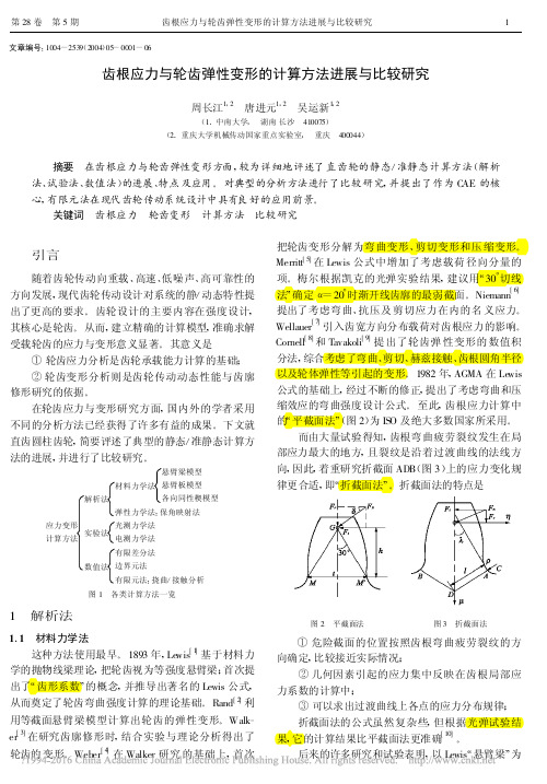
摘要齿啮式快开压力容器具有启闭快、承压能力强、适用压力范围广等优点,被广泛地应用在化工、石油、食品、医疗等工业领域中。
其工作原理是在齿啮式快开装置的圆周方向加工出均布的齿,通过齿间的啮合和错开,达到快速启闭的目的,轴向力由釜体法兰来承担,由齿与齿之间的接触面来传递,是一个典型的接触问题,应力和变形的精确计算相当复杂。
同时,由于容器多为半间歇操作,频繁的开、停工及压力波动使得容器中应力随时间呈周期性变化,这对容器抗疲劳性能提出了较高的要求。
在工作压力下,齿啮式快开压力容器的齿与齿之间的接触面不仅相互挤压而且相对滑动,接触状态随着加载过程而变化,接触面上的应力难以事先确定。
因此,针对国内缺少对整体卡箍齿啮式快开结构研究的问题,以ANSYS软件为主要工作平台,建立整体卡箍齿啮式快开结构的三维模型,根据实际工况对其约束与载荷作了有效处理,针对不同内压作用下的齿啮式快开结构进行有限元分析,得到应力分布规律,确定危险截面,针对危险路径进行线性化处理,依据JB4732-1995《钢制压力容器—分析设计标准》进行强度评定。
针对不同啮合度下的齿啮式快开结构进行了有限元分析,分三种情况,分别是周向、径向、周向与径向组合,得出了允许的啮合错动量。
通过疲劳强度分析,对疲劳寿命进行预测。
现场操作中通常对釜体齿根处的裂纹损伤进行打磨修复,使釜体齿根处呈现不同的圆角尺寸和凹陷尺寸,针对这些结构进行有限元分析,得出应力分布规律,确定允许的打磨量,这对提高齿啮式快开压力容器设计及制造的可靠性、经济性提供了重要的参考依据。
关键词:齿啮式快开结构;有限元;接触分析;疲劳分析;应力线性化处理AbstractTooth-locked quick opening pressure vessel with opening and closing fast, strong bearing capacity, wide applicability, etc. is widely used in petroleum, chemical, food, medical and other industrial fields. The working principle is the circumferential direction is processed in the teeth of the tooth-locked quick closure device. Through the teeth meshing and staggered, the rapid opening and closing is obtained. the axial force is borne by the kettle body flange, by the contact surface between the teeth and teeth to transfer, which is a typical contact problem, the stress and deformation of the accurate calculation is very complicated. At the same time,beacause the semi-batch operation,frequently opening, shuting down the stress and pressure fluctuation change periodically with time in the vessel ,it puts forward higher requirements for fatigue performance.Therefore,aiming at the lack of overall clamp tooth locked quick open structure of the problem,by using ANSYS software as the main working platform, the establishment of the overall card hoop of tooth locked quick open structure of 3D model,according to the actual working condition of the constraint and load for the effective treatment,according to the different pressure under the action of tooth locked quick open structure finite element analysis, stress distribution rules and to determine the dangerous cross-section,the dangerous path of linearization,based on the JB4732-1995 Steel Analysis and DesignStandard of Pressure Vessel,to evaluate the strength.According to the degree of different mesh of tooth locked quick opening structure finite element analysis, divided into three, respectively is week and radial directions, week to radial combination, it is concluded that the allowed engagement wrong momentum. Through fatigue strength analysis, the fatigue life is predicted. Field operation is usually on the kettle body root crack damage of grinding repair and the kettle body root present different fillet size and depression size and finite element analysis for the structure, gets the stress distribution law and to determine allowable grinding amount, which to improve the tooth locked quick opening pressure vessel design and manufacture of the reliability, economy provides an important reference.Key words:Tooth-locked quickopening structure;Finite element;Frictional contact analysis;Fatigue analysis;Stress linearization treatment目录第1章绪论 (1)1.1 研究的工程背景、目的和意义 (1)1.2 快开结构的主要形式及工作原理 (3)1.3 快开结构有限元分析的国内外研究进展 (5)1.4 本文研究内容 (8)第2章不同内压下快开结构的有限元分析 (10)2.1 设计数据及材料性能参数 (10)2.2 快开结构的有限元模拟 (11)2.3 理想啮合状况下的有限元结果分析 (16)2.4 接触面的应力云图 (24)2.5 应力线性化分析与强度评定 (26)2.6 本章小结 (31)第3章不同啮合度下快开结构的有限元分析 (32)3.1 啮合度的定义 (32)3.2 周向错动的有限元分析 (33)3.3 径向错动的有限元分析 (40)3.4 组合错动下的有限元分析 (47)3.5 本章小结 (51)第4章齿啮式快开结构的疲劳分析 (52)4.1 疲劳失效机理 (52)4.2 基于ANSYS的疲劳分析 (55)4.3 理想啮合工况下的疲劳分析 (57)4.4 最危险工况下的疲劳分析 (62)4.5 强度分析与疲劳分析的比较 (64)4.6 本章小结 (65)第5章修复后的啮合齿块的有限元分析 (66)5.1 釜体齿根裂纹产生机理 (66)5.2 带有裂纹的啮合齿块检测及修复 (67)5.3 带有裂纹和修复后的啮合齿块的有限元分析 (69)5.4 本章小结 (79)结论与展望 (80)参考文献 (82)致谢 (85)附录 1.6MPa下快开结构的有限元分析命令流 (86)第1章绪论1.1 研究的工程背景、目的和意义快开式压力容器广泛地应用于石油、化工、建材、食品、纺织、橡胶、航天、医疗、造纸等工业领域需要快速开启和关闭的承压装置中。

含齿根裂纹齿轮副时变啮合刚度改进算法黄金凤;张飞斌;崔玲丽;陈雄飞【摘要】齿轮轮齿局部缺陷故障会通过改变齿轮副的时变啮合刚度进而影响系统振动响应特征.在基于齿廓普遍方程的能量法框架下,结合修正的轮齿拉压刚度,对精确全齿廓齿根裂纹故障齿轮副时变啮合刚度的求解进行系统讨论;针对不同故障参数对应的故障模型,详细地分类讨论,得出了各情况下相应的啮合刚度计算公式.以齿条刀加工的标准直齿轮为对象,研究新模型中齿根裂纹故障对轮齿拉压刚度的影响,为齿轮齿根裂纹故障的诊断机理研究提供基础支撑.【期刊名称】《机械制造与自动化》【年(卷),期】2019(048)002【总页数】5页(P43-47)【关键词】齿轮副;啮合刚度;故障诊断;拉压刚度;普遍方程法【作者】黄金凤;张飞斌;崔玲丽;陈雄飞【作者单位】北京工业大学先进制造技术北京市重点实验室,北京100124;清华大学机械工程系,北京100084;江西农业大学工学院,江西南昌330045;北京工业大学先进制造技术北京市重点实验室,北京100124;江西农业大学工学院,江西南昌330045【正文语种】中文【中图分类】TH132.4120 引言齿轮轮齿故障主要是通过改变齿轮副的时变啮合刚度进而影响系统振动响应特征的。
因此时变啮合刚度的精确求解一直以来都是故障诊断机理研究的关键性基础问题之一。
啮合过程中的单双齿交替啮合及啮合点在啮合线上位置的变化导致即使是正常齿轮的啮合刚度也是时变的。
当齿轮出现故障时,更增加了齿轮时变啮合刚度计算的难度。
因此,研究故障齿轮时变啮合刚度精确高效的计算方法有重要的研究价值。
目前,针对齿轮时变啮合刚度的计算方法有多种。
如实验法[1]、有限元法[2]和能量法[3]。
其中能量法基于材料力学和齿轮几何学,具有精度高、效率高的优点,因此一直是学者们研究的热点方向。
Yang和Lin[4]基于Weber[3]提出的能量法给出了关于齿轮转角变化的啮合综合刚度表达式,文中的啮合刚度由赫兹接触刚度、弯曲刚度和压缩刚度3部分组成。
文章编号:1004-2539(2010)11-0058-04基于非线性动力学模型的齿根裂纹故障分析张青锋 唐力伟 郑海起 杨通强(军械工程学院火炮工程系, 河北石家庄 050003)摘要 基于齿轮系统动力学的理论方法,考虑质量偏心、齿面摩擦及时变刚度等因素的影响,建立了齿根裂纹非线性动力学的故障模型。
通过对模型的数值求解与分析,得出轴的转动振动信号比箱体上的振动信号故障特征更明显。
同时对不同转速、负载的工况下的仿真对比,获得了更有利于提取故障特征的工况,揭示了故障模式下的振动响应的原理和特征,为提取具有更好信噪比的振动信号提供了理论依据。
通过试验验证,证明了结论的正确性,为提高故障诊断的准确性提供了新的途径。
关键词 齿轮系统动力学 故障诊断 仿真分析 故障特征Nonlinear Dynamics Fault Model Analysis on Gear Tooth CrackZhang Qingfeng Tang Li w ei Zheng Haiqi Yang Tongqiang(Department of Guns Engineering,Ordnance Engineeri ng College,Shiji az huang050003,China)Abstract Based on gear system dyna mic s,nonlinear dynamics fault model on gear tooth crack is proposed firstly in consideration of the factors such as friction and eccentric mass.B y the numerical solution and simulation analysis, the c onclusion is that fault feature is more prominence in turning signal than vibration pared different work-ing condition of model including rotate speed and load,the better working condition is found for easy picking up the fault feature.The result revealed the principle and character of vibration response under fault model,and offered aca-demic base for obtaining better signal to faults diagnosis.B y experiment the result proves that this method can break a new path for improving accuracy of faults diagnosis about gear tooth.Key words Gear system dynamics Faults diagnosis Simulation analysis Fault feature0 引言在齿轮箱的故障诊断中,以振动响应信号为基础的齿轮故障诊断方法,相对于其它齿轮故障诊断方法具有测量简便、实时性强等优点,因此振动检测法已经成为目前齿轮箱故障诊断研究领域中应用最广泛的方法。
0引言本文主要对三环传动中变位齿轮的啮合刚度进行分析。
三环主要应用于起重机械、运输机械等以内燃机为动力的工程设备,运用普遍性高。
而变位齿轮系统的一个重要的特性就是啮合刚度,啮合刚度系数也是进行运动学分析的重要参数。
但是齿轮机构在传递运动的过程中,啮合点出现上下位移,因此引起啮合刚度发生变化,所以对啮合刚度分析是有必要的,它直接影响计算和设计精度。
1内啮合变位齿轮动刚度计算方法有限元法的分析主要分为两个方向[1]。
①沿法向载荷方向的位移量,在接触啮合时,分别求出法向载荷与接触啮合齿轮的总变形量,法向载荷与接触啮合齿轮的总变形量比值为啮合刚度。
②转角的变形量,通过求解接触啮合时变形量,再通过变形量求出啮合刚度。
下文将分别对这两个方向进行简单分析。
1.1沿法向载荷方向的位移量计算法齿轮传动系统在啮合力的作用下,在接触啮合面会产生一定的变形,而在接触面的法向载荷F n 为主要载荷,接触啮合齿轮的总变形量为U n ,啮合刚度为:F n U n=K n (1)式中,接触啮合齿轮的总变形量U n 为:U n =U a +U b +U c (2)式中,U a 为接触时剪切变形;U b 为轮齿接触产生的接触变形;U c 为接触时弯曲变形。
三环传动的啮合度为内齿板和外齿轮的啮合刚度总和,而三环传动在工作过程中,属于多齿接触啮合,其啮合刚度简化模型如图1所示。
在图1中,啮合齿轮对1、2、3、4、5的啮合刚度分别为K 1、K 2、K 3、K 4、K 5,五对轮齿啮合时的啮合刚度为并联耦合关系,则多对轮齿的啮合刚度为:K=K 1+K 2+K 3+K 4+K 5(3)1.2转角变形量计算法利用沿法向载荷方向的位移量计算齿轮传动系统的啮合刚度时,由于在接触啮合过程中啮合对的齿轮变形比较复杂,利用沿法向载荷方向的位移量计算齿轮传动系统的啮合刚度相关参数还是比较困难。
运用转角变形量计算法,在主动轮的转动中心添加一个转矩T ,通过转矩T 的作用,计算转角变形量,最后求出齿轮副的啮合刚度。
第53卷第4期表面技术2024年2月SURFACE TECHNOLOGY·1·研究综述喷丸强化对车辆传动齿轮裂纹扩展影响的研究综述李杰1,高紫钰1,王晓燕2*,胡铮3,兰海3,王志勇3(1.北京建筑大学 机电与车辆工程学院,北京 102616;2.北京物资学院 统计与数据科学学院, 北京 101149;3.中国北方车辆研究所 车辆传动重点实验室,北京 100072)摘要:疲劳断裂是重载车辆传动齿轮的主要失效形式之一,齿轮底部疲劳裂纹的扩展将缩短车辆传动系统的服役寿命,严重时会导致车辆发生安全事故。
延缓裂纹扩展的主要方法是在传动齿轮的表面引入一定大小的残余压应力。
喷丸技术是一种冷加工表面强化处理工艺,该技术利用高速弹丸冲击材料表面,使零件表层产生塑性应变的同时,在表面和内部引入残余压应力,从而使裂纹闭合的能力得到强化,达到延缓裂纹扩展的强化效果。
为了更好地揭示喷丸引入的残余压应力对疲劳裂纹扩展的影响,首先综述了传动齿轮表面疲劳裂纹产生的原因以及疲劳裂纹的扩展行为对重载车辆服役的影响。
从强度因子、J积分以及裂纹闭合效应出发,介绍了传动齿轮表面疲劳裂纹扩展的理论以及残余压应力与疲劳裂纹扩展速率之间的关系。
其次概述了目前国内外常用的新型有益于将残余拉应力转化为残余压应力的微粒子喷丸、激光喷丸、超声喷丸方法,并与传统机械喷丸技术相比较,阐述了新型喷丸表面强化技术的优缺点。
此外,从数值模拟和试验结果两方面,论述了喷丸速度、喷丸角度、弹丸直径、弹丸材质和覆盖率5个工艺参数对在传动齿轮表面引入残余压应力的改善影响。
最后对喷丸强化技术在传动齿轮上的多目标参数优化以及多尺度残余压应力与疲劳性能进行了展望,并结合重载车辆的使用需求,强调需要创新设计一种效率高、价格低、适用性广的喷丸技术,以进一步推动喷丸强化在延缓疲劳裂纹扩展方面的持续发展。
关键词:喷丸强化;残余压应力;传动齿轮;疲劳裂纹扩展速率;疲劳寿命;表面强化中图分类号:TG668;TH132.41 文献标志码:A 文章编号:1001-3660(2024)04-0001-19DOI:10.16490/ki.issn.1001-3660.2024.04.001A Review on Effects of Shot Peening on Crack Growth ofVehicle Transmission GearsLI Jie1, GAO Ziyu1, WANG Xiaoyan2*, HU Zheng3, LAN Hai3, WANG Zhiyong3(1. School of Mechanical-electronic and Automobile Engineering, Beijing University of Civil Engineering and Architecture,Beijing 102616, China; 2. School of Statistics and Data Science, Beijing Wuzi University, Beijing 101149, China;3. Key Lab of Vehicular Transmission, China North Vehicle Research Institute, Beijing 100072, China)收稿日期:2023-03-15;修订日期:2023-06-14Received:2023-03-15;Revised:2023-06-14基金项目:国家自然科学基金(51675494);北京建筑大学金字塔人才培养工程(JDJQ20200308);北京建筑大学研究生创新项目(PG2023133)Fund:The National Natural Science Foundation of China (51675494); The Pyramid Talent Training Project of Beijing University of Civil Engineering and Architecture (JDJQ20200308); Postgraduate Innovation Program of Beijing University of Civil Engineering and Architecture (PG2023133)引文格式:李杰, 高紫钰, 王晓燕, 等. 喷丸强化对车辆传动齿轮裂纹扩展影响的研究综述[J]. 表面技术, 2024, 53(4): 1-19.LI Jie, GAO Ziyu, WANG Xiaoyan, et al. A Review on Effects of Shot Peening on Crack Growth of Vehicle Transmission Gears[J]. Surface Technology, 2024, 53(4): 1-19.*通信作者(Corresponding author)·2·表面技术 2024年2月ABSTRACT: Fatigue fracture is one of the main failure modes of the transmission gear of heavy duty vehicles. The service life of the transmission system of vehicles will be shortened due to the expansion of fatigue cracks at the bottom of the teeth, and serious accidents will occur. The generation of residual compressive stress is the main method to delay crack propagation. Shot peening technology is a surface strengthening process of cold working. When the plastic strain is generated on the surface of parts, the residual compressive stress is introduced on the surface and inside, so as to improve the crack closure effect and achieve the strengthening effect of delaying crack propagation. In order to better reveal the influence of the residual compressive stress introduced by shot peening on fatigue crack propagation, the surface of the transmission gear is usually susceptible to a variety of alternating loads, such as external thermal loads and force loads. Compared with static loads, the non-uniformity of the internal structure of the material under alternating loads has a greater influence on the fatigue damage resistance of the material. Fatigue causes tooth breakage. Based on the strength factor, J-integral and crack closure effect, the theory of fatigue crack growth on the transmission gear surface and the relationship between compressive residual stress and fatigue crack growth rate were introduced. The introduction of compressive residual stress could reduce the crack growth rate, improve the fatigue resistance index of fatigue crack, and reduce the stress intensity factor at the crack tip. The new methods of particle shot peening, laser shot peening and ultrasonic shot peening, which were beneficial to the conversion of residual tensile stress to compressive stress, were summarized. The particle shot peening was to use a smaller diameter projectile to impact the surface ofa part at high speed, which could not only introduce compressive residual stress on the surface of the part, but also achievehigher surface finish requirements. Laser shot peening adopted shock wave to carry out high-speed impact, so there would be no additional mechanical damage and surface phase change on the surface of parts. The surface depth after ultrasonic shot peening was much higher than that after traditional shot peening. However, due to its high price or small applicability, it has not been widely used in the surface strengthening of vehicle transmission gears. In the future development, it is necessary to design the shot peening technology with high efficiency, high adaptability, low cost and less energy consumption. At the same time, the relationship between the new shot peening method and the traditional mechanical shot peening technology was described. In addition, based on the numerical simulation and experimental results, the influence of the selection of five process parameters including shot peening speed, shot peening Angle, shot diameter, shot material and coverage rate on the improvement of residual compressive stress introduced on the transmission gear surface was emphatically reported. The compressive residual stress did not increase with the increase of incident velocity and projectile diameter, but tended to be stable when it exceeded a certain limit. Large residual compressive stress could be introduced when the projectile vertically incident impacted the surface of the transmission component. On the other hand, the residual compressive stress increased with the increase of the projectile diameter in the range of 0.2-3.4 mm. Steel shot had a better ability to improve the fatigue strength, ceramic shot after shot peening could achieve better surface smoothness, the final residual compressive stress increased with the increase of shot peening coverage, but the surface coverage was also saturated value. Finally, the future research direction of shot peening technology in transmission gear was prospected, and the technological innovation was further carried out in combination with the use requirements of heavy-duty vehicles, so as to promote the sustainable development of shot peening technology to delay crack propagation. The special simulation of shot peening technology mainly focuses on the selection of single shot peening process parameters of gear, while the analysis of combined parameters is less. However, in practical application, it is necessary to comprehensively consider the influence of coupling effects of various parameters on the gear. Therefore, in future numerical simulation, it is necessary to combine the optimal combination of process parameters to further study the surface integrity of the gear surface after shot peening, such as corrosion resistance, wear resistance and oxidation resistance.KEY WORDS: shot peening; compressive residual stress; transmission gear; fatigue crack growth rate; fatigue life; surface strengthening随着传动齿轮在重型车辆中的广泛应用,关于传动齿轮在交变载荷作用下失效行为的研究越来越多,而传动系统的稳定性是重载车辆使用安全的重要影响因素之一,传动齿轮作为传动系统的薄弱环节,有关它引发的疲劳断裂失效和服役寿命缩短问题的研究越来越深入。