船舶稳性计算表
- 格式:xls
- 大小:19.00 KB
- 文档页数:2
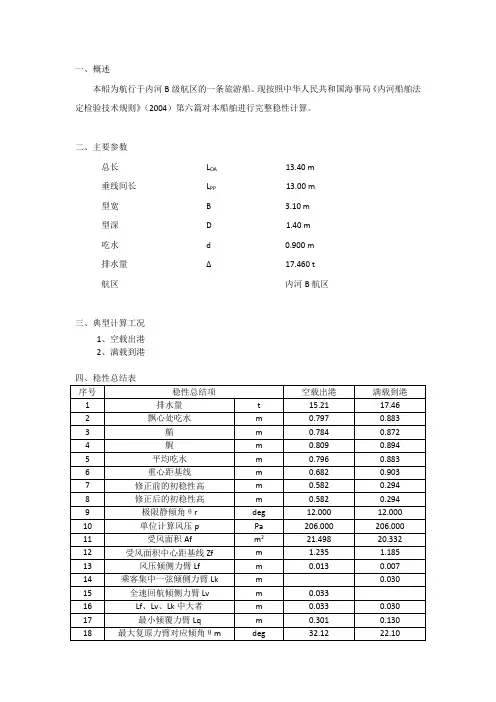
一、概述本船为航行于内河B级航区的一条旅游船。
现按照中华人民共和国海事局《内河船舶法定检验技术规则》(2004)第六篇对本船舶进行完整稳性计算。
二、主要参数总长L OA13.40 m垂线间长L PP13.00 m型宽 B 3.10 m型深 D 1.40 m吃水 d 0.900 m排水量∆17.460 t航区内河B航区三、典型计算工况1、空载出港2、满载到港五、受风面积A及中心高度Z六、旅客集中一弦倾侧力矩L KL K=1∆1−n5lb=0.030 mn lb =1.400<2.5,取nlb=1.400式中:C—系数,C=0.013lbN=0.009<0.013,取C=0.013 n—各活动处所的相当载客人数,按下式计算并取整数n=NSbl=28.000S—全船供乘客活动的总面积,m2,按下式计算:S=bl=20.000 m2b—乘客可移动的横向最大距离,b=2.000 m;l—乘客可移动的横向最大距离,b=2.000 m。
七、全速回航倾侧力矩L VL V=0.045V m2SKG−a2+a3F r d KN−m式中:Fr—船边付氏数,F r=m9.81L;Ls—所核算状态下的船舶水线长,m;d—所核算状态下的船舶型吃水,m;∆—所核算状态下的船舶型排水量,m2;KG—所核算状态下的船舶重心至基线的垂向高,m;Vm—船舶最大航速,m/s;a3—修正系数,按下式计算;a3=25F r−9当a3<0,取a3=0;当a3>1时,取a3=1;a2—修正系数,按下式计算;a2=0.9(4.0−Bs/d)当Bs/d<3.5时,取Bs/d=3.5;当Bs/d>4.0时,取Bs/d=4.0;。
船舶原理公式范文船舶原理是指研究船舶的运动原理以及与之相关的物理学原理的学科。
船舶运动的原理涉及到船舶的稳性、浮力、阻力、推力等多个方面。
下面将介绍一些与船舶原理相关的公式。
1.船舶稳性公式船舶稳性是指船舶在静态和动态情况下保持平衡的能力。
船舶稳性可以通过测量艏楼舱的倾斜角度来评估。
船舶稳性公式中,最常用的是斯奈德稳性公式和S方程。
斯奈德稳性公式:GM=KB*(1-KB/KM)*BM其中,GM是艇身稳定性力矩中心的高度,KB是纵向稳定力矩的位置,KM是质量中心的高度,BM是浸没体积的功能。
通过斯奈德稳定性公式,可以计算船舶的稳定性矩。
S方程:S=KM/(KB+KG)其中,S是形心水平与质心水平之间的距离,KB是纵向稳定力矩的位置,KG是重心的高度。
2.船舶浮力公式船舶浮力是指在液体中受到的向上推力。
根据阿基米德定律,浸没在液体中的物体所受到的浮力等于所排除的液体的重量。
F=ρ*V*g其中,F是浮力,ρ是液体的密度,V是物体所排除的液体的体积,g是重力加速度。
3.船舶阻力公式船舶阻力是指在航行过程中与流体介质之间产生的摩擦力。
船舶阻力公式主要有摩擦阻力公式和波浪阻力公式。
摩擦阻力公式:Rf=0.5*ρ*V^2*S*Cf其中,Rf是摩擦阻力,ρ是介质密度,V是速度,S是湿表面积,Cf 是摩擦阻力系数。
波浪阻力公式:Rw=0.25*ρ*V^2*L^2其中,Rw是波浪阻力,ρ是介质密度,V是速度,L是舰船的长度。
4.船舶推力公式推力公式:T=P*η其中,T是推力,P是功率,η是效率。
以上是一些与船舶原理相关的公式,涉及船舶稳性、浮力、阻力和推力等方面。
这些公式可以帮助研究者理解船舶的运动原理,并为船舶设计和工程提供参考。

图样和技术文件履历 PLAN HISTORY日期 DATE 版本 REV. 标记 MARK 数量Q’TY修改通知单号REVISE NO. 说 明 DESCRIPTION 设绘 DESIGNED 校对 CHECKED 审定 APPROVED 2005-12-23A 完工文件 黄小勇 李从波杨葆和OT1100-1 FINAL DESIGN图号 DWG.NO DL594-050-006JS标记 数量 修改单号 签字 日期 110,000吨级载重量原油船 110,000DWT Crude Oil Tanker 代码 CODE版本REV .A 重量kg MASS 比例 SCALE 设绘DESIGNED校对CHECKED共 63 页 TOTAL SHEETS 第 1 页 SHEET 审核REVIEWED完工破舱稳性计算 FINAL DAMAGE STABILITY CALCULATION 标检STANDARDIZED审定APPROVED 天鹅洲 TIAN E ZHOU 大连造船重工有限责任公司 船 舶 设 计 研 究 所 DALIAN SHIPYARD CO . , LTDSHIP DESIGN & RESEARCH INSTITUTECONTENTS1.PRINCIPAL PARTICULAR (3)1.1.G ENERAL (3)1.2.P RINCIPAL D IMENSIONS (3)2.EXPLANATION TO THE CALCULATION (3)2.1.ICLL1966/1988 (3)2.2.MARPOL 73/78 (6)3.DAMAGE CASE (8)4.RESTRICT (12)4.1.D OWN-F LOODING P OINTS (12)4.2.W EATHER-T IGHT P OINTS (12)5.RESULTS OF THE DAMAGE STABILITY CALCULATION (13)1. Principal Particular1.1. GeneralHull No.: OT1100-1CCS Con. No.: SP046069Owner: Nanjing Changjiang Oil Transportation Co.Builder: Dalian Shipyard Co., Ltd.Designer: MARIC82Navigation Area: Unrestricted Ocean-goingClass: CSA, Oil Tanker, Double Hull, F.P.≤60°C, CCSS, ESP,Ice Class B, In Water Survey, Single Point Mooring,Emergency Towing Arrangements, Loading ComputerS.I.D.CSM, AUT-0, SCM, IGS, CMSDimensions1.2. PrincipalLength over all: about 244.500 mLength, registered: 234.980 mLength between perpendiculars: 233.000 mBreadth (Moulded): 42.000 mDepth (Moulded): 21.900 mCamber: 0.780 mDesign Draught (Moulded): 12.000 mScantling (Maximum Summer) Draught (Moulded): 15.500 mSummer Freeboard (from Top of Freeboard Deck): 6.416 mDisplacement (Design/Scantling Draught): 97771/130201 tLightship Weight (assumed): 19930.4 tDeadweight (Design/Scantling Draught): about 77840.6 t/110270.6 tBlock coefficient (Design/Scantling Draught): 0.8123/0.8374Total Overall Area of Bilge Keels : 53.2m2 (Fr.118~ Fr.163)(Fr.168~Fr.208)Capacity:Cargo Oil Tanks (100%Full, including SLOP T.): 126656.7 m3Heavy Fuel Oil Tanks (100%Full, including H.F.O.Overflow T.) 3420.4 m3Diesel Oil Tanks (100%Full) 230.8 m3Lubrication Oil Tanks (100%Full) 169.9 m3Ballast Water Tanks (100%Full) 39042.1 m3Fresh Water Tanks (100%Full) 519.6 m32. Explanation to the CalculationThe proof of the damage stability is effected according to the criteria of ICLL66/1988protocol and “MARPOL 73/78” Consolidated Edition 20022.1. ICLL1966/19882.1.1 Type of ship and intended useThis ship’s purpose of freeboard computation is type A (See FREEBOARD CALCULATION, Drawing No. DL594-101-005JS), she is designed to carry liquid cargoes in bulk; she has a high integrity of exposed deck with only small access openings to cargo compartments, closed by watertight gasketed covers of steel or equivalent material; and has low permeability of load cargo compartments.The type A ship when loaded in accordance with the requirements of paragraph 2.1.2 shall be able to withstand the flooding of any compartment or compartments, with an assumed permeability of 0.95, consequent upon the damage assumptions specified in paragraph 2.1.2, and shall remain afloat in a satisfactory condition of equilibrium as specified in paragraph 2.1.3. In such a ship the machinery space shall be treated as a floodable compartment, but with a permeability 0.85.2.1.2 Initial Conditions of LoadingThe initial condition of loading before flooding shall be determined as follows:a) The ship is loaded to its summer load waterline on an imaginary even keel.b) When calculating the vertical center of gravity, the following principles apply:(i) Homogeneous cargo is carried.(ii) All cargo compartments, except those referred to under (iii) of this sub-paragraph, but including compartments intended to be partially filled, shall be consideredfully loaded except that in the case of fluid cargoes each compartment shall betreated as 98 percent full.(iii) If the ship is intended to operate at its summer load waterline with empty compartments, such compartments shall be considered empty provided the heightof the center of gravity so calculated is not less than as calculated under (ii) of thissub-paragraph.(iv) Fifty percent of the individual total capacity of all tanks and spaces fitted to contain consumable liquids and stores is allowed for. It shall be assumed that foreach type of liquid, at least on transverse pair or a single center line tank hasmaximum free surfaces is the greatest; in each tank the center of gravity of thecontents shall be taken at the center of volume of the tank. The remaining tanksshall be assumed either completely empty or completely filled, and thedistribution of consumable liquids between these tanks shall be effected so as toobtain the greatest possible height above the keel for the center of gravity.(v) At an angle of heel of not more than 5 degree in each compartment containing liquids, as prescribed in (ii) of this sub-paragraph except that in the case ofcompartments containing consumable fluids, as prescribed in (iv) of thissub-paragraph of this paragraph, the maximum free surface effect shall be takeninto account. Alternatively, the actual free surface effects may be used, providedthe methods of calculation are acceptable to the Administration.(vi) Weight shall be calculated on the basis of the following values for specific gravities:Salt Water 1.025Fresh Water 1.000Oil Fuel 0.950Diesel Oil 0.900Lubricating Oil 0.900Calculation of this initial loading condition “Load Line”INIT LOADLINET, 15.5TRIM, 0KG, 12.58GMR 1.25 (GM-reduction)OK2.1.3 Damage AssumptionsThe following principles regarding the character of the assumed damage apply:a) The vertical extent of damage in all case is assumed to be from base line upwardswithout limit.b) The transverse extent of damage is equal to B/5=8.4m (or 11.5m, whichever is thelesser), measured inboard from the side of the ship perpendicularly to the centerline at the level of the summer load waterline.c) If damage of a lesser extent than specified in sub-paragraphs a) and b) of thisparagraph results in a more severe condition, such lesser extent shall be assumed.d) The flooding shall be confined to a single compartment between adjacent transversebulkheads provided the inner longitudinal boundary of the compartment is not in aposition within the transverse extent of assumed damage. Transverse boundarybulkheads of wing tanks, which do not extend over the full breadth of the ship shallbe assumed not to be damaged, provided they extend beyond the transverse extentof assumed damage prescribed in sub-paragraph b) of this paragraph. If in atransverse bulkhead there are steps or recesses of not more than 3.00 meters inlength located within the transverse extent of assumed damage as defined insub-paragraph b) of this paragraph, such transverse bulkhead may be consideredintact and the adjacent compartment may be floodable singly. If, however, withinthe transverse extent of assumed damage there is a step or recess of more than 3.00meters in length in a transverse bulkhead, the two compartments adjacent to thisbulkhead shall be considered as flooded. The step formed by the after peakbulkhead and the after peak tank top shall not be regarded as a step for the purposeof this Regulation.e) Where the flooding of any two adjacent fore and aft compartments is envisagedmain transverse watertight bulkheads shall be spaced at least 1/3L2/3=12.69m (or14.5m, whichever is the lesser), in order to be considered effective. Wheretransverse bulkhead are spaced at a lesser distance. One or more of these bulkheadsshall be assumed as non-existent in order to achieve the minimum spacing betweenbulkheads.2.1.4 Condition of Equilibriuma) The final waterline after flooding, taking into account sinkage, heel, and trim, isbelow the lower edge of any opening through which progressive flooding may takeplace. Such openings shall in include air pipes, ventilators and openings which areclosed by means of weathertight doors or hatch covers, and may exclude thoseopenings closed by means of manhole covers and flush scuttles, cargo hatch covers,remotely operated sliding watertight doors, and side scuttles of the non-openingtype.(PROGR.LL)b) If pipes, ducts or tunnels are situated within the assumed extent of damagepenetration as defined in paragraph 2.1.3 b), arrangements are to be made so thatprogressive flooding cannot thereby extend to compartments other than thoseassumed to be floodable in the calculation for each case of damage.c) The angle of heel due to unsymmetrical flooding does not exceed 15 degrees. If nopart of the deck is immersed, an angle of heel of up to 17 degrees may beaccepted.(MAXHEEL.LL)d) The metacentric height in the flooded condition is positive.(MINGM.LL)e) When any part of the deck outside the compartment assumed flooded in particularcase of damage is immersed, or in any case where the margin of stability in theflooded condition may be considered doubtful, the residual stability is to beinvestigated. It may be regarded as sufficient if the righting lever curve hasminimum range of 20 degrees beyond the position of equilibrium(RANGE.LL)with a maximum righting lever of at least 0.1 meter within thisrange(MAXGZ.LL). The area under the righting lever curve within this range shallbe not less than 0.0175 meter-radians(MINAREA.LL). The administration shallThe following provisions regarding the extent and the character of the assumeddamage shall apply:a) Side Damage(i) Longitudinal extent 1/3L2/3=12.96m (or 14.5 m, whichever is less)(ii) Transverse extent B/5=8.4m (or 11.5 m, whichever is less) (inboard from the ship’s side at right angles to the center-line at the level of the summer load line)(iii) Vertical extent from the moulded line of the bottom shell plating atcenter-line, upwards without limitb) Bottom DamageFor 0.3L (#203+484) from the F.P. Any other part of the ship(i) Longitudinal extent 1/3L2/3=12.96 meters 5 meters(or 14.5m, whichever is less) (or 1/3L2/3, whichever is less) (ii) Transverse extent B/6= 7 meters 5 meters(or 10m, whichever is less) (or B/6, whichever is less) (iii) Vertical extent B/15=2.8 meters(or 6m, whichever is less measured from the moulded line of thebottom shell plating at centerline)c) Bottom Raking Damage(i) Longitudinal extent 0.6L=140.988m measured from F.P. (from #117+510)(ii) Transverse extent B/3=16 meters anywhere in the bottom(iii) Vertical extent breach of the outer hulld) If any damage of a lesser extent than the maximum extent of damage specified in a)and b) of this paragraph would result in a more severe condition, such damage shallbe considered.e) Where the damage involving transverse bulkheads is envisaged as specified insubparagraph 2.2.1, transverse watertight bulkheads shall be spaced at least at adistance equal to the longitudinal extent of assumed damage specified in a) of thisparagraph in order to be considered effective. Where transverse bulkheads are spacedat a lesser distance, one or more of these bulkheads within such extent of damageshall be assumed as non-existent for the purpose of determining floodedcompartments.f) If pipes, ducts or tunnels are situated within the assumed extent of damage,arrangements shall be made so that progressive flooding cannot thereby extend tocompartments other than those assumed to be floodable for each of dagame.2.2.4 Damage Stability CriteriaThis ship shall be regarded as complying with the damage stability criteria if thefollowing requirements are met:a) The final waterline, taking into account sinkage, heel and trim, shall be below thelower edge of any opening through which progressive flooding may take place. Suchopenings shall include air-pipes and those which are closed by means of watertightdoors or hatch covers and may exclude those openings closed by means of watertightmanhole covers and flush scuttles, small watertight cargo tank hatch covers whichmaintain the high integrity of the deck, remotely operated watertight sliding doors,and sidescuttles of the non-opening type.(PROGR.M)b) In the final stage of flooding, the angle of heel due to unsymmetrical flooding shallnot exceed 25 degrees, provided that this angle may be increased up to 30 degrees ifno deck edge immersion occurs.(MAXHEEL.M)c) The stability in the final stage of flooding shall be investigated and may be regardedas sufficient I the righting lever curve has at least a range of 20 degrees beyond theposition of equilibrium(RANGE.M) in association with a maximum residual rightinglever of at least 0.1m within the 20 degrees range(MAXGZ.M); the area under thecurve within this range shall not be less than 0.0175 meter radians(MINAREA.M).5. RESULT OF DAMAGE STABILITY CALCULATIONABBREVIATIONS USED IN THE OUTPUT LISTSCASE initial cond/damage case T draught, moulded m TR trim m HEEL heeling angle degree RANGE range of righting lever degree MAXGZ maximum of GZ-curve m MAXKG maximum KG m FAUN fl. angle of unprotected openings degree FAWE fl. angle of weathertight openings degree CASE initial cond/damage case RCR relevant criteria SIDE side of ship SB/PS REQ required value ATTV attained value UNIT unit STAT status of stability crit.5.1 DAMAGE STABILITY FOR ICLL TYPERESULTS---------------------------------------------------------------------- CASE T TR HEEL RANGE MAXGZ MAXKG FAUN FAWE m m degree degree m m degree degree ---------------------------------------------------------------------- IL/LL01 15.628 0.865 0.0 79.9 2.43 17.772 40.1 20.3 IL/LL02 17.128 8.793 0.0 75.1 1.70 16.806 - 8.3 IL/LL03 16.546 3.874 8.3 68.5 1.33 14.061 31.3 14.7 IL/LL04 16.458 3.360 8.4 69.9 1.42 14.494 32.5 15.9 IL/LL05 16.424 1.307 8.2 69.8 1.43 15.124 35.6 16.6 IL/LL06 16.436 -0.495 8.3 68.9 1.38 15.039 38.3 16.9 IL/LL07 16.463 -2.354 8.5 67.6 1.29 14.876 41.1 15.1 IL/LL08 16.506 -4.421 8.9 65.8 1.17 14.307 44.2 13.1 IL/LL09 16.453 -5.648 7.3 67.6 1.30 14.760 46.7 12.2 IL/LL10 15.883 -2.360 0.0 79.2 2.30 17.823 44.6 17.5 ----------------------------------------------------------------------STABILITY CRITERIA---------------------------------------------------------------------- CASE RCR SIDE REQ ATTV UNIT STAT ---------------------------------------------------------------------- IL/LL01 PROGR.LL SB 0.0000 6.5998 m OK IL/LL01 MAXHEEL.LL SB 17.0000 0.0000 deg OK IL/LL01 MINGM.LL SB 0.0000 5.2083 m OK IL/LL01 MAXGZ.LL SB 0.1000 1.9180 m OK IL/LL01 MINAREA.LL SB 0.0175 0.3306 mrad OK IL/LL01 RANGE.LL SB 20.0000 40.1243 deg OK IL/LL02 PROGR.LL SB 0.0000 1.4605 m OK IL/LL02 MAXHEEL.LL SB 17.0000 0.0290 deg OK IL/LL02 MINGM.LL SB 0.0000 4.7575 m OK IL/LL02 MAXGZ.LL SB 0.1000 1.4645 m OK IL/LL02 MINAREA.LL SB 0.0175 0.2776 mrad OK IL/LL02 RANGE.LL SB 20.0000 75.0842 deg OK IL/LL03 PROGR.LL SB 0.0000 2.3562 m OK IL/LL03 MAXHEEL.LL SB 17.0000 8.3447 deg OK IL/LL03 MINGM.LL SB 0.0000 5.6932 m OK IL/LL03 MAXGZ.LL SB 0.1000 1.2612 m OK IL/LL03 MINAREA.LL SB 0.0175 0.2758 mrad OK IL/LL03 RANGE.LL SB 20.0000 22.9367 deg OK IL/LL04 PROGR.LL SB 0.0000 2.7109 m OK IL/LL04 MAXHEEL.LL SB 17.0000 8.4008 deg OK IL/LL04 MINGM.LL SB 0.0000 5.7522 m OK IL/LL04 MAXGZ.LL SB 0.1000 1.3361 m OK IL/LL04 MINAREA.LL SB 0.0175 0.2897 mrad OK IL/LL04 RANGE.LL SB 20.0000 24.1371 deg OK IL/LL05 PROGR.LL SB 0.0000 2.9611 m OK IL/LL05 MAXHEEL.LL SB 17.0000 8.1788 deg OK IL/LL05 MINGM.LL SB 0.0000 5.7075 m OK IL/LL05 MAXGZ.LL SB 0.1000 1.3602 m OK IL/LL05 MINAREA.LL SB 0.0175 0.2985 mrad OK IL/LL05 RANGE.LL SB 20.0000 27.3969 deg OK IL/LL06 PROGR.LL SB 0.0000 3.1765 m OK IL/LL06 MAXHEEL.LL SB 17.0000 8.2596 deg OK IL/LL06 MINGM.LL SB 0.0000 5.6442 m OK---------------------------------------------------------------------- CASE RCR SIDE REQ ATTV UNIT STAT ---------------------------------------------------------------------- IL/LL07 PROGR.LL SB 0.0000 2.4445 m OK IL/LL07 MAXHEEL.LL SB 17.0000 8.5016 deg OK IL/LL07 MINGM.LL SB 0.0000 5.5918 m OK IL/LL07 MAXGZ.LL SB 0.1000 1.2463 m OK IL/LL07 MINAREA.LL SB 0.0175 0.2799 mrad OK IL/LL07 RANGE.LL SB 20.0000 32.6124 deg OK IL/LL08 PROGR.LL SB 0.0000 1.5488 m OK IL/LL08 MAXHEEL.LL SB 17.0000 8.9487 deg OK IL/LL08 MINGM.LL SB 0.0000 5.5140 m OK IL/LL08 MAXGZ.LL SB 0.1000 1.1355 m OK IL/LL08 MINAREA.LL SB 0.0175 0.2569 mrad OK IL/LL08 RANGE.LL SB 20.0000 35.2638 deg OK IL/LL09 PROGR.LL SB 0.0000 1.8294 m OK IL/LL09 MAXHEEL.LL SB 17.0000 7.2563 deg OK IL/LL09 MINGM.LL SB 0.0000 5.3629 m OK IL/LL09 MAXGZ.LL SB 0.1000 1.2409 m OK IL/LL09 MINAREA.LL SB 0.0175 0.2693 mrad OK IL/LL09 RANGE.LL SB 20.0000 39.4721 deg OK IL/LL10 PROGR.LL SB 0.0000 6.0562 m OK IL/LL10 MAXHEEL.LL SB 17.0000 0.0000 deg OK IL/LL10 MINGM.LL SB 0.0000 5.3163 m OK IL/LL10 MAXGZ.LL SB 0.1000 1.8956 m OK IL/LL10 MINAREA.LL SB 0.0175 0.3337 mrad OK IL/LL10 RANGE.LL SB 20.0000 44.6467 deg OK ----------------------------------------------------------------------5.2 DAMAGE STABILITY FOR MARPOLINITIAL CONDITION : I01RESULTS---------------------------------------------------------------------- CASE T TR HEEL RANGE MAXGZ MAXKG FAUN FAWE m m degree degree m m degree degree ---------------------------------------------------------------------- I01/SD01 16.726 7.407 0.1 75.4 1.72 16.495 - 10.8 I01/SD02 17.129 9.334 3.9 69.1 1.24 14.925 - 9.7 I01/SD03 15.569 0.712 2.4 76.5 1.95 16.291 37.9 19.6 I01/SD04 15.725 1.210 5.1 73.6 1.60 15.533 36.1 19.0 I01/SD05 15.606 0.490 3.8 74.6 1.66 15.736 38.5 19.3 I01/SD06 15.605 0.257 3.8 74.2 1.61 15.671 40.1 19.0 I01/SD07 15.607 0.025 3.8 73.6 1.54 15.558 41.9 18.1 I01/SD08 15.661 -0.484 3.9 72.7 1.48 15.441 43.8 17.8 I01/SD09 16.057 -2.964 2.8 72.5 1.63 15.941 45.9 15.2 I01/BB01 16.650 -4.496 15.0 64.4 0.86 13.483 41.9 18.2 I01/BB02 18.507 -6.851 0.3 79.7 1.49 16.426 42.1 14.4 I01/AD01 17.158 9.465 3.2 71.2 1.47 15.675 - 9.9 I01/AD02 15.783 1.536 4.7 74.8 2.05 16.273 38.9 19.4 I01/AD03 15.956 1.840 7.6 72.4 1.80 15.695 37.4 19.0 I01/AD04 15.894 0.611 6.7 73.0 1.86 15.837 39.5 19.2 I01/AD05 15.901 -0.243 6.8 72.7 1.83 15.790 40.6 18.9 I01/AD06 15.907 -1.103 6.9 72.4 1.80 15.740 41.8 18.0 I01/AD07 15.940 -2.068 6.7 71.9 1.74 15.679 43.2 17.9 I01/AD08 16.159 -3.585 3.6 72.7 1.76 16.066 45.4 15.3 ---------------------------------------------------------------------- STABILITY CRITERIA---------------------------------------------------------------------- CASE RCR SIDE REQ ATTV UNIT STAT ---------------------------------------------------------------------- I01/SD01 PROGR.M SB 0.0000 3.6047 m OK I01/SD01 MAXHEEL.M SB 30.0000 0.0622 deg OK I01/SD01 RANGE.M SB 20.0000 75.4464 deg OK I01/SD01 MAXGZ.M SB 0.1000 1.4167 m OK I01/SD01 MINAREA.M SB 0.0175 0.2531 mrad OK I01/SD02 PROGR.M SB 0.0000 2.2401 m OK I01/SD02 MAXHEEL.M SB 30.0000 3.9033 deg OK I01/SD02 RANGE.M SB 20.0000 69.0815 deg OK I01/SD02 MAXGZ.M SB 0.1000 1.1139 m OK I01/SD02 MINAREA.M SB 0.0175 0.2182 mrad OK I01/SD03 PROGR.M SB 0.0000 6.2186 m OK I01/SD03 MAXHEEL.M SB 30.0000 2.3821 deg OK I01/SD03 RANGE.M SB 20.0000 35.5630 deg OK I01/SD03 MAXGZ.M SB 0.1000 1.6231 m OK I01/SD03 MINAREA.M SB 0.0175 0.2844 mrad OK I01/SD04 PROGR.M SB 0.0000 5.1755 m OK I01/SD04 MAXHEEL.M SB 30.0000 5.1316 deg OK I01/SD04 RANGE.M SB 20.0000 30.9867 deg OK I01/SD04 MAXGZ.M SB 0.1000 1.4238 m OK I01/SD04 MINAREA.M SB 0.0175 0.2729 mrad OK---------------------------------------------------------------------- I01/SD05 MAXGZ.M SB 0.1000 1.4675 m OK I01/SD05 MINAREA.M SB 0.0175 0.2707 mrad OK I01/SD06 PROGR.M SB 0.0000 5.7500 m OK I01/SD06 MAXHEEL.M SB 30.0000 3.7807 deg OK I01/SD06 RANGE.M SB 20.0000 36.3582 deg OK I01/SD06 MAXGZ.M SB 0.1000 1.4409 m OK I01/SD06 MINAREA.M SB 0.0175 0.2666 mrad OK I01/SD07 PROGR.M SB 0.0000 5.8232 m OK I01/SD07 MAXHEEL.M SB 30.0000 3.7786 deg OK I01/SD07 RANGE.M SB 20.0000 38.1306 deg OK I01/SD07 MAXGZ.M SB 0.1000 1.3902 m OK I01/SD07 MINAREA.M SB 0.0175 0.2578 mrad OK I01/SD08 PROGR.M SB 0.0000 5.6213 m OK I01/SD08 MAXHEEL.M SB 30.0000 3.9415 deg OK I01/SD08 RANGE.M SB 20.0000 39.9153 deg OK I01/SD08 MAXGZ.M SB 0.1000 1.3400 m OK I01/SD08 MINAREA.M SB 0.0175 0.2522 mrad OK I01/SD09 PROGR.M SB 0.0000 4.7735 m OK I01/SD09 MAXHEEL.M SB 30.0000 2.7706 deg OK I01/SD09 RANGE.M SB 20.0000 43.1754 deg OK I01/SD09 MAXGZ.M SB 0.1000 1.4878 m OK I01/SD09 MINAREA.M SB 0.0175 0.2809 mrad OK I01/BB01 PROGR.M SB 0.0000 1.1593 m OK I01/BB01 MAXHEEL.M SB 30.0000 14.9772 deg OK I01/BB01 RANGE.M SB 20.0000 26.9608 deg OK I01/BB01 MAXGZ.M SB 0.1000 0.8032 m OK I01/BB01 MINAREA.M SB 0.0175 0.1846 mrad OK I01/BB02 PROGR.M SB 0.0000 1.1797 m OK I01/BB02 MAXHEEL.M SB 30.0000 0.3366 deg OK I01/BB02 RANGE.M SB 20.0000 41.7704 deg OK I01/BB02 MAXGZ.M SB 0.1000 1.3516 m OK I01/BB02 MINAREA.M SB 0.0175 0.2708 mrad OK I01/AD01 PROGR.M SB 0.0000 2.4491 m OK I01/AD01 MAXHEEL.M SB 30.0000 3.1838 deg OK I01/AD01 RANGE.M SB 20.0000 71.1723 deg OK I01/AD01 MAXGZ.M SB 0.1000 1.3319 m OK I01/AD01 MINAREA.M SB 0.0175 0.2651 mrad OK I01/AD02 PROGR.M SB 0.0000 5.0713 m OK I01/AD02 MAXHEEL.M SB 30.0000 4.7022 deg OK I01/AD02 RANGE.M SB 20.0000 34.1705 deg OK I01/AD02 MAXGZ.M SB 0.1000 1.7514 m OK I01/AD02 MINAREA.M SB 0.0175 0.3265 mrad OK I01/AD03 PROGR.M SB 0.0000 4.0023 m OK I01/AD03 MAXHEEL.M SB 30.0000 7.5870 deg OK I01/AD03 RANGE.M SB 20.0000 29.8682 deg OK I01/AD03 MAXGZ.M SB 0.1000 1.5989 m OK I01/AD03 MINAREA.M SB 0.0175 0.3230 mrad OK I01/AD04 PROGR.M SB 0.0000 4.2642 m OK I01/AD04 MAXHEEL.M SB 30.0000 6.7359 deg OK I01/AD04 RANGE.M SB 20.0000 32.7438 deg OK I01/AD04 MAXGZ.M SB 0.1000 1.6402 m OK I01/AD04 MINAREA.M SB 0.0175 0.3240 mrad OK I01/AD05 PROGR.M SB 0.0000 4.3450 m OK I01/AD05 MAXHEEL.M SB 30.0000 6.8126 deg OK I01/AD05 RANGE.M SB 20.0000 33.8385 deg OK---------------------------------------------------------------------- I01/AD06 MAXHEEL.M SB 30.0000 6.8793 deg OK I01/AD06 RANGE.M SB 20.0000 34.9723 deg OK I01/AD06 MAXGZ.M SB 0.1000 1.6020 m OK I01/AD06 MINAREA.M SB 0.0175 0.3187 mrad OK I01/AD07 PROGR.M SB 0.0000 4.0134 m OK I01/AD07 MAXHEEL.M SB 30.0000 6.6923 deg OK I01/AD07 RANGE.M SB 20.0000 36.4987 deg OK I01/AD07 MAXGZ.M SB 0.1000 1.5638 m OK I01/AD07 MINAREA.M SB 0.0175 0.3110 mrad OK I01/AD08 PROGR.M SB 0.0000 4.1796 m OK I01/AD08 MAXHEEL.M SB 30.0000 3.5919 deg OK I01/AD08 RANGE.M SB 20.0000 41.7904 deg OK I01/AD08 MAXGZ.M SB 0.1000 1.5932 m OK I01/AD08 MINAREA.M SB 0.0175 0.3031 mrad OK ----------------------------------------------------------------------INITIAL CONDITION : I02RESULTS---------------------------------------------------------------------- CASE T TR HEEL RANGE MAXGZ MAXKG FAUN FAWE m m degree degree m m degree degree ---------------------------------------------------------------------- I02/SD01 17.069 8.911 0.1 75.6 1.67 16.334 - 8.4 I02/SD02 17.349 10.232 3.0 71.1 1.28 14.849 - 8.6 I02/SD03 15.430 0.102 0.9 79.1 2.16 16.484 38.9 20.1 I02/SD04 15.585 0.607 3.5 76.5 1.82 15.681 37.1 19.4 I02/SD05 15.604 0.404 3.4 76.6 1.79 15.699 38.6 19.4 I02/SD06 15.604 0.186 3.4 76.6 1.74 15.630 40.2 18.9 I02/SD07 15.607 -0.035 3.4 76.6 1.67 15.511 42.0 18.0 I02/SD08 15.663 -0.539 3.6 75.9 1.60 15.397 44.0 17.7 I02/SD09 16.062 -3.053 2.5 75.4 1.75 15.902 46.1 15.1 I02/BB01 16.694 -4.518 14.2 65.8 1.00 13.460 42.0 18.3 I02/BB02 18.508 -6.933 0.2 79.8 1.61 16.424 42.2 14.1 I02/AD01 16.809 7.369 2.1 76.6 1.80 16.106 - 12.4 I02/AD02 15.697 1.073 3.6 76.4 2.25 16.375 39.8 20.0 I02/AD03 15.884 1.387 6.5 73.5 2.01 15.784 38.4 19.4 I02/AD04 15.907 0.532 6.3 73.7 1.99 15.784 39.6 19.3 I02/AD05 15.915 -0.317 6.4 73.6 1.96 15.735 40.8 18.8 I02/AD06 15.922 -1.174 6.4 73.6 1.92 15.684 42.0 18.0 I02/AD07 15.953 -2.136 6.3 73.7 1.87 15.620 43.3 17.8 I02/AD08 16.165 -3.671 3.3 75.5 1.88 16.025 45.5 15.2 ---------------------------------------------------------------------- STABILITY CRITERIA---------------------------------------------------------------------- CASE RCR SIDE REQ ATTV UNIT STAT ---------------------------------------------------------------------- I02/SD01 PROGR.M SB 0.0000 2.7764 m OK I02/SD01 MAXHEEL.M SB 30.0000 0.0632 deg OK I02/SD01 RANGE.M SB 20.0000 75.5976 deg OK I02/SD01 MAXGZ.M SB 0.1000 1.4088 m OK I02/SD01 MINAREA.M SB 0.0175 0.2592 mrad OK I02/SD02 PROGR.M SB 0.0000 2.1374 m OK I02/SD02 MAXHEEL.M SB 30.0000 3.0243 deg OK I02/SD02 RANGE.M SB 20.0000 71.0840 deg OK I02/SD02 MAXGZ.M SB 0.1000 1.1374 m OK I02/SD02 MINAREA.M SB 0.0175 0.2213 mrad OK I02/SD03 PROGR.M SB 0.0000 6.9188 m OK I02/SD03 MAXHEEL.M SB 30.0000 0.8790 deg OK I02/SD03 RANGE.M SB 20.0000 38.0389 deg OK I02/SD03 MAXGZ.M SB 0.1000 1.6909 m OK I02/SD03 MINAREA.M SB 0.0175 0.2837 mrad OK I02/SD04 PROGR.M SB 0.0000 5.9294 m OK I02/SD04 MAXHEEL.M SB 30.0000 3.4957 deg OK I02/SD04 RANGE.M SB 20.0000 33.5669 deg OK I02/SD04 MAXGZ.M SB 0.1000 1.5385 m OK I02/SD04 MINAREA.M SB 0.0175 0.2786 mrad OK I02/SD05 PROGR.M SB 0.0000 5.8372 m OK I02/SD05 MAXHEEL.M SB 30.0000 3.4061 deg OK I02/SD05 RANGE.M SB 20.0000 35.2194 deg OK---------------------------------------------------------------------- CASE RCR SIDE REQ ATTV UNIT STAT ---------------------------------------------------------------------- I02/SD06 MAXHEEL.M SB 30.0000 3.4074 deg OK I02/SD06 RANGE.M SB 20.0000 36.8415 deg OK I02/SD06 MAXGZ.M SB 0.1000 1.5195 m OK I02/SD06 MINAREA.M SB 0.0175 0.2792 mrad OK I02/SD07 PROGR.M SB 0.0000 5.9505 m OK I02/SD07 MAXHEEL.M SB 30.0000 3.4133 deg OK I02/SD07 RANGE.M SB 20.0000 38.6122 deg OK I02/SD07 MAXGZ.M SB 0.1000 1.4683 m OK I02/SD07 MINAREA.M SB 0.0175 0.2704 mrad OK I02/SD08 PROGR.M SB 0.0000 5.7355 m OK I02/SD08 MAXHEEL.M SB 30.0000 3.5863 deg OK I02/SD08 RANGE.M SB 20.0000 40.3902 deg OK I02/SD08 MAXGZ.M SB 0.1000 1.4181 m OK I02/SD08 MINAREA.M SB 0.0175 0.2651 mrad OK I02/SD09 PROGR.M SB 0.0000 4.8327 m OK I02/SD09 MAXHEEL.M SB 30.0000 2.5055 deg OK I02/SD09 RANGE.M SB 20.0000 43.5737 deg OK I02/SD09 MAXGZ.M SB 0.1000 1.5638 m OK I02/SD09 MINAREA.M SB 0.0175 0.2943 mrad OK I02/BB01 PROGR.M SB 0.0000 1.4314 m OK I02/BB01 MAXHEEL.M SB 30.0000 14.2365 deg OK I02/BB01 RANGE.M SB 20.0000 27.8222 deg OK I02/BB01 MAXGZ.M SB 0.1000 0.9087 m OK I02/BB01 MINAREA.M SB 0.0175 0.2058 mrad OK I02/BB02 PROGR.M SB 0.0000 1.1376 m OK I02/BB02 MAXHEEL.M SB 30.0000 0.2173 deg OK I02/BB02 RANGE.M SB 20.0000 42.0328 deg OK I02/BB02 MAXGZ.M SB 0.1000 1.4289 m OK I02/BB02 MINAREA.M SB 0.0175 0.2855 mrad OK I02/AD01 PROGR.M SB 0.0000 3.6164 m OK I02/AD01 MAXHEEL.M SB 30.0000 2.1134 deg OK I02/AD01 RANGE.M SB 20.0000 76.5889 deg OK I02/AD01 MAXGZ.M SB 0.1000 1.5589 m OK I02/AD01 MINAREA.M SB 0.0175 0.2981 mrad OK I02/AD02 PROGR.M SB 0.0000 5.6340 m OK I02/AD02 MAXHEEL.M SB 30.0000 3.5865 deg OK I02/AD02 RANGE.M SB 20.0000 36.2347 deg OK I02/AD02 MAXGZ.M SB 0.1000 1.8507 m OK I02/AD02 MINAREA.M SB 0.0175 0.3327 mrad OK I02/AD03 PROGR.M SB 0.0000 4.5032 m OK I02/AD03 MAXHEEL.M SB 30.0000 6.4999 deg OK I02/AD03 RANGE.M SB 20.0000 31.8955 deg OK I02/AD03 MAXGZ.M SB 0.1000 1.7291 m OK I02/AD03 MINAREA.M SB 0.0175 0.3368 mrad OK I02/AD04 PROGR.M SB 0.0000 4.4394 m OK I02/AD04 MAXHEEL.M SB 30.0000 6.3000 deg OK I02/AD04 RANGE.M SB 20.0000 33.2899 deg OK I02/AD04 MAXGZ.M SB 0.1000 1.7232 m OK I02/AD04 MINAREA.M SB 0.0175 0.3370 mrad OK I02/AD05 PROGR.M SB 0.0000 4.4718 m OK I02/AD05 MAXHEEL.M SB 30.0000 6.3724 deg OK I02/AD05 RANGE.M SB 20.0000 34.3911 deg OK I02/AD05 MAXGZ.M SB 0.1000 1.7048 m OK I02/AD05 MINAREA.M SB 0.0175 0.3345 mrad OK I02/AD06 PROGR.M SB 0.0000 4.1599 m OK。
第四章船舶稳性第一节船舶稳性的基本概念(一)船舶平衡的3种状态1、稳定平衡>0G点在M点之下,GM>0,MR2、随遇平衡G点与M点重合,GM=0,M=0R3、不稳定平衡<0G点在M点之上,GM<0,MR(二)稳性的定义船舶稳性是指船舶受给定的外力作用后发生倾侧而不致倾覆,当外力消失后仍能回复到原来的平衡位置的能力。
(三)稳性分类分类方法: 按倾斜方向、倾角大小、倾斜力矩性质、船舱是否进水┏破舱稳性稳性┫┏初稳性(小倾角稳性)┃┏横稳性┫┏静稳性┗完整稳性┫┗大倾角稳性┫┗纵稳性┗动稳性其中,倾角小于等于10-15度称为小倾角,否则称为大倾角。
倾斜力矩性质指静力或动力,或者说有无角速度、角加速度。
第二节船舶初稳性(1)(一)船舶初稳性的基本标志1.稳心M 与稳心距基线高度KM船舶小倾角横倾前、后其浮力作用线交点称为横稳心,简称稳心。
稳心M距基线的垂向坐标称为稳心距基线高度。
2.初稳性的衡准指标稳心M至重心G的垂距称为初稳性高度GM。
初稳性高度GM是衡准船舶是否具有初稳性的指标。
初稳性高度大于零,即船舶重心在稳心之下,船舶就有初稳性。
3.初稳性中的假设(对于任一给定的吃水或排水量)(1)小倾角横倾(微倾);(2)在微倾过程中稳心M和重心G的位置固定不变;(3)在微倾过程中浮心B的移动轨迹是一段以稳心为圆心的圆弧;(4)在微倾过程中倾斜轴过漂心。
(二)初稳性高度GM的表达式GM=KB+BM-KG=KM-KG第二节 船舶初稳性(2)(三) 初稳性高度的求取1、 KM 可在静水力曲线图、静水力参数表或载重表中查取。
2、 KG 的计算式中,P i —— 组成船舶总重量(含空船重量等)的第i 项载荷,tZ i —— 载荷P i 的重心距基线高度,m3、Z i 确定(1)舱容曲线图表查取法船舶资料中通常有各个货舱和液舱的舱容曲线图或数据表,利用舱容曲线图表,可方便确定舱内散货或液货的重心高度Z i ,方法如下:i )对于匀质散货或液货,已知货堆表面距基线高度,在图中左纵轴上对应点做水平线交舱容中心距基线高度曲线得B 点,过B 点做垂线交上横轴得C 点,对应值即为该舱货物重心距基线高度Z i 。

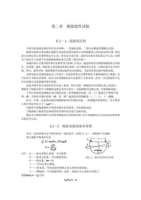
第二章舰船稳性试验§2-1 试验的目的目前用试验确定稳性的方法有两种,一是倾斜试验,二是自由横摇周期测定试验。
倾斜试验的目的是测定舰船在试验状态的初稳性并求得舰艇重心的实际高度位置。
用试验方法确定重心位置和稳定中心高二者是结合进行的,试验的直接结果是稳定中心高,而测定了稳定中心高就可以较准确地确定重心位置(垂向坐标)。
舰艇的重心位置对稳性和浮态都有重大影响,在设计、建造和使用中都要将舰船重心控制在一定范围。
通常,舰船重心是用载重表算出来的,由于载荷项目过多,计算结果往往不很可靠,所以,通常对每一舰船都要用实船试验的办法来确定,为此而作的试验叫倾斜试验。
这种试验应在舰船建造完工后进行,以便获得重心位置和稳性方面准确的完工数据。
这不仅对于本舰是重要的,对以后同型舰船的设计也提供了宝贵资料。
此外,当发现稳性不足时也是拟订改进措施的基本依据。
试验安排在系泊试验阶段并在海上航渡、航行试验、潜艇的首次试潜定重之前进行。
潜艇水下倾斜试验可与潜艇的试潜定重结合进行,先做潜艇的试潜定重,后做倾斜试验。
下列几种情况的舰艇应进行倾斜试验:新型舰艇首制舰,同一工厂批量生产舰船中的第一艘,后续每五艘中的第一艘。
同一船厂建造的同型潜艇第一、二、六、十一艘艇。
经大、中修,改装或加装的每艘舰船均应作倾斜试验。
(如潜艇改装修理后,其计算重心垂向坐标变化大于1cm时)。
对服役中的舰船稳性不明或对稳性有怀疑者,应作倾斜试验。
当舰船缺乏载重状态和稳性的资料时也应进行这种试验。
测定自由横摇周期不仅对新型舰艇是必须的特征量,对小型舰艇还可以由此近似换算得出稳定中心高。
§2-2 倾斜试验的基本原理若以一定的重物Q水平横向移动一段距离D(见图2-1),使舰船产生倾斜,那么根据平衡条件应有Q D Ph⋅⋅=cos sinθθhQD Ptg =θ式中Q——移动重物之重量,可以称得;D——移动之距离,可以测量得到;图2-1 稳性试验原理示意图P——排水量,P=γV;γ——可用比重计测量;V——排水量,可按试验时测得之吃水查排水量曲线;θ——横倾角,可以测量得到,这样一来稳定中心高就可求得了。
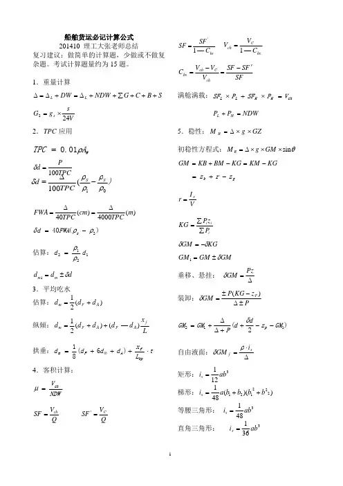
船舶货运必记计算公式201410理工大张老师总结复习建议:做简单的计算题,少做或不做复杂题。
考试计算题量约为15题。
1.重量计算SB C G NDW DW L L +++∑++Δ=+Δ=ΔVsg G s 242×=2.应用TPC WA TPC ρ01.0=TPCP d 100=δ)(4000)(40m TPCcm TPC FWA Δ=Δ=)(402ρρδ−=s FWA d 估算:1212d d ρρ=dd d m m δ±=13.平均吃水估算:)(21A F m d d d +=纵倾:L x d d d d d f A F A F m )—()(21++=拱垂:t L x d d d d bpf A F m ⋅+++=⊗)6(814.客积计算:NDWV ch=μQV SF ch =QV SF C ='bsC SF SF —1'=bsC ch C V V —1=SFF S SF V V V C ch C ch bs ′−=−=满舱满载:chH H L L V P SF P SF =×+×NDWP P H L =+5.稳性:GZg MR××Δ=初稳性方程式:θsin ×××Δ=GM g M R KGKM KG BM KB GM −=−+=gb z r z −+=VI r x =iii P z P KG ∑∑=KGGM δδ−=GMGM GM δ±=1垂移、悬挂:Δ=Pz GM δ装卸:Pz KG P GM P ±Δ−±=)(δ)2(112GM z d d P GM GM p −−++ΔΔ+=δ自由液面:Δ⋅=xf i GM ρδ矩形:3121ab i x =梯形:))((481222121b b b b a i x ++=等腰三角形:3481abi x =直角三角形:3361ab i x =)TPC d S S 01(100ρρρρδ−Δ=圆形:441r i x ⋅=π椭圆:341ab i x π=设纵舱壁:)n i n i xoxn 等分(12=互换:⎪⎭⎪⎬⎫⎪⎩⎪⎨⎧⋅=⋅Δ⋅−=L L H H L H SF P SF P z )P (P GM δ横移:GM pytg ⋅Δ=θ装卸:11GM y p tg p ⋅Δ⋅=θ装卸(重大件):11GM y p py tg b b ⋅Δ⋅+=θ大倾角稳性:θSin KG KN KH KN GZ ⋅−=−=Wh W h l l M M K minmin ==Ww w W Z A P M ⋅⋅=gM l W W ⋅Δ=横摇周期:GMKG B fT 22458.0×+=θ或GMB f T ⋅=θ剩余稳性力臂MS :θSin GM GZ MS ⋅−=6.抗沉性渗透率:体积V Vv 1=μ面积aa a 0=μ许可舱长:F l l F P ⋅=破舱稳性:g b GM GM ⋅ΔΔ=1进水重量:LBDP v ⋅⋅⋅=δμρ进水速率:hH F Q −=μ43.47.强度:每货舱货物重量计算:调整值±Σ⋅Σ=Q V V P chichii 拱垂值:m m d d −=⊗δ局部强度:允许值上甲板:SFgH r H g P C cC ⋅⋅=α或 1.5t /m 2,14.7kP a货舱:cC d r H g P ⋅⋅=或:)(72.0αkP H g P d d ⋅⋅=实际:'dd P P ≤)(2min m P PA d=7.吃水差:MTCM t L 100=δMTCx x g t b g 100)(−⋅Δ=δtt t δ+=1装卸:MTCx x g P t f P 100)(−⋅⋅=δ移动:MTCxPg t 100⋅=δ装卸后:tLx TPC p d d d d d fF Fm F F δδδ⋅−+±=++=)21(1001tLx TPC p d d d d d fA Am A A δδδ⋅+−±=++=)21(1001IMO 要求:⎩⎨⎧+≥≥≤202.0025.0150min min L d L d mL m F (m)⎩⎨⎧+≥+≥>202.02012.0150min min L d L d mL m F (m )吃水差比尺:100'Pd d F F ±⋅=δδ100'Pd d A A ±⋅=δδ8.系固道数:MSLPN y =9.谷物稳性计算:GMg M tg u⋅⋅Δ='θ∑⋅=ivivi u SF M C M '⎪⎩⎪⎨⎧=12.106.100.1vi C g M uO ⋅Δ='λ0408.0λλ×=404040λ−=′GZ Z G 10.固体散货:最大吃水:a W d D H D D −+=max 最小吃水:潮高安全距离机船W H h h H D ′++−=21min 排水量的水密度修正1025.1Δ=Δρ装卸量计算:装:)()(F F A A G G Q −Δ−−Δ=卸:)()(A A F F G G Q −Δ−−Δ=11.油量计算:膨胀余量:tf t f VV δδδ⋅+⋅=1最大装油体积:VV V t a t δ−=.换算:⎪⎩⎪⎨⎧+=−=)44.4(00096.160/60.54/15.20020γραρF G S C G S )20(20−−=t t γρρ空档修正:横向θtg AC AB ⋅=纵向Lt AC AB ⋅=空档高度=测量值AB±油轮要求:⎩⎨⎧<+>⊗Lt m L d m015.011)(202.0油温测量:53dm u t t t t ++=油量计算:2020)0011.0(V m ⋅−=ρ2020V F m ⋅⋅=ρ以第2式为准。
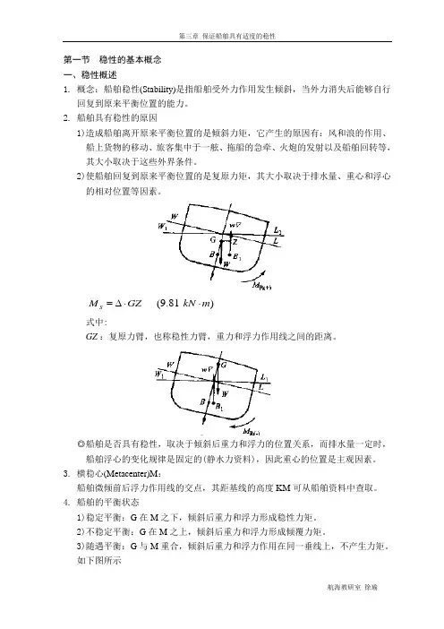
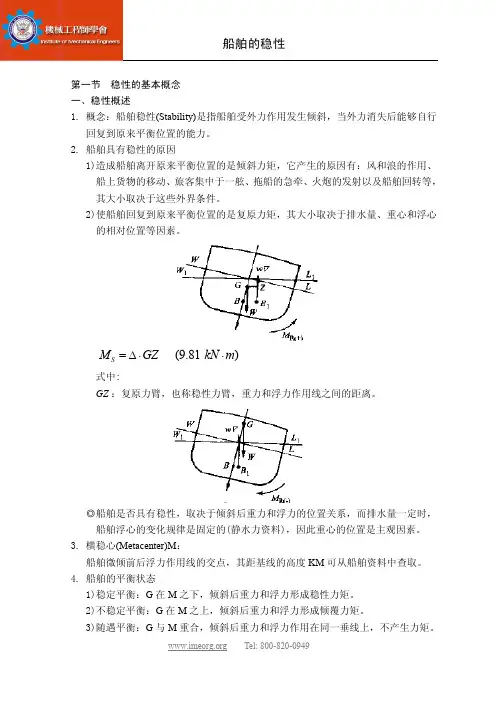
第一节 稳性的基本概念 一、稳性概述1. 概念:船舶稳性(Stability)是指船舶受外力作用发生倾斜,当外力消失后能够自行回复到原来平衡位置的能力。
2. 船舶具有稳性的原因1)造成船舶离开原来平衡位置的是倾斜力矩,它产生的原因有:风和浪的作用、船上货物的移动、旅客集中于一舷、拖船的急牵、火炮的发射以及船舶回转等,其大小取决于这些外界条件。
2)使船舶回复到原来平衡位置的是复原力矩,其大小取决于排水量、重心和浮心的相对位置等因素。
S M GZ =∆⋅ (9.81)kN m ⋅式中:GZ :复原力臂,也称稳性力臂,重力和浮力作用线之间的距离。
◎船舶是否具有稳性,取决于倾斜后重力和浮力的位置关系,而排水量一定时,船舶浮心的变化规律是固定的(静水力资料),因此重心的位置是主观因素。
3. 横稳心(Metacenter)M :船舶微倾前后浮力作用线的交点,其距基线的高度KM 可从船舶资料中查取。
4. 船舶的平衡状态1)稳定平衡:G 在M 之下,倾斜后重力和浮力形成稳性力矩。
2)不稳定平衡:G 在M 之上,倾斜后重力和浮力形成倾覆力矩。
3)随遇平衡:G 与M 重合,倾斜后重力和浮力作用在同一垂线上,不产生力矩。
如下图所示例如:1)圆锥在桌面上的不同放置方法;2)悬挂的圆盘5. 船舶具有稳性的条件:初始状态为稳定平衡,这只是稳性的第一层含义;仅仅具有稳性是不够的,还应有足够大的回复能力,使船舶不致倾覆,这是稳性的另一层含义。
6. 稳性大小和船舶航行的关系1)稳性过大,船舶摇摆剧烈,造成人员不适、航海仪器使用不便、船体结构容易受损、舱内货物容易移位以致危及船舶安全。
2)稳性过小,船舶抗倾覆能力较差,容易出现较大的倾角,回复缓慢,船舶长时间斜置于水面,航行不力。
二、稳性的分类1. 按船舶倾斜方向分为:横稳性、纵稳性2. 按倾角大小分为:初稳性、大倾角稳性3. 按作用力矩的性质分为:静稳性、动稳性4. 按船舱是否进水分为:完整稳性、破舱稳性三、初稳性1. 初稳性假定条件:1)船舶微倾前后水线面的交线过原水线面的漂心F;2)浮心移动轨迹为圆弧段,圆心为定点M(稳心),半径为BM(稳心半径)。
第三章船舶稳性1.某轮某航次出港时的初稳性高度GM=0.56米,临界稳性高度GMc=0.75米,则该轮的不满足《船舶与海上设施法定检验规则》对普通货船的基本稳性要求。
A 初稳性B 动稳性C 大倾角稳性D B、C均有可能2.某轮某航次出港时的初稳性高度GM=0.56米,临界稳性高度GMc=0.75米,该轮的一定满足《船舶与海上设施法定检验规则》对普通货船的基本稳性要求。
A 初稳性B 动稳性C 大倾角稳性D 以上都是3.要使船舶处于不稳定平衡状态,必须满足的条件是。
A GM = OB GM < 0C GM > OD GM ≥ 04.要使船舶处于不稳定平衡范畴,必须满足的条件是。
A GM = OB GM < 0C GM > OD GM ≤ 05.我国《船舶与海上设施法定检验规则》中规定:船舶受稳定横风作用时的风压倾侧力矩可用公式M W=P W A W Z W 来计算,其中Z W是指。
A A W的中心至水下侧面积中心的垂直距离B A W的中心至船舶水线的垂直距离C A W的中心至船舶吃水的一半处的垂直距离D A或C6. 将增加船舶的浮心高度。
A 由舱内卸货B 向甲板上装货C 将货物上移D 将货物下移7.GM是船舶初稳性的度量,因为。
A 当船舶倾角为大倾角时稳心基本不随船舶倾角改变而改变B 当船舶倾角为大倾角时稳心随船舶倾角改变而改变C 当船舶倾角为小倾角时稳心基本不随船舶倾角改变而改变D 当船舶倾两为小倾角时稳心随船舶倾角改变而改变8.初稳性是指。
A 船舶在未装货前的稳性B 船舶在小角度倾斜时的稳性C 船舶在开始倾斜时的稳性D 船舶在平衡状态时的稳性9.船舶舱室破损后仍浮在水面并保持一定浮态和稳性的能力称为船舶。
A 浮性B 稳性C 抗沉性D 储备浮力10.船舶侧向受风面积。
A 随吃水的增加而减小B 随吃水的增加而增大C 与吃水大小无关D 与吃水的关系不能确定11.船舶的稳心半径BM与成反比。
一、概述本船为航行于内河B级航区的一条旅游船。
现按照中华人民共和国海事局《内河船舶法定检验技术规则》(2004)第六篇对本船舶进行完整稳性计算。
二、主要参数总长L OA13.40 m垂线间长L PP13.00 m型宽 B 3.10 m型深 D 1.40 m吃水 d 0.900 m排水量∆ 17.460 t航区内河B航区三、典型计算工况1、空载出港2、满载到港五、受风面积A六、旅客集中一弦倾侧力矩L KL K=1∆(1−n5lb)=0.030 mn lb =1.400<2.5,取nlb=1.400式中:C—系数,C=0.013lbN=0.009<0.013,取C=0.013n—各活动处所的相当载客人数,按下式计算并取整数n=NSbl=28.000S—全船供乘客活动的总面积,m2,按下式计算:S=bl=20.000 m2b—乘客可移动的横向最大距离,b=2.000 m;l—乘客可移动的横向最大距离,b=2.000 m。
七、全速回航倾侧力矩L VL V=0.045V m2L S[KG−(a2+a3F r)d]KN−m式中:Fr—船边付氏数,F r=m9.81L;Ls—所核算状态下的船舶水线长,m;d—所核算状态下的船舶型吃水,m;∆—所核算状态下的船舶型排水量,m2;KG—所核算状态下的船舶重心至基线的垂向高,m;Vm—船舶最大航速,m/s;a3—修正系数,按下式计算;a3=25F r−9当a3<0,取a3=0;当a3>1时,取a3=1;a2—修正系数,按下式计算;a2=0.9(4.0−Bs/d)当Bs/d<3.5时,取Bs/d=3.5;当Bs/d>4.0时,取Bs/d=4.0;。