共立3132A中文使用说明书
- 格式:pdf
- 大小:510.24 KB
- 文档页数:11
DEVICE SPECIFICATIONSIC-3121Industrial ControllerThis document provides the specifications for the IC-3121. Specifications are subject to change without notice. Refer to the National Instruments Product Manuals Library at / manuals for the most recent versions of product documentation.Characteristics/Nominal Specifications describe basic functions and attributes of the device established by design.Physical CharacteristicsCaution You can impair the protection provided by the IC-3121 if you use it in amanner not described in this document.To clean the IC-3121, wipe it with a dry towel.Dimensions10.8 cm × 6.1 cm × 13.0 cm (4.3 in × 2.4 in ×5.1 in)Weight911 g (2.01 lb)ProcessorType Quad Core Intel Atom Processor E3845 Frequency 1.91 GHzOn-die L2 cache 2 MBOperating SystemSupported Operating Systems NI Linux Real-Time 64-bitWindows Embedded Standard 7 64-bitMemorySystem RAMCapacity 4 GBType DDR3LSpeed1333 MT/sNonvolatile storageCapacity 2 GBPower RequirementsNote Supply voltages are measured at the IC-3121 power connectors.System Power (V)Supply voltage10.8 to 26.4 VDCMaximum power input24 WIsolated Output Power (V ISO)Supply voltage 4.5 to 30 VDCReconfigurable FPGAType Spartan-6 LX25Number of flip-flops30,064Number of 6-input LUTs15,03238Number of DSP48E1 slices(18 × 25 multipliers)Embedded block RAM52 (936 Kbits)Number of DMA channels32Number of logical interrupts322| | IC-3121 SpecificationsNetwork PortStandard IEEE 802.3 Ethernet, 10BASE-T, 100BASE-TX, 1000BASE-TInterface RJ45Speed10, 100, 1000 MbpsUSB 3.0 PortsNumber of ports2Type USB 3.0, SuperSpeedSpeed 5 Gbit/sMaximum current900 mA, per portUSB 2.0 PortsNumber of ports2Type USB 2.0, Hi-SpeedSpeed480 Mbit/sMaximum current 1 A, shared across both portsVGA PortMaximum resolution1920 × 1200 at 60 HzTTL Inputs/OutputsNumber of channels8Type BidirectionalOutput voltage range0 V to 5 VMaximum pulse rate 2 MHzMinimum pulse detected500 nsPower-on state Input (high-impedance), 10 kΩ pull-up to 5 VIC-3121 Specifications| © National Instruments| 3Logic levelsInput low voltage0.59 V maximumInput high voltage 2.57 V minimumOutput low voltage0.38 V maximum at 1.5 mAOutput high voltage 4.12 V minimum at 1.5 mADifferential Inputs/OutputsNumber of channels2Types Bidirectional RS-422/RS-485 or single-endedinputMaximum pulse rate 5 MHz, differentialDifferential input threshold±200 mVDifferential output voltage 2.0 V min (R LOAD = 100 Ω, RS-422)Input voltage range0 V to 5.5 VTTL-compatible single-ended logic levelsInput low voltage0.8 VInput high voltage 2.0 VIsolated InputsType Current sinkingNumber of channels8Input voltageInput voltage range0 V to 24 VInput OFF voltage0 V to 2.0 VInput ON voltage 3.3 V to 24 VTurn-on current 2.5 mAMaximum pulse rate100 kHzMinimum pulse detected10 µsInput protectionReverse polarity protection Yes, -30 VInput voltage (channel to C ISO)30 V maximumInput current 3.3 mA, internally limited4| | IC-3121 SpecificationsIsolated OutputsType Current sourcingNumber of channels8Supply voltage (V ISO)Supply voltage range (V ISO) 4.5 to 30 VDCReverse polarity protection Yes, -30 VMaximum output voltage dropV ISO = 5 V 1.08 V at 35 mAV ISO = 24 V 1.18 V at 80 mAMaximum output currentV ISO = 5 V35 mAV ISO = 24 V80 mAMaximum current limit345 mAMinimum pulse rate 2.5 kHz (load of 100 kΩ, 300 pF)Maximum pulse rate20 kHz (load of 10 kΩ, 300 pF)Minimum pulse generated400 µsNote The isolated outputs have a current limit which will turn off the outputs incase the limit is exceeded. The circuit resets when the output is turned off. Do notdraw more than 100 mA from any 24 V isolated output. Do not draw more than50 mA from any 5 V isolated output. Do not draw more than 640 mA combinedfrom the V ISO pins on the 44-pin D-SUB connector.EnvironmentalIndoor use only.Ingress protection (IEC 60529)IP40Temperature (IEC 60068-2-1 and IEC 60068-2-2)Operating0 °C to 55 °CStorage-20 °C to 85 °COperating humidity (IEC 60068-2-56)10% RH to 90% RH, noncondensing Storage humidity (IEC 60068-2-56)5% RH to 95% RH, noncondensing Pollution degree (IEC 60664)2IC-3121 Specifications| © National Instruments| 5Maximum Altitude2,000 mOperating shock (IEC 60068-2-27)50 g, 3 ms half sine, 3 shocks per side 30 g, 11ms half sine, 3 shocks per sideOperating vibrationRandom (IEC 60068-2-64)10 to 500 Hz, 5 g rmsSwept Sine (IEC 60068-2-6)10 to 500 Hz, 5 gSafetyThis product is designed to meet the requirements of the following electrical equipment safety standards for measurement, control, and laboratory use:•IEC 61010-1, EN 61010-1•UL 61010-1, CSA C22.2 No. 61010-1Note For UL and other safety certifications, refer to the product label or the OnlineProduct Certification section.Electromagnetic CompatibilityThis product meets the requirements of the following EMC standards for electrical equipment for measurement, control, and laboratory use:•EN 61326-1 (IEC 61326-1): Class A emissions; Industrial immunity•EN 55011 (CISPR 11): Group 1, Class A emissions•AS/NZS CISPR 11: Group 1, Class A emissions•FCC 47 CFR Part 15B: Class A emissions•ICES-001: Class A emissionsNote In the United States (per FCC 47 CFR), Class A equipment is intended foruse in commercial, light-industrial, and heavy-industrial locations. In Europe,Canada, Australia and New Zealand (per CISPR 11) Class A equipment is intendedfor use only in heavy-industrial locations.Note Group 1 equipment (per CISPR 11) is any industrial, scientific, or medicalequipment that does not intentionally generate radio frequency energy for thetreatment of material or inspection/analysis purposes.Note For EMC declarations and certifications, and additional information, refer tothe Online Product Certification section.6| | IC-3121 SpecificationsCE ComplianceThis product meets the essential requirements of applicable European Directives, as follows:•2014/35/EU; Low-V oltage Directive (safety)•2014/30/EU; Electromagnetic Compatibility Directive (EMC)Online Product CertificationRefer to the product Declaration of Conformity (DoC) for additional regulatory compliance information. To obtain product certifications and the DoC for this product, visit / certification, search by model number or product line, and click the appropriate link in the Certification column.Environmental ManagementNI is committed to designing and manufacturing products in an environmentally responsible manner. NI recognizes that eliminating certain hazardous substances from our products is beneficial to the environment and to NI customers.For additional environmental information, refer to the Minimize Our Environmental Impact web page at /environment. This page contains the environmental regulations and directives with which NI complies, as well as other environmental information not included in this document.Waste Electrical and Electronic Equipment (WEEE)EU Customers At the end of the product life cycle, all NI products must bedisposed of according to local laws and regulations. For more information abouthow to recycle NI products in your region, visit /environment/weee.Battery Replacement and DisposalBattery Directive This device contains a long-life coin cell battery. If you need toreplace it, use the Return Material Authorization (RMA) process or contact anauthorized National Instruments service representative. For more information aboutcompliance with the EU Battery Directive 2006/66/EC about Batteries andAccumulators and Waste Batteries and Accumulators, visit /environment/batterydirective.IC-3121 Specifications| © National Instruments| 7电子信息产品污染控制管理办法(中国RoHS)中国客户National Instruments符合中国电子信息产品中限制使用某些有害物质指令(RoHS)。
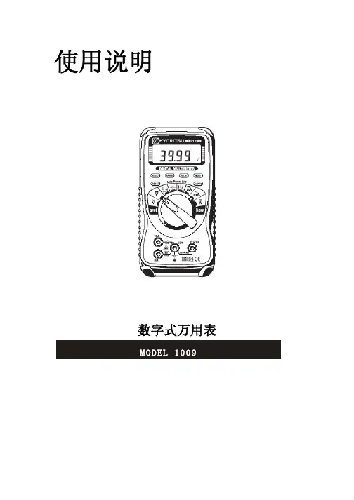
使用说明数字式万用表MODEL 10091.安全警告本仪器根据以下标准进行设计、生产,并且于检查合格后在最好状态下出货。
IEC 61010-1过电压CAT III300V污染度2IEC 61010-031IEC 61326本说明书包含警告和安全规则,记载了避免人身伤害事故和保持仪器能在长期良好状态下使用的注意事项。
因此,使用仪器前请仔细阅读操作指南。
警告● 使用前,通读并理解说明书中的操作指南。
● 请将说明书随身保存以确保可随时参阅。
● 必须由专业工作人员使用并严格遵守使用说明书中的安全指示进行操作。
对任何因错误使用或未遵守使用说明书中记载的注意事项而引起的损伤、人身事故,共立公司概不负责。
● 理解并遵守安全操作指示。
必须严格遵守上述操作说明。
如不遵守,测量时可能会导致人身伤害和仪器毁坏。
仪器上标志,提醒用户在操作时,必须参阅相关操作说明。
标志分为3种,请注意阅读其不同内容。
危险:表示操作不当会导致严重或致命的伤害。
警告:表示操作不当存在导致严重或致命的伤害的可能性。
小心:表示操作不当有可能会导致人身伤害或仪器毁坏。
危险●请勿在对地电压AC300V以上的电路中测量。
●请勿在充满可燃性气体的环境里进行测量。
可能会产生火花引起爆炸。
●测试时,请注意务必使手指位于测试线的安全栅后。
●请勿在仪器表面或手潮湿的情况下使用。
●测量时,请勿打开电池盖。
警告●请勿在非正常情况下进行测量,例如:仪器机体损坏,仪表或测试线金属部件的裸露。
●测试线连接在被测物上时,请勿切换量程开关。
●请勿在仪器上安装替换部件或对仪器进行改造。
如果仪器损坏,请将其返回当地经销商进行检修。
●仪器表面潮湿的情况下,请勿更换电池。
●请将量程开关转到“OFF”并取下测试线后,打开电池盖更换电池。
注意●测量前,请将量程开关转到适当位置。
●请勿将仪表暴露在阳光、高温、潮湿、露水的环境里。
●长期不使用或储藏时,取下电池。
●请勿使用研磨剂或有机溶剂进行清洗,必须使用中性洗剂或湿抹布清洗。
3124高压兆欧表使用说明书目录1.安全上的警告2.特点3.规格4.仪器面板5.测试前的准备6.操作须知7.电池充电8.更换电池9.镍镉电池的储藏10.记录器的连接1.安全上的警告z本操作手册包含了警告讯息及安全规定,当使用本机时请确实遵守,以确保使用者的操作安全及仪器安全,因此于使用本机前请先仔细地彻底的阅读本手册。
z本手册中表示.符号,提醒读者必须参考手册中的相关章节,确保操作安全。
z请特别注意本手册中WARNINGS及CAUTIONS的提示,WARNINGS表示要小心触电的危险而CAUTION表示须注意仪器的损坏。
z绝缘测试是用来测试已断电的电路(死线)或装置,请不要在有电的情况下(活线)做测试。
z在每次测试时请切记待测电路或装置必须是不带电的,请确认您可以清楚的看到待测电路或装置已与电力系统切离,,在作绝缘测试前,在尚未确认是否带电时请勿做任何测试。
z如果您不知道如何开始特高阻测试(高压)请先与待测设备的制造商讨论,有些设备装置了高敏度的电子元件,可能在高直流的电压下造成损坏,原制造商可事先对此提出警告避免此种损坏。
z本测试器能产生10KV的直流高电压,于测试时请不要接触测试导线或被测设备.请不要尝试用本机器去刺激或惊吓别人.潮湿的环境,流水的水笼都有可能造成触电而导致心脏停止。
z于测试时请不要打开电池盒盖。
z请时常注意您的仪器,测试导线以及其它附件是否有损坏的痕迹或变形,如果有任何异常发生(如:导线破损、机壳裂缝、显示屏幕无法读取等),请不要进行任何测试。
z在做测试的过程中请注意不要让自己成为接地的通路,不要接触外露的金属管,出水口、固定物等,它们可能会让您成为接地电位。
另外请将您的身体与大地隔绝,例如使用干布、绝缘鞋、绝缘毯或其它保证绝缘的物质。
z为避免触电事故,在工作电压高于40VDC或20V AC时请使用警告标志。
z在连接测试导线及探棒前请先确认功能选择钮是否位于OFF的位置,测试键并没有被压下或在锁定位置。
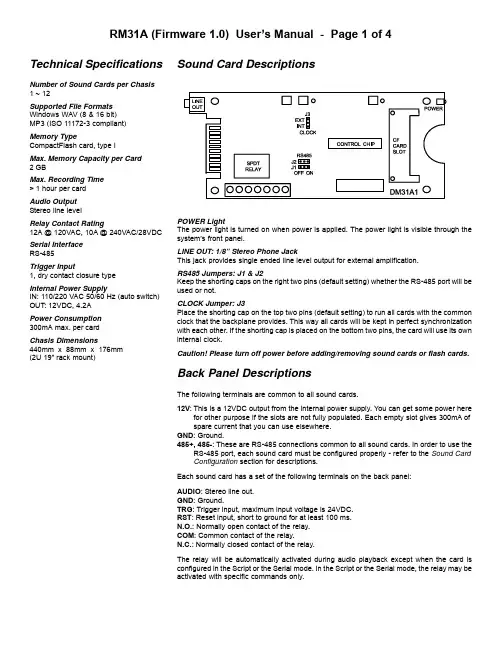
Sound Card DescriptionsPOWER LightThe power light is turned on when power is applied. The power light is visible through the system’s front panel.LINE OUT: 1/8” Stereo Phone JackThis jack provides single ended line level output for external amplification.RS485 Jumpers: J1 & J2Keep the shorting caps on the right two pins (default setting) whether the RS-485 port will be used or not.CLOCK Jumper: J3Place the shorting cap on the top two pins (default setting) to run all cards with the common clock that the backplane provides. This way all cards will be kept in perfect synchronization with each other. If the shorting cap is placed on the bottom two pins, the card will use its own internal clock.Caution! Please turn off power before adding/removing sound cards or flash cards.Back Panel DescriptionsThe following terminals are common to all sound cards.12V :This is a 12VDC output from the internal power supply. You can get some power herefor other purpose if the slots are not fully populated. Each empty slot gives 300mA of spare current that you can use elsewhere.GND : Ground.485+, 485-: These are RS-485 connections common to all sound cards. In order to use theRS-485 port, each sound card must be configured properly - refer to the Sound Card Configuration section for descriptions.Each sound card has a set of the following terminals on the back panel:AUDIO : Stereo line out.GND : Ground.TRG : Trigger input, maximum input voltage is 24VDC.RST : Reset input, short to ground for at least 100 ms.N.O.: Normally open contact of the : Common contact of the relay.N.C.: Normally closed contact of the relay.The relay will be automatically activated during audio playback except when the card is configured in the Script or the Serial mode. In the Script or the Serial mode, the relay may be activated with specific commands only.Technical SpecificationsNumber of Sound Cards per Chasis 1 ~ 12Supported File Formats Windows WAV (8 & 16 bit)MP3 (ISO 11172-3 compliant)Memory TypeCompactFlash card, type I Max. Memory Capacity per Card 2 GBMax. Recording Time > 1 hour per card Audio Output Stereo line levelRelay Contact Rating12A @ 120VAC, 10A @ 240VAC/28VDC Serial Interface RS-485Trigger Input1, dry contact closure typeInternal Power SupplyIN: 110/220 VAC 50/60 Hz (auto switch)OUT: 12VDC, 4.2A Power Consumption 300mA max. per card Chasis Dimensions440mm x 88mm x 176mm (2U 19” rack mount)Operation ModesEach sound card can be configured independently to operate in one of the following modes. A simple text based configuration file needs to be created on the flash card unless the default mode (SN) is to be used.Simple ModeThis mode utilizes a “normally open” device (such as push button, motion sensor or any device capable of producing a dry contact closure) for triggering. Simply connect one pole of the device to the trigger input (TRG) and the other pole to the ground (GND). The system gets triggered when the two poles are closed (con-nected to each other).Upon power-up or reset, the first trigger will play the first file (file #001). The second trigger will either play the next file (file #002) if it exists, or the first file (file #001) if the next file does not exist. The relay, which can be used to turn on a lamp or a motor, will be activated during the playback.The system will play continuously if the trigger input is tied to the ground permanently.Variation 1 - SN Mode (default)In this mode, applying trigger during playback will have no effect. No system configuration is necessary to operate in this mode. Variation 2 - SN+ ModeSame as the SN mode but triggering is done by opening the poles instead of closing them.Variation 3 - SI ModeIn this mode, applying trigger during playback will interrupt it and start playing the next file immediately.Variation 4 - SI+ ModeSame as the SI mode but triggering is done by opening the poles instead of closing them.Variation 5 - SH ModeIn this mode, the playback continues for as long as the trigger is applied. The playback stops as soon as the trigger is removed. Variation 6 - SH+ ModeSame as the SH mode but triggering is done by opening the poles instead of closing them.Script ModeLike the Simple mode, the Script mode also utilizes a “normally open” device for triggering. However, instead of just playing a sound, the Script mode allows the execution of a number of commands such as playing sound, turning on/off the relay and waiting some time. Please see the Script Mode section for details.Variation 1 - DS ModeThis is the regular Script mode.Variation 2 - DS+ ModeSame as the DS mode but triggering is done by opening the poles instead of closing them.Serial ModeIn this mode the sound card can be controlled remotely via the RS-485 port. Please see the Serial Mode section for details.Sound Card ConfigurationBy default, the sound card works in the SN mode.To operate it in other modes, you need to create a plain ASCII text file named “MODE.TXT” on its flash card. This file should contain one of the following mode names on the first line.SN+, SI, SI+, SH, SH+, DS, DS+For the Serial mode, replace the mode name with a two-digit serial ID number ranging from “01” to “99”. You will also need to open the unit and move internal jumpers J1 and J2 to the “ON” position. For the Script mode, enter the script starting from the second line. Use all capital letters and be sure to add the word END at the end of the script.After editing, the configuration file should be saved as “plain text file”, “ASCII text file”, or simply “text file”. It is important to not save any text formatting information in the file.File Number AssignmentEach sound file on the flash card must be assigned a unique file number for identification purpose. The file numbers must be three digits long starting from 001 and up. If you want to play more than one files, they should be numbered consecutively from 001. Sim-ply add the file number to the beginning of the original filename, e.g. “001oldname.wav”.Trouble Shooting Guide1. Plays no sound at all.a.File numbers are not assigned properly.b.The sound card is in the wrong mode due to missing orincorrect configuration file.c.If the flash card is inserted when the power is on, the systemwill not work. To fix this problem, turn the power off for a few seconds to reset the system.d.Some CF cards, especially if they have been used in digitalcameras, need to be reformatted with the FAT16 file system.Also, some CF cards may be incompatible - try a differentbrand of CF card.e.The audio output is at line level and needs to be amplifiedexternally in order to drive speakers.f.The sound file is in an unsupported format.2. Plays a wrong sound.a.File numbers are not assigned properly.b.The system is in the wrong mode due to missing or incorrectconfiguration file.3. Sound quality is poor with lots of noise.The flash card’s speed may be too slow - try a different brand. This problem is more likely to happen when playing high bit rate audio such as 44.1 KHz WAV files.4. In the Serial mode, the DTE device receives wrong or no responses.Make sure the DTE device’s serial port setting is 9600 baud, 8 data bits, no parity, 1 stop bit.Script ModeThe Script mode is used in advanced applications to activate a number of actions with a single trigger. Note that the relay will not turn on/off automatically in the Script mode. It may be turned on/off using the BN/BF script commands.Written in the configuration file (MODE.TXT) using plain ASCII text, the script consists of multiple lines each containing the commands for a particular script number in the following format:nnn=Command1,Command2...Here “nnn” is the script number ranging from 001 to 999, and “?” is one of the following:N - Non-interruptibleExecution of this script is not interruptible.I - InterruptibleExecution of this script is interruptible by a second trigger.H - HoldableExecution of this script continues for as long as the trigger is ap-plied, repeating if necessary. The execution stops immediately when the trigger is removed.Script 000, if defined, is executed once automatically when the system powers up or after the system is reset. Script 001 is ex-ecuted when the TRG input is triggered. Other scripts (002 and up) can be executed when they are jumped to.The following are the script commands:Fnnn - play File #nnnExample: F168 plays file #168.Wnnnnn - wait nnnnn units of 0.1 secondExample: W00020 waits 2 seconds.Jnnn - jump to script #nnnExample: J007 jumps to script 007.BF - turn off the relayBN - turn on the relayENDAlways add the word END at the end of the script file. You may add any comments for your own reference after END.Notes- Script lines must be separated by carriage returns (the Enter key). - A script line is limited to 128 characters, excluding ‘=’ and ‘,’. If more space is needed, use the Jump command to cascade the commands.ExampleDSN001=F007,BN,W00030,F899,BF,J168I168=F001,W36000,J168H033=F273ENDDS is not really a script command, but it tells the system to enter the Script mode.When triggered, the sound card executes script 001. Since this script is non-interruptible (because of the letter N in front of 001), it will always be completely executed as the following:- play file #007,- wait 3 seconds,- turn on the relay,- play file #899,- turn off the relay,- jump to script 168.Script 168 is executed as the following:- play file #001,- wait 60 minutes,- jump back to itself.Since script 168 is interruptible (because of the letter I in front of 168), this endless loop can be broken with a second trigger. Script 033 will never be executed because it is not jumped to by any executable script.Automatic Execution of Script 000Upon power-up or reset, the sound card will automatically executes script 000 once if it exists.Playing Background MusicThe automatic execution feature can be used to play background music while no trigger is being executed. For example, DSI000=F123,J000N001=F001,J000ENDHere file #123 is loop played from power-up but will be interrupted when the input is triggered. After interruption, the script jumps back to 000 so file #123 starts to play again, although from the begin-ning instead of where it left off.Serial ModeThe serial interface is RS-485. In order to enable it, you must move the internal jumpers J1 and J2 on each sound card to the “ON”position. Also, the configuration file (MODE.TXT) must contain a two-digit device number ranging from “01” to “99”.The hardware protocol is 9600 baud, 8 data bits, no parity and 1 stop bit. The communication employs software flow control on a per-byte basis. That is, for every byte it receives, the player (work-ing as a DCE) returns a confirmation byte. The DTE must not send the next byte until it receives the confirmation.A communication session always starts with a selection process. The DTE first sends out an ASCII “A” which, as the only exception, will not be confirmed by any system on the bus. The DTE then sends the device number in binary form (ranging from 1 to 99). If there is a system with the matching number, it will respond by send-ing back an ASCII “a” within 100 ms. Otherwise the selection pro-cess has failed and should be restarted.Once the selection process is finished successfully, the DTE can start sending one of the serial commands, one byte at a time. For each byte sent, the DTE should expect to receive a proper confir-mation within 100 ms. If the confirmation is missing or invalid, the whole session should be aborted.Testing the Serial InterfaceThe serial port can be easily tested by using a Windows utility pro-gram called “HyperT erminal”. HyperTerminal allows you to send and receive data through the PC’s serial port. Refer to its help menu for more information.The first step is to create a text file called “MODE.TXT” on the flash card. Put only two letters in the file: 66. This will put the player into the Serial mode with a device number of 66. You also need to put a test sound file on the flash card named 001.WAV (or 001.MP3). The next step is to connect the player to the PC using a proper cable. If the PC does not have a RS-485 port, install a RS-232 to RS-485 converter.Run HyperTerminal and make a new connection with these param-eters: 9600 baud, 8N1, no flow control. Now we are ready to send the following commands to the player.We Type Player Responds------------------------------------------------------A-B a(see notes below)F f000011At this point the player should start playing the test sound file, and the test is considered successful.Note that we typed a letter B for the device number, because the ASCII code for letter B is 66.If you type a wrong letter during the test, the player will respond either with a letter e or nothing at all, depending on the situation. In this case, you need to restart from the very beginning.Serial Mode CommandsPlay FileDTE Sends: F### (### is the three-digit file number)Player Confirms: f### (### is the same file number as above)If the file exists, it will be played once. If the file does not exist, the system will simply ignore the command.If the system is playing/paused when the ‘F’ letter is received, it will return the error code ‘e’ instead of ‘f’. At this point the command should be aborted. You should use the Stop Playback command to stop the current playback first before starting a new one.Loop PlayDTE Sends: L### (### is the three-digit file number)Player Confirms: l### (### is the same file number as above)If the file exists, it will be played repeatedly. If the file does not exist, the system will simply ignore the command.If the system is playing/paused when the ‘L’ letter is received, it will return the error code ‘e’ instead of ‘l’ (lower case L). At this point the command should be aborted. You should use the Stop Play-back command to stop the current playback first before starting a new one.StopDTE Sends: SSystem Confirms: sIf the system is not playing/paused, it will simply ignore the com-mand. Otherwise it will terminate the current playback.PauseDTE Sends: PSystem Confirms: pIf the system is not playing, it will simply ignore the command. When the system is being paused, its Busy output (terminal BY) is still active.ResumeDTE Sends: RSystem Confirms: rIf the system is not paused, it will simply ignore the command.Busy?DTE Sends: BSystem Confirms: b (if playing or paused) or s (otherwise)ScriptDTE Sends: C### (### is the three-digit script number)System Confirms: c### (### is the same script number as above) If the script number exists in the configuration file, it will be ex-ecuted. If the script number does not exist, the system will simply ignore the command. Refer to the Script Mode section for details on how to write the script.Error CodeThe system will confirm with an “e” if an invalid command is re-ceived, or if a valid command is received at the wrong time. At this point, the command should be aborted.。
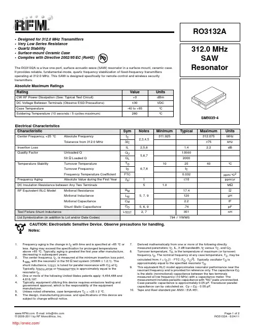
Electrical Characteristics CharacteristicSymNotesMinimumTypical MaximumUnitsCenter Frequency, +25 °C Absolute Frequency f C 2,3,4,5311.925312.075MHz Tolerance from 312.0 MHz∆f C ±75kHz Insertion Loss IL 2,5,6 1.4 2.2dBQuality Factor Unloaded Q Q U 5,6,71350050 Ω Loaded Q Q L 2000Temperature StabilityTurnover Temperature T O 6,7,8102540°C Turnover Frequencyf O f C Frequency Temperature CoefficientFTC 0.032ppm/°C 2Frequency AgingAbsolute Value during the First Year |f A |1≤10ppm/yr DC Insulation Resistance between Any Two Terminals51.0M ΩRF Equivalent RLC ModelMotional Resistance R M 5, 7, 917.4ΩMotional Inductance L M 120µH Motional Capacitance C M 2.2fF Shunt Static CapacitanceC O 5, 6, 9.74pF Test Fixture Shunt InductanceL TEST2, 7351nHLid Symbolization (in addition to Lot and/or Date Codes)794 // YWWS•Designed for 312.0MHz Transmitters •Very Low Series Resistance •Quartz Stability•Surface-mount Ceramic Case•Complies with Directive 2002/95/EC (RoHS)The RO3132A is a true one-port, surface-acoustic-wave (SAW) resonator in a surface-mount, ceramic case. It provides reliable, fundamental-mode, quartz frequency stabilization of fixed-frequency transmitters operating at 312.0MHz. This SAW is designed specifically for remote-control and wireless security transmitters.Absolute Maximum Ratings RatingValueUnitsCW RF Power Dissipation (See: Typical Test Circuit)+0dBm DC Voltage Between Terminals (Observe ESD Precautions)±30VDC Case Temperature-40 to +85°C Soldering Temperature (10 seconds / 5 cycles maximum)260°C312.0 MHz SAW ResonatorRO3132ACAUTION: Electrostatic Sensitive Device. Observe precautions for handling.Notes:1.Frequency aging is the change in f C with time and is specified at +65 °C or less. Aging may exceed the specification for prolonged temperaturesabove +65 °C. Typically, aging is greatest the first year after manufacture, decreasing in subsequent years.2.The center frequency, f C , is measured at the minimum insertion loss point, IL MIN , with the resonator in the 50Ω test system (VSWR ≤ 1.2:1). The shunt inductance, L TEST , is tuned for parallel resonance with C O at f C . Typically, f OSCILLATOR or f TRANSMITTER is approximately equal to the resonator f C .3.One or more of the following United States patents apply: 4,454,488 and 4,616,197.4.Typically, equipment utilizing this device requires emissions testing and government approval, which is the responsibility of the equipment manufacturer.5.Unless noted otherwise, case temperature T C =+25±2°C.6.The design, manufacturing process, and specifications of this device are subject to change without notice.7.Derived mathematically from one or more of the following directly measured parameters: f C , IL, 3dB bandwidth, f C versus T C , and C O .8.Turnover temperature, T O , is the temperature of maximum (or turnover) frequency, f O . The nominal frequency at any case temperature, T C , may be calculated from: f =f O [1-FTC (T O -T C )2]. Typically oscillator T O is approximately equal to the specified resonator T O .9.This equivalent RLC model approximates resonator performance near the resonant frequency and is provided for reference only. The capacitance C O is the static (nonmotional) capacitance between the two terminals measured at low frequency (10MHz) with a capacitance meter. Themeasurement includes parasitic capacitance with "NC” pads unconnected. Case parasitic capacitance is approximately 0.05pF. Transducer parallel capacitance can by calculated as: C P ≈C O -0.05pF.10.Tape and Reel standard per ANSI / EIA 481.PbElectrical ConnectionsThe SAW resonator is bidirectional and may beinstalled with either orientation. The two terminalsare interchangeable and unnumbered. The calloutNC indicates no internal connection. The NC padsassist with mechanical positioning and stability.External grounding of the NC pads isrecommended to help reduce parasiticcapacitance in the circuit.Typical Test CircuitThe test circuit inductor, L TEST, is tuned to resonate with the static capacitance, C O, at F C.Typical Application Circuits Equivalent Model Temperature Characteristics The curve shown on the right accounts for resonator contribution only and does not include LC component temperature contributions.CaseDimensionsMillimeters InchesMin Nom Max Min Nom MaxA 4.87 5.00 5.130.1910.1960.201B 3.37 3.50 3.630.1320.1370.142C 1.45 1.53 1.600.0570.0600.062D 1.35 1.43 1.500.0400.0570.059E0.670.800.930.0260.0310.036 F0.370.500.630.0140.0190.024G 1.07 1.20 1.330.0420.0470.052H- 1.04--0.041-I- 1.46--0.058-J-0.50--0.019-K- 1.05--0.041-L- 1.44--0.057-M-0.71--0.028-PCB Land PatternTop View分销商库存信息: RFMRO3132A。

Touch your Imagination TodayVersion 0.132〞Projected Capacitive Touch MonitorProFlat Touch Monitor User Manual : IDP-31320WCopyright © 2018 Advantech Co., Ltd.All Rights ReservedNo part of this publication may be reproduced, transmitted, transcribed, stored in a retrieval system, or translated into any language or computer language, in any form or by any means, including, but not limited to, electronic, magnetic, optical, chemical, manual, or otherwise without prior written permission of Advantech Co., Ltd. DisclaimerThe information in this document is subject to change without notice. Advantech Co., Ltd. makes no representations or warranties with respect to the contents hereof and specifically disclaim any implied warranties of merchantability or fitness for a particular purpose. Advantech Co., Ltd. reserves the right to revise this publication and to make changes from time to time in the content hereof without obligation of Advantech Co., Ltd. to notify any person of such revisions or changes. Trademark AcknowledgmentsAll other product names mentioned herein that are trademarks or registered trademarks are the property of their respective companies.All rights of these documents are reserved by Advantech Co., Ltd.FCC NoticeThis device complies with Part 15 of the FCC Rules. Operation is subject to the following two conditions:(1) This device may not cause harmful interference(2) This device must accept any interference received, including interference that maycause undesired operation.Table of ContentsDisclaimer (1)Trademark Acknowledgments (1)FCC Notice (1)Important safety notice (3)1 (5)Introduction (5)About this Manual (5)The features (6)Physical Specifications (6)2 (7)Unpacking (7)Shipping Damage/Unpacking (7)Packing list (7)3 (8)Hardware Installation (8)3.1 VESA standard installation (8)3.2 OSD Functions (8)A.MAIN MANU (8)B . OSD STRUCTURE (9)3.3 OSD Key Information (10)A. OSD BOARD (10)B. Key Events (11)4 ..................................................................................Error! Bookmark not defined. Warranty . (12)5 ..................................................................................Error! Bookmark not defined. Troubleshooting . (13)No picture (13)Power Button does not respond (13)Image is unstable, unfocused (13)LED on monitor is not lit (no green or amber color can be seen) (14)Display image is not properly sized (14)Selected resolution is not displayed properly (14)No touch function (14)Important safety noticePlease read this manual carefully and save to use in the future.Make sure to unplug the power lead before cleaning the product. Unplug thepower lead from the power outlet and wipe the product using a soft, dry cloth.Do not use components except those recommended by the manufacturer,failure to do so may cause damage.Do not try to move the monitor by pulling only the cord nor touch the plug with wet hands.Do not excessively bend the plug and wire nor place heavy objects uponthem, which could cause damage.Keep the product away from places exposed to oil, smoke or moisture; do not install inside a vehicle, this may cause malfunction, an electric shock or fire.Especially avoid operating the monitor near water or outdoors where it couldbe exposed to snow or rain.Do not cover the vents on the monitor case, do not place the monitor orpower adapter on the bed, sofa, carpet etc., as bad ventilation may cause abreakdown or fire.When installing the product, make sure to keep it away from the wall (morethan 76mm (3 inch) for ventilation purposes.Only the type of power listed in the label of the LCD can be used. If you have questions of power type, please contact local dealer or power supplydepartment.Use only a properly grounded plug and receptacle. An improper ground maycause electric shoc k or equipment damage. If you can’t insert the plug intooutlet, please change the outlet.Make sure the outlet can support total electricity of products be plug into it, do not connect too many extension cords or plugs to an outlet. Otherwise it may cause fire.Do not place the product on an unstable or small surface area. Place the product on an even, stable surface, as the product may fall and cause harm to someone walking by, specifically children.Do not try to extend the power wire, otherwise it may cause fire.Do not open the monitor cabinet by yourself, if monitor needs to be examined or repaired, please contact the professional service.Firstly pull out the power plug and connect the professional service when it happens following:a. power wire or power cable is damaged.b. monitor fall into ground or monitor cabinet is damaged.c. monitor displays obviously out of the way, needs to be repaired.Unplug the power cord from the power outlet when monitor is not used.Do not install the product in places with poor ventilation, high light, high temperature or moisture.1IntroductionAbout this ManualThis manual is intended as a reference guide for the Advantech ProFlat Touch Monitors.This Manual provides the information needed to install, set up and maintain the Advantech ProFlat Touch Monitors. In addition, this manual describes basic technical information about the touch sensor, troubleshooting and contact information.This manual is organised as follows;Chapter 1 Introduction and general information.Chapter 2 Unpacking care and maintenanceChapter 3 Hardware Installation guideChapter 4 Warranty informationChapter 5 TroubleshootingThe featuresMode name IDP-31320WDescription 32” TFT ProFlat Touch Monitor Native Resolution 1920 x 1080 @ 60HzContrast Ratio 3000:1 Typ.Colours 16.7 millionResponse Time(LCD Panel)8ms Typ.Luminance (LCD Panel) 500cd/㎡Typ.Viewing Angle Horizontal (left/right) 178°(89°/89°) (From Centre, CR≥10) Vertical (up/down) 178°(89°/89°) Touch Technology Projected Capacitive Touch (P-Cap) Touchscreen Interface USBPhysical SpecificationsModelIDP-31320WParameterLength 786.1mmWidth 480.5mmThickness 62.8mmActive area 698.4x392.9mm2UnpackingShipping Damage/UnpackingAdvantech takes every precaution in testing and packing its products prior to shipment.On delivery of the products, check the shipping carton for damage. If any damage is seen that could have caused damage to the contents, keep all packing materials for later inspection by Advantech or the carrier who are responsible for any shipping damage.Handle the monitor with care. Take care not to mark or scratch the glass when removing it from its packing.Packing listPlease open the package carefully and check the items below are in the package:1. Touch monitor2. UK/EU/US 3 power cord,3. VGA/DVI/HDMI/DP 4 cable,4. USB touch cableIf any items are missing, please contact your local dealer or the Advantech Service Department.Note: please save the original package in order to ship the monitor in the future.3Hardware Installation3.1 VESA standard installationThe IDP-31 touch monitor’s mounting functions include ProFlat, removable base VESA and wall mount.VESA installation holes3.2 OSD FunctionsA. MAIN MANUB . OSD STRUCTUREItem Sub Menu Description Value RemarkBRIGHTNESS Adjust thebacklight level ofscreen. 70(0~100) Only<STANDARD>modeCONTRAST Adjust thepicture contrast.50(0~100)ECO Turn thecontextual modelto<STANDARD>、<TEXT>、<GAME>、<MOVIE>、<ECO>、<LOWBLUE1>、<LOWBLUE2>or<LOW BLUE3> <STANDARD>、<TEXT>、<GAME>、<MOVIE>、<ECO>、<LOW BLUE1>、<LOW BLUE2>、<LOW BLUE3>DCR Turn thedynamic contrastratio to <ON> or<OFF><ON> / <OFF>IMAGE H.POSITION Adjust picturehorizontalposition. 50(0~100) Only RGBInputV.POSITION Adjust picturevertical position50(0~100)CLOCK Adjust picturewidth0~100PHASE Adjust picturefocus quality0~100ASPECT Select theimage aspect to<4:3> or<WIDE><4:3>、<WIDE>COLOR Temp COLOR Temp Select the colorof the picturemode<WARM>、<COOL>、<USER>User RED Adjust color ofred rate0~100 Only RGBInput GREEN Adjust color ofgreen color0~100BLUE Adjust color ofblue color0~100OSD SETTING LANGUAGE Select OSDmenu languageEnglish(English、Deutsch、Chinese、Italiano、Francais、Koreanetc.H.POSITION Adjust the OSDhorizontalposition.50(0~100)V.POSITION Adjust the OSDvertical position50(0~100)OSD TIMER Adjust the OSDmenu timeout10(0~100)TRANSPARENCY Select thetransparency ofthe OSD0(0~100)RESET IMAGE AUTOADJUSTAuto Adjust theimage.COLOR AUTOADJUSTAuto colorcalibrationTo StartRESET Reset to factorysettingMISC SIGNAL SOURCE Select inputsignal source.<VGA>、<DVI>、<HDMI>、<DP> MUTE on or off theaudio output.<ON>、<OFF>VOLUME Adjust the audiovolume50(0~100)3.3 OSD Key InformationA. OSD BOARDDOWN UP MENU AUTO POWERMT-OSDB. Key EventsButton Function Status Hot KeyLED Indicates Operationstatus Green: Normal OperationRed : No signal、Sleep mode、Factory mode、Burn in mode Off: Off ModePOWER Turn on or turn off thepowerAUTO 1、Adjust the Picture ofAnalog input2、Exit menu orExit a menu ofsub-menuMENU Display the OSD Menuor Select highlightedfunction Keep pressing the button for 6 seconds, Turn OSD LOCKED or OSD UNLOCKED,UP Select Previous menuitemor increase value Select Brightness Adjust menuDOWN Select next menu itemorDecrease value Switching signal sourcePOWER+ MENU Combination Key,Enter the FactorymodeLED is red4WarrantyAdvantech is only under obligation to offer the following Warranty Repair and Services except those authorized formal documents in written form:LCD & Screen repairable: 2 yearsThe above warranty period takes the front four places of the Serial Number label on the Advantech products as the starting date.Warranty products cover panel, controller and communication cable. Accessories included with the products are not included in the warranty5TroubleshootingNo pictureThe signal cable should be fully connected to the graphics card/computer.The graphics card should be completely seated in its PC slot.Power Button and computer power switch should be in the ON position.Check to make sure that a supported mode has been selected on the graphics card or system being used. (Please consult graphics card or system manual to change graphics mode).Check the monitor and your graphics card with respect to compatibility and recommended settings.Check the signal cable connector for bent or pushed-in pins.Check that the BNC or D-SUB button is in the correct position.Power Button does not respondUnplug the power cord of the monitor from the AC outlet to turn off and reset the monitor, or simultaneously press the RESET and Power buttons.Image is unstable, unfocusedSignal cable should be fully connected to the computer.Use the OSM™ Image Adjus t controls to focus and adjust display by increasing or decreasing the Fine control. When the display mode is changed, the OSM Image Adjust settings may need to be re-adjusted.Check the monitor and your graphics card with respect to compatibility and recommended signal timings.If your text is garbled, change the video mode to non-interlace and use 60Hz refresh rate.LED on monitor is not lit (no green or amber color can be seen) Power Button should be in the ON position and power lead should be connected. Make certain the computer is not in a power-saving mode (touch the keyboard or mouse if present).Display image is not properly sizedUse the OSM Image Adjust controls to increase or decrease the H. Size.Check to make sure that a supported mode and signal timing has been selected on the graphics card or system being used (Please consult the graphics card or system manual to change graphics mode or refresh rate).Selected resolution is not displayed properlySelect the Display Resolution in the OSM Information menu to confirm that the appropriate resolution has been selected. If not, select corresponding option by pressing the control button.No touch functionCheck that the software driver is correctly installed. Or, try to uninstall the driver first, and then reinstall the driver and reboot the computer.If there is no problem about the software driver, Please replace the Digitizer Pen to have a try.If the problem persists, please contact our technical support engineer.。

E K312A.操作手册.160825.1(总7页)本页仅作为文档封面,使用时可以删除This document is for reference only-rar21year.MarchEK312.安装使用手册-----2016.08.251概述EK312A是得麦科技开发的1款电子膨胀阀控制器,采用过热度控制膨胀阀开度。
驱动器采用恒流驱动。
可控制ALCO、DANFOSS、SPORLAN、Carel等各种恒流驱动的电子膨胀阀。
EK312A既可与得麦科技的螺杆机控制器联机使用,也可单独使用(与其他厂家控制器组成控制系统)。
1.1EK312A外观图1.2 EK312A外形尺寸图31.3 EK312A 电气连接示意图EK312A电气连接示意图B-GA++-G TI DO W3W2W4AI +24G DI Com ComW1MotorB-GND A+ONOFF1234ON OFF1234O NO F FSW2JP2JP1JP3JP4JP5SW1VCCIout SW1地址1234OFF OFF 1ON OFF 2OFF ON 3ON ON4N LAC220VO N O FFSW212345V 10V举例1:12345123412312345612JP2-5设置为4-20mA输入O N O F FSW21234C V 5V 10V 举例2:JP2-5设置为0-10V输入O N O F FSW21234C V 5V 10V电子膨胀阀接线说明:ALCO膨胀阀:W4:白色W3:黑色W2:棕色W1:蓝色Danfoss膨胀阀:W4:黑色W3:白色W2:绿色W1:红色SPORLAN膨胀阀:W4:白色W3:黑色W2:绿色W1:红色Carel膨胀阀:W4:黄色W3:白色W2:棕色W1:绿色地址拔码说明:模拟输入拔码说明:报警输出启停开关电子膨胀阀24V电源输入压力传感器温度传感器通讯线运行故障通讯确认向上向下C V 0|10V0|5V 电压型电流型使用按键显示板备用注1:压力传感器接线:注2:压力传感器接线处,板内供电是24V ,如果传感器不是24V 供电,则要外接电源,之后将电源的负极接到板上的地(JP2-4)即可。


1. Volume control.2. Clip indicator.3. Microphone input signal presence indicator.4. Line input signal presence indicator.5. Line/microphone selector.6. 115V/230V voltage input selector.7. Power ON/OFF switch.8. MP3 music player module.9. Bass control.10. Treble control.11. Line/microphone output.12. Line/microphone input.13. Power supply input. Make sure that the voltage selector is set for your country's correct voltage.14. Protection fuse. Use only fuses of the correct amp rating.2 3 4 5 79 1011 1213 146123123USE ONLY WITH A 250V FUSEONOFFMICLINEVOLUMECLIPTREBLEBASSLINE MICINPUT OUTPUT115V/60Hz230V/50Hz230VMP3USB MP3 PLAYER MODULE8POWER: 300W+100WN12a/MP3ACTIVE 2 WAY FULL RANGEELECTRONIC COMPENSATION SPEAKERNo:FUSE: T5AL 250VCosmetic changes may be madeMP3USBMP3 PLAYER MODULEMP3 OPERATION GUIDEPanel sketch mapExtra U disk interfaceNumeral tubeLast songNext SongPlay/PauseFunctions:USB interface Can be inserted standard USB1.1 U disk (Memory with MP3 format music),: The numeral tube shows" " flash without U disk or U disk have no MP3 format files,Numeral Tube :It can show the song number which you select present,Last Song: It is for selecting the last song,Next song: It is for selecting the next song,Play/pause: It is for playing, pause or output channel selection (LL, LR, RR).Frondose Descriptions:1> "Last" and "Next" function:Push down and loose it, You can select last song or next song you like, and "Next" button for a longer time, You can "decrease" and "increase" the MP3 Volume. The numeral tube shows also Push down the"Last" the song location number you selected 2> "Play/pause" button:Short push down and loose it, you can choose between "play" and "pause", when select playing, it shows the song location number which you are playing, When select pause, the number is the present song which you stop at the moment. No music sound output when "pause" selected(mute), Last Song Next song while you can operate button "" and button "" (but in mute). Push down for 3 seconds, the numeral tube display " ", it has only left channel output; Push down for 3 seconds again, it display "", now only right channel have output; Then push down for 3 seconds again, number display "", The left channel and right channel both have output, The default display is "".Technical ParametersBuilt-in crossover two way full range active speakerSystem:Driver Quantity:Frequency Response(-3dB):Frequency Response(-10dB):Level Adjust range:Distortion:Input impedance:Connectors:Power supply:Dimensions(WxDxH mm/pcs):Packing Dimensions(WxDxH mm/pcs)Net Weight(kg/pcs):Gross Weight(kg/pcs):Load impedance:Rotatable horn(HxV):Uinterface:(USB1.1)MP3 sound source(MP3 format only),can work with line input synchronously60 Hz-18 kHz 40 Hz-20 kHz118dBXLR K3P115/230 VAC, 50/60 Hz23 kg 25.2 kg±10dB(100 Hz)-Bass±10dB(10 kHz)-TrebLine-0.02%, Microphone-0.04%Treb - 8 Ohm, Bass - 8 OhmLine - 20 kOhm, Microphone - 10 kOhm391600415Top view Side viewFront view Back viewDimensions00900×412" LF Woofer And 44 mm HF Compression Driver300 W LF, 100 W HFAmplifier Power:415391600 mm ××465435680 mm××Max.SPL (1m):。
使用说明漏电记录仪目录1. 安全警告2. 特色3. 规格4. 各部分名称4-1 面板4-2 LCD显示屏4-3 LCD提示一览5. 测定记录前的准备工作5-1 电源ON/OFF5-2 电池电压的确认5-3 自动关机5-4 连接传感器5-5 仪器设置5-6 最大记录时间和记录件数6. 操作说明6-1 连续记录模式6-2 事件记录模式6-3 区间最大值记录模式6-4 截获记录模式7. 测定7-1 电流测试7-2 测试方法和记录方式8. 记录操作9. 菜单控制(操作,项目)9-1 菜单控制9-2 设定值变更9-3 菜单流程图10. 数据传输11. 更换电池本仪器设计、制造和测试均符合IEC 61010安全标准。
本说明书包含了警告和安全指示,使用时请严格遵守,以确保使用者的操作安全及仪器安全。
使用前请详读说明书。
警告●使用前请仔细阅读并领回操作指南中所规定的内容。
●无论何时必须遵守手册的要求,并保存好手册,使之随时能供作参考。
●确定本机只在特定场合下使用。
●确认已理解并须严格遵守本手册中所有的安全说明。
请勿必严格遵守以上说明,如违反指示进行操作,可能会导致事故及人身伤害的发生。
说明书中符号,提醒使用者必须参考手册中的相关内容,以确保操作的安全性。
请仔细阅读内容。
危险是表示无视此标志进行错误操作时,造成死亡或重伤的危险性极高。
警告是表示无视此标志进行错误操作时,造成死亡或重伤的危险性极高。
注意是表示无视此标志进行错误操作时,造成人身事故及仪表损害的危险●请勿在AC300V的对地电压回路中使用。
●请勿在易燃易爆环境下进行测量,否则使用时可能会产生火花,以致引起爆炸。
●测量钳口采用不易造成被测物短路的设计。
但测量非绝缘导线时请注意避免短路。
●请勿在仪器或手沾湿的情形下做任何测量。
●请勿输入超过测试范围的最大允许值。
●请勿在测量时打开电池盖或仪器外壳。
●使用前请确认电源正常。
警告●如果仪器发现任何异常(如导线破损、机壳裂缝等),请勿进行测试。
宝力机械公司PRO-TECHNIC MACHINERY LTD. 日本『兄弟』数控攻牙中心TC31A用户保养手册宝力机械EDM组着序问题:您有做机床保养吗?答:会。
问:您知道如河正确地做机床保养吗?答:悟……很多用户认为机床的保养是非常简单的事,只要定期做清洁及打油便可,跟本不用多说,亦不必长篇大论。
然而,我们宝力公司却有不同的观点,我们认为机床维护是一项非常重要,不容马虎的工作。
做得安全、正确、有系统、有质量,才能使机床发挥最高的效能、最高的生产质量、以及最长的寿命。
反之,做得不正确,则弄朽反拙。
易生危险。
作为机床的代理商,客户的信任者,我们有责任提供专业的机床保养技术,让我们尊敬的客户正确地定期维护他的生财工具,减少故故障的发生。
故特别篇辑这份中文手册,给有关的机床管理人员使用。
不尽之处,请参阅英文INSTALLATION MANUAL。
EDM SECTION SUPERVISOR12-1999目录第一章机床基本结构简介第二章使用机床的注意事项第三章机床定期检查保养第四章机床调整点第五章外部连接第六章 故障排除第七章 加工资料第八章 警报表第一章机床基本结构简介1-1机床主要配件名称1-1-1机床配件1-1-2电控箱配件1-2 机械结构简介1-2-1主轴1-2-2 XYZ走轴1-2-3 ATC自动换刀装置1-2-4 C轴转台1-1机床主要配件名称1机床配件编号名称1 电控箱Control box2 防水罩Splash guard5 保护门生效掣Door interlock switch8 保护门锁匙Door interlock key9 主轴Spindle10 自动换刀库ATC magazine13 调水平螺丝Level bolt14 切屑液喷管Coolant nozzle15 刀库盖板Magazine cover16 刀具Tooling17 刀柄Tool holder18 主轴头Spindle head19 急停开关Emergency stop switch20 旋转工作台Turn table21 电源总开关/跳闸Main power breaker22 切削液箱Coolant tank23 防水侧盖板Splash guard side cover24 马达电阻器Regenerative resistor cover25 操作面板Operation panel27 装刀架Tool pot28 气压调整表板Pressure gauge29 切削液马达Coolant pump30 主轴马达Spindle motor31 刀臂马达Cam motor32 刀库马达Magazine motor33 拉钉Pull stud34 旋转刀臂Turn arm assy.35 刀爪Finger1-1-2电控箱配件编号名称36 马达驱动器X,Y,Z,S,MAG,C driver37 主电路板,NC PCB,38 输出/入电路板I/O PCB39 直流自动稳压器AVR1-2机械结构简介1-2-1主轴1) 使用高精度轴承,可长时间高速转动中仍能保持顺畅。
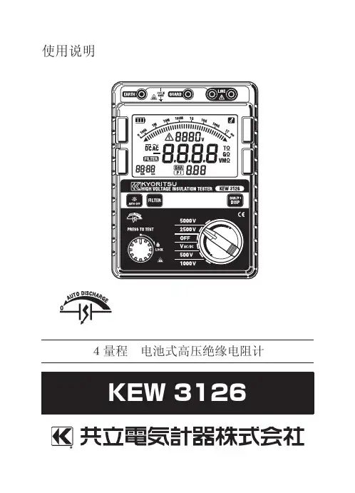
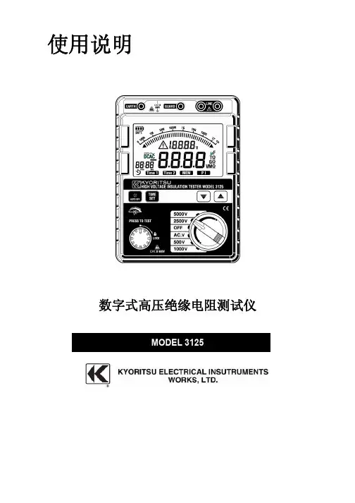
使用说明绝缘/导通测试仪MODEL 3132A目录1. 安全警告2. 特性3. 性能规格4. 仪表布局5. 测量准备5.1 零调整5.2 检查电池电压5.3 连接测试探棒5.4 检查测试探棒6. 测量6.1 交流电压警告功能6.2 测量绝缘电阻6.3 导通测量(电阻测试)7.更换电池7.1 更换电池7.2 更换保险丝8. 附件8.1 表盖8.2 肩带与测试探棒的安装9. 清洁1. 安全警告z设计符合以下国际安全标准IEC 61010-1 CAT . III 600V污染度2IEC61010-2-31 IEC61557-1/2/4 IEC61326-1 IEC60529(IP54)说明书中包括警告和安全规则,用户必须严格遵守以确保操作安全。
因此,使用前,务必通读操作指示。
警告●使用前,通读并理解说明书中的操作指示。
●请随身保存说明书以确保可随时参阅。
●必须由专业工程师严格按说明书中内容操作,任何错误操作造成的人身事故或仪器受损,共立(KYORITSU)公司概不负责。
●理解并遵守这本说明书中的安全操作说明。
必须遵守上述操作说明,如不遵守,测量时可能会导致人身伤害和仪表的毁坏。
仪表上标志,提醒用户在安全操作时,必须参阅说明书中的相关操作说明。
请务必阅读说明书中标志后的操作说明。
危险:表示操作不当导致严重或致命的伤害可能性很高。
警告:表示操作不当可能会导致严重或致命的伤害。
小心:表示操作不当可能会导致人身伤害或仪表的毁坏。
危险●请勿在通电回路中使用。
●请勿在可燃性气体的环境里进行测量,否则,可能会产生火花引起爆炸。
●测量时请握在测试线保护栏后。
●仪器表面或手潮湿时请勿测量。
●测量时不要打开电池盖。
警告●非正常情况下不要进行测量,例如:机体损坏,仪器或测试线金属部件的裸露。
●测试线连接被测设备时,请勿变更量程。
●请勿对仪器进行更换部件或改造。
如果仪器损坏,返回共力(KYORITSU)公司或经销商处检修。
●仪器潮湿时,不要换电池。
中文使用说明书5406A数字式漏电开关RCD(ELCB)测试仪日本共立电气计器株式会社目录1.警告2.操作说明3.特点4.技术规格5.测试6.测试7.维护8.携带1.警告1.1本仪器须由受过正规训练的、合格的技术人员进行操作,并在本手册规定的条件下使用。
由于用户使用不当、或违反本手册以及安全操作规定造成的设备损坏,共立公司(Kyoritsu )将不负责任何责任。
1.2使用前请仔细阅读并领会操作指南中所规定的内容。
使用本设备时请务必遵守相关的规定。
1.3本仪器可以放心使用。
然而,任何的安全措施均无法保障由于错误使用造成的对设备或人员的损害。
对于使用者而言,如果使用中麻痹大意或缺乏必要的操作训练,可能会因为自身原因造成在使用本设备时被电击或受到其它伤害。
1.4请仔细地、完整地阅读本手册。
1.5进行测量前请仔细检查量程开关以及所有的接线。
不要直接接触裸露的导线、接头或电路中任何标有“有电”(LIVE)的部分。
2.特性2.1 测试直流(DC)Sensitive断路器。
*2.2 本设备由微处理器控制,保证了最高的精度和可靠性。
2.3 触发时间数字显示。
2.4 常值电流源电路保证了主电压的波动将不会影响读数的精度。
测试电流与主电压相独立。
2.5 三个氖管用于检测连线状态。
2.6 结构紧凑、重量轻且易于使用。
2.7 弹性包装易于携带常用配件。
2.8 零点交错(Zero cross)电路保证了在0度和180度相位时进行测试。
在上述两点可以测出最小(最佳)和最大(最差)触发时间。
2.9 最大触发时间读数2000毫秒。
3.介绍3.1 5406A使用最新的微处理器技术,从而保证了产品的最佳性能及精度。
3.2 独立常值电流控制*常值电流电路保证了即使在230伏电压波动±10%的情况下仍能正确、稳定的读数。
3.3 DC Sensitive断路器*当5406A被设定为直流模式时,该仪器将测量30mA DC Sensitive断路器。