共立2056R中文使用说明书
- 格式:pdf
- 大小:401.72 KB
- 文档页数:10
IM302111/2020REV04 POWERTEC® 205C, 255C, 305CSpare Parts – POWERTEC® 205C (1)Figure A: Machine Assembly - POWERTEC® 205C (2)Figure B: Machine Assembly - POWERTEC® 205C (4)Figure C: Wire Drive Assembly - POWERTEC® 205C (5)Miscellaneous Items (not shown in figure A, B, C) - POWERTEC® 205C (5)Spare Parts – POWERTEC® 255C & 305C (6)Figure D: Machine Assembly - POWERTEC® 255C & 305C (6)Figure E: Machine Assembly - POWERTEC® 255C & 305C (9)Figure F, G: Wire Drive Assembly – POWERTEC® 255C & 305C (11)Miscellaneous Items (not shown in figure D, E, F, G) (11)Electrical Schematic (12)CODE: 50234 (12)CODE: 50235 (13)CODE: 50236, 50238, 50240 (14)CODE: 50237, 50239, 50241 (15)WEEE (16)Lincoln Electric Bester Sp. z o.o.ul. Jana III Sobieskiego 19A, 58-260 Bielawa, Polandwww.lincolnelectric.euSpare Parts – POWERTEC® 205CSP50234/50235 REV02Figure A: Machine Assembly - POWERTEC® 205CItem Description Part Number QTY 1 2 3 4 5 6 7 1 BASE R-3019-121-2/08R 1 X XWHEELS 1029-660-201R 2 X X2 REARWHEELS 1029-660-101R 2 X X3 FRONTT1 R-4034-096-1R 1 X -4 TRANSFORMERT1 R-4034-080-1R 1 - X TRANSFORMERSUPPORT R-1019-204-1/08R 1 X X5 FAN6 FAN 0873-100-031R 1 X XL1 R-4034-089-1R 1 X X7 CHOKER1 R-0010-308-1R 1 X X8 RESISTOR9 RECTIFIERV1 R-0010-309-1R 1 X X THERMAL SENSOR 80°C1115-769-003R 1 X XTHERMAL SENSOR 115°C1115-769-012R 1 X X10 REARPANEL R-1012-202-4/08R 1 X XCONNECTION) 2719-107-733R 1 X X(GAS11 STICKERSOLENOID 0972-423-005R 1 X X12 GASPLUG 1361-599-058R 1 X X13 HOLEHEIGHT) R-7040-228-3R 1 X XCYLINDER14 STICKER(GASLEAD R-5041-164-1R 1 X X15 POWER16 SHELF R-3019-123-3/08R 1 X XBUSH 1373-111-331R 2 X XCABLE17 RUBBERBUSH 1373-182-002R 3 X X18 RUBBERCABLE19 DIVIDER R-3019-201-1/08R 1 X XSTANDARD 0744-000-192R 1 X X20 REELHUBNUT B11035-1 1 X X21 PLASIC22 STICKER R-0010-276-1R 1 X XSOCKET 1158-632-032R 2 X X23 FUSECAP 1158-632-033R 2 X X24 FUSEF1 1158-660-010R 1 X X25 FUSEF2 1158-660-008R 1 X X26 FUSE27 SHIELD R-1019-197-1/08R 1 X X28 SHIELD R-1019-186-1/08R 1 X X29 STICKER R-0010-280-1R 1 X X30 KNOBS 9ET13639-3R 2 X XFigure B: Machine Assembly - POWERTEC® 205CItem Description Part Number QTY 1 2 3 4 5 6 7 RC 0874-400-011R 1 X X31 FILTER32 CLAMP 1361-599-398R 1 X X33 CABLERELEIF 1361-599-399R 1 X XT2 C-4244-374-2R 1 X X34 TRANSFORMERBOARD Y024-4R 1 X X35 P.C.36 CONTACTORK1 1115-212-207R 1 X -K1 1115-212-220R 1 - X CONTACTORX13 1131-990-005R 6 X -37 TERMINALBLOCKX13 1131-990-005R 9 - XX12,BLOCKTERMINALX11 1361-599-255R 1 - X38 TERMINALBLOCK39 PLATE D-2731-731-1R 1 - X40 STICKER(230/400V) R-0010-221-1R 1 - XPANEL R-3019-120-4/08R 1 X X41 FRONT42 SHIELD R-1019-221-1/02R 1 X XPRODUCT) R-0010-266-1R 1 X X(NAME43 STICKERSLEEVE 1361-599-708R 1 X X44 EUROPANEL) R-0010-263-1R 1 X X(FRONT45 STICKERX2,X3 C-2986-001-2R 2 X X46 SOCKETS47 STICKER 2719-107-053R 1 X XS1 1115-260-168R 1 X X48 SWITCHS3 1115-270-005R 1 X X49 SWITCHSHIELD 1115-299-073R 1 X XFLAME50 BLACKH1 0917-421-024R 1 X X51 LAMP52 POTENTIOMETERR13 1158-113-304R 3 X XR11,R12,53 KNOB 9ET10491R 1 X XS11 1115-280-005R 1 X X54 SWITCH55 SWITCHS12 1115-280-004R 1 X XSIDEPANEL R-3019-122-1/02R 1 X X56 RIGHT57 HINGLES D-2541-004-2/02R 2 X XDOOR R-1019-190-1R 1 X X58 WIREDRIVE59 LOCKS 0654-610-004R 2 X X60 LEFTPANEL R-1019-189-1R 1 X XSIDEX -1(WIRINGDIAGRAM) R-0010-264-1R61 STICKER- X1DIAGRAM) R-0010-265-1RSTICKER(WIRING62 COVER R-1012-209-2/02R 1 X X(WARNING) 2719-107-728R 1 X X63 STICKERFigure C: Wire Drive Assembly - POWERTEC 205CItem Description Part Number QTY 1 2 3 4 5 6 7 ASSEMBLY 0744-000-160R 1 X X WIREDRIVEPLATE 0744-000-219R 1 X X64 FEEDGUIDE 0744-000-224R 1 X X65 INLET66 ADAPTER 0744-000-227R 1 X X67 FIXINGCAP 0744-000-216R 1 X XCOVER 0744-000-218R 1 X X68 METAL69 PRESSURECOMPL. 0744-000-221R 1 X XARMPRESSUREARM 0744-000-220R 1 X X70 SPRINGCOMPL. 0744-000-223R 1 X XARM71 FIXING72 MOTOR 0744-000-229R 1 X XKEY 0646-231-102R 1 X X73 WOODROF74 EUROCOMPLETE R-8040-042-2R 1 X XSOCKETGUIDE R-2010-006-1R 1 X X75 OUTLET76 SLEEVES 1361-599-564R 2 X X77 SLEEVES 1361-599-565R 2 X X78 SLEEVES 1361-599-720R 2 X X79 STICKER 2719-107-732R 1 X XMiscellaneous Items (not shown in figure A, B, C) - POWERTEC® 205CItem Description Part Number QTY 1 2 3 4 5 6 7 (PRIMARY) R-5041-165-1R 1 X -80 WIRINGHARNESS(PRIMARY) R-5041-165-2R 1 - XHARNESS81 WIRING(SECONDARY) R-5041-166-1R 1 X XHARNESS82 WIRINGHARNESS R-5041-175-1R 1 X X83 WIRINGLEAD R-5041-101-1R 1 X X84 PESpare Parts – POWERTEC ® 255C & 305CSP50236/50237/50238/50239/50240/50241 REV02Figure D: Machine Assembly - POWERTEC ® 255C & 305CItem Description Part NumberQTY12345671 BASE R-3019-179-1/08R 1 X X X X X X2 REAR WHEELS 1029-660-201R 2 X X X X X X3 FRONT WHEELS 1029-660-101R 2 X X X X X X4 TRANSFORMER T1 R-4034-082-1R 1 X X - - - -TRANSFORMER T1 R-4034-083-1R 1 - - X X X X5 FAN SUPPORT R-1019-201-1/08R 1 X X - - - -FAN SUPPORT R-3019-183-1/08R 1 - - X X X X6 FAN 0873-100-031R 1 X X - - - -FAN R-8040-255-1R 1 - - X X X X7 RECTIFIER V1 R-0010-294-1R 1X X - - - -RECTIFIER V1 R-0010-295-1R 1 - - X X X X THERMAL SENSOR 80°C 1115-769-003R 1 X X X X X X THERMAL SENSOR 115°C 1115-769-012R 1 X X X X X X 8 CHOKE L1 R-4034-089-1R 1 X X X X X X THERMAL SENSOR 65°C 1115-769-053R 1 X X X X X X THERMAL SENSOR 140°C 1115-769-013R 1 X X X X X X 9 RESISTOR R1 R-0010-116-3R 1 X X X X X X 10 STICKER 2719-107-769R 1 X X X X X X 11 SHIELD R-1019-220-1/08R 1 X X X X X X 12 SHELFR-3019-181-1/08R1X X X X X X 13 RUBBER CABLE BUSH 1373-111-331R 1 X X X X X X 14 RUBBER CABLE BUSH 1373-182-002R 1 X X X X X X 15 DIVIDER R-3019-182-1/08R 1 X X X X X X 16 SHIELD R-1019-202-1/08R 1 X X X X X X 17 REEL HUB STANDARD 0744-000-192R 1 X X X X X X 18 PLASIC NUT B11035-1 1X X X X X X 19 FUSE SOCKET 1158-632-032R 2 X X X X X X 20 FUSE CAP1158-632-033R2 X X X X X X 21 FUSE F1 1158-660-010R 1 X X X X X X 22 FUSE F2 1158-660-008R 1 X X X X X X 23 STICKER F1 2719-107-193R 1 X X X X X X 24 STICKER F22719-107-111R 1 X X X X X X 25 SHIELDR-1019-186-1/08R 1 X X X X X X 26 STICKER R-0010-280-1R 1 X X X X X X 27 SHIELD R-1019-203-1/08R 1 X X X X X X 28 KNOBS9ET13639-3R 2 X X X X X X 29 SWITCH S11 1115-280-005R 1 X X X X X X 30 SWITCH S12 1115-280-004R 1 X X X X X X 31 REAR PANEL R-1019-198-1/08R 1 X X X X X X 32 BRACKETS R-1019-153-1/08R 2 X X X X X X 33 COVER R-1019-199-1/02R 1 X X X X X X 34 STICKER (WARNING) 2719-107-728R 1 X X X X X X 35 STICKER (LIFTING) R-0010-279-1R 1 X X X X X X 36 EYE BOLTS 0653-313-011R 2 X X X X X X 37 LEFT SIDE PANEL R-1019-216-1R 1 X X X X X X 38 STICKER (WIRING DIAGRAM) R-0010-298-1R 1 X - X - X - STICKER (WIRING DIAGRAM) R-0010-299-1R 1 - X - X - X 39 RIGHT SIDE PANEL R-3019-184-1/02R 1 X X X X X X 40 HINGLES D-3574-007-1/33R 2 X X X X X X 41 WIRE DRIVE DOOR R-1019-217-1R 1 X X X X X X 42 LOCKS0654-610-004R2 X X X X X XFigure E: Machine Assembly - POWERTEC ® 255C & 305CItem Description Part NumberQTY123456743 FRONT PANEL R-3019-180-1/08R 1 X X X X X X 44 STICKER (FRONT PANEL) R-0010-254-1R 1 X X X X X X 45 LAMP H1 0917-421-024R 1 X X X X X X 46 SWITCH S3 1115-270-019R 1 X X X X X X 47 BLACK FLAME SHIELD 1115-299-073R 1 X X X X X X 48 SWITCH S1 1115-260-167R 1 X X X X X X 49 SWITCH S2 1115-260-166R 1 X X X X X X 50 POTENTIOMETER R11,R12, R13 1158-113-304R 3 X X X X X X 51 KNOB 9ET10491R 1 X X X X X X 52 SHIELD R-1019-205-1/02R 1 X X X X X X53 STICKER (NAME PRODUCT) R-0010-255-1R 1 X X - - - -STICKER (NAME PRODUCT) R-0010-256-1R 1 - - X X X X 54 EURO SLEEVE 1361-599-708R 1 X X X X X X 55 SOCKETS X2, X3 C-2986-001-2R 2 X X X X X X 56 FILTER RC 0874-400-011R 1 X X X X X X 57 CABLE RELEIF R-0010-258-1R 1 X X X X X X 58 CLAMP 1361-599-633R 1 X X X X X X 59 HOLE PLUG 1361-599-058R 1 X X X X X X 60 GAS SOLENOID 0972-423-005R 1 X X X X X X 61 TRANSFORMER T2 C-4244-374-2R 1 X X X X X X 62 CONTACTOR K1 1115-212-220R 1 X - - - - - CONTACTOR K1 1115-212-219R 1 - X X - X - CONTACTOR K1 1115-212-210R 1 - - - X - X 63 P.C. BOARD Y024-4R 1 X X X X X X 64 TERMINAL BLOCK X13 1131-990-005R 6 X - X - X - TERMINAL BLOCK X12, X13 1131-990-005R 9 - X - X - X65 STICKER (230/400V) R-0010-221-1R 1 - X - X - X66 PLATE D-2731-731-1R 1 - X - X - X 67 TERMINAL BLOCK X11 1361-599-255R 1 - X - X - X 68 CAPACITOR C1 1158-121-045R 1 - - X X X X 69 POWER LEAD D-5578-171-1R 1 X - X - X - POWER LEAD D-5578-171-2R 2 - X - X - X70 WORK LEADK14011-1 1 X X - - - - WORK LEADK14012-1 1 - - X X X XFigure F, G: Wire Drive Assembly – POWERTEC ® 255C & 305CItem Description Part NumberQTY1234567 WIRE DRIVE ASSEMBLY 0744-000-160R1 X X X X - - 71 FEED PLATE 0744-000-219R 1 X X X X - - 72 INLET GUIDE 0744-000-224R 1 X X X X - - 73 ADAPTER 0744-000-227R 1 X X X X - - 74 FIXING CAP 0744-000-216R 1 X X X X - - 75 METAL COVER 0744-000-218R 1 X X X X - - 76 PRESSURE ARM COMPL. 0744-000-221R 1 X X X X - - 77 SPRING PRESSURE ARM 0744-000-220R 1 X X X X - - 78 FIXING ARM COMPL.0744-000-223R1X X X X --WIRE DRIVE ASSEMBLY 0744-000-241R 1 - - - - X X 79 FEED PLATE 0646-233-002R 1 - - - - X X 80 INTERMEDIATE GUIDE 0646-233-023R 1 - - - - X X 81 INLET GUIDE 0646-233-025R 1 - - - - X X 82 LEFT PRESSURE ARM COMPLETE 0646-233-007R 1 - - - - X X 83 RIGHT PRESSURE ARM COMPLETE 0646-233-005R 1 - - - - X X 84 FIXING ARM COMPL. 0646-233-015R 2 - - - - X X 85 SPRING PRESSURE ARM 0646-233-013R 2 - - - - X X 86 AXIS PRESSURE ARM 0646-233-003R 2 - - - - X X 87 AXES OF DRIVE ROLL 0646-233-020R 2 - - - - X X 88 GEAR WHEEL MOTOR 0646-233-028R 1 - - - - X X 89 GEAR WHEELS ROOL 0646-231-090R 2 - - - - X X 90 COVER 0646-233-027R 1 - - - - X X 91 FIXING CAPS 0744-000-190R 2 - - - - X X92 MOTOR 0744-000-229R 1 X X X X - - MOTOR 1111-722-046R 1 - - - - X X 93 WOODROF KEY 0646-231-102R 1 X X X X X X 94 EURO SOCKET COMPLETE C-2985-006-2R 1 X X X X X X 95 OUTLET GUIDE D-1829-066-4R 1 X X X X X X 96 SLEEVES 1361-599-720R4 X X X X X X 97 SLEEVES 1361-599-565R 2 X X X X - - SLEEVESD-1869-033-3R 2 - - - - X X 98 STICKER2719-107-732R1 X X X X X XMiscellaneous Items (not shown in figure D, E, F, G)Item DescriptionPart Number QTY123456799 WIRING HARNESS (PRIMARY) R-5041-176-1R 1 - X - X - X100 WIRING HARNESS (PRIMARY) R-5041-176-2R 1 X - X - X - 101 WIRING HARNESS (SECONDARY) R-5041-177-1R 1 X X X X X X 102 WIRING HARNESS R-5041-185-1R 1 - - X X X X 103 WIRING HARNESSR-5041-186-1R1 X X - - - -Electrical SchematicRecycleSTF eA lC uB r a s sB o a r d sP l a s t i c sL i q u i d C r i s t a lE x t e r n a l E l e c t r i c C a b l e sC a p a c i t o r sDescription Ref.BASE 1 X WHEELS 2, 3 X X TRANSFORMERS 4, 59 X X X SUPPORT 5 X FAN 6 X X RECTIFIER 7 X CHOKE 8 X X RESISTOR 9 XSHIELD 10, 15, 21,25, 47XSHELF 11 X RUBBER CABLE BUSH 12, 13 X DIVIDER 14 X REEL HUB 16 X FUSE SOCKET 17 X FUSE CAP 18 X FUSE 19, 20 X SIDE PANEL 26, 31, 33 XSWITCHES 22, 23, 41,42, 43X X XKNOBS 24, 46 X LOCKS 34 X HINGLES 32 X REAR PANEL 27 X BRACKETS 28 X COVER 29 X EYE BOLTS 30 X POTENCIOMETERS 39 X GAS SOLENOID 58 X X X FRONT PANEL 40 X BLACK FLAME SHIELD 44 X WIRE DRIVE ASSEMBLY 35 X X X EURO SOCKET 36 X SLEEVES 37, 38 X LAMP 45 X X EURO SLEEVE 48 X SOCKETS 49 X X X P.C. BOARD 61 X TERMINAL BLOCK 50, 52 X X PLATE 51 X CAPACITOR 53 X FILTER RC 54 X X XCABLE RELEIF55 X CLAMP56 X HOLE PLUG57 X CONTACTOR 60 X X X POWER LEAD 62 X WORK LEAD 63 X。


生物颗粒燃料熔炼炉使用维护、保养说明书Operation and Maintenance Instruction of Bio-mass Pellet FuelSmelting Furnace泰州杰利瑞节能科技发展有限公司Taizhou Jie Lirui Energy Technology Development Co., Ltd敬告!Attention!请用户使用前详细阅读产品使用维护、保养说明书,并请在使用过程中严格遵循产品使用维护、保养说明书,若由用户使用不当引起的损坏制造商将不承担责任,碳化硅石墨坩埚属易耗件,不在质保范围。
Please read the product operation and maintenance instruction carefully before use, and strictly follow the product operation and maintenance instruction during the operation. In case of any damage caused by improper use, the manufacturer will not be liable; the silicon carbide graphite crucible is subject to vulnerable part and excluded in the warranty scope.精品文档目录Catalog1 概述Introduction2 组成Components3 主要技术参数Main technical parameters4 主要用途及适用范围Main applications and applicable scopes5 配电要求Power distribution requirements6 安装Installation7 启动前检查Check before start-up8 烘炉Dry-off operation for furnace9 使用与维护Operation and maintenance10 碳化硅石墨坩埚使用注意事项Precautions for using silicon carbide graphite crucible11 常见故障与排除Common faults and troubleshooting12 运输及开箱检查Transportation and out-of-box inspection13 技术支持Technical support 1 概述Introduction生物颗粒燃料熔炼炉(以下简称“熔炼炉”)采用半气化复合燃烧技术,具有低碳环保、高效节能、操作维护简单的特点,是替代燃油炉、燃气炉、焦碳炉、电炉的最佳产品,可以降低30%~60%的能耗成本。

ELANTRA The new ELANTRAThe new ELANTRA is bold and sophisticated with even more stylish changes. Refined sportiness, exquisite interior design, and advanced safetyand convenience features create a lifestyle that's optimized for those whochallenge the future on their own terms.17" alloy wheels & tiresThin-type Full LED HeadlampQuarter Glass CoverExteriorThe new ELANTRA projects an energetic aura through the DNA of “Parametric Dynamics” and upgraded design proportions.Soft-painted InteriorPassenger side crash pad garnish and upper door trim feature premium materials.Eco-friendly Artificial Leather SeatThe seat cover creates a sustainable yet premium image.InteriorHigh-tech interior design and eco-friendly materials create a more refined and sophisticated vibe.ConvenienceAdvanced technology and a host of convenience features enhance your driving experience.Panoramic DisplayA panoramic display with a 10.25-inch full-color cluster and 10.25-inch navigation seamlessly tilted 10 degrees toward the driver allow for more stable visibility while driving.64 Color Mood LampWatch the colors change depending on your speed and driving mode. Provides 64 different colors including 10 representative colors.Wireless Smartphone ChargerSimply place your phone on the charging pad to enjoy improved charging performance.Driver’s Seat Memory SystemAutomatically adjusts your driving position by controlling the seat with one-button operation.Electric Parking Brake with Auto HoldThe parking brake can be activated or deactivated at the touch of a button, and the Auto Hold function automatically keeps the brakes engaged when stopped for added convenience.Personalized ProfileThe driving environment is automatically configured to match the user's profile upon user selection through the infotainment system screen or when unlocking the door using a digital key. Bluetooth Multi-pairingWhile driving, switch music between two smart devices connectedwirelessly.Smartstream G1.6 Gasoline Engine123Max. Power (ps/6,300rpm)15.7Max. Torque(kg·m/4,500rpm)Smartstream G2.0 Gasoline Engine149Max. Power (ps/6,200rpm)18.3Max. Torque(kg·m/4,500rpm)Gamma 1.6 MPi Gasoline Engine127.5Max. Power (ps/5,700rpm)15.77Max. Torque(kg·m/4,850rpm)PerformanceThe new ELANTRA offers excellent fuel efficiency, a quiet ride and reliable R&H performance for the ideal everyday driving experience.N Line Exclusive Lip-type Rear SpoilerN Line Exclusive 18-inch Alloy Wheels and TiresN Line Exclusive Rear BumperN Line Exclusive Front Bumper N LineThe N Line’s exclusive design adds dynamic and stylish driving to a sporty exterior.N Line Exclusive Sports Steering Wheel with Extended Paddle Shifters N Line Exclusive Leather Gear Knob N Line Exclusive Authentic Leather SeatsThe exclusive design with high-performance N DNA and the red accent offers an immersive driving experience.SafetyYou can experience the safety of higher-class models with the new ELANTRA.Blind-Spot View Monitor (BVM)Drive with confidence; our live video feature allows you to check for blind spots based on your turn signal direction,ensuring safer lane changes.Safety UnlockThe enhanced safety unlock function protects drivers from intrusion. Surround View Monitor (SVM)Maintain a bird's-eye view of your vehicle's surroundings when reversing or parking.Rear Occupant AlertAutomatically detects whether there are occupants in the rear row of the vehicle. After the ignition is turned off and thedriver's-side door is opened, an alarm sounds to reminds the driver to check the rear row for passengers.Forward Collision-Avoidance Assist (FCA)Monitors your surroundings and warns you if there is a risk of collision. After the warning, if the risk of collision increases with the target (e.g. a leading vehicle which suddenly slows down, a vehicle, a PTW, a pedestrian or a cyclist in the front), it automatically assists with emergency braking. If the risk of collision with an oncoming vehicle or a PTW increases while turning left at an intersection or if the risk of collision with an oncoming vehicle increases while driving in the lane, it automatically assists with emergency braking.Blind-Spot Collision-Avoidance Assist (BCA)Warns you if there is a risk of collision with a rear side vehicle in the blind-spot while changing lanes. After the warning, if the risk of collision increases, it automatically controls the vehicle to help avoid a collision. When forward exiting a parallel-parking spot, if there is a risk of collision with a vehicle approaching from behind, it automatically assists with emergency braking.Safe Exit Warning (SEA)When the occupant opens the door to exit the vehicle after a stop, if anapproaching vehicle from the rear is detected, the system provides a warning and helps keep the rear door closed through operation of an electronic Rear Cross-Traffic Collision Prevention Assist (RCCA)Provides a warning if there is a risk of collision with an oncoming vehicle on the left or right side while reversing. After the warning, if the risk of collision increases, it automatically assists with emergency ne Following Assist (LFA)Helps center the vehicle in its lane.Navigation-based Smart Cruise Control (NSCC)Helps drive at a safe speed on the highways and motorways using the navigation. In a safety speed zone, the speed is automatically reduced appropriately before entering the safety speed zone. Then, if leaving the safety speed zone, the speed is returned to the original setting.15" Alloy Wheel 15" Steel Wheel & Wheel Cover 16" Alloy Wheel 17" Alloy Wheel 18" Alloy Wheel(N Line)Wireless Smartphone Charger 10.25-inch Navigation Display8" Display Audio System(matt, when selecting 4.2" color LCD cluster display)USB-C type Charger (2nd Row)Parking Distance Warning (Forward/Reverse)Heated & Ventilated Seats (1st Row)Power Driver's Seat (8-way, lumbar support)Cluster (10.25-inch color LCD) Dual Full Auto Air Conditioner Exterior Sideview Mirrors(heated, power folding, LED turn signal indicators)Manual Air ConditionerCluster (4.2-inch color LCD)LED Rear Combination LampsThin-type Full LED Headlamps Bulb Rear Combination Lamp Full LED Headlamps (MFR type)Features2122Atlas White(SAW)Interior colorsExterior colorsUnit : mm, Wheel tread is based on 15" tires, and the number in parenthesis is based on 17" tires.1,593 (1,579)1,825Wheel Tread Overall Width1,604 (1,590)1,825Wheel TreadOverall WidthOverall Height1,4302,7204,710WheelbaseOverall LengthColorsSpecificationsAuthentic LeatherTricotWovenBlack MonotoneSage Green (with biomaterial seat covering)Modern GrayCashmere BeigeMedium GrayN Line Black Monotone(with Red Stitching)● The above values are results from internal testing and are subject to change after validation.● Some of the equipment illustrated or described in this catalog may not be supplied as standard equipment and may be available at extra cost.● Hyundai Motor Company reserves the right to change specifications and equipment without prior notice.● The color plates shown may vary slightly from the actual colors due to the limitations of the printing process.● Please consult your dealer for full information and availability on colors and trims.2324。

205-TC2,G,C8,BL205-TF1,R,C0,BL205-AV4,R,C3205-AV3,R,C0205-EA1,R,C0 205-PV4,R,C8205-PV5,R,C0Compact Panel Meters with full size LED’sSPECIFICATIONS - TEMPERATUREAccuracy, Thermocouple: 1° models:±1.5°C (±2.7°F) +1 count; 0.1° models: ±1°C (±1.8°F) +1 countAccuracy, RTD: 1° models: ±0.3°C(±0.5°F) +0.2% rdg; 0.1° models: ±0.1°C (±0.2°F) +0.2% rdg; ±1.5°C (±2.7°F) max errorAnalog Output: 1 non-isolated, 1 mV per degree for 1° resolution units, 10 mV per degree for 0.1° resolution units Read Rate: 2.5/sec Response Time: 1 secConstantan Chromel- Alumel Constantan Chromel- Display�Options: To order with green display, change R to G in model number, no additional cost; Power�Options: for non-isolated 9-26 Vdc, change C0 to C2A in model number, no additional cost.Ordering Example: 205-KC1-R-C0, type K meter, with -105 to 1372°C range, 1°C resolution, red display, 115 Vac; 205-FSP,R,C0, Customer-specified zero and span. Specify min input, min reading; max input, max reading.Example: 4-20 mA = 50.0-150.0. Specify decimal point position for display; 205-FSE,R,C0, Customer-specified zero, span and excitation output.Specify min input, min reading; max input, max reading; and excitation output (10 or 24 Vdc) Example: 4-20 mA = 50.0-150.0; excitation = 24 Vdc. Specify decimal point position for display.LARGE DISPLAY, SMALL CASEThe NEWPORT® 205 provides afull-size 14.2 mm (0.56”), red or green LED display, yet is housed in a minia-ture case with a 24 x 72 mm (0.94 x 2.83”) bezel. The case fits into a standard 3/64 DIN cutout, 22.2 x 68 mm (0.87 x 2.68”) and requires a depth of less than 120 mm (4.72”) behind the panel,including plug-in screw-clamp connectors (standard).EASY TO SCALEThe 205 may be shipped fully calibrated to meet a customer’s specific requirements (205-FSE). Five signal ranges can be selected via push-on jumpers and precision potentiometers which are readily accessible behind the lens to provide zero and span adjustments of 2000 counts each. Accuracy is 99.9% of reading.MULTIPLE AC POWER OPTIONS The 205-E incorporates a power supply, which is available for 24, 100, 115, or 230 Vac power. All power options provide EMI filtering, so that power line noise does not affect the reading.SPECIFICATIONS - PROCESSAccuracy at 25°C Maximum Error: ±0.05% of reading ±1 countCOMMON SPECIFICATIONSDisplay: 31⁄2 digit LED,14.2 mm (0.56”) digitsPower Consumption: 2 wattsOperating Temperature: 0 to 60°C (32 to 140°F)Dimensions: 24 H x 72 W x 120 mm D (0.94 H x 2.83 W x 4.72” D)Panel Cutout: 3⁄64 DIN 22.2 x 63 mm (0.87 x 2.68”)Weight: 200 g (7 oz)U Full-size 14.2 mm (0.56”) LED Display U 3 1/2” Digit DisplayU Analog Output Standard3/64 DIN Meter205-TC2,G,C8,BL205-TF1,R,C0,BL205-AV4,R,C3205-AV3,R,C0205-EA1,R,C0 205-PV4,R,C8205-PV5,R,C0。
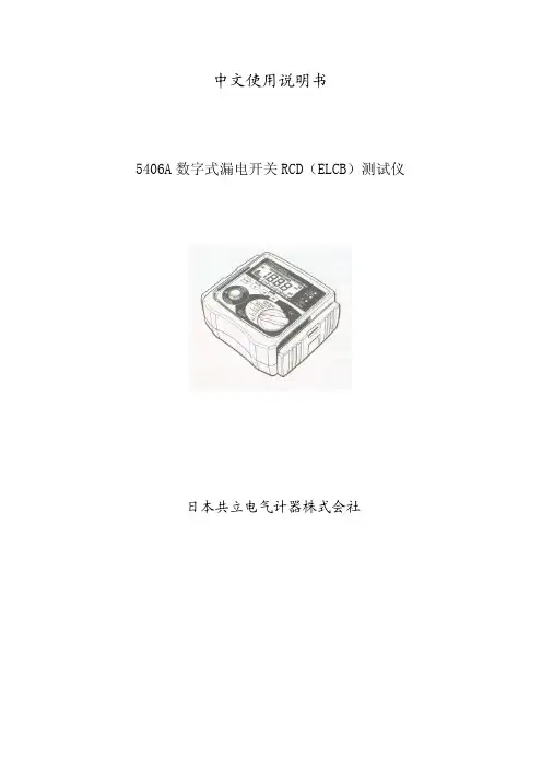
中文使用说明书5406A数字式漏电开关RCD(ELCB)测试仪日本共立电气计器株式会社目录1.警告2.操作说明3.特点4.技术规格5.测试6.测试7.维护8.携带1.警告1.1本仪器须由受过正规训练的、合格的技术人员进行操作,并在本手册规定的条件下使用。
由于用户使用不当、或违反本手册以及安全操作规定造成的设备损坏,共立公司(Kyoritsu )将不负责任何责任。
1.2使用前请仔细阅读并领会操作指南中所规定的内容。
使用本设备时请务必遵守相关的规定。
1.3本仪器可以放心使用。
然而,任何的安全措施均无法保障由于错误使用造成的对设备或人员的损害。
对于使用者而言,如果使用中麻痹大意或缺乏必要的操作训练,可能会因为自身原因造成在使用本设备时被电击或受到其它伤害。
1.4请仔细地、完整地阅读本手册。
1.5进行测量前请仔细检查量程开关以及所有的接线。
不要直接接触裸露的导线、接头或电路中任何标有“有电”(LIVE)的部分。
2.特性2.1 测试直流(DC)Sensitive断路器。
*2.2 本设备由微处理器控制,保证了最高的精度和可靠性。
2.3 触发时间数字显示。
2.4 常值电流源电路保证了主电压的波动将不会影响读数的精度。
测试电流与主电压相独立。
2.5 三个氖管用于检测连线状态。
2.6 结构紧凑、重量轻且易于使用。
2.7 弹性包装易于携带常用配件。
2.8 零点交错(Zero cross)电路保证了在0度和180度相位时进行测试。
在上述两点可以测出最小(最佳)和最大(最差)触发时间。
2.9 最大触发时间读数2000毫秒。
3.介绍3.1 5406A使用最新的微处理器技术,从而保证了产品的最佳性能及精度。
3.2 独立常值电流控制*常值电流电路保证了即使在230伏电压波动±10%的情况下仍能正确、稳定的读数。
3.3 DC Sensitive断路器*当5406A被设定为直流模式时,该仪器将测量30mA DC Sensitive断路器。
HITACHI CHEMICAL DATA SHEET Hitachi Anisotropic Conductive FilmANISOLM®AC-2056华南地区代理商 www.szretion.comPage 1. Standard Specification, Bonding and Storage Conditions, Reparability, and Characteristics (1)2. Precautions in Bonding (2)3. Connection Reliability (3)4. Effect of Bonding Temperature on Connection Reliability (4)5. Peel Strength (5)6. Insulation Reliability (6)7. Reaction Rate (6)8. Physical Properties (7)07/03/01R & D Dept.Goshomiya WorksHitachi Chemical Co., Ltd.. Standard Specification, Bonding and Storage Conditions, Repairability, and CharacteristicsItem Unit AC-2056RemarkLine m pcs 100Spacing Resolution m /mm 100 5Thickness m35,45Width mm 1.5,2.0,2.5 Length m 50,100 ColorTransparent(gray)Core mm 18.5 Temperature 80•10 ANISOLM’s ultimate temperature Pressure MPa 1 Time s5Temperature 170•10ANISOLM’s ultimate temperature Pressure MPa 2Times 20Packed •6 months after date of manufacture when stored at -10 to 5•.Unpacked • 1 month at 25• or below and 70%RH or below.Pre-bonded •2 months at -10 to 5•.1 month at 25• or below and 70%RH or below.RepairabilityRepairable By acetone or tolueneConnection resistance 1 PWB / TCP; bonding width, 2.0mmInsulation resistance1012Space 100ƒm; bonding width,2.5mmPeel strength(20•) kN/m 1.2PWB / TCP hot-bondedTack strength(20•)kN/m 0.08PWB / TCP cold-bonded Operating Temperature -40 to 100 Under no stress range Current A/mm 2 1 or belowVoltageV50 or belowSmallest connection circuit S t a n d a r d s p e c i f i c a t i o nT e m p o r a r y b o n d i n gB o n d i n g c o n d i t i o n s F i n a lb o n d i n g S t o r a g ec o nd i t i o n sS h e l f l i f eC h a r a c t e r i s t i c sNotes:1)Take ANISOLM out of the refrigerator or other storage without taking it out of its hermetic containers. Leave the ANISOLM in the containers at room temperature for about an hour. Then make sure that it does not risk condensation before using it. 2) C onnection resistance: The table indicates a half of the resistance between neighboring circuits. Current measured: 1mA. Includes the circuit resistances of the TCP and PWB.3)Tack strength: Pre-bond an ANISOLM sample to an PWB, peel its separator off, then tack TCP to it at room temperature. Then measure the tack strength of this sample. 4) O perating range: As per reliability tests using Hitachi’s test pieces.(This range varies according to the material used and external stress applied. Check the reliability of specific pieces.)The values given above represent typical measurements, not guaranteed ones.. Precautions in BondingQHead temperature: 285• TCP: Pl, 75ƒm; Cu, 35ƒm; Sn plating PWB:FR-4, 1.0mm t Ratio of temperature reached 5 seconds later: 90% or more of the ultimate temperature(•)Q .‚Q . Measuring ANISOLM temperature t ) t ) TCPQ .‚R . Heat/Pressure Head(1) Adjust carefully the eveness and parallelism of the heating head to keep the equal pressure. (2) Use a head slightly wider than the ANISOLM piece to be connected.-Example: ANISOLM width, 2.5mm• head width, 3.0mm(3) Tip the head with a thin and hard cushion, not a soft and thick one. Silicon rubber(about 0.2 mm thick with a hardness of 70 degrees or above) may be used for example. The use of too soft a cushion or excessive pressure in connection will drive adhesive in the space toward the end, resulting in insufficient adhesion. Be particularly careful when the space is wider than the circuits.Q .‚S . Misalignment of Opposite Circuits (1) Align opposite circuits well. Do not let them get misaligned.(2) In designing TCPs(FPCs), allow for the misalignment of opposite circuits due to their expansion during connection.(3) Keep the circuit misalignment at or less than the circuit width.. Connection Reliability -Connection circuitsTCP: Pl, 75ƒm; Cu, 35ƒm; Sn plating; pitch, 200ƒ PWB: Cu 35ƒm Au plating; pitch, 200ƒ -Bonding conditions; 160,170,180•2MPa•20s; ANISOLM width 2.0mmR .‚P . Changes in connection resistance in a thermal shock test(-40•, 30min•room temperature, 5min•100•, 30min•jCyclesC o n n e c t i o n r e s i s t a n c e ()0.1 0.2 0.3 0.4 0.50 200 400 600 800 1000 1200R .‚Q . Changes in connection resistance in a high-temperature, high-humidity test (85•, 85%RH)0.1 0.2 0.3 0.4 0.5 0 200 400 600 800 1000 1200Time(h)C o n n e c t i o n r e s i s t a n c e ()AC-2056 connected at 160• to 180• change little in connection resistance over time, thus a stableconnection reliability is obtained.. Effect of Bonding Temperature on Connection Reliability -Connection circuitsTCP: Pl, 75ƒm; Cu, 35ƒm; Sn plating; pitch, 200ƒ PWB: Cu 35ƒm Au plating; pitch, 200ƒ -Bonding conditions; 170•2MPa•20s; ANISOLM width 2.0mm S .‚P . Changes in connection resistance in a high-temperature test (100•)00.10.20.30.40.502004006008001000Time(h)C o n n e c t i o n r e s i s t a n c e ()S .‚Q . Changes in connection resistance in a low-temperature test (-40•)00.10.20.30.40.502004006008001000Time(h)C o n n e c t i o n r e s i s t a n c e ()S .‚R . Changes in connection resistance in a PCT test (121•-100%RH)00.10.20.30.40.5050100150200Time(h)C o n n e c t i o n r e s i s t a n c e i j.‚S . Changes in connection resistance in a moisture absorption and freeze test (-30•70•-95%RH)00.10.20.30.40.50102030405060CyclesC o n n e c t i o n r e s i s t a n c e ()AC-2056 changes little in connection resistance over time in various tests, thus a stable connection reliability is obtained.T . Peel Strength-Connection circuitsTCP: Pl, 75ƒm; Cu, 35ƒm; Sn plating; pitch, 200ƒ PWB: Cu 35ƒm Au plating; pitch, 200ƒ -Connection conditions170•A 2MPa•A 20s ANISOLM width 2.0mm Changes in peel strength in a high-temperature, high-humidity test (85•, 85%RH)Our high-temperature,high-humidity test indicated a considerably small decline in the adhesive strength of samples,thus showing the high stability of our product.. Insulation Reliability -Connection circuitsPWB: Pl, 75ƒm; Cu, 35ƒm; Au plating;comb-like pattern pitch, 50ƒ (Line/Spacing: 25ƒm / 25ƒm)TCP: Pl, 75ƒm; Cu, 35ƒm; Sn plating; pitch, 200ƒ -Measuring methodMeasure the resistance of samples with the condition to 100V DC for 60 seconds. Insulation resistance=measured resistance 100 circuits Measurement condition : 23• and 65%RH Reliability test conditions•F High-temperature, high-humidity test (85•, 85%RH)V . Reaction Rate-measuring:Each specimen was heated and hardened in oil kept at a specified temperature for 20 seconds,the amount of heat generated was measured with a DSC unit, and the reaction rate was determined with the following formula; Reaction rate = (Q 0-Q T )/Q 0100Q 0F initial amount of heat generatedQ T F amount of heat generated after hardening10 20 30 40 50 60 70 80 90 100 100 110 120 130140150160170180190 200Final ANI S OLM temperat ureR e r a t i o nW.Physical PropertiesElastic modules(Gpa) tanƒ maxANISOLM40•(•)AC-2056 1.2 125-Measuring conditionsDVE: hardened specimens (200•,2min); tensile modeFrequency, 10Hz; programming rate, 10•/min.tanƒis the temperature at which the elastic modules begins to go down and is thetemperature at which softening after hardeningChecking Connection Status。
▸▸Unprecedented power density –▸Total▸output▸of▸8800▸W▸(2▸ohms)▸in▸2U▸▸▸Four channels –▸All▸channels▸bridgeable▸for▸2-▸or▸3-channel▸configurations▸▸Lo-Z or Hi-Z (70 V / 100 V) –▸Selectable▸per▸channel,▸normal▸or▸bridged▸▸Patented Class TD® amplifier topology▸▸Voltage Peak Limiter (VPL) –▸Configurable▸per▸channel▸to▸optimize▸each▸output▸for▸connected▸loads ▸▸Phoenix-type input connectors▸▸Screw terminal output connectors▸▸Comprehensive protection and warning –▸Excessive▸output▸current,▸DC,▸high▸temperature,▸very▸high▸frequency▸(VHF),▸short▸circuit,▸open▸load,▸mains▸fuse▸protection,▸and▸soft▸start▸▸Efficient and uniform Intercooler® cooling▸▸NomadLink® network readyAn Installation Amplifier without CompromiseInstalled▸or▸on▸tour,▸uncompromising▸quality▸begins▸with▸supe-rior▸sound.▸Over▸the▸past▸decade,▸the▸sound▸of▸Lab.gruppen▸ampli-▸fiers▸has▸earned▸praise▸from▸renowned▸FOH▸engineers▸and▸owners▸▸of▸the▸world’s▸premier▸sound▸rental▸companies.▸At▸the▸core▸of▸▸the▸C▸Series▸high-power*▸model’s▸tight▸and▸transparent▸sound▸is▸patented▸Class▸TD▸technology.▸As▸a▸proprietary▸implementation▸of▸tracking▸Class▸D,▸Class▸TD▸approaches▸the▸exceptional▸efficiency▸of▸Class▸D▸while▸retaining▸the▸superior▸sonic▸quality▸of▸the▸best▸Class▸B▸output▸stages.▸A▸Regulated▸Switch▸Mode▸Power▸Supply™▸(R.SMPS)▸contributes▸to▸the▸remarkable▸efficiency▸of▸the▸C▸Series▸high-power▸models,▸while▸at▸the▸same▸time▸providing▸stable▸operation▸even▸with▸wide▸fluctuations▸in▸mains▸voltage.▸R.SMPS▸also▸works▸in▸conjunction▸with▸Class▸TD▸to▸give▸extraordinary▸power▸density.▸More▸channels▸with▸more▸power▸are▸condensed▸into▸a▸smaller▸package,▸allowing▸C▸Series▸amplifiers▸to▸minimize▸rack▸space▸requirements▸and▸reduce▸installation▸costs. Extreme▸power▸density▸demands▸efficient▸cooling,▸and▸here▸▸Lab.gruppen’s▸Intercooler▸proves▸remarkably▸effective.▸Thousands▸of▸small▸copper▸cooling▸fins▸dissipate▸heat,▸and▸all▸output▸devices▸are▸mounted▸on▸one▸row▸perpendicular▸to▸airflow▸for▸uniform▸cooling.C▸Series▸amplifiers▸are▸uniquely▸capable▸of▸adapting▸to▸a▸wide▸variety▸of▸demanding▸load▸conditions.▸Each▸channel▸has▸an▸▸individually▸configurable▸Voltage▸Peak▸Limiter▸(VPL),▸which▸allows▸the▸output▸to▸be▸optimized▸for▸any▸loudspeaker▸load▸–▸whether▸one▸massive▸subwoofer▸or▸a▸series▸of▸small▸100▸V▸loudspeakers.▸VPL▸works▸in▸combination▸with▸adjustable▸input▸gain▸to▸achieve▸maximum▸headroom▸regardless▸of▸input▸levels▸or▸output▸impedances.To▸assure▸reliability,▸and▸minimize▸service▸interruptions,▸C▸Series▸amplifiers▸offer▸comprehensive▸warning▸and▸protection▸features.▸Whenever▸faulty▸wiring,▸improper▸use,▸or▸extreme▸ambient▸tempera-tures▸threaten▸trouble,▸a▸C▸Series▸amplifier▸gives▸clear▸and▸accurate▸warning▸indications.▸Protection▸measures▸are▸inserted▸only▸when▸dangerous▸thresholds▸are▸passed.▸Conditions▸are▸re-checked▸at▸six-second▸intervals,▸and▸normal▸operation▸resumes▸when▸measure-ments▸return▸to▸nominal.Every▸C▸Series▸amplifier▸is▸ready▸for▸the▸NomadLink▸network▸right▸out▸of▸the▸box.▸With▸NomadLink,▸key▸amplifier▸parameters▸are▸displayed▸via▸DeviceControl▸software,▸and▸remote▸control▸of▸channel▸mutes▸and▸power▸on/off▸is▸under▸network▸control.▸(NomadLink▸requires▸the▸separate▸NLB▸60E▸NomadLink▸Bridge▸&▸Network▸Controller.)•Auditoriums•Performing Arts Centers•Convention Centers•Stadiums and Arenas•Theme Parks•Hotels•Houses of Worship•Restaurants•Clubs•Educational Establishments•Boardrooms•Museums•Offices•Shopping Malls•Transportation Facilities Applications*▸C▸Series▸high-power▸models▸are:▸▸▸C▸88:4,▸C▸68:4,▸C▸48:4,▸C▸24:4▸and▸C▸16:4 C 88:4L a b .g r u p p e n a b ▸ S w e d e ni n t e r n a t i o n a L c o n t a c t ▸ i n f o @L a b g r u p p e n .c o m | u S & c a n a d a c o n t a c t ▸ i n f o @t c g -a m e r i c a S .c o mw w w .l a b g r u p p e n .c o mItem no. TDS-C884_V3GeneralNumber▸of▸channels4Peak▸total▸output▸all▸channels▸driven 8800▸W Peak▸output▸voltage▸per▸channel 141▸VMax.▸output▸current▸per▸channel 35.5▸Arms Max. Output Power 16 ohms 8 ohms 4 ohms 2 ohms 70 Vrms/100 Vrms peak Per▸ch.▸(all▸ch.’s▸driven)625▸W 1250▸W 2100▸W 2200▸W 2200▸W Bridged▸per▸ch.2500▸W4200▸W4600▸Wn.r▸4)n.r▸4)Performance with Gain: 35 dB and VPL: 141 V THD▸20▸Hz▸-▸20▸kHz▸for▸1▸W<0.1%THD▸at▸1▸kHz▸and▸1▸dB▸below▸clipping <0.05%Signal▸To▸Noise▸Ratio>112▸dBA Channel▸separation▸(Crosstalk)▸at▸1▸kHz>70▸dBFrequency▸response▸(1▸W▸into▸8▸ohms)▸+0/-3▸dB 6.8▸Hz▸-▸34▸kHz Input▸impedance20▸kOhm Input▸Common▸Mode▸Rejection,▸CMR 50▸dB Output▸impedance▸@▸100▸Hz30▸mOhmVoltage Peak Limiter (VPL), max. peak output VPL,▸selectable▸per▸ch.▸3)141,▸118,▸100,▸85,▸71,▸59,▸50,▸42▸VVPL,▸when▸bridged▸3)▸1)282,▸236,▸200,▸170,▸142,▸118,▸100,▸84▸V Voltage▸Peak▸Limiter▸mode▸(per▸ch.)Hard▸/▸SoftGain and LevelAmplifier▸gain▸selectable▸(all▸channels)▸1)▸–▸rear-panel▸switches 23,▸26,▸29,▸32,▸35,▸38,▸41,▸44▸dBDefault▸gain35▸dBLevel▸adjustment▸(per▸ch.)Front-panel▸potentiometer,▸21▸position▸detented▸from▸-inf▸to▸0▸dB,▸hidden▸behind▸security▸panel/dust▸filter▸grilleConnectors and switches Input▸connectors▸(per▸ch.)3-pin▸Phoenix,▸electronically▸balanced Output▸connectors▸(per▸ch.)Barrier▸strip▸2-pole▸screw▸terminalsOutput▸bridge▸mode A+B▸and/or▸C+D,▸inputs▸A▸and▸C▸are▸input▸source NomadLink▸network On▸board,▸2▸x▸RJ45▸connectorsIntelligent▸fans▸(on/off)Y es,▸depending▸on▸presence▸of▸output▸signal Power▸on/off▸and▸Remote▸enable▸on/off Individual▸switches▸on▸front-panelCoolingTwo▸fans,▸front-to-rear▸airflow,▸temperature▸controlled▸speedFront-panel indicators Common NomadLink ▸▸Network;▸Power▸Average▸Limiter▸(PAL)▸2);▸Power▸on▸Per▸channelSignal▸present▸/▸High-impedance;▸-10▸dB▸and▸-4▸dB▸output▸signal;▸Voltage▸Peak▸Limiter▸(VPL);▸Current▸Peak▸Limiter▸(CPL);▸Very▸High▸Frequency▸(VHF);▸High▸Temperature;▸Fault;▸MutePowerOperating▸voltage,▸230▸V▸/▸115▸V▸nominal 130▸-265▸/▸65-135▸V▸5)Minimum▸power-up▸voltage,▸230▸V▸/▸115▸V 171▸V▸/▸85▸V Power▸Average▸Limiter▸(PAL)▸2)YesSoft▸start▸/▸Inrush▸Current▸Draw Yes▸/▸max.▸5▸AMains▸connector 230▸V▸CE:▸16▸A,▸CEE7;▸115▸V▸ETL:▸30▸A▸Twist▸Lock Dimensions (W/H/D)W:▸483▸mm▸(19”),▸H:▸88▸mm▸(2▸U),▸D:▸343▸mm▸(13.5”)Weight 12▸kg▸(26.4▸lbs.)FinishBlack▸painted▸steel▸chassis▸with▸gray▸painted▸steel▸front ApprovalsCE,▸ANSI/UL▸60065▸(ETL),▸CSA▸C22.2▸NO.▸60065,▸FCC▸▸Note 1):▸Automatic▸-6▸dB▸gain▸compensation▸when▸bridging▸channels.▸Ch.’s▸A+B▸and/or▸C+D,▸can▸be▸bridged▸individually.▸Note 2):▸PAL▸can▸reduce▸the▸maximum▸output▸power▸to▸keep▸the▸power▸supply▸operating▸safely,▸and/or▸to▸prevent▸excessive▸current▸draw▸tripping▸the▸mains▸breaker.▸▸▸▸▸▸▸Refer▸to▸Operation▸Manual.▸Note 3):▸For▸sine▸waves,▸peak▸voltage▸output▸values▸translate▸to▸Vrms▸with▸the▸formula▸V/1.41▸=▸Vrms.▸E.g.▸100▸V▸peak▸equals▸app.▸70▸Vrms.▸▸▸▸Hence,▸outputs▸can▸be▸set▸for▸high-impedance▸loads▸without▸requiring▸a▸transformer.Note 4):▸Regarding▸n.r.▸(not▸recommended)▸notes:▸The▸amplifier▸will▸be▸fully▸operational▸in▸bridge-mode▸into▸2▸ohm▸and▸high▸impedance▸(Hi-Z)▸loads,▸but▸due▸to▸physical▸constraints▸▸▸▸▸▸in▸the▸construction,▸the▸max.▸output▸power▸will▸not▸be▸significanty▸higher▸than▸running▸individual▸channels▸and▸therefore▸this▸mode▸of▸operation▸is▸not▸recommended.Note 5):▸Separate▸230▸V▸or▸115▸V▸versions▸available.▸Not▸selectable▸on▸the▸amplifier.All specifications are subject to change without notice.Specifications C 88:4。
MODEL5600/5601 使用说明书1. 产品种类品名 型号内容MODEL 5600MODEL 5600本体 单4电池4节, 反射胶带10个 手携式转速计MODEL 5601(8点存储,显示单位切换)MODEL 5600本体 单4电池4节, 反射胶带10个接触测定用适配器MODEL 8089(5600和5601均可使用)适配器本体橡胶接触头3个 周速轮(外周1/10m )延长光电探棒MODEL 8090(5600和5601均可使用)延长光电探棒 (φ21 导线最长1m )2. 各部件名称橡胶接触头 延长光电探棒单位显示 反射光检测显示延长光电探棒用接口内部电池盒的滑动开关切换后可使用延长探棒测试线3. 使用前准备3.1 电池安装1.用手指按住转速计背面电池盖的部分向下移动,打开电池盖。
2.仪器电池盒内部的滑动开关可设置ON(仅仪器本体、本体+适配器使用时)或OFF(延长光电探棒使用时)。
3.将电池(单4)4节按正确位置放入。
4.将电池盖盖上并安装。
3.2 反射胶带的安装——使用非接触式时将标配的反射胶带剪下1~3米长度,撕下胶带背面的牛皮纸,将其贴在被测旋转体上。
z请先擦拭贴胶带处的油污和脏物。
z请尽量将胶带贴在最靠近旋转体外周的地方。
3.3 接触式适配器的安装——使用接触式时将转速计背面的锁定螺丝拧松,接触测定用适配器从仪器上方插入后使用螺丝刀将螺丝固定。
没有螺丝刀时可借助硬币拧紧。
请确保适配器在使用中不会松动。
3.4 延长光电探棒的安装仪器电池盒中的滑动开关设置为OFF后将延长光电探棒的接头插入仪器左侧的标准接口。
4.测量4.1 使用非接触式测量时(1.)使仪器本体或延长光电探棒与所贴胶带保持5~30cm的距离,光的投射角度设定在±30°以内。
(2.)按测试开关,确认显示屏出现“”标志后读取测试值。
(3.)松开测试开关后,测试值将保留3分钟,然后切断电源。
* MODEL 5601在按键操作完成后3分钟自动切断电源。
R使用說明書Operating Instructions數位攝錄影機Digital Video CameraModel No. NV-GS150GC使用前,請仔細閱讀本說明書。
Before use, please read these instructions completely.VQT0N45-1安全注意事項ª請仔細閱讀使用說明書並正確使用攝像機。
≥由於未按照使用說明書中說明的操作步驟進行操作,而導致的損害或材料的損壞僅由用戶負責。
試用攝像機在記錄首個重要事件前,首先要試用一下攝像機,以保證其錄製性能與各種功能能夠正常使用。
製造商對於錄製內容的損失不承擔任何責任。
製造商對於因攝像機、其附件或錄影帶的故障或缺陷造成的任何損失概不負責。
請嚴格遵守版權法。
若非個人使用,複製先期錄製的錄影帶、磁碟、其他出版物或播放材料都侵犯版權法。
即使是個人使用,也嚴禁複製某些特定的材料。
≥攝像機使用了版權保護技術,並且被日本和美國的專利技術和知識產權所保護。
要想使用這些版權保護技術,必須得到Macrovision公司的授權。
禁止分解或改裝攝像機。
≥Windows是美國Microsoft公司的商標或註冊商標。
≥SD徽標是商標。
≥Leica是Leica microsystems IR GmbH公司的註冊商標,Dicomar是Leica Camera AG公司的註冊商標。
≥使用說明書中的所有其他公司和產品名稱都是各個公司的商標或註冊商標。
錄製在SD記憶卡上的檔案本攝像機可能無法回放由其他設備錄製和創建的檔案,反之亦然。
為此,請預先檢查設備的相容性。
≥讓記憶卡遠離兒童的接觸範圍,以防止兒童吞服。
參照頁參照頁頁碼的兩側標有短划線,例如:-00-菜單操作流程用>>表示。
ª警告若要防止電擊,請勿卸下機身的前蓋(或後蓋);機身沒有用戶可維修的部件。
需要維修時,請聯係授權的維修人員。
請僅使用推薦的附件。
INSULATED TYPEINSULATED TYPEINSULATED TYPE3.43.23.02.2—0.93.80.91101.281.700.047mAV T j = 25°C T j = 125°CT j = 25°C T j = 125°CV CE(sat)V EC t on t rr t c(on)t off t c(off)I CESConditionSymbol ParameterLimitsInverter IGBT part (per 1/6 module)Inverter FWDi part (per 1/6 module)Case to fin, (per 1 module) thermal grease appliedR th(j-c)Q R th(j-c)F R th(c-f)Min.THERMAL RESISTANCETyp.Max.——————Unit –I C = 25A, V IN = 0VCondition Symbol ParameterLimits Min.Typ.Max.———0.8——————Unit ELECTRICAL CHARACTERISTICS (T j = 25°C, unless otherwise noted)INVERTER PARTCollector-emitter saturation voltageFWDi forward voltageJunction to case thermalresistance (Note 3)V D = V DB = 15V V IN = 5V, I C = 25A Switching timesV CC = 600V, V D = V DB = 15VI C = 25A, T j = 125°C, V IN = 0 ↔ 5V Inductive load (upper-lower arm)Collector-emitter cut-off currentV CE = V CES2.72.52.51.50.30.62.80.6——V µs µs µs µs µs °C/W °C/W °C/WCONTROL (PROTECTION) PARTNote 4:Short circuit protection is functioning only at the low-arms. Please select the value of the external shunt resistor such that the SC trip-level is less than 1.7 times device current rating.5:Fault signal is output when the low-arms short circuit or control supply under-voltage protective functions operate. The fault output pulse-width t FO depends on the capacitance value of C FO according to the following approximate equation : C FO = 9.3 ✕ 10-6 ✕ t FO [F].SymbolI D V FOHV FOLV SC(ref)I INUV DBtUV DBrUV DtUV Drt FOV th(on)V th(off)ParameterConditionLimits Unit Circuit currentFault output voltageShort circuit trip level Supply circuit under-voltage protection Fault output pulse width ON threshold voltage OFF threshold voltage V D = V DB = 15V V IN = 5VT otal of V P1-V PC , V N1-V NCV UFB -V UFS , V VFB -V VFS , V WFB -V WFS V SC = 0V, F O circuit pull-up to 5V with 10k ΩV SC = 1V, I FO = 1mAT j = 25°C, V D = 15V (Note 4)V IN = 5VTrip level Reset levelTrip level Reset levelC FO = 22nF(Note 5)Applied between U P , V P , W P -V PC , U N , V N , W N -V NC————4.9—0.430.710.010.510.310.81.62.00.8——————0.481.5————2.43.01.43.701.303.501.30—1.100.532.012.012.512.513.0—4.22.0Min.T yp.Max.mA mA mA mA V V V mA V V V V ms V VV D = V DB = 15V V IN = 0VT otal of V P1-V PC , V N1-V NCV UFB -V UFS , V VFB -V VFS , V WFB -V WFST j ≤ 125°CNote 3:Grease with good thermal conductivity and long-term endurance should be applied evenly with about +100µm~+200µm on the con-tacting surface of DIP-IPM and heat-sink.Input current Contact thermal resistanceINSULATED TYPEINSULATED TYPEINSULATED TYPEINSULATED TYPEINSULATED TYPE。