通用智能开关使用说明书
- 格式:docx
- 大小:621.51 KB
- 文档页数:5

WI-FI SMART SWITCH WFSW15OPERATION INSTRUCTIONS• Press the ON button to turn the load ON • Press the OFF button to turn the load OFFDELAYED OFFWhen the load is ON, press and hold the OFF button for 2 seconds untilthe LED indicator starts flashing for the first time. After 10 seconds, the load will turn OFF.POWER UP STATEThis feature allows the user to change the Power Up State of the Smart Switch when the power is restored after an outage. • Press and hold the OFF button until the LED flashes for the second time (5 secs) • Release the button• Single tap the OFF button to cycle between the Power Up States: OFF state (LED single blink), ON state (LED double blinks) and the LAST State (LED triple blinks)• Once the level is chosen, press and hold either the OFF or the ON button until the LED indicator starts blinking to save the value LED INDICATOR BRIGHTNESSThis feature allows the user to change the brightness of the LED indicator.There are 5 levels (OFF to Full brightness) to change the LED indicator brightness level either while the device is ON or OFF. Changing the LED indicator brightness for the ON state • Turn the load ON• Press and hold the ON button until the LED flashes for the first time (15 secs) • Release the button• Single tap the ON or the OFF button to change the LED indicator level (it will cycle between the five levels)• Once the brightness level is chosen, press and hold either the ON or the OFF button until the LED indicator starts blinking to save the value Changing the LED indicator brightness for the OFF state • Turn the load OFF• Press and hold the OFF button until the LED flashes for the third time (15 secs)• Release the button• Single tap the OFF button or the ON button to change the LED indicator level (it will cycle between the five levels)• Once the brightness level is chosen, press and hold either the OFF or the ON button until the LED indicator starts blinking to save the valueFACTORY RESETThe device can be reset which will exclude the device from its network and restore all factory defaults. • Press and hold the ON button until the LED flashes for the second time (30 secs) • Release the button• The LED will start blinking again indicating the switch is not part of the Wi-Fi networkQuick reference table for Smart Switch FunctionalityWI-FI SMART DUPLEX RECEPTACLE WFTRCR15OPERATION INSTRUCTIONS• Press the ON/OFF button to turn the load ON • Press the ON/OFF button again to turn the load OFFDELAYED OFFWhen the load is ON, press and hold the ON/OFF button for 2 seconds untilthe LED indicator starts flashing for the first time. After 10 seconds, the load will turn OFF.POWER UP STATEThis feature allows the user to change the Power Up State of the Smart Receptacle when the power is restored after an outage. • Press and hold the ON/OFF button until the LED flashes for the second time (5 secs) • Release the button• Single tap the ON/OFF button to cycle between the Power Up States: OFF state (LED single blink), ON state (LED double blinks) and the LAST state (LED triple blinks)• Once the level is chosen, press and hold the ON/OFF button until the LED indicator starts blinking and the value will be saved LED INDICATOR BRIGHTNESSThis feature allows user to change the brightness of the LED indicator.There are 5 levels (OFF to Full brightness) to change the LED indicator brightness level either while the device is ON or OFF Changing the LED indicator brightness for the ON state • Turn the load ON by pressing the ON/OFF button• Press and hold the ON/OFF button until the LED flashes for the third time (15 secs)• Release the ON/OFF button• Single tap the ON/OFF button to change the LED indicator level (it will cycle between the five levels)• Once the brightness level is chosen, press and hold the ON/OFF button until the LED indicator starts blinking and the value will be saved Changing the LED indicator brightness for the OFF state • Turn the load OFF by pressing the ON/OFF button• Press and hold the ON/OFF button until the LED flashes for the third time (15 secs) • Release the button• Single tap the ON/OFF button to change the LED indicator level (it will cycle between the five levels)• Once the brightness level is chosen, press and hold the ON/OFF button until the LED indicator starts blinking to save the valueFACTORY RESETThe device can be reset which will exclude the device from its network and restore all factory defaults • Press and hold the ON/OFF button until the LED flashes for the fourth time (30 secs) • Release the button• The LED will start blinking again indicating the receptacle is not part of the Wi-Fi networkQuick reference table for Smart Duplex Receptacle FunctionalityWI-FI SMART UNIVERSAL DIMMER WFD30OPERATION INSTRUCTIONS• Press the ON button to turn the lights ON at the previously selected level • Press the OFF button to turn the lights OFF• The bottom LED indicates that the dimmer is turned ON (Default)• Press and hold the ON button for 2 seconds for full brightnessDELAYED OFFWhen lights are ON, press and hold the OFF button for 2 seconds until the LED indicator blinks. After a 10 second delay, the lights will fade OFF.DIMMING LEVEL ADJUSTMENTFor maximum compatibility with different load types, WFD30 allows the user to set the minimum level. Also, to save on power consumption WFD30 allows the user to set the maximum level.• After restoring power and adding the device to the Wi-Fi network , press the ON button to turn on the light • Press and hold the ON button for five seconds until the dimmer LED indicators begin to cycle rapidly• Release the ON button. Dimmer will set the light to the previously saved minimum level. During initial setup, the light will set to the factory minimum default• Press either the dim or brighten buttons to change the minimum level until the light output is acceptable• Press and release the ON button once. The dimmer LEDs will start to cycle rapidly again and the dimmer light will go to previously saved maximum level• Press either the dim or brighten buttons to change the maximum level until the light output is acceptable • Press and release the ON button, the LED indicator starts blinking and the value will be savedNOTE - To restore the default min/max, repeat the steps above and adjust light levels to full min/max settings by pressing dim/brighten buttons until the light output no longer changes.NOTE - The user can ignore setting max or min by pressing the ON/OFF button without changing the dimming level.RAPID START FEATURE (DISABLED BY DEFAULT)This feature ensures that LED/CFL lights turn on when the dimmer preset level is low. With this setting enabled, the lights will momentarily be brighter than the preset level (less than one second) and then dim down to the preset level. Depending on the type of light used, this feature may not be needed.• After restoring power and adding the device to the Wi-Fi network, press the ON button to turn on the light • Press and hold the ON button for 10 seconds until the dimmer LED indicators begin to blink for the second time • Release the ON button. LED indicators will start flashing fast to indicate the state has changed NOTE - To disable/enable the RAPID START FEATURE, repeat the steps above again.Quick reference table for Smart Universal Dimmer Functionality LED Light Level Indicator Press to DIMPress to BRIGHTENON/OFF ButtonWI-FI SMART UNIVERSAL DIMMER (cont.)WFD30LED INDICATOR BRIGHTNESSThis feature allows the user to change the brightness of the LED indicator.There are 5 levels (OFF to Full brightness) to change the LED indicator brightness level either while the dimmer is ON or OFF state Changing the LED indicator brightness for the ON state• Turn the light ON• Press and hold the ON button for 15 seconds until the LED indicator flashes for the third time• Release the button• Use the ON or OFF buttons to change the LED indicator level (it will cycle between the five levels)• Once the level is chosen, press and hold the ON button until the LED indicator starts blinking to save the valueChanging the LED indicator brightness for the OFF state• Turn the light ON• Press and hold the OFF button for 15 seconds until the LED indicator flashes for the fourth time• Release the button• Use the ON or OFF buttons to change the LED indicator level (it will cycle between the five levels)• Once the level is chosen, press and hold the OFF button until the LED indicator starts blinking to save the valuePOWER UP STATE (OFF STATE BY DEFAULT)This feature allows the user to change the Power Up State of the Smart Dimmer when the power is restored after an outage.• Turn the light OFF• Press and hold the OFF button for five seconds until the LED indicator flashes for the second time• Release the button• LED will blink either at the highest level, indicating the Power Up State is ON, or in the middle level, indicating thePower Up State is the LAST state or the lowest level indicating the Power Up State is OFF• Use the On or OFF button to cycle between the three states• Once the level is chosen, press and hold the OFF button until the LED indicator starts blinking to save the valueRAMP TIME RATE (3 SECONDS BY DEFAULT)This feature is to enable/disable a 3 second ramp time when turning the device ON/OFF. When enabled (default), the dimmer will ramp the load brightness up or down over a 3 second period when turned ON or OFF respectively. When disabled, the dimmer will instantly turn ON/OFF.• Turn the light ON• Press and hold the OFF button for 10 seconds until the LED indicator blinks for the third time• Release the button• LED indicators will start flashing fast to indicate the state has changedNOTE - to change the RAMP TIME RATE, repeat the steps aboveFACTORY RESETThe device can be reset which will exclude the device from its network and restore all factory defaults.• Turn ON the dimmer• Press and hold the ON button for 30 seconds until the LED indicator blinks for the fourth time• Release the button• LED indicator will start flashing fast while it is being reset• The LED indicator will then start blinking at a normal rate indicating the dimmer is not part of a Wi-Fi network。

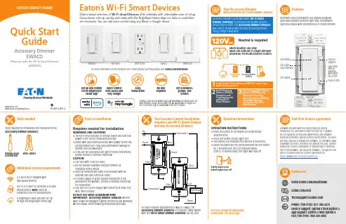
Accessory Dimmer can be wired with Wi-Fi Smart Dimmer (EWFD30) to provide multi-location ON/OFF/BRIGHT/DIM control. The Accessory Dimmer (EWACD) will need to be wired with the load controlling dimmer using a single 3-way wire.Dimmable seven step white LED display alongside push pad indicates selected light level (coordinates light level status with connected Wi-Fi Smart Dimmer)Your Accessory DimmerMust use with the Wi-Fi Smart Dimmer (EWFD30)FeaturesLight level may be adjusted with lights ON or OFF Press to brighten Press to dimTwo Location Control Installation (requires one Wi-Fi Smart Dimmer and one Accessory Dimmer)Operation instructionsMulti-location use onlyMust use with Wi-Fi Smart Dimmer (EWFD30) for multi-location controlPrior to installationOPERATION INSTRUCTIONS• Press ON button to turn lights ON at previously selected level• Press OFF button to turn lights OFF• The bottom LED indicates the dimmer is turned ON • W hen the lights are ON, press and hold the OFF button for 2 seconds until the LED indicator blinks After a 10 second delay, the lights will fade offFor color change kit installation instructions, see back pageInstall the Wi-Fi Smart Dimmer (EWFD30) using 3-way application instructions.12Install Accessory Dimmer (EWACD) through in-wall 3-way wiring with primary Wi-Fi S mart Dimmer.3Add the primary Wi-Fi Smart Dimmer (EWFD30) to the Brightlayer Home App.Accessory Dimmer (EWACD) will simply follow the commands of the Wi-Fi Smart Dimmer.3Tools neededAdditional system requirementsPhillips-head ScrewdriverWire cuttersTools required for installation (not included) for the Accessory Dimmer (EWACD):A 2.4GHz Wi-Fi network with high-speed internetIOS 12.0 or later or Android 8.0 or later mobile device. Note: Must be connected to Wi-Fi and Bluetooth A Brightlayer Home account set-up through the Brightlayer Home AppVoice controlw ith Alexa and Hey Google installation requiredSet schedules, groups, and scenesFor multi-location applications (3-way or 4-way), the Accessory Dimmer (EWACD) or a regular 3-way switch with one Wi-Fi Smart Dimmer (EWFD30) can be used.Neutral is requiredSafely leave roombefore lights turn offWi-Fi Smart Devices offer reliability with unbeatable ease o f setup. /smarthomeEWFSW15EWFTRCR15EWACDEWFFSC15Amazon, Alexa and all related logos are trademarks of , Inc. or its affiliates. Google and Google Play are trademarks of Google LLC. Wi-Fi CERTIFIED logo is a trademark of the Wi-Fi Alliance.Requires neutral for installationWARNINGS AND CAUTIONS • T urn OFF circuit breaker or remove fuse(s) and test that power is OFF before installation process • N ever wire any electrical device with power turned ON Wiring dimmer HOT may cause permanent damage to dimmer and void warranty • I f you are not sure about any part of these instructions, please contact a licensed electrician CAUTION• Use only with 120V/AC 60Hz• Do not exceed maximum rating of dimmer as indicated on the device • M ust be installed and used in accordance with all national and local electrical codes • I f a bare copper or green ground connection is not available in the wallbox, contact a licensed electrician for installation • U se only #14 or #12 copper wire rated for at least 75ºC with these devicesDO NOT USE WITH ALUMINUM WIREIMPORTANT: Accessory Dimmer (EWACD) will not work or will be damaged if wired incorrectly and warranty will be voided. Refer to wiring instructions provided.Once selected the devices would be displayed as shown below:Note: Now the user can utilize many features that are available such as creating schedules, scenes, preset light levels and minimum/maximum brightness settingsthrough the Brightlayer Home App.FCC STATEMENTThis device complies with Part 15 of the FCC Rules. Operation is subject to the following two conditions:1: This device may not cause harmful interference, and2: This device must accept any interference received, including interference that may cause undesired operation.NOTE: This equipment has been tested and found to comply with the limits for aClass B digital device, pursuant to Part 15 of the FCC Rules. These limits are designed to provide reasonable protection against harmful interference in a residentialinstallation. This equipment generates, uses and can radiate radio frequency energy and, if not installed and used in accordance with the instructions, may cause harmful interference to radio communications. However, there is no guarantee that interfer-ence will not occur in a particular installation. If this equipment does cause harmful interference to radio or television reception, which can be determined by turning the equipment off and on, the user is encouraged to try to correct the interference by one or more of the following measures:• Reorient or relocate the receiving antenna.• Increase the separation between the equipment and receiver.• Connect the equipment into an outlet on a circuit different from that to which the receiver is connected.• Consult the dealer or an experienced radio/TV technician for help.FCC CAUTION: Any changes or modifications not expressly approved by Eaton Wiring Devices could void the user’s authority to operate the equipment.This device complies with Industry Canada’s license-exempt RSSs. Operation is subject to the following two conditions:(1) This device may not cause interference; and(2) This device must accept any interference, including interference that may cause undesired operation of the device.EATON WIRING DEVICES LIMITED 2 YEAR WARRANTYEaton Wiring Devices warrants its Dimmer to be free of defects in materials and workmanship in normal use and service for a period of two years from date of original purchase. THIS TWO (2) YEAR LIMITED WARRANTY IS IN LIEU OF ALL OTHER WARRANTIES, OBLIGATIONS, OR LIABILITIES, EXPRESSED OR IMPLIED (INCLUDING ANY IMPLIED WARRANTY OF MERCHANTABILITY OR FITNESS FOR A PARTICULAR PURPOSE THAT IS IN DURATION IN EXCESS OF TWO YEARS FROM THE DATE OF ORIGINAL CONSUMER PURCHASE). NO AGENT, REPRESENTATIVE, OR EMPLOYEE OF EATON HAS AUTHORITY TO INCREASE OR ALTER THE OBLIGATIONS OF EATON UNDER THIS WARRANTY. To obtain warranty service for any properly installed Eaton Dimmer that proves defective in normal use send the defective Dimmer prepaid and insured to Quality Control Dept., Eaton Wiring Devices, 203 Cooper Circle, Peachtree City, GA 30269; in Canada: Eaton Wiring Devices, 5925 McLaughlin Road, Mississauga, Ontario L5R 1B8. Eaton will repair or replace the defective unit, at its option. Eaton will not be responsible under this warranty if examination shows that the defective condition of the unit was caused by misuse, abuse, improper installation, alteration, improper maintenance or repair of damage inTroubleshooting guideAccessory Dimmer color change kit installation instructionsSTEP 1 :Squeeze top tabs on either side of the deviceSTEP 2 :Pull faceplate offSTEP 3 :Line up all tabs and snap the faceplateWarrantyLED statusSet-up the Wi-Fi smart dimmer (EWFD30)Add the primary Wi-Fi Smart Dimmer (EWFD30) to theBrightlayer Home App, so that the Accessory Dimmer (EWACD) will simply follow the commands of the Wi-Fi Smart Dimmer.STEP 1 : Double click on the “ON” button on the Wi-Fi Smart Dimmer (EWFD30). Status LED on the Wi-Fi Smart Dimmer should be blinking cyan to indicate that the device is in set-up mode. If the status LED is not blinking, refer to the Troubleshooting guide.STEP 2 : Log in to your account on the Brightlayer Home App STEP 3 : Select “Devices” optionOnce initial device is installed, additional devices can be added using the global add (+) buttonNext click on “Add a Device” option shown in the screen belowSelect the device type to addHow to download the AppGet your Wi-Fi Smart Device running in 3 easy steps!STEP 3 (continued) :Amazon, Alexa and all related logos are trademarks of , Inc. or its affiliates. Google and Google Play are trademarks of Google LLC. Wi-Fi CERTIFIED logo is a trademark of the Wi-Fi Alliance.STEP 3 (continued) :SymptomPossible causeSolutionDevice doesn’t function. All LEDs are OFFA)B) C) Circuit breaker is OFF or trippedImproper wiring Defective dimmerA) B) C) Turn ON the circuit breakerCheck and correct wiring Replace dimmerOne of the LED indicators is blinking, but can’t control the load.Accessory dimmer (EWACD) is not connected to the Wi-Fi Smart Dimmer (EWFD30)Check wiring diagram Quick reference table for Wi-Fi Smart Dimmer (EWFD30) functionalityNOTE: Not all products include color change kits.Available in 3 different color change kitsFor more information, visit /smarthomeDownload the AppSearch and download the Brightlayer Home App via the App Store or Google Play.Select “Create an Account” to create an account by following the instructions on the screen.Fold in half vertically with page 1 on outside, then Z-fold in horizontal direction to final folded size of 3.4 in. W x 5.5 in. H with part number facing outward.。
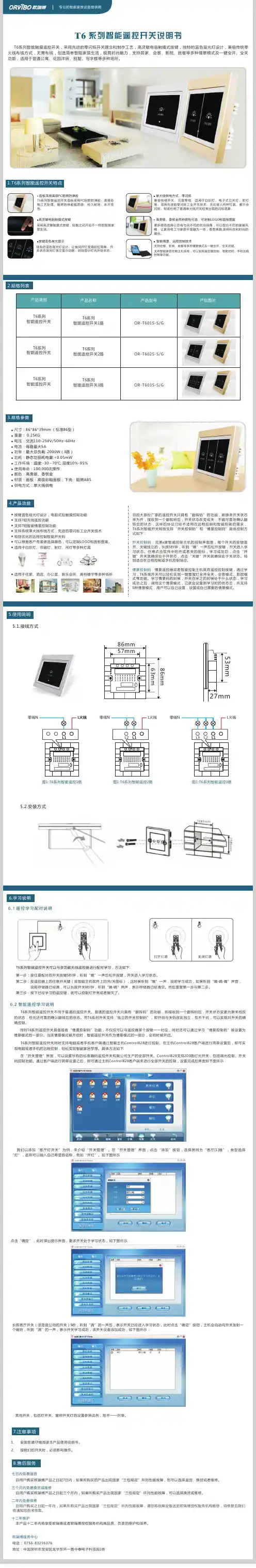
FK系列智能复合开关产品使用说明书1. 产品简介FK系列智能复合开关(简称复合开关)有共补开关(FK300)和分补开关(FK100)两种,共补开关用于投切三相电容,即三角型接法的电容;分补开关用于投切单相电容,即分别接三只单相电容的一端,三只单相电容的另一端接零线。
复合开关选用晶闸管开关和磁保持开关并联运行,其在接通和断开的瞬间具有可控硅过零投切的优点,而在正常接通期间又具有磁保持开关零功耗的优点。
复合开关具有无冲击、低功耗、高寿命等显着优点,可替代接触器或晶闸管开关,广泛用于低压无功补偿领域。
该产品通过了电力工业电力设备及仪表质量检验测试中心的检验。
2. 功能特点☆电压过零投入,电流过零切断;☆开关接通后低功耗,不用外加散热片;☆无需外接串联电抗器;☆输入信号与开关光电隔离;☆可直接与无功补偿控制器配合使用;☆内置控制电源,无需外配电源;☆具有开关状态指示灯,电容接通时,指示灯亮;☆抗干扰能力强,高EMC保护措施;3. 技术参数3.1 主电路3.2 控制电路3.3 电磁兼容3.4 工作条件①:除火灾、爆炸、水淹、强化学腐蚀等场所外的地方。
3.5 设备尺寸4.选型对照表①对分补开关而言,电容容量是指三只单相容量之和。
②分补开关有两种控制形式,分别支持控制器输出采用公共正端(Z)或公共负端(F)的方式,用户订货需指明。
③有谐波的场合,需根据实际承载电流的大小,提高所选复合开关的规格容量,否则将造成开关损坏;另外,复合开关不适用于频繁投切的场所。
5. 接线说明下图是FK系列复合开关的三种面板示意图(以20kvar开关为例):智能复合开关智能复合开关智能复合开关①A1、B1、C1对应三相系统输入;A2、B2、C2对应三相输出,接电力电容。
②N为零线,其从二次回路引入,用于对开关内部的控制电源供电。
③开关面膜上的COM端为控制电平输出的公共端,对FK100-20F而言,其为负电平;对FK100-20Z而言,其为正电平,以适应不同控制器的要求。
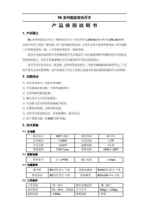
Function introductionImportant: Read All Instructions Prior to Installation •DO NOT install with power applied to device. •DO NOT expose the device to moisture.Safety & WarningsOperation•ZigBee in wall smart switch based on latest ZigBee 3.0 protocol •100-240VAC Wide Input and Output Voltage•Supports resistive loads, capacitive loads or inductive loads •1 channel output, max. load up to 4.8A•Input and Output with Screw Terminals, Safe and Reliable •Enables to control ON/OFF of connected light source•ZigBee end device that supports Touchlink commissioning•Can directly pair to a compatible ZigBee remote via Touchlink without coordinator•Supports self-forming zigbee network without coordinator and add other devices to the network •Supports find and bind mode to bind a ZigBee remote•Supports zigbee green power feature and can bind max. 20 zigbee green power remotes •Compatible with universal ZigBee gateway products•Mini Size, Easy to be Installed into a standard size wall box •Radio Frequency : 2.4GHz •Waterproof grade: IP20Input VoltageOutput VoltageOutput CurrentProduct DataSize(LxWxH)100-240VACResistive load: max. 4.8ACapacitive/Inductive load: max. 1.4A100-240VAC45.5x45x20.3mm1.Do wiring according to connection diagram correctly.Input Clusters •0x0000: Basic• 0x0003: Identify•0x0004: Groups• 0x0005: Scenes• 0x0006: On/off•0x0b04: Electrical Measurement Output Clusters •0x0019: OTAZigBee Clusters the device supports are as follows:2.This ZigBee device is a wireless receiver that communicates with a variety of ZigBee compatible systems. This receiver receives and is controlled by wireless radio signals from the compatible ZigBee system.•0x0702: Simple Metering •0x0b05: DiagnosticsMain Features:• Can operate under two-wire connection with no neutral lead or three-wire connection with neutral lead • Soft start function,• Works with various types of switches – momentary, toggle, three-way, etc.• Active element: semiconductor electronic switch,• To be installed in wall switch boxes of dimensions allowing for installation, conforming to provisions of applicable regulations,• The Bypass is an extension unit.The switch operates under the following loads:• Conventional incandescent and HV halogen light sources • ELV halogen lamps (with electronic transformers)• MLV halogen lamps (with ferromagnetic transformers)• Compact fluorescent CFL tube lamps with electronic ballast • Fluorescent tube lamps with electronic ballast• Supported light sources (power factor > 0.5) with minimal power of 3W using the Bypass (depending on the type of load)reset of the switch,short press to turn on/off load(3-wire with Neutral input)(2-wire with No Neutral output)(3-wire with Neutral output)3.Zigbee Network Pairing through Coordinator or Hub (Added to a Zigbee Network )Step 1: Remove the device from previous zigbee network if it has already been added to , otherwise pairing willfail . Please refer to the part "Factory Reset Manually ".Step 2: From your ZigBee Controller or hub interface, choose to add lighting device and enter Pairing mode as Step 4LED indicator, stays solid onwhen power on the switch, turns off after added to a zigbee hub,indicates (same status as connected load) when program the switch (network pairing, touchlink, factory reset)40160394.TouchLink to a Zigbee Remote5.Removed from a Zigbee Network through Coordinator or Hub InterfaceFrom your ZigBee controller or hubinterface, choose to delete or reset thelighting device as instructed. Theconnected light blinks 3 times to indicatesuccessful reset.Step 1: Method 1: Short press“Reset” button (or re-power on: Re-power on theStep 4:Step 2: Bring thepanel within10cm of theStep 3Note: 1) Directly TouchLink (both not added to a ZigBee network), each device can link with 1 remote.2) TouchLink after both added to a ZigBee network, each device can link with max. 30 remotes.3) For Hue Bridge & Amazon Echo Plus, add remote and device to network first then TouchLink.4) After TouchLink, the device can be controlled by the linked remotes.6.Step 2: Short press “Reset.”7.Factory Reset through a Zigbee Remote (Touch Reset)Note: Make sure the device already added to a network, the remote added to the same one or not added to anynetwork.Step 4: There shall be indicationon the remote and connected lightflashes 3 times for successfulStep 2:Bring the remote or touchpanel within 10cm of the lightingdevice.Step 3: SSet the remote or touchpanel into Touch Reset procedureto reset the device, please refer tocorresponding remote or touchpanel manual to learn how.8.Find and Bind ModeStep 2:or touch panel manualStep 3control it thenNote: Make sure the device and remote already added to the same zigbee network.9.Learning to a Zigbee Green Power RemoteStep 2:Step 3LiveNeutral11. Setup a Zigbee Network & Add Other Devices to the Network (No Coordinator Required): Short press “Reset.” 10. Delete Learning to a Zigbee Green Power RemoteStep 2: Step 3Wiring DiagramNotes for the diagrams:L - terminal for live leadN - terminal for neutral leadOut - output terminal of the switch (controlling connected light source)S1 - terminal for switch (has the option of entering the device in inclusion/exclusion mode)COM - terminal for grounding to the switch connected to the switchCompatible load types and recommended values of power for supported loads:Supported external switch types (should be configured by factory setting):1) Push switch (default factory setting)2) Normal On/Off switch (should be configured by factory setting upon request)3) 3-Way switch (should be configured by factory setting upon request)(2) 3-Wire Connection With Neutral Lead The Bypass is a device designed to work with the micro smart dimmer. It should be used in case of connecting LED bulbs or energy saving compact fluorescent lamps. The Bypass prevents flickering of the LED lights and glowing of the turned off compact fluorescent lamps. In the case of 2-wire connection, the Bypass allows to reduce minimum power of load required by the dimmer for correct operation. The Bypass provides powering of the dimmer in case of controlling the low loads of minimum power down to 3W (for cos φ>0.5).(1) 2-Wire Connection With No Neutral LeadNOTE: Switch connected to the S1 terminal activates the basic functionality of the dimmer (turning the lighton/off).Live NeutralWith PUSH LVWith PUSHLive NeutralWith PUSH LV With PUSHNOTE: Switch connected to the S1 terminal activates the basic functionality of the dimmer (turning the light on/off).(4) Multiple Momentary or Push Switches Connection (3) 3-Way Switch Connection 3-Way Switch (SPDT)3-Way Switch (SPDT)With PUSH LVLive Without AC inputLive NeutralNeutral。
本文部分内容来自网络整理,本司不为其真实性负责,如有异议或侵权请及时联系,本司将立即删除!== 本文为word格式,下载后可方便编辑和修改! ==手机app远程遥控电源智能开关说明书篇一:智能开关型电动执行器说明书VESON-Ⅱ型电动执行器控制部件使用说明一、概述VESON-Ⅱ型电动执行控制器是一种智能型、一体化的开关型电动执行器(俗称电动头)控制部件。
VESON-Ⅱ具有丰富的自诊断与保护功能,以及行程方向、电机方向自调整等功能。
带有液晶显示的就地操作面板,提供了全中文的设置菜单及简明的操作指导。
运行中液晶显示器实时显示阀门位置、工作状态、故障原因等。
控制器提供了就地与远方可切换操作功能。
远方控制可采用无源接点,通过控制台按钮手动操作。
也可由控制系统的继电器接点或集电极开路门、电平、脉冲等DO信号驱动,因此可方便地与DCS、PLC、计算机或其它的控制仪表直接连接。
VESON-Ⅱ可输出阀门全开、全关的无源接点信号。
就地操作按钮可采用非通透式磁性按钮或红外遥控,以满足更高的防护等级要求。
二、主要功能1、就地操作功能通过就地操作面板的“开”、“关”、“停”三键实现对执行器的开、关、停操作。
2、远程操作功能远程控制可接入“开”、“关”两只按扭,或与DCS、PLC等控制系统通过两路DO(集电极开路门或24V电平、脉冲、继电器等)连接,实现对执行器的开、关、停操作。
3、自动调整电机转动方向设置完成后自动调整电机方向为需要的方向。
4、自动调整行程方向用户可任意指定执行器的开、关方向,无需改变任何接线。
5、电子全开、全关限位功能。
6、卡涩保护。
自动回退、前进三次,仍卡涩断电报警。
7、位置传感器故障报警及保护。
如果位置检测电位器发生故障,引线故障或位置检测电路故障,可自动停电机并点亮报警灯。
三、主要技术指标1、工作电源: AC60V~AC280V。
2、位置传感器:0~500Ω至0~10K电位器。
3、远方开、关控制信号:无源接点、集电极开路门:灌电流10mA。
Note: QR Code used forSmartStart inclusion. DSKCode can be found onpackaging. Do not removeor damage them.Important safety information.Please re ad this and the online guide(s) at/ss7 carefully. Failure to follow therecommendations set forth by Aeotec Limited may bedangerous or cause a violation of the law. Themanufacturer, importer, distributor, and / or reseller willnot be held responsible for any loss or damageresulting from not following any instructions in thisguide or in other materials.Smart Switch 7 is intended for indoor use in drylocations only. Do not use in damp, moist, and / or wetlocations.Quick start.The following will step you through installing SmartSwitch 7 and connecting it to your Z-Wave network.1. Plug Smart Switch 7 into a power outlet; its LED willflash blue slowly.2. To connect Smart Switch 7 to your automationnetwork:a. If your Z-Wave gateway supports SmartStart,scan Smart Switch 7's QR Code using yourgateway's app. Once scanned, Smart Switch 7will join your Z-Wave network automaticallywithin 10 minutes.b. Else, set your gateway into its 'add device'mode. Refer to its manual if you are unsure ofhow to perform this step.Then press Smart Switch 7's Action Button 2xtimes within 1 second; its LED will blink toindicate pair mode.c. If your gateway supports S2 security, and youwant your device to use this higher level ofsecurity, please enter the first 5 digits of theDSK into the gateway's interface whenprompted. Refer to the gateway’s manual if youare unsure how to perform this step. Do not losethe DSK or remove it from the product orpackage.3. When Smart Switch 7 successfully joins yourZ-Wave network, its LED will become a solid bluefor 2 seconds. Should its LED still flash blue, thisindicates it was unable to join your Z-Wavenetwork; repeat the above steps and pleasecontact us for further support if needed.Smart Switch 7 is now a part of your Z-Wave homecontrol system. You can configure it and itsautomations via your Z-Wave system; please refer toyour software’s user guide for precise instructions.Get help & learn more.Should you encounter any problem with Smart Switch7, visit /ss7 or contact our supportteam via /contact. You can also learn moreabout Smart Switch 7 features, configuration options,and technical specifications at the link.Gateway compatibility.To see if this device is known to be compatible withyour Z-Wave gateway, please refer to/z-wave-gateways.Manufactured for the importer by Aeotec Limited (#704, BrightWay Tower, 33 Mong Kok Rd, Mong Kok, Hong Kong)contactable via /contact. Imported into theEuropean Union by Aeotec Group GmbH (GroßeJohannisstraße 7, Hamburg 20457, Germany). The importerand / or distributor of this device can both be reachedseparately with the company from whom you have purchasedthis device from responsible for warranty, technical support,and compliance related queries.Declaration of Conformity. Aeotec Limited declares thatZWA023 is in compliance with the essential requirements andother relevant provisions of RED 2014/53/EU, RoHS2011/65/EU, IEC 62321:2008, EN 50581:2012 and ErPDirective 2009/125/EC, No 1275/2008 AMENDMENT801/2013. The full text of the declaration is available from/ss7/docSpecifications. Specifications. Z-Wave devices operatebetween 868.40 & 926.3 MHz depending on local restrictions.It uses up to -5.68dBm ERP of transmission power, enablingwireless connectivity.Full information on device specifications and certifications at/ss7/specsDisposal guidelines and WEEE. Aeotec devices maycontain batteries; remove when not in use. Do not dispose of Used in this guide.Smart Switch 7ZWA023© & ™ Aeotec Limited. Version: 501002300001 - AA In Europe contact Aeotec Group GmbH; Große Johannisstraße7, 20457 Hamburg, Germany.Conforms to UL STD. 62368-1Certified to CSA STD. C22.2No. 62368-1FCC ID: 2AOGIZWA023device as unsorted municipal waste, use separate collection facilities. Contact your local government for further information.One-Year Limited Warranty. Aeotec Limited warrants included Aeotec branded hardware device when purchased new and delivered in new condition and in its original container against defects in materials and workmanship for one year from the date of original purchase from an authorized reseller when purchased and used in the region of original export. In line with the terms of sales between Aeotec and the authorized importer / reseller of this device, any claims against the foregoing warranty are to be handled by the authorized distributor / reseller directly. The foregoing warranty is subject to the proper installation, operation, and maintenance of the device in accordance with installation instructions and the operating manual supplied to customer and further documentation made available digitally. Liquid damage, including, but not limited to, internal liquid damage caused by improper use, closure or affixing of the hardware, is not covered by this warranty. Splash, water, and dust resistance are not permanent conditions and resistance might decrease as a result of normal wear. Not warranted for damage from open flames and heat, and exposure to sun. Not warranted for battery leak damage; always remove all batteries from products that not being used. Aeotec does not warrant against normal wear and tear, nor damage caused by accident or abuse. Please be sure to read this device’s support notes, digital materials, and quick start guide fully.Subject to the full terms of obtaining service within 30 days ofthe manifestation of a problem, if you submit a valid claimunder this warranty, Aeotec shall provide further information inobtaining warranty services from the authorized importer and /or seller of this device. The full warranty, including warrantyexclusions and liabilities, are available at/warranty Aeotec’s English languagewarranty and instructional information is paramount totranslations provided in any other language and prevails overany such translations.FCC Notice. The edition of this device made and certified forthe US market and marked as such complies with part 15 ofthe FCC rules. Operation is subject to the following twoconditions: (1) this device may not cause harmful interference,and (2) this device must accept any interference received,including interference that may cause undesired operation. Themanufacturer is not responsible for any radio or TV interferencecaused by unauthorized modifications to this equipment. Suchmodifications could void the user’s authority to operate theequipment. This equipment has been tested and found tocomply with the limits for a Class B digital device, pursuant topart 15 of the FCC Rules. These limits are designed to providereasonable protection against harmful interference in aresidential installation. This equipment generates uses and canradiate radio frequency energy and, if not installed and used inaccordance with the instructions, may cause harmfulinterference to radio communications. However, there is noguarantee that interference will not occur in a particularinstallation. If this equipment does cause harmful interferenceto radio or television reception, which can be determined byturning the equipment off and on, the user is encouraged to tryto correct the interference by one or more of the followingmeasures: (1) Reorient or relocate the receiving antenna. (2)Increase the separation between the equipment and receiver.(3) Connect the equipment into an outlet on a circuit differentfrom that to which the receiver is connected. (4) Consult thedealer or an experienced radio/TV technician for help (5)Ensure this device and its antenna(s) are not be co-located oroperating in conjunction with any other antenna or transmitter.RF Exposure Statement. The device has been evaluated tomeet FCC/CE general RF exposure requirement. The devicecan be used without restriction.California Proposition 65. WARNING: This product containsa chemical known to the State of California to cause birthdefects or other reproductive harm. Use only for intendedpurposes. Do not use for other purposes including, but notlimited to, the consumption of food and drinks.While the information in this guide has been compiled withcare, it may not be deemed an assurance of devicecharacteristics. All information, including, but not limited to,information regarding the functionality, features, and / or devicespecifications are subject to change. Aeotec Limited reservesall rights to revise or update its products or documentationwithout any obligation to notify any individual or entity. AeotecLimited shall be liable only to the degree specified in the termsof sale and delivery.。

SLFK(普通型)智能低压复合开关使用说明书目录第一章概述...................................1第二章技术参数. (2)第三章主要技术特点 (4)第四章型号命名 (5)第五章安接及接线 (7)一、概述SLFK(普通型)智能低压复合开关是新一代低压无功补偿装置中电容器的投切开关,是一种智能化的环保节能型控制执行部件,是我公司针对可控硅和交流接触器在低压无功补偿应用方面存在的先天不足而精心研制开发的最新科技成果。
本产品适用于对低压补偿电容器等的通断控制。
基本工作原理是将可控硅与磁保持继电器并接,使复合开关在接通和断开的瞬间具有可控硅过零投切的优点,而在正常接通期间磁保持继电器又具有无功耗的优点。
与交流接触器、可控硅或固态继电器等开关元件相比较SLFK(普通型)智能低压复合开关有很大的技术优势。
主要优点是接到控制信号后,通过逻辑判断,自动寻找最佳投入(切除)点;保证过零投切,无涌流;触点不烧结;能耗小;无谐波注入;同时具有电压异常保护;缺相保护;元件故障保护等功能。
与同类产品相比,在技术上具有极大的先进性,高效低耗,环保节能,尤其是在涌流和安全可靠性方面性能大大提高。
本产品是广西区经贸委及区科委下达的重点创新项目,已于2002年7月通过电力工业部无功补偿成套装置质量检验测试中心检验通过;2012年3月通过国家强制3C认证。
- 1 -二、技术参数1.工作环境条件环境温度:-25℃~+65℃;相对湿度:40℃时,20%~90%;2.额定电压、额定电流、工作电源及控制电压额定工作电压:220/380V三相四线交流50HZ;允许偏差:三相电压同步变化不大于±20%;波形为正弦波,失真度小于5%;额定频率:50HZ±5%;工作电源:380V,50HZ;额定电流:45A/55A/70A。
控制电压:直流:5~24V;交流:5~24V。
3.主要技术指标:使用寿命:50万次以上相数:三相:△型接法(3相共补)单相:Y形接法(单台3相分补) 接电容器容量:.SLFK-△380V45A≤20KvarSLFK-△380V55A≤30KvarSLFK-Y220V45A≤20KvarSLFK-Y220V55A≤30Kvar 功耗:≤1.5VA- 2 -接触压降:≤100mV接点耐压:≥1600V每次接通与关断间隔:≥1秒连续两次接通间隔:三相(△型接法)≥180秒单相(Y形接法)≥180秒(注:接通间隔如客户有实际需求可定做)输入阻抗:≥6.8K,导通阻抗:≤0.003Ω安全保护功能:1)电压故障缺相保护;2)电源电压缺相保护;3)自诊断故障保护;4)空载保护;5)停电保护。
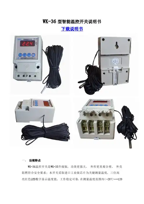
WK-36型智能温控开关说明书下载说明书一、功效特点WK-36温控开关是WK-35升级版, 功效更强大、外形更美观合理、外壳阻燃符合安全要求; 本开关采取进口工业级芯片为关键测量温度, 三位高亮红色LED数字显示温度值, 工作稳定可靠。
在测量温度范围内(-20℃--+120℃)能依据用户设定温度范围对负载进行开关控制。
用户设定温度参数存放到芯片中, 不受停电影响, 掉电不会丢失数据。
共有4种不一样温度控制模式, 既适适用于加热型控制, 也适适用于降温型控制, 能满足绝大多数应用场所需求。
正向加热适适用于电暖器、电烤炉、电孵化、电热水器, 过温保护等, 反向降温适适用于空调制冷, 排气抽风等。
提醒用户注意: 在您首次使用温控开关投入工作之前, 必需先设置好适合于您那种温控模式, 不然不能正常工作, 具体操作见[温控模式设置]章节!二、相关参数1. 额定电压: 220V/50Hz ;2. 最大负载功率: 3000W;3.测量显示温度范围: -20—120℃4.控制温度范围: -20—120℃5. 温度误差≤±0.50℃--±0.80℃6.显示分辨率:0.1℃(小于-9.9 ℃和大于99.9 ℃不显小数位);7.外壳材料: 高阻燃工程塑料8. 安装方法: 端子接线(导轨、吸壁、挂装3种固定方法) 9. 外形尺寸: 120*75*55mm10. 单个重量: 400克 ; 11. 温度传感器类型及连线长度: 热敏类耐高温防水型标配8米三、开关面板按键图、接线示意图四、温控模式设置: 在温度显示状态下, 同时按下[加数]和[减数]键不放手5秒钟以上, 即进入工作模式转换状态, 显示"P_"闪烁, 按[加数]键或[减数]键在P1-P2-P3-P4之间调整, 依据下表调整到适合您工作模式, 然后按[设置]键返回温度测量状态即可。
(出厂默认设置为P3模式状态)工作模式控制关系* 附加说明P1单限控制加热型当测量值<设定值时开关接通, 当测量值>设定值时开关断开适适用于简单小功率加热控制, 只需设定一个温度超限值。
ZYT02时控开关
●采用导轨安装方式
●开关时间可按天循环或按 周循环
●适用于路灯或广告箱的时
ZYT02时控开关
●采用导轨安装方式
●开关时间可按天循环或按 周循环
●适用于路灯或广告箱的时
ZYT02时控开关
●采用导轨安装方式
●开关时间可按天循环或按 周循环
●适用于路灯或广告箱的时
ZYT02时控开关
●采用导轨安装方式
●开关时间可按天循环或按 周循环
●适用于路灯或广告箱的时
ZYT02时控开关
●采用导轨安装方式
●开关时间可按天循环或按 周循环
●适用于路灯或广告箱的时。
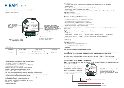
外观介绍装箱清单设备(x1)本用户指南中所有图片仅供参考,一切请以实物为准。
接近/光线传感器电源键麦克风*接线端子*接线端子L:火线N:零线L1~L3:负载。
每路负载范围:白炽灯≤800W(3路总负载≤2000W ),荧光灯/新风机≤400W(3路总负载≤1000W)A:RS-485信号线B:RS-485信号线背面安装设备关闭电源总闸。
安装及拆卸,请务必联系专业电工师傅安装。
安装/拆卸前请先确认电源总闸已关闭!安装时需配合标准86底盒,在墙壁86型开关、插座位置安装。
用一字螺丝刀伸入开启槽,撬开面板,分离面板和底壳组件。
将墙壁86接线盒里的火线接入底壳组件的L接口,零线接入N接口,灯控/新风控制线接入L1/L2/L3接口。
确认接线正确后,拧紧接线端子螺丝。
开启总闸的电源。
总闸电源开启后,设备自动开机。
扬声器电源键*在开机状态下操作:短按一次:息屏/进入屏保长按3秒:关机/重启长按10秒:强制重启G:地线(请勿遮挡,并保持传感器清洁以体验最佳效果)开启槽重要安全信息禁止自行改装或维修本产品;除废弃本产品时以外,禁止自行拆解。
— 否则可能导致触电、受伤或火灾。
安装涉及到强电操作,请务必联系专业电工师傅安装。
安装/拆卸前请先确认电源总闸已关闭。
禁止用湿手操作插座;禁止在浴缸附近或淋浴房内等环境处使用;禁止在室外使用。
— 否则可能发生触电或受伤。
禁止将设备安装在儿童和婴幼儿的接触范围之内。
使用设备前请先阅读用户指南。
请务必遵守以下安全注意事项。
— 因不遵守本用户指南说明而引起的任何损失,公司概不负责。
产品仅限室内使用。
用户指南(x1)螺丝配件(x1)用附带的螺丝将底壳组件固定到墙壁中的86接线盒里。
(注意 底壳组件 向上)将面板的上半部分对准并贴合到底壳组件(注意面板背面 向上),再将下半部分按进去,将面板重新卡在底壳组件上。
接火线接零线·拧螺丝请使用手动螺丝刀操作。
电动螺丝刀扭力较大可能会将螺丝或底壳组件拧变形,影响拆装。
智能压力开关操作手册一、特点●4位数字显示当前压力值。
● 2路开关量输出,带载能力1.2A●模拟量输出(4~20mA)●开关量可在零点到满度之间任意设定●外壳设有节点动作发光二级管,便于观察●按键调校及现场设置各种参数,操作方便●压力预设开关点和延滞切换输出二、概述智能压力开关是集压力测量,显示,输出、控制于一体的智能数显压力测控产品。
该产品为全电子结构,前端采用带隔离膜充油压阻式压力传感器,输出信号由高精度,低温漂的放大器放大处理,送入高精度的A/D转换器,转换成微处理器可以处理的数字信号,经过运算处理的信号控制两路开关,对控制系统压力进行测控。
该智能数字压力开关使用灵活,操作简单,调试容易,安全可靠。
广泛应用于水电,自来水,石油,化工,机械,液压等行业,对流体介质的压力进行测量显示和控制三、技术参数四、4.1机械连接:可以通过压力管接头(DIN3582外螺纹G1/4)(其他尺寸接头可在订货时说明),直接装在液压管路上。
在关键应用场合(如剧烈震动或冲击),压力管接头可以通过微型软管进行机械解耦。
4.2电气连接:1红:电源+ 2黄:电源-3 蓝:开关14 绿:开关25灰:4~20Ma为了防止电磁干扰的影响应注意以下事项:●线路连接尽量短●采用屏蔽线●尽量避免直接接近引起干扰的用户装置或电器和电子装置的接线●若用微型软管安装,壳体必须单独接地五、外形尺寸六、设置功能6.1开关量输出有两路开关量输出。
每路开关量输出可以设定1个压力开关点和一个开启延时值。
相应的输出会在开关点的吸合值到达时切换并在压力下降到低于释放值时回复。
6.2模拟输出根据型号规格:两路开关量+一路模拟量,带一路模拟输出。
可输出4~20mA6.3设置开关点(代号:)AL1H此值为开关1吸合值(压力到达此点时吸合,指示灯亮)。
AL1F此值为开关1释放值(压力到达此点时断开,指示灯灭)AL1D此值为开关1动作延时(切换前必须等待的时间秒数)AL2H此值为开关2吸合值(压力到达此点时吸合,指示灯亮)AL2F此值为开关2释放值(压力到达此点时断开,指示灯灭)AL2D此值为开关2动作延时(切换前必须等待的时间秒数)注:开关点由吸合值和释放值组态决定,吸合值大于释放值时为上限报警输出(常开功能),吸合值小于释放值时为下限报警输出(常闭功能)吸合值与释放值的差值为开关点的回差。
目录一、概述 (1)二、主要功能及技术参数 (1)三、保护功能及工作原理 (1)1、三段定时限电流保护 (1)2、零序保护(接地保护) (1)3、电压保护功能 (2)4、自动分、合闸控制功能 (2)5、重合闸功能 (2)6、自动复归功能 (2)7、负序电流检测功能 (2)四、控制器操作说明 (2)1、参数设置 (3)<1>、保护参数设置 (3)<2>、变比设置 (5)<3>、时钟设置 (5)<4>、密码修改 (5)<5>、清除记录 (5)<6>、终端信息 (5)2、显示信息 (6)<1>、保护参数 (6)<2>、变比参数 (6)<3>、事件记录 (6)<4>、手动控制 (6)<5>、保护实时数据 (6)<6>、开关量状态 (7)五、安装及接线说明 (7)六、手持无线遥控器使用说明 (8)七、短信操作说明 (8)八、注意事项 (9)九、订货须知 (9)十、附录 (9)一、概述YMT-500型智能开关控制器(简称“看门狗”)采用性能优越的32位处理系统,计算与处理能力强大,存储单元采用非易失性铁电存储技术,降低了数据丢失的可能性,提高了运行的可靠性,人机交互采用3.2寸触摸式液晶,方便管理人员查看参数和修改参数,支持多种通讯方式,支持GPRS在线通讯、WIFI通讯、SMS短信通讯、本地串口或RS485通讯。
该产品具有自动切除单向接地故障、隔离相间短路故障、断开过流负载、欠压过压保护功能,确保非故障用户的用电安全,并具有本地遥控、远程遥控分合闸功能。
智能开关控制器是集分界开关本体的智能控制和预付费于一体智能控制器。
实现保护控制功能和通信功能,控制器与开关本体通过控制电缆进行电气连接,实现其保护及自动监控功能。
该产品可广泛适用于智能电网建设、城乡电网的改造,是增加配电网可靠性、提高电能质量、提高配网运行水平的强大工具,也可做为10KV供电用户的开关控制器。
yeelight凌动开关说明书Yeelight凌动开关使用说明书一、产品介绍Yeelight凌动开关是一款智能家居产品,主要用于控制照明设备的开关。
它采用了无线通信技术,可以实现远程控制、定时开关和一键场景切换等功能。
凌动开关外观简洁,安装便捷,是您智能家居控制的理想选择。
二、产品特点1.远程控制:通过手机APP,您可以随时随地远程控制开关的状态,无需亲自到达开关处。
2.定时开关:您可以设置定时开关,实现每天自动开关灯光,提高居家生活的便捷性。
3.场景切换:支持一键场景切换,您可以预设多种场景模式,例如用餐模式、阅读模式和休息模式等,满足不同需求。
4. 节能环保:Yeelight凌动开关使用高效节能的LED技术,有效节约能源,减少能源消耗。
5. 多设备控制:您可以将多个Yeelight凌动开关连接在一起,并集中控制,方便实用。
三、产品安装1.确认电源:在安装之前,请确保开关位置附近有可用的电源。
2. 选择安装位置:选择合适的位置安装Yeelight凌动开关,通常建议在进门处或居住环境中频繁经过的地方安装。
3.安装开关壳体:用螺丝将开关壳体牢固地安装在墙壁上,保证稳定性。
4.连接电源线:根据产品连接图示,将电源线准确连接到相应的接线柱上。
请确保电源线的接线正确无误,以免影响使用安全。
5.安装外壳:将开关壳体盖上外壳,确保外壳安装稳固。
6.安装电池:打开开关外壳,安装电池,并按照正确方向连接电池。
四、手机APP设置2.注册登录:打开APP,并按照提示进行注册和登录操作,创建属于您自己的账户。
3.添加设备:在APP中选择添加设备,然后按下开关面板上的按键三次,直到指示灯快闪示成功配对。
4.控制设备:配对成功后,您可以通过APP控制开关的开关状态,并进行其他高级设置,例如定时开关和场景切换等。
五、常见问题解决1.开关无法正常工作:请检查开关电源是否正常连接并连接稳定。
2.APP无法与开关连接:请确认手机与开关处于同一Wi-Fi网络环境下,并尝试重新配对设备。
智能开关使用说明书
———— 一/二/三位暗装智能开关
尊敬的用户:
首先感谢您选择了我公司的智能产品,智能科技有限公司全体同仁祝您全家生活愉快!我们的产品将给您的生活带来舒适和便捷,为了让您能更好的安装和使用该产品,在这里我们提醒您认真阅读此说明书。
如有疑问请登联系我们,我们竭诚为您服务。
一、产品说明
NT-JJ3309型一位暗装智能开关,NT-JJ3310型二位暗装智能开关,NT-JJ3311
型三位暗装智能开关是尼特智能开关系列产品之一,它主要用于控制灯具及电器的开关。
其外型尺寸为86×86×45,可与普通86型开关互换安装,不仅可直接取代传统的墙壁开关,保留原有手动功能,而且增加了射频遥控、远程电话遥控、远程网络遥控等具有现代意识的数字化功能,是现代家居智能化的理想选择。
二、产品图示及接线图、安装图、拆卸图
一位暗装智能开关 二位暗装智能开关 三位暗装智能开关
220V N (零线)L (火线)
220V 灯泡1灯泡2灯泡3
N (零线)L (火线)220V 一位暗装智能开关 接线图灯泡2
灯泡1N (零线)L (火线)三位暗装智能开关接线图二位暗装智能开关
接线图灯泡1
安装图3
4
52
13 拆卸图
三、安全警示
1、为了您的安全,在使用本产品之前必须详读此说明书。
2、聘请专业电工为您安装或拆卸开关,安装或拆卸开关时,必须先切断电源。
3、本开关安装在洗漱间、浴室等潮湿的地方时应装防溅盒或采取防潮措施。
4、配接负载时应严格控制在负载功率之内。
5、安装开关时严禁锤打、过力紧固以防面板变形,同时严禁金属物掉入开关外壳内。
四、概念解释:
1、学习状态:此时可以把遥控器的某一指令代码,存储于开关(插座、单路控制器)
的记忆芯片中,从而实现两者之间的相互确认
2、对码:实现遥控器和开关(插座、单路控制器)的相互确认。
如果不进行对码,
遥控器则不能控制该开关(插座、单路控制器)
3、数字对码:实现遥控器数字键和开关(插座、单路控制器)的相互确认。
即实现
用遥控器的某一数字键控制该开关(插座、单路控制器)的开、关状
态,从而达到控制灯光和电器的目的
4、情景对码:实现遥控器情景键和开关(插座、单路控制器)的相互确认。
在进行
情景设置之前,必须先进行情景对码,已进行过数字对码的开关(插
座、单路控制器),则不必进行此程序
5、情景设置:设置遥控器一键控制若干个灯具、电器的开关状态。
通过灯光、电器
的变换组合营造出不同氛围的生活场景,只要按动一键即可实现看电
视、用餐、会客等不同的场景需求
五、功能概述:
1、自动关断功能:停电自动转入关断状态。
2、断电记忆功能:可记忆断电前设置的各种对码和情景模式。
3、远程控制功能:经过智能终端、电话远程控制器可实现网络、电话、手机的远程
控制功能。
4、情景设置功能:与遥控器配合使用可进行个性化情景设置。
5、夜光指示功能:可在黑暗中指示开关的位置。
6、编码学习功能:用户可以根据自己的意愿随意设定遥控器和开关的对应关系。
7、其它功能:(1)单火线供电,安装方便。
(2)可同时存储8个遥控器的控制码。
六、功能设置
1、数字对码(开关上的每个按键最多能存储8个遥控器的控制码,最多能学习一个
遥控器的2个数字键)
数字对码操作步骤如下:
(1)(2)(3)
(1)持续按住开关按键约8秒,开关按键上的指示灯亮,松开按键(开关按键指示灯可亮5秒,以下操作必须在5秒之内完成);
(2)按下遥控器上任意一个数字键;
(3)开关按键上的指示灯闪烁1次,表示操作成功。
说明:(1)、第3步中开关按键上的指示灯闪烁4次,表示遥控器上的该数字键原本可以控制该路灯光,现在已被清除。
(2)、第3步中开关按键上的指示灯闪烁2次:
①、若此遥控器的其它数字键能控制该路灯光,表示此开关按键已存满
该遥控器上的2个数字码。
②、若此遥控器的其它数字键不能控制该路灯光,表示此开关按键已存
满8个遥控器的地址码。
2、情景对码(开关上每个按键最多能存储8个遥控器的情景控制码)
如果该开关按键和遥控器没有进行过数字对码,用户要想此开关参与情景模式
设置,必须先进行情景对码,情景对码和数字对码操作步骤相似,具体如下:(1)持续按住开关按键约8秒,开关按键上的指示灯亮,松开按键(开关按键指示灯亮5秒,以下操作必须在5秒之内完成);
(2)按下遥控器上任一情景键;
(3)开关按键上的指示灯闪烁1次,表示情景对码成功。
说明:(1)、第3步中若开关按键上的指示灯闪烁4次,表示遥控器和此开关按键已进行过情景对码,现在已被清除。
(2)、第3步中若开关按键上的指示灯闪烁2次,表示此开关按键已存满8个遥控器的情景码。
(3)、如果开关按键和遥控器已经进行了数字对码,则不必进行情景对码,该开关按键即可参与情景设置了。
(4)、无论是一位、二位还是三位开关,其中的每个按键所控制的那路灯想参与情景设置,都需和遥控器进行数字对码或情景对码。
(5)、每个开关按键,只需和一个遥控器进行一次情景对码,它所控制的那路灯就可参与该遥控器的所有情景设置。
3、情景设置(进行情景设置之前,必须先进行对码)
通过设置,用户可以设置出自己喜欢的情景,让灯光进入预定的模式。
由
于不同的遥控器情景设置方式不同,具体设置步骤见遥控器的使用说明
书。
4、清码:
(1)如果用户想清除某一开关按键所存储的所有数字码和情景码,则长按住该开关按键,直到此开关按键上的指示灯先被点亮,再由亮变灭后松开开关
按键即可。
(2)如果用户想清除遥控器上某一数字键对某一开关按键的控制,具体操作见‘数字对码’。
(3)如果用户想清除某一遥控器对某一开关按键的所有控制,具体操作见‘遥控器说明书’。
七、开关技术参数
1、工作电压:220V~ 50Hz
2、工作温度:0~45°C
3、工作湿度:≤90%RH
4、接收灵敏度:≤-100dbm
5、工作频率:
6、单路负载功率:≤220W
7、负载类型:白炽灯、节能灯、日光灯、射灯
八、提示
单火暗装智能开关安装接电后需要等待约40~90秒,在此期间开关不接收任何指令。
九、常见故障:。