IRS2183STRPBF资料
- 格式:pdf
- 大小:475.02 KB
- 文档页数:24
HIN
up to 600 V
TOLOADVCCVBVSHO
LOCOMHINDTVSS
LINVCCLINVSSRDTVCCVBVSHO
LOCOMHIN
LIN
LIN
HIN
up to 600 V
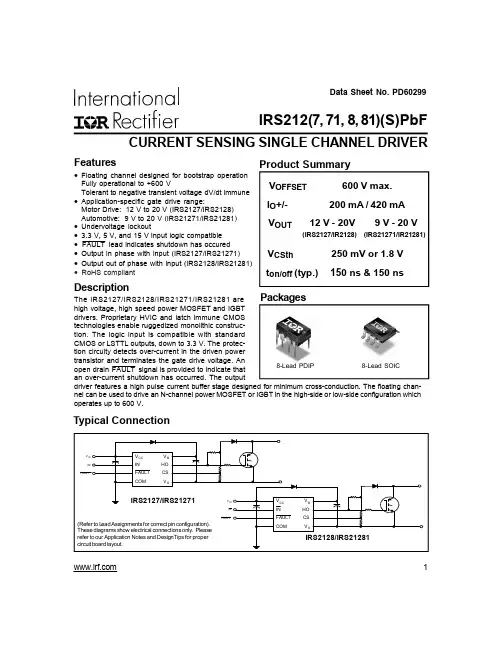
TOLOADVCCTypical ConnectionHALF-BRIDGE DRIVERFeatures•Floating channel designed for bootstrap operation•Fully operational to +600 V•Tolerant to negative transient voltage, dV/dtimmune•Gate drive supply range from 10 V to 20 V•Undervoltage lockout for both channels•3.3 V and 5 V input logic compatible•Matched propagation delay for both channels•Logic and power ground +/- 5 V offset•Lower di/dt gate driver for better noise immunity•Output source/sink current capability 1.4 A/1.8 A
IRS21834IRS2183
www.irf.com1IRS2183/IRS21834(S)PbFData Sheet No. PD60265
(Refer to Lead Assignment for correct pin configuration) These diagrams show electricalconnections only. Please refer to our ApplicationNotes and DesignTips for proper circuit board layout.DescriptionThe IRS2183/IRS21834 are high voltage,high speed power MOSFET and IGBTdrivers with dependent high and lowside referenced output channels. Pro-prietary HVIC and latch immune CMOStechnologies enable ruggedized mono-lithic construction. The logic input iscompatible with standard CMOS orLSTTL output, down to 3.3 V logic. Theoutput drivers feature a high pulse cur-rent buffer stage designed for minimumdriver cross-conduction. The floating channel can be used to drive an N-channel power MOSFET or IGBTin the high side configuration which operates up to 600 V.Feature ComparisonPartInputlogicCross-conductionpreventionlogicDeadtime(ns)Ground PinsTon/Toff(ns)2181COM21814HIN/LINnononeVSS/COM180/2202183Internal 5000COM21834HIN/LINyesProgram 400-5000VSS/COM180/2202184Internal 5000COM21844IN/SDyesProgram 400-5000VSS/COM680/270Packages8-Lead PDIPIRS2183
8-Lead SOICIRS2183S14-Lead PDIPIRS21834
14-Lead SOICIRS21834S元器件交易网www.cecb2b.comIRS2183/IRS21834(S)PbF
www.irf.com 2SymbolDefinitionMin.Max.UnitsVBHigh side floating absolute voltage-0.3620 (Note 1)VSHigh side floating supply offset voltageVB - 20VB + 0.3VHOHigh side floating output voltageVS - 0.3VB + 0.3VCCLow side and logic fixed supply voltage-0.320 (Note 1)VLOLow side output voltage-0.3VCC + 0.3DT Programmable deadtime pin voltage (IR21834 only)VSS - 0.3 VCC + 0.3VINLogic input voltage (HIN & LIN)VSS - 0.3VCC + 0.3VSSLogic ground (IR21834 only)VCC - 20VCC + 0.3dVS/dtAllowable offset supply voltage transient—50V/ns(8-lead PDIP)—1.0PDPackage power dissipation @ TA ≤ +25 °C(8-lead SOIC)—0.625 (14-lead PDIP) — 1.6 (14-lead SOIC)—1.0(8-lead PDIP)—125RthJAThermal resistance, junction to ambient(8-lead SOIC)—200(14-lead PDIP)—75(14-lead SOIC)—120TJJunction temperature—150TSStorage temperature-50150TLLead temperature (soldering, 10 seconds)—300V
°C°C/WWAbsolute Maximum RatingsAbsolute maximum ratings indicate sustained limits beyond which damage to the device may occur. All voltage param-eters are absolute voltages referenced to COM. The thermal resistance and power dissipation ratings are measuredunder board mounted and still air conditions.
Note 2: Logic operational for VS of -5 V to +600 V. Logic state held for VS of -5 V to -VBS. (Please refer to the Design TipDT97-3 for more details).Recommended Operating ConditionsThe input/output logic timing diagram is shown in Fig. 1. For proper operation the device should be used within therecommended conditions. The VS and VSS offset rating are tested with all supplies biased at 15 V differential.
VB High side floating supply absolute voltage VS + 10VS + 20VS High side floating supply offset voltage Note 2 600VHOHigh side floating output voltageVSVBVCCLow side and logic fixed supply voltage1020VLOLow side output voltage0VCCVIN Logic input voltage (HIN & LIN) VSS VCCDT Programmable deadtime pin voltage (IR21834 only)VSS VCCVSSLogic ground (IR21834 only)-55TAAmbient temperature-40125°CVSymbolDefinitionMin.Max.UnitsNote 1: All supplies are fully tested at 25 V and an internal 20 V clamp exists for each supply.元器件交易网www.cecb2b.com
www.irf.com3IRS2183/IRS21834(S)PbF
Static Electrical CharacteristicsVBIAS (VCC, VBS) = 15 V, VSS = COM, DT= VSS and TA = 25 °C unless otherwise specified. The VIL, VIH, and IINparameters are referenced to VSS/COM and are applicable to the respective input leads: HIN and LIN. The VO, IO, andRon parameters are referenced to COM and are applicable to the respective output leads: HO and LO.Symbol Definition
Min. Typ. Max. Units Test ConditionsVIHLogic “1” input voltage for HIN & logic “0” for LIN 2.5 — —VILLogic “0” input voltage for HIN & logic “1” for LIN——0.8VOHHigh level output voltage, VBIAS - VO——1.2IO = 0 AVOLLow level output voltage, VO——0.2IO = 20 mAILKOffset supply leakage current——50VB = VS = 600 VIQBSQuiescent VBS supply current2060150IQCCQuiescent VCC supply current0.41.01.6mAIIN+Logic “1” input bias current—2560HIN = 5 V, LIN = 0 VIIN-Logic “0” input bias current——1.0HIN = 0 V, LIN = 5 VVCCUV+VCC and VBS supply undervoltage positive going8.08.99.8VBSUV+thresholdVCCUV-VCC and VBS supply undervoltage negative going7.48.29.0VBSUV-thresholdVCCUVHHysteresis0.30.7—VBSUVHIO+Output high short circuit pulsed current1.41.9—VO = 0 V,PW ≤ 10 µsIO-Output low short circuit pulsed current1.82.3—VO = 15 V,PW ≤ 10 µsV