H2用户手册V1.0
- 格式:doc
- 大小:6.04 MB
- 文档页数:46

Models:LIVS09HP115V1B LIVS12HP115V1B LIVS09HP230V1B LIVS12HP230V1B LIVS18HP230V1B LIVS24HP230V1B LIVS30HP230V1B LIVS36HP230V1BHIGH-WALL DUCTLESSAIR CONDITIONING &HEATING SYSTEM OWNER’S MANUALTable of ContentsIntroduction . . . . . . . . . . . . . . . . . . . . . . . . . . . . . . . . . . . . . . . . . . .2Nomenclature . . . . . . . . . . . . . . . . . . . . . . . . . . . . . . . . . . . . . . . . . .2Safety Precautions . . . . . . . . . . . . . . . . . . . . . . . . . . . . . . . . . . . .3-4Installation Schematic . . . . . . . . . . . . . . . . . . . . . . . . . . . . . . . . . . . 5System Functions . . . . . . . . . . . . . . . . . . . . . . . . . . . . . . . . . . . . .6-8Operation of Wireless Remote Contoller . . . . . . . . . . . . . . . . . .9-16Care and Cleaning . . . . . . . . . . . . . . . . . . . . . . . . . . . . . . . . . . . . .17Troubleshooting . . . . . . . . . . . . . . . . . . . . . . . . . . . . . . . . . . . .18-19Energy Saving Tips . . . . . . . . . . . . . . . . . . . . . . . . . . . . . . . . . . . . .20Warranty . . . . . . . . . . . . . . . . . . . . . . . . . . . . . . . . . . . . . . . . . . .BackThank you for choosing aLivo Heat Pump System!You can feel confident in your selection because the same pride in craftsmanship and engineering knowledge that goes into millions of other Gree installed products worldwide has gone into your unit.Please read this owner’s manual carefully before operation and retain it for future reference.INTRODUCTIONSuperior Design for Superior PerformanceGree’s Livo Inverter-driven, Mini Split Heat Pumps are beautifully designed to deliver effective cooling or heating, while fitting unobtrusively into any decor. The indoor unit’s aesthetically pleasing, minimalist design blends nicely in any home or office.Your Livo unit offers quiet, energy-efficient comfort, powered by Gree’s famous G10 Inverter technology. To speed the process of bringing conditioned air exactly where you want it, the unit features both horizontal and vertical air flow control. Customizable mode controls allow you to adjust fan speeds, select sleep-time settings and more, all through the easy-to-use wireless remote controller, or an optional Wired Tether Controller.There’s even a Turbo, Power Failure Memory and other advanced features to make the Livo system even more versatile, for year-round comfort and energy savings. NOMENCLATUREPlease read the following before operation.symbol on the unit and in instructions or manuals, be alert to the potential for personal injury. Understand these signal words: DANGER, WARNING, and CAUTION. These words are used with the safety-alert symbol.DANGER identifies the most serious hazards which will result in severe personal injury or death.WARNING signifies hazards which could result in personal injury or death. CAUTION is used to identify unsafe practices which may result in minor personal injury or product and property damage.NOTE is used to highlight suggestions which will result in enhanced installation, reliability, or operation.NOTE:Your actual air conditioning & heating system and related devices may differ from the images shown in this manual.Please read the following before operation.:::::Front Panel DisplayThe front panel on the Livo indoor unit contains system status lights and easy-to-read LED display. NOTE:The indoor unit display panel can be turned ON or OFF via the LIGHT buttonon the remote controller. See "LIGHT" button description for more detail.INSTALLATION SCHEMATIC1. 2.3.Air Filter4. 5.6.8. 9.34WHISPER QUIETNot only are the Gree systems energy efficient but they are quiet too. Livo High-Wall units operate with sound pressure levels starting as low as 28 dB(A).MULTI FAN SPEEDSWhether operating in either Cooling or Heating mode, the indoor fan can be set to your choice of four different speeds (Low, Medium, High or Turbo) to achieve maximum comfort. INTELLIGENT PRE-HEATINGThe Livo system guards against the annoying cool air blown into the room in heating mode. The system constantly monitors the discharge air temperature. It will delay the indoor fan until the indoor coil has warmed up to prevent blowing uncomfortable cool air into the room.I FEEL MODEThe unit will sense room temperature at the remote controller instead of at the indoor unit during cooling mode. It then adjusts airflow and temperature accordingly for the ultimate in personal comfort control and energy savings.ADJUSTABLE AIRFLOWThe Livo system has a bi-directional airflow control for maximum comfort. The indoor unit has adjustable vertical swing louvers and can be set in multiple discharge directions from the wireless remote controller.TURBO MODEUse Turbo Mode for situations where you wish to achieve the desired room temperature in the shortest possible time. This mode runs the unit at ultra high speeds for quickest results. FREEZE GUARDRoom Freeze Guard protection will automatically keep the room temperature from getting too cold, where water pipes might freezeTIMER MODEThe unit can be programmed to turn ON or OFF after a specific amount of time. The time period is adjustable between one half and 24 hours.MODE BUTTONThe unit can be set to five different operating modes: HEAT, COOL, DRY, FAN ONLY and AUTO. NOTE:AUTO MODE has fixed setpoints of 68° F heating and 77° F cooling, whichare not adjustable. The system will automatically select heating or cooling to maintain room temperature within this band.SLEEP MODEThe Livo offers a Sleep Mode function for your comfort. The unit will automatically adjust room temperature during your sleep time. This slight change in temperature will not affect your comfort level due to the natural effects that sleeping has on the body, but it will save on energy consumption and will lower electric bills.ENERGY SAVINGS MODEThis feature will automatically select the optimal compressor and fan speeds to allow for energy savings while operating in Cooling or Heating modes. The compressor and fan will automatically slow down as the room temperature reaches the set point.SELF-DIAGNOSISLivo has a built-in computer which uses real-time diagnostics which help prolong the unit’s life. The automatic diagnosis feature continuously scans for errors or malfunctions and fault codes are shown on the unit display to facilitate troubleshooting and repair.POWER FAILURE MODEPower interruptions are no problem for the Livo system. User selections and system parameters are stored in non-volatile memory. These parameters are retained during a power failure. When power is returned, the Livo system will automatically return to the last operating mode. INTELLIGENT DEFROSTThe Livo Intelligent Defrost function increases room comfort and saves energy by eliminating unnecessary defrost cycles. In heating mode, the unit will monitor the outdoor coil for frost build up. Once frost buildup has been detected, the system will switch into a defrost mode to remove the frost.POLYMERIC AIR FILTERThe polymeric mesh filters save energy by preventing the indoor coils from being plugged with dirt and lint. This economical and sturdy filter may be washed, vacuumed and reused. FAHRENHEIT °F/CELSIUS °CThe remote controller and indoor wall unit front panel can be set to display in either °F or °C. PRIVACY LOCK MODEThe wireless remote controller has a Lock feature. The Lock averts unauthorized access or tampering with system settings.AGENCY LISTINGSAll systems are listed with AHRI (Air conditioning, Heating, and Refrigeration Institute) and are ETL certified per UL Standards.Remote ControllerINTRODUCTION FOR ICONS ON DISPLAY SCREENOPERATION OF WIRELESS REMOTE CONTROLLERPart Name1. ON/OFF Button2. Fan Button3. Mode Button4. Up Button5. Swing Button6. Turbo Button7. Down Button8. Temp Button9. Sleep Button 10. I Feel Button 11. Clock Button 12. Light Button13. Timer On/Off Button13579112468101213Auto ModeCool Mode Dry Mode Fan Mode Heat Mode ClockSleep Mode I Feel Function LightSend Signal Turbo Mode Set Fan SpeedOperation ModeTemp.Display TypeSet Temperature Set Time Timer On/Off Privacy Lock Up &Down SwingSet Temp.IndoorAmbient Temp.OutdoorAmbient Temp.Temp. Display TypeFreeze GuardDISPLAYING SETPOINT OR INDOOR TEMPERATUREON FRONT PANEL:The setpoint temperature or room temperature can be displayed onthe front panel. Only setpoint temperature is displayed on the remotecontroller.When the “TEMP” button is pushed once, the temperatureindicator is displayed. This indicates that the setpoint temperatureis displayed on the front panel.” button is pushed a second time, the display willThe room temperature will be displayed for only 5 seconds beforereverting back to displaying room setpoint.REMOTE CONTROLLER OPERATIONSThe wireless remote controller is sleek, versatile and allows you to change room temperatures and functions on your Vireo system from the palm of your hand. The large LCD display and buttons make it easy-to-understand and easy-to-use.The remote controller is set from factory to display temperatures in °F . If °C is desired, turn the remote controller OFF with the ON/OFF button and then press “MODE “ and “” buttons on the remote simultaneously for 5 seconds.ON/OFF BUTTONWhen the system is in OFF mode, the remote controller will displaythe time and last room setpoint. When you press the ON/OFFbutton, this indicator will be displayed and the unit will start inthe last operating mode and room setpoint.NOTE: If the ON/OFF button is pressed too soon after astop, the compressor will not start for 1 to 5 min. due to theinherent protection against frequent compressor cycling.ON Mode Display Room Temperature DisplayPRIVACY LOCKThe Privacy Lock prevents unauthorized access to the unit controls and prevents tampering with system settings. The remote controller can be locked by pushing the""and " " buttons simultaneously for 5 seconds. The Privacy Lock icon will be displayed on the remotecontroller. Repeat the process to unlock the remote controller.UPrivacy Lock DisplayVERTICAL SWING LOUVERS•Press the Vertical Swing Louver button to select five differentvertical (up & down) air discharge directions including ContinuousSweep. The Swing Louver icon will be displayed. Press thisbutton to set swing angle, which changes in direction as below:Indicates louver swings up and down in the five directions, as shown.102345Swing Louver Display I Feel ModeI FEEL MODEremote controller instead of at the indoor unit during coolingmode. It then adjusts airflow and temperature accordingly forthe ultimate in personal comfort control and energy savings.Press the button again to exit this function. For best performance,keep remote controller away from heat or cold temperaturesources while using this function.MODE BUTTONUse the “MODE ” button to select one of the available modes.The selected mode will be displayed on the remote controller andthe appropriate light will illuminate on the front display panel.AUTO –Unit will automatically select heating or cooling tomaintain room temperature between 68°F and 77°F .The remote controller will display the Auto Mode icon withno setpoint. COOL –To cool to selected setpoint and remove moisture. Press or to adjust set temperature. System varies compressor speed to maintain desired temperature. HEAT –To heat to selected room setpoint. Press or to adjust set temperature. System varies compressor speed to maintain desired room temperature.FAN ONLY –To circulate air without heating or cooling. Use Fan Speed button to select speed from low to high.DRY –SelectDRY MODE to increase moisture removal during warm humid conditions. In this mode, fan speed cannot be adjusted.1. If the Room Temperature is more than 4°F above the set temperature, thesystem will be operating in cooling mode with low fan speed.2. If the Room Temperature is between 4°F higher than, and 4°F less than, the set temperature, the system will cycle 6 minutes ON and 4 minutes OFF in cooling mode. The indoor fan will be at low speed.3. If the Room Temperature is more than 4°F below the set temperature, the system will be OFF and the indoor fan will be at low speed.:::::Icons Displayed FREEZE GUARDIn Heat mode, press"TEMP"and "CLOCK" buttons simultaneouslyto start up 46°F heating function. When this function is started up,"($)"and "46°F" will be displayed on the remote controller, andthe unit will maintain room temperature above 46°F . Press"TEMP"and "CLOCK" buttons simultaneously again to cancel FreezeGuard protection.Freeze Guard DisplayTIMER SETTINGTimer-ON /Timer-OFF BUTTONTo set when you want the unit to turn On at the end of a selectedtime period, use the button labeled “Timer-ON /Timer-OFF”on theremote controller. Press this button to make the clock icon disappear,replaced with the word “ON” (blinking). Press or buttons toadjust timer setting 1 minute at a time. Press and hold or button to set timer more quickly. Press“Timer-ON/Timer-OFF”button again to confirm setting, and the word “ON” will stopblinking. To cancel, press“Timer-ON /Timer-OFF” button again.To set when you want the unit to turn Off at the end of a selected time period, use the same button. Press this button to make the clock icon disappear, replaced with the word “OFF” (blinking).Adjust settings the same as with “Timer-ON /Timer-OFF”settings.NOTE: Under Timer On and Off status, you can set“Timer-ON /Timer-OFF”simultaneously. Before setting timer, be sure to set clock to correct time.TURBO MODEThe desired room setpoint can be achieved faster in TURBOmode. After selecting the“HEAT ”or“COOL ” mode button,push the“TURBO ”button. The TURBO icon will bedisplayed on the remote controller and the unit will run at anultra-high speed. To deactivate the feature, push the“TURBO ”button again. The unit will return to normal operation.Timer Setting ON/OFF Turbo Mode DisplayFAN BUTTONPress the FAN button to adjust the indoor fan speed: Low ( ), Medium ( ), High ( ), Turbo and Auto.NOTE: Turbo function is not available in Dry and Auto Modes.The Livo unit will select proper fan speed automatically according to ambient temperature.CLOCK SETTINGPress this button to set clock time.“ ” icon on remote controllerwill blink. Within 5 seconds, press orbutton to set clock time. With each pressing of or buttons, clock time will increaseor decrease 1 minute. To quickly adjust time setting, press andhold or button for 2 seconds. Release button when youhave reached the desired time setting. Press “CLOCK” button toconfirm the time, and “ ” icon will stop blinking.NOTE: Clock time adopts 24-hour mode. A 12-hour timeformat is not available.•Turbo function is not available in Dry and Auto mode.•The fan operates at low speed in Dry and Auto modes, and thespeed cannot be adjusted.•When Auto is selected, the unit will select the proper fan speedautomatically, according to the ambient temperature.Fan Display Clock Setting DisplayLIGHT BUTTONPress this button to turn off display light on indoor unit.Press again to turn it back on.Light DisplayENERGY-SAVINGIn Cool mode, press"TEMP"and"CLOCK" buttons simultaneouslyto start the energy-saving function."SE" will be shown on remotecontroller, and the unit will adjust the set temperature automaticallyto reach to the best energy-saving effect. Press"TEMP"and"CLOCK"buttons simultaneously again to cancel energy-saving mode.Energy Saving DisplaySLEEP MODEThe Livo system will automatically adjust room temperature during your sleep time. This slight change in temperature will not affect your comfort level due to the natural effects that sleeping has on the body, but it will save on energy consumption and will lower your electric bill. Press the SLEEP button to select Sleep Mode or Cancel. The SLEEP icon will appear.In Sleep Mode the unit will slowly relax the room set temperature by up to 4° F until Sleep Mode is cancelled.Sleep Mode DisplayCooling Mode Heating ModeUse insulated object to press the Aux. button.CHANGING BATTERIES AND ADDITIONAL NOTESTo change batteries, slide cover off battery compartment on back of remote controller. Remove and safely discard old batteries. Insert two new AAA 1.5V dry batteries, using correct polarity. Reattach back cover.NOTE:•If the remote controller will not be used for a long time, remove batteries to prevent leakage damage.•Be sure to aim the remote controller at the receiver of the main unit when operating.•When remote emits a signal, icon will flicker; a tone will be heard when unit receives that signal.DAMAGED OR LOST REMOTE CONTROLLERIf remote controller is lost or damaged, the Livo system can be turned off directly from the in-door unit. Lift the front panel of the indoor wall unit, then press the AUX button to turn on or turn off.When the unit is on, it will operate in AUTO Mode.Removeold batteries Installnew batteriesCHANGING BATTERIESAux. ButtonPanelAIR FILTER CLEANINGChanging your air filter on a regular basis prevents many problems. Dirty air filters will affect the performance and the longevity of your unit. It is recommended that air filters be cleaned every three (3) months. To access and clean the filter:CARE AND CLEANINGFRONT PANEL CLEANINGWash the front panel using warm water and mild detergent with a soft cloth or soft brush.NOTE:Do not use bleach,abrasives or water above 110°F (45°C) as it may cause discoloration or damage to the surface of the unit.1.Open Front PanelFirmly grasp both sides of the front panel and pull upwardto about 60 degree angle. (NOTE:do not force panel open).2.Remove FilterRemove the filter as indicated in the figure at right.3. Clean FilterUse vacuum to clean the filter.When the filter is very dirty, use warm water (below 110°F )to clean it, and then dry filter before replacing.4.Reinstall FilterReinstall the filter and then close the panel cover tightly.ENERGY SAVING TIPS1. Reduce room setpoint at night:During the nighttime hours you don't require thesame level of conscious cooling or heating. Try using Sleep Mode to gradually relaxroom temperature and allow the unit to run less and save energy.2. Curtains and shades:In the summer, it is recommended to block the effects of thesun. Close window curtains and shades on the south and west side of your home tohelp block solar heat. In winter, the sun is your friend. Open curtains and shades toallow solar heat into your room.3. Close doors:If you don’t need to heat and cool your whole home, confine the heat-ing and cooling to one room by closing doors.4. Service the unit:Some basic maintenance might be all you need. The outdoor unitwill greatly benefit from a good hosing off, especially in treed areas where seeds andother debris can stick to coil fins and make the unit work up to 15% harder!5. Rearrange the room:Furniture that obstructs airflow means you could be heatingand cooling the back of a chair instead of the actual living space. Remove or rearrangeobstacles blocking airflow.6. Try 75 degrees:75°F is a good point for an air conditioner to run at its optimalperformance level. Even a 5-degree change in temperature can make your unit useup to 40% more energy.7. Lighting:Turning lights off can help reduce your heat. Each light bulb is a tiny heater.Your air conditioner must waste energy overcoming the heat from your lights to reachand hold your desired room temperature.8. Is anyone home?If possible, while you're away turn your unit to Auto mode andmake sure windows and curtains are closed. Although room temperature may be lessthan optimal for a few minutes when you return, the unit will soon have the roomback to your desired temperature.9. Don't forget the fan:The fan is much like a car. The faster it runs, the more energy ituses. Sometimes we need the car to go fast, but slow is good enough most of the time.Try saving money by using the comfortable quiet low fan speed as much as possible.201.2. 3.4.5. 6. 7. 8. 9.。
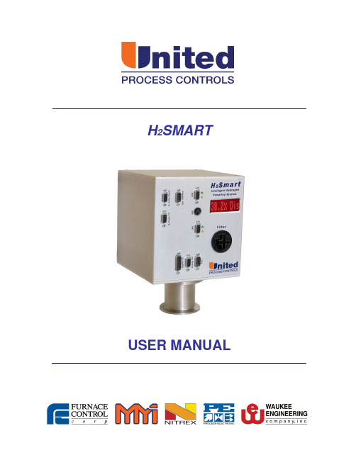
H2SMARTUSER MANUALLEGAL NOTICEMay 2008 – Revision 1THIS MANUAL IS SUPPLIED IN ONE (1) COPY.No part of this publication may be duplicated, copied, and/or transmitted without the prior written permission of United Process Controls.The information contained in this document is STRICTLY CONFIDENTIAL and PROPRIETARY to United Process Controls, and shall not be: i) reproduced or disclosed in part or in whole, ii) used for any design or manufacturing of heat treating and/or control equipment, or any other purpose except for that which it is supplied under the terms of the Contract, unless the express written authorization is obtained from United Process Controls.Drawings and photographs included in the documentation are the property of United Process Controls, and it is strictly forbidden to reproduce them, transmit them to a third party, or use them for manufacturing and/or design of equipment. Sub-licensing of any technical information contained in this Documentation is strictly forbidden under the terms of the Contract.United Process Controls reserves the right to modify this document without prior notice. WARRANTYUnited Process Controls (UPC) warrants its goods as being free of defective materials and faulty workmanship. Contact your local sales office for warranty information. If warranted goods are returned to UPC during the period of coverage, UPC will repair or replace without charge those items it finds defective. The foregoing is Buyer's sole remedy and is in lieu of all other warranties, expressed or implied, including those of merchantability and fitness for a particular purpose. Specifications may change without notice. The information we supply is believed to be accurate and reliable as of this printing. However, we assume no responsibility for its use.CE Conformity (Europe)This product conforms to 73/23/EEC, the Low Voltage Directive, and 89/336/EEC, the EMC Directive.AMS Conformity (North America)This product conforms to SAE Aerospace Material Specifications AMS 2759/10 for nitriding and 2759/12 for nitrocarburizingTABLE OF CONTENTS1. INTRODUCTION (5)1.1. Overview (5)2. SPECIFICATIONS (6)2.1. Physical (6)2.2. Performance (6)2.3. Operating (6)2.4. Calibration (recommendation) (6)3. INSTALLATION (7)3.1. Overview (7)3.2. Panel Mount Model (7)3.3. Port Mount Model (10)3.4. Installation Steps – Panel Mount (14)3.4.1.Step 1 (14)3.4.2.Step 2 (14)3.4.3.Step 3 (15)3.4.4.Step 4 (16)3.5. Installation Steps – Port Mount (16)3.5.1.Step 1 (16)3.5.2.Step 2 (17)3.5.3.Step 3 (18)4. ELECTRICAL INSTALLATION (19)5. OPERATING INSTRUCTIONS (26)6. MAINTENANCE (27)6.1. Sample Gas Filter (27)6.2. Sample Gas Pump (29)7. CONFIGURATION (29)8. CUSTOMER SUPPORT (29)8.1. Contacts (29)TABLE OF FIGURESFigure 1 Panel Mount Model (7)Figure 2 Panel Mount Front View (8)Figure 3 Panel Mount Side View (9)Figure 4 Panel Mount Bottom View (10)Figure 5 Port Mount Model (10)Figure 6 Port Mount Front View (11)Figure 7 Port Mount Side View (12)Figure 8 Port Mount Side View (13)Figure 9 Panel Mount Step 1 (14)Figure 10 Panel Mount Step 2 (14)Figure 11 Panel Mount Step 3 (15)Figure 12 Panel Mount Step 3 (15)Figure 13 Panel Mount Step 4 (16)Figure 14 Port Mount Step 1 (16)Figure 15 Port Mount Step 1 (17)Figure 16 Port Mount Step 2 (17)Figure 17 Port Mount Step 3 (18)Figure 18 Electrical Installation (19)Figure 19 Connectors (21)Figure 20 Connectors (22)Figure 21 LAN Connector (23)Figure 22 CAN Connector (23)Figure 23 Filter Cover (27)Figure 24 Filter Holder (28)Figure 25 Filter Cartridge (28)1. INTRODUCTION1.1. OverviewThe H2Smart is an integrated sampling system designed to measure hydrogen content with high accuracy in nitriding and nitrocarburizing atmospheres and to calculate the parameters necessary for process control. A unique measuring cell design and advanced electronics eliminate the need for a reference gas cell, thus simplifying the installation.An integrated sampling pump with variable output and a flow monitoring circuit with alarm and pump saturation warning insure reliable sampling. The pump provides a continuously controlled flow despite most sampling line obstructions or filter contaminations, thus assuring accurate measurements and better process control. In addition, an alarm is triggered notifying that the lines are clogged.The sample gas flow is measured with a thermal mass flow meter with integrated thermal conductivity compensation ensuring accurate flow measurement for all gas compositions of the specified gas system. A sample gas pump with variable output and a digital flow regulator are used to form a closed loop sampling system that ensures constant gas flow through the analyzer.The measuring block is maintained at a set temperature to protect the system from moisture formation and cell contamination during nitrocarburizing and post oxidation processes.The system status and measured results are displayed on a large, easy to read alphanumerical display.2. SPECIFICATIONS2.1. PhysicalPanel mount modelWidth (including mounting bracket): 7.28” (185mm)Height: 8.25” (209.53mm)Depth: 7.6” (193mm)Weight: 8.8 lbs (4 kg)Furnace Port mount modelWidth: 5.91” (150mm)Height: 9.88” (251mm)Depth: 7.13” (181mm)Weight (including flange): 9.9 lbs (4.5 kg)2.2. PerformanceAccuracy: +/- 0.5% of reading+/- 0.2% of full scaleLinearity: < 0.5% of full scaleRepeatability: < 0.5% of full scaleZero drift: < 0.5% of full scale per month Sampling flow: 0.2 - 0.5 lpm / .42 - 1 cfhResponse time: 95% in 30 sec @ 0.5 lpm / 1 cfh2.3. OperatingPower requirements: 24VDC, 2.5 Amps max. Use only well regulated power supplyOutputs: 2 x analog, isolated with common positive rail4 – 20 mA (R<500 Ohm)1 x digital, PWM output 24 VDC2 x digital, 24 VDC, 1.5 A maxInputs: 1 x analog, temperature sensor2 x digital, 24 VDC2.4. Calibration (recommendation)Zero Calibration*every 6 months (or as required) Span Calibration not requiredFactory calibration once every 5 years*Zero calibration kit required3.INSTALLATION3.1. OverviewThe H 2Smart can be mounted in two different ways; panel mounting or port mounting.Panel mounting is typically used when the unit is located away from the furnace and the sample gases are tapped from the exhaust lines. This can be the method of choice when installation on the furnace cover is impractical and furnace body installation is not an option.When the port mounting option is chosen, the unit is installed directly on the furnace lid or body provided that a KF 50 adapter is available. This method may be desired due to its minimal piping requirements and quick response as the unit is directly in the work zone.3.2. Panel Mount ModelThe panel mount model allows for the mounting of the H 2Smart anywhere away from the furnace. Two brackets and four screws are used to attach the sensor.Figure 1 Panel Mount ModelCAUTIONHandle with care, do not drop. The sensor is susceptible to shock, and it is a static sensitive device, use proper handling proceduresPANEL MOUNT FRONT VIEWFigure 2 Panel Mount Front View1 Optional Interface for5 Digital I/OProfibus or Modbus 6 Analog Out2 CAN 7 Taux (temp sensor)3 SVC (service) 8 Gas Filter Cover4 LAN 9Digital DisplayPANEL MOUNT SIDE VIEW “V”Figure 3 Panel Mount Side ViewPANEL MOUNT BOTTOM VIEWFigure 4 Panel Mount Bottom View3.3. Port Mount ModelThe port mount option allows for the mounting of the H2Smart directly on the furnace port of the furnace cover. A KF50 flange is attached to the unit and then fastened to the port using a KF50 connector.Figure 5 Port Mount ModelPORT MOUNT FRONT VIEWFigure 6 Port Mount Front View1 Optional Interface for5 Digital I/OProfibus or Modbus 6 Analog Out2 CAN 7 Taux (temp sensor)3 SVC (service) 8 Gas Filter Cover4 LAN 9Digital DisplayPORT MOUNT SIDE VIEW “V”Figure 7 Port Mount Side ViewPORT MOUNT SIDE VIEWFigure 8 Port Mount Side View3.4.INSTALLATION STEPS – PANEL MOUNT3.4.1.Step 1Attach bracket to panel wall using four #10 (M5) screwsFigure 9 Panel Mount Step 13.4.2. Step 2Attach tubing to ExhaustFigure 10 Panel Mount Step 2Connect 1/4” tubing to Swagelok connector using two wrenches (5/8” and 9/16”) * Follow Swagelok instruction to assemble piping with tube fitting.Figure 11 Panel Mount Step 3Figure 12 Panel Mount Step 3Assembly Instructionsa) Insert tubing into the Swageloktube fitting.b) Make sure that tubing rests firmlyon the shoulder of the tube fitting body and that the nut is finger-tight.c) Scribe the nut at 6 o’clock position d) While holding fitting body steady,tighten the nut 1 1/4 turns to the 9 o’clock position.Reassembly Instructionsa) Insert tubing with pre-swaged ferrules into fitting body until the front ferrule seats. b) Rotate the nut with a wrench to the previously pulled-up position. At this point, asignificant increase in resistance will be encountered.c) Tighten slightly with the wrench. Note: don’t use the gap inspection gauge withreassembled fittings.For Ferritic Nitrocarburizing furnaceFigure 13 Panel Mount Step 4 Use pipe insulation with heat tracing3.5. INSTALLATION STEPS – PORT MOUNT3.5.1. Step 1Connect 1/4” tubing to Swagelok connector using two wrenches (5/8” and 9/16”) * Follow Swagelok instruction to assemble piping with tube fitting.Figure 14 Port Mount Step 1Figure 15 Port Mount Step 1 Assembly Instructionsa) Insert tubing into the Swageloktube fitting.b) Make sure that tubing restsfirmly on the shoulder of thetube fitting body and that thenut is finger-tight.c) Scribe the nut at 6 o’clockpositiond) While holding fitting bodysteady, tighten the nut 1 1/4turns to the 9 o’clock position.Reassembly Instructionsa) Insert tubing with pre-swaged ferrules into fitting body until the front ferrule seats.b) Rotate the nut with a wrench to the previously pulled-up position. At this point, asignificant increase in resistance will be encountered.c) Tighten slightly with the wrench. Note: don’t use the gap inspection gauge withreassembled fittings.3.5.2. Step 2Attach the KF50 flange to the casingFigure 16 Port Mount Step 23.5.3. Step 3Attach the K50 flange to the furnace port with a KF50 connectorFigure 17 Port Mount Step 34. ELECTRICAL INSTALLATIONConnect the system to a well regulated 24VDC power supply capable of supplying 2.5A minimum.Connect power cable to 24 V power supplyFigure 18 Electrical InstallationWithin the specified limits, the value of the supply voltage will not influence the accuracy, but a power supply with bad stability may increase measurement noise of the system. Use a well regulated power supply and do not operate other heavy loads from the same supply.The specified power consumption is only true during start-up, after operatingtemperature is reached, the power consumption will decrease to 20% - 40% of the specified value, depending on ambient temperature.Heat tracing the sample gas tubesIn order to avoid clogging of the sample gas tubes by ammonium carbonate and condensation, the sample tubes should be kept at temperatures above 149°F (65°C) by heat tracing. For this purpose typically, a heat trace cable is run close to the tube bundle, tightly pressed against the tubes by appropriate cable ties. The whole assembly is then wrapped in thermal insulation material, e.g. Armaflex foam tubing.CAUTIONThe H 2Smart will be permanently damaged if connected to 115 or 230VACprovides the necessary temperature regulator to operate the heat cable. To use this feature1. Mount the optional heat tracing temperature sensor to the tube bundleinside the thermal insulation, at a distance of 1 ft (30cm) from the H2Smartconnectors.2. Use an appropriate solid state relay controlled by the heat tracing controloutput to switch power to the heat tracing cable.See the wiring diagram below for more information.The H2Smart will regulate the heat tracing temperature to 149°F (65°C) as long as it is powered up without further user action.Figure 19 ConnectorsFigure 20 ConnectorsFigure 21 LAN Connector LAN 10BaseT Female DB-9 connectorFigure 22 CAN ConnectorCAN Male DB-9 connectorH2Smart digital input and output signalsConnector X1 is a 15pin DSUB male connectorPin Signal name Signal function1 +DigIn12 -DigIn1A 24VDC signal on DigIn1 enables sampling.3 +DigIn24 -DigIn2Reserved5 DigOut4 Open collector output. A low output signal indicates thestatus "Flow rate off limits" (flow alarm).6 DigOut3 Open collector output. A low output signal indicates apump saturation status (pump alarm).7 DigOut2 Open collector output. Outputs a 10Hz pulse widthmodulated signal used to control the power of the heattracing heater via a solid state relay. ***Caution Do notuse an electromechanical relay for this purpose***8 0V external loadsupply Connect to negative terminal of the external load power supply.9 Reserved10 Reserved11 Reserved12 Reserved13 Reserved14 Reserved Pins are reserved for future use, make no connections to them.15 0V external loadsupply Connect to negative terminal of the external load power supply.Digital inputs are electrically isolated from ground and each other.-Max. Input voltage is 28VDC-input Current is 6mA@24VDC.Digital outputs are open collector outputs referred to pins 8 and 15 of connector X1 (0V external load supply). Be aware that pins 8 and 15 of X1 are internally connected to 0V of the system power supply input.H2Smart analog outputsConnector X2 is a 9pin DSUB female connectorPin Signal name Signal function1 +AnaOut12 -AnaOut1Analog output 13 +Anaout24 -AnaOut2Analog output 25 Shield GND Cable shield connection, connected to PE6 Reserved7 Reserved8 Reserved9 Reserved Pins are reserved for future use, make no connections to them.***Caution***+AnaOut1(Pin 1) and +Anaout2(Pin 3) are internally connected.To avoid interference between both outputs, do not connect externallyThe analog outputs of H2Smart are internally powered 4 - 20mA current sources with common isolation, able to drive a maximum loop resistance of 500 ohms. Output assignment, scaling and electrical output range (0 - 20mA or 4 - 20mA) may be configured using the H2Smart service software.Factory default configuration:Output value Measurement result (H2% or dissociation%depending on calibration type)Analog output 1Scaling 0 -100% = 4 - 20mARange 4 - 20mAOutput value Sample gas flow rate [l/min]Analog output 2Scaling 0 – 1 l/min = 4 - 20mARange 4..20mAHeat tracing sensor connectorConnector X3 is a 9pin DSUB male connector. It is exclusively used for the optional heat tracing temperature sensor that enables H2Smart to control the temperature of the sample gas tube heat tracing.Do not connect anything else to this connector.5. OPERATING INSTRUCTIONSAfter power on, the system starts heating up to operational temperature, nominally 65°C. Flow measurement is disabled and the sampling pump is off during heat up to avoid contamination of the system with condensation. Depending on ambient temperature, heat up takes about 30 minutes, full accuracy is reached after 1h. It is recommended to keep the system powered up all times, using the "Sampling enable" digital input to activate or deactivate sampling.When the operating temperature is reached, the "Sampling enable" digital input must be activated to enable flow measurement and the sample gas pump.DisplayThe display shows the following information, depending on the system status:Display shows: StatusFlashes: Temp/Heat up or sampling disabledPump OffSampling enabledProcess Variable i.e. % diss.,K N, etc.Filter Sampling pump nearingsaturation, most probably dueto a clogged gas filterAlarm Sampling enabled, but thesample gas flow is outside theflow tolerance band6. MAINTENANCEAll maintenance must be carried out by trained personal only in compliance with the applicable safety standards.6.1. Sample gas filterMaintenance period Once per year or when H2Smartindicates a "Filter" alarm. Depending on the operating environment a shorterperiod may be required. Action Change the filter elementFilter element type Swagelok SS-4F-K4-7Tools needed A flathead screwdriverA 10mm Allen key1. Purge the furnace or process reactor with an inert gas (e.g. nitrogen) to makesure no burnable or explosive gas is left in the system.2. Disable sampling by deactivating the "Sampling enable" digital input signal.3. Use the screwdriver to remove the black filter cover on the front panel ofH2Smart.Figure 23 Filter CoverRemove filter cover4. Remove the filter holder using the 10mm Allen wrench.Figure 24 Filter Holder5. Remove the old filter cartridge. If necessary, use a pair of pliers for this task.Figure 25 Filter Cartridge6. Insert the new filter cartridge and reinstall the filter holder. Tighten the filter holderuntil it hits the final stop, but there is no need to apply much force to compress the seal.7. Reinstall the filter cover on the front panel.6.2. Sample gas pumpMaintenance period The life time of the sample gas pump is dependent on thecomposition of the gas.Action Replace the sample gas pumpGas pump type H2Smart gas pump assembly,part no. 1888Send the unit in for service in case of a pump failure.7. CONFIGURATIONField configuration of the H2Smart is limited to setting the IP parameters, selecting the temperature display unit (°C or °F) and configuring the analog outputs.All configurations are done using the H2Smart service software installed on a PC running Windows® XP O/S.There are two ways to connect to the H2Smart:•Using a standard UPC service cable to connect a standard Com port on your computer to the service port on H2Smart. This includes setting up a PPPconnection on your computer (see separate manual for that).•Using the LAN port on your computer with a special cable (not included).8. CUSTOMER SUPPORT8.1. ContactsIn the event of any major emergency situation, please call United Process Controls customer support department.Customer support department+1-514-335-7191Toll free North America1-877-335-7191Pager +1-514-854-0908If the offices are closed, please page us. Leave your message on the voice mail. State your company name, your name, the number where you can be reached and the nature of your emergency. If you have a tone dial phone, please enter your phone number only after leaving your message.。

制氢装置操作运行手册逸盛大化石化有限公司二零零八年六月目录前言第一章甲醇转化操作说明1.原料及转化气的规格2.工艺过程及化学反应原理3.工艺流程叙述4.主要控制指标5.开车前期工作6.操作程序第二章PSA操作说明1.工艺原理和工作过程2.自动调节系统及工艺过程参数检测3.开车4.停车和停车后再启动5.故障和处理方法第三章蒸汽加热导热油操作说明1.导热油的性质和规格2.工艺过程3.工艺流程叙述4.主要控制指标5.开车前期工作6.操作程序7.故障分析第四章安全技术规程1.装置情况及安全设施简介2.安全技术3.装置卫生4.生活卫生5.“三废”处理6.主要物料危害及防护措施前言氢气广泛用于国民经济各个工业部门,特别是近年来,随着精细化工、林业和农业化工、生物工程、粉末冶金等工业的迅速发展,对纯氢的需求量急剧增加。
传统的以石油、天然气、煤等为原料造气制氢需要庞大的投资,不适用于中小用户要求。
本装置用甲醇和水在一定温度、压力和催化剂作用下裂解转化生成氢气、二氧化碳及少量一氧化碳和甲烷的混合气体,作为制取纯氢的原料气。
与电解法相比可节电90%以上,成本也下降50%以上;与传统工艺相比,本工艺原料来源方便,装置简单,没有污染,节能价廉,深受广大中小用户的欢迎。
由于原料及产品气均属易燃、易爆危险品,操作过程中必须予以高度重视。
同时本装置操作的稳定性、原料消耗指标、催化剂使用寿命等在很大程度上取决于操作水平的高低。
因此相关的操作、管理和维修人员在装置启动运行之前,必须熟知本说明,并经考核合格后才能上岗。
第一章甲醇转化和操作说明1.原料及转化气规格1. 1原料及转化气的性质本装置介质除原料甲醇、脱盐水外,转化气中还含有H2、CO2和CO,现将其性质分述于后(脱盐水略)。
甲醇化学名称为甲醇,别名甲基醇、木醇、木精。
分子式CH3OH,分子量32.04。
是有类似乙醇气味的无色透明、易燃、易挥发的液体。
20℃时相对密度0.7928,熔点-97.80℃,沸点64.65℃,20℃时粘度0.547厘泊,闪点6℃,自燃点470℃,在空气中爆炸范围6.72~36.5%。

Skyworks PCIe Clock Jitter Tool READMECopyright © 2015-2021 Skyworks Solutions, Inc. All Rights Reserved./ia/pcie-jittertoolPC System RequirementsOperating System:The PCIe Clock Jitter Tool (PCIe Tool) requires a 64-bit version of Windows Vista, Windows 7, Windows 8, Windows 10, or Windows 11. 32-bit Windows is not supported due to memory requirements to process large amounts of data.The PCIe Tool uses Framework version 4.5. The installer will check to see if it is installed and, if not, prompt to automatically download and install it.If you need to install the PCIe Tool on a PC that does not have an Internet connection and does not have .NET 4.5, you can download Microsoft’s stand-alone installer from /download/b/a/4/ba4a7e71-2906-4b2d-a0e1-80cf16844f5f/dotnetfx45_full_x86_x64.exe. Install 4.5 before running the PCIe Tool installer.1024 x 768 screen resolution or greaterRevision HistoryVersion 7.1 [2022-12-15]Improvements:•Reduced limit for recommend minimum number of edges from 160000 to 100000. This does not effect calculations, only a warning that is displayed if the number of edges detected in the waveform is less than what is recommended in the PCIe specification.•Removed note on PCIe 6.0 Base Specification pending final release.•Added new --mode option to the PCIeDataCompare command line tool. Use to calculate additive jitter and to perform scope noise correction on data with spread spectrum. ‘--mode additive' will add an extra columncontaining the Root Subtration of the squares of the buffer input and output RMS values. ‘--mode correction’will add two extra columns: one with the isolated scope noise RMS, and one for the corrected SS enabled RMS result.Version 7.0 [2021-08-25]Skyworks Solutions, Inc. has acquired the Infrastructure & Automotive (I&A) business from Silicon Labs. We truly appreciate your business and look forward to working together at Skyworks.When the new Skyworks PCIe Clock Jitter tool is installed, it will prompt you to delete the Silicon Labs version if found on your PC. This is optional and not required should you need to use an older version of the tool. The two versions can co-exist and even run side-by-side on your PC.The default extension for PCIe Clock Jitter Tool project files is now “pciejitproj”. When opening a project – which contains saved file, options, and filter sections –files with the old extension “slabpcieproj” will continue to be shown in the project open dialog and can still be saved with this extension.You may need to log out or restart your PC to pick up the new extension mapping so that you can double click a pciejitproj extension file. If you see the new icon for your pciejitproj file, you should be good to go and can double click the project to automatically open it in the Skyworks PCIe Clock Jitter Tool.Version 6.2 [2021-06-25]Fixed: eliminate VIL/VIH max/min failures in the Reference Clock AC Specifications table (TMGSW-2015)Version 6.1 [2021-05-06]The Instrument Noise Correction (aka Scope Noise Removal) is out of Beta. In this release, there are no changes to the underlying removal algorithms. However, there are now warnings in the GUI and compliance reports prompting users to use this feature for time domain input. Doing so will correct for the RMS jitter contribution from your oscilloscope.Other improvements:•GEN2 RMS MAX RMS split into low and high frequency components•Several new footnotes added to compliance report•New noise folding section in the User’s GuideVersion 6.0 [2021-01-14]Improvements:•Added Instrument Noise Correction (aka Scope Noise Removal) option (Beta); please review the new section in the User’s Guide for more information•Added option to turn the edge smoothing filter ON or OFF•Improved the edge smoothing filter algorithm•Added double crossing warning to the Data File Overview section of the compliance report•Added Min/Max boundaries to the waveform plotVersion 5.0 [2020-05-20]Improvements:•Fixed: phase-domain SRIS/SRNS RMS jitter calculations were being scaled by sqrt(2)•Added preliminary support for PCIe Gen 6 filters (PCI-Express Base Specification 6.0 rev. 0.5)•Added SRNS/SRIS jitter limit for Gen5 and Gen6. This is provided as an informative measurement only. The limits were calculated based on the system simulation budget as described at https:///-/media/Skyworks/SL/documents/public/white-papers/PCIe-Clock-Source-Selection.pdf.•In SRIS and SRNS, both the minimum and maximum peaking are used with the maximum PLL bandwidth. Previously only the maximum peaking was used. With this change, you may see a slight increase in Max HF RMS jitter in the range of ~10% or less reported in the Filter Compliance Summary section of the report. Version 4.2 [2020-02-24]Improvements:•Support Rohde & Schwarz waveform files•Support larger waveform filesVersion 4.1 [2019-12-17]Bug Fixes:•Fixed: missing offset voltage in the Tektronics scope data. The user would not get the correct values when using Tektronics (.wfm) files in single-ended time-domain mode and the data would appear as if it was AC coupled.•Fixed: waveforms that did not cross the rise and fall threshold would stop analysis with an error. Waveforms that do not cross the rise and fall threshold for the ERM will now skip this calculation.•Fixed: peak-to-peak jitter calculation of clock inputs with spread spectrum enabled could have error.This did not affect PCIe compliance results. E xpect changes only in the “pk-pk phase jitter” column.•Fixed: GEN1 peak-to-peak phase jitter and compliance result was not reported.•Fixed: if you opened a project file from explorer on a network drive and then tried to resave at the end of the wizard, the tool could crash.•Fixed: fixed: filter compliance summary header typo: "Max HLF RMS -> Max LF RMS."•Fixed: broken links on welcome screen.•Hide PCIe 5.0 warning in footer of GUI on filter page.Improvements:•Added single-ended Clock Signals plot.•Increased time vector resolution from 32-bits to 64-bits. This will reduce the arithmetical error do to the large range and small variation of the time array. This is particularly important for high sampling frequency scopes (above 50 GS/s).•Changed threshold for time domain single ended crossing point detection. The ERM now follows the industry standard..NET 4.5 or higher is now required to install and run the PCIe Tool. Windows XP is no longer supported.Version 4.0 [2019-06-17]•Refclock AC specification table improvements:o New symbol column matching the PCIe specificationo Added V IH - differential Input High Voltageo Added V IL - differential Input Low Voltageo Added V RB - ring-back voltageo Added V OVS - overshoot voltage relative to V IHo Added V UDS - undershoot voltage relative to V ILo Added F REFCLK - Refclk Frequencyo Added F REFCLK_32G - Refclk Frequency for devices that support 32.0 GT/so Added F SSC - SSC frequency rangeo Added T SSC-FREQ-DEVIATION - SSC deviationo Added T SSC-FREQDEVIATION_32G_SRIS - SSC deviation for devices that support 32.0 GT/s and SRIS when operating in SRIS mode at all speedso Added T SSC-MAX-FREQ-SLEW - Max SSC df/dt•New filter compliance summary at the top of the report. This summarizes test results for each class, data rate, architecture, and spec combination. Example:•New Waveform Analysis plots (when applicable):o Differential Clock Signalo Spread-Spectrum Clocking Profile•Differential and single-ended time-domain inputs now support auto-threshold search for signals probed at mid-bus. The threshold value sets the best crossing point of the differential waveform to determine the TIE . Theselected threshold will be included in the Differential Clock Signal plot in the compliance report.•The ‘Reference-Clock-AC-Specs.csv’ file has new column ‘Symbol’•The PCIeClockJitterTool command line interface (CLI) has a new option, --open-pdf, which will automatically open the compliance report after creationVersion 3.0 [2018-12-12]Bug Fixes•Fixed: for the same device, the phase noise plot did not match the FFT of time domain plot (TMGSW-839) •Fixed: when reading Le Croy data (.TRC), the period calculation had errors (TMGSW-856)•Fixed: wrong H3 bandwidth for Gen2v4 (TMGSW-928)•Fixed: updated sample filter transfer functions so that Gen2v4 CC plot is up-to-date (TMGSW-928)General Improvements•Changed spread spectrum spur removal to 2MHz for Gen4 and Gen5 (TMGSW-942)•Added new phase noise datafile options:o Option to auto extend phase noise data to 50 Mhz (off by default) (TMGSW-837)o Support max folded frequency in phase noise analysis (on by default for new projects, off for any existing projects you open with this new version) (TMGSW-838)•SRIS filters can now be enabled with phase noise data (TMGSW-836). Note that most phase noise analyzers do not support Spread Spectrum Clocks. Check if your equipment was able to properly lock to the center frequency before running this test.•Spread Spectrum Phase Jitter Plot changes:o Time domain now in "s pp" instead of secondso Phase noise remains in seconds; now exclude SSC Limit series as this does not apply •Jitter plots have Y axis labels "Jitter (s pp)" and “Magnitude”(version 3.0 release notes continued next page)Filter Changes•Added support for GEN5 SRNS•Added overall H(s)=H1(s)*H3(s) to Gen3&4 SRIS•Filter transfer function constant changes:o Omega constants for 2nd order functions are now calculated vs. truncated valuesoo Omega values change for other combinations, however significantly less (<0.1% to <0.6%)o You can use the new “Jitter Summary - Raw Data” comparison tool to review changes to compliance results that may result from this update•Common clock improvements:o All possible bandwidth/peaking combinations are now calculated (TMGSW-840)o When BW/Peaking are different between H1(s) and H2(s), H and H’ values for BW/peaking are listed in the compliance reporto For example, for Gen1 Common Clock, there are now three combinations shown instead of 1, as the case where H1(s) and H2(s) BW/peaking are equal is now calculated:New ‘Jitter Summary - Raw Data.csv’ File Comparison/Aggregation Tools•Two new tools can be used to compare/aggregate two or more 'Jitter Summary - Raw Data.csv' files. These CSV files summarize compliance test results and can be optionally saved using the 'Save Compliance Report Data' feature of the PCIe Clock Jitter Tool or the included PCIeClockJitterTool.exe Command Line Interface (CLI).•Run the comparison from:o The PCIe Clock Jitter Tool welcome screen:o The new PCIeDataCompare command line tool; type PCIeDataCompare --help from the command line to learn more•When two files are compared, jitter for each filter combination is compared and differences summarized. The PASS/FAIL compliance result for a filter combination is also summarized.•When three or more files are compared, only the PASS/FAIL compliance result for each filter combination across all data files is summarized. Any number of files -- within the limits of PC memory and processing resources -- can be compared and the compliance results aggregated into a single report.•The tool saves the comparison to an Excel workbook file.•Here is a snippet from the Excel output when 3 CSVs were compared:Save Compliance Data Improvements•What’s New?o You can now select what compliance data to saveo Compliance data now can be saved to folder in addition to ZIP•How to Useo The “Save Compliance Report Data to ZIP” button on the compliance report screen of the GUI is now just “Save Compliance Report Data”o Clicking the button brings up this new form, where you can select what categories of data to save and then save to a ZIP file or a folder:o The PCIeClockJitterTool CLI has two new command line options:▪--data-cats configures what categories to include. By default, all are.▪--save-data-to-folder and --data-folder options are used to save compliance data to a folder (--create-data-zip and --data-zip-outfile are still available to save to ZIP)o Example:PCIeClockJitterTool --file-type diff --wavefile wave.csv--pdf-outfile report.pdf --data-folder compliance1--data-cats summaries,waveformsOnly jitter result summary and the unfiltered waveform data will be saved to the folder “compliance1”.•Fixed: SRIS and SRNS filter computation issue with phase noise data. The filter coefficients were corrected and RMS square sum applied to final jitter calculation.•Fixed: in Jitter Summary CSVs generated by the “Save Compliance Report Data to ZIP” feature and CLI, the Compliance Result column was a single letter instead of PASS/FAIL•Added support for Gen5 Common Clock and Separate Clock SRIS filters•Added Reference-Clock-AC-Specs.csv to data file ZIP (time domain only)•Added H(s) to Filter Magnitude Responses plots for SRIS and SRNS•Excluded Gen3+ SRIS H3 Zeta/Omega from constants table due to transfer function complexity in these cases •Updated Gen4 SRIS data rate•Filter magnitude plots legend position changed•Reworked how filters are defined and called: ~2x speedup of filter step•Delay in overall transfer functions now via e^-sT instead of pade filter approximation•Added information about aliased phase noise to the GUI and user guideVersion 1.3 [ 2017-06-06 ]•Fixed: if a jitter plot had a dense number of Y axis ticks, tick labels were skipped•Changed Gen4 Common Clock HF RMS max from 1ps to 0.5ps•Updated peaking and data rate for SRIS•Added s/(s+ω1) term to Gen3 v4.0 & Gen4 SRIS H s transfer functions•When processing a phase noise waveform file, data below 1kHz is now ignored•Added Gen3 v4.0 SRNS and SRIS filter results (in addition to keeping Gen3 v3.1 SRNS and SRIS)•Added links to additional Skyworks app notes: AN781, AN946 and AN951Version 1.2 [ 2016-09-22 ]•Fixed: clicking the Windows maximize button on the title bar would cause the tool’s bottom area, such as buttons, to be obscured by the taskbar•Improved TIE analysis and detection of spread spectrum clocking.•Improved SSC separation and post-FFT:o The bandwidth of frequencies removed (around the harmonics of the SSC frequency) was reduced to one-fifth the original bandwidth.o The interpolation post-SSC removal in this bandwidth was improved so that the interpolation reflects the true noise floor of the waveform.•Added Gen4 SRNS and SRIS.•Added new stand-alone SSC Phase Jitter plot to the compliance report.•Changed PCIe v4.0 Gen1 max delay default to 12ns. Note that any existing project file will continue to use the delay present when last saved.•Removed the 16MHz .5dB filter from Gen2 Data Clocked spec 3.1. Only the 16MHz 3dB filter is required.•Gen2 SRNS and SRIS both showed H3 peaking of 0dB instead of 3dB. This has been fixed. The calculation was already correct.•The edge filter and SSC separation options have been removed. Edge filtering is now always enabled. SSC separation is now always disabled for GEN1 filters and enabled for GEN2+. Any settings related to these in a previously saved project file will be ignored.•References to BER have been removed from peak-to-peak phase jitter test captions. BER is not used to compute phase jitter: Pk-Pk = maxTIE – minTIE.•Installer digitally signed.•Add SSC separation to all standards•Fixed an issue where the SSC detection is inadvertently tripped to indicate no SSC even if box checked•Fixed an SSC peak detection issue and increased the threshold to a more reasonable level.•Changed the SSC separation replacement from rolling average to linear fit except in the case the linear fit has a negative slope in which case it uses a limited previous point average. This eliminates negative points in the dataset and looks reasonable in all the tests.•Widened SSC separation frequency peak search range due to granularity issues with the low end spectrum. With only 160000 cycles, we can only have so much spectral data at 30Khz so a peak on the edge could be just a bit outside the 30-33KHz rangeVersion 1.0 [ 2015-12-1 ]Initial release.。

23456Detector of refrigerant gases and hydrogen (H 2)Description of the device1. Batteries led2. Autozero led3. Activation/deactivation keyfor the audible signal4. Leds of graphic visualisation of thresholds5. On/Off key6. Sensitivity/Manual autozero key DF 110Perform a measurement• Turn on the detector pressing the “On/Off” key.When it turns on, the pre-heating phase of the sensor begins. This phase lasts 60 seconds. During this phase, all the visualisation leds of thresholds light one after the other. A few second before the end of the pre-heating phase, all the leds blinks at the same time.Before using the device, make sure with the tester that the device works correctly (see next page).• Place the probe as close as possible to the site of the suspected leak.• Slowly move the probe (approximately 2 cm/second) in the direction to the possible source of the leak.It is important to move the probe past the leak and to go back toward it. The device responds to changes in gas concentration in the air. Moving the probe allows to the device to respond properly to these changes. If gas is detected, the frequency of the beep repetition will increase as the detected gas concentration increases and the leds of graphic visualisation lights from the left (low gas concentration) to the right (high gas concentration).Manual and automatic autozero functioningThe detector performs an automatic autozero every 2 s to set its minimum threshold of detection. This autozero allows to guarantee an optimum gas detection whatever the conditions of use (contaminated environment, temperature variations,...). In case of detection, according to the amplitude of gas measurement, the automatic autozero will deactivate to guarantee a better location of the leak. It will automatically reactivate after a return to normal conditions. In case of high gas concentration with a wide contaminated area, the automatic autozero can be not enough to detect precisely the location of the leak, there will be a measurement saturation. In this case, it is possible to perform a manual autozero into the contaminated area to reset the detection and to get back to a progressive sensitivity when getting close to the leak source.To perform a manual autozero, please see next page.Setting of the sensitivityIf the gas concentration is high, press “Sens” key to set the sensitivity and like this to get a better identification of the leak source. Please see next page for the details about the three different sensitivities.Adjust the deviceAdjust the sensitivity•Press the “Sensitivity/Autozero” key to adjust the sensitivity of the device.Activate/deactivate the audible signalBy default, when starting the device, the audible signal is always active.The device is turned on.• Press key to activate the audible signal.• Press this same key to deactivate it.Perform an autozeroThe device is turned on.• Press at least 3 s the key to perform an autozero.The “Autozero” led turns on.Perform a testThe DF 110 is supplied with a tester which allows to make sure that the detector works correctly.To test:• Remove the tester cap by pulling on it.• Turn on the detector and wait the end of the pre-heating phase (60 seconds).• Put the detection probe a few centimetres above the tester. The beep frequency increases and the leds of graphic visualisation must react and lights from the left to the right. This indicates that the sensor and theelectronic of the detector work correctly.After each test, remember to put the protective cap back on the tester.Replace the tester when its green colour is no longer visible.• Unscrew the probe tip.• Remove the filter located inside.• Put a new filter.• Screw the tip on the probe.Change the filter• Remove the front part at the back of the device.• Change the old batteries by AAA LR03 1.5V batteries.• Replace the front part.Change the batteriesN T _E N – D F 110 – 07/10/22 – N o n -c o n t r a c t u a l d o c u m e n t – W e r e s e r v e t h e r i g h t t o m o d i f y t h e c h a r a c t e r i s t i c s o f o u r p r o d u c t s w i t h o u t p r i o r n o t i c e .。

H2 桌面话机H2P 桌面话机用户手册8AL90394ZHAAed0102/2020目录目录 (2)1图片 (6)2表格 (10)3安全须知 (11)4概述 (12)4.1概述 (12)4.2配件说明 (13)5安装向导 (14)5.1PoE及外部电源适配器的使用 (14)5.2桌面及壁挂式安装方法 (15)6附录 (17)6.1附录I - 图标 (17)6.2附录II –键盘字符查询表 (18)6.3附录 III –LED 状态定义 (21)7用户入门 (22)7.1按键说明 (22)7.2手柄、耳机、免提扬声器的使用 (23)7.3待机界面 (24)7.4话机状态 (24)7.5网页管理 (25)7.6网络设置 (26)7.7线路配置 (27)8基本功能 (28)8.1拨打电话 (28)8.2接听来电 (29)8.2.1通话界面 (29)8.2.2拨打/ 接听第二路电话 (30)8.3通话结束 (30)8.4重拔 (30)8.5自动应答 (31)8.6回拨 (31)8.7静音 (32)8.7.1通话中静音 (32)8.8呼叫保持/恢复 (33)8.9免打扰 (33)8.10呼叫前转 (35)8.11呼叫转移 (35)8.11.1盲转 (35)8.11.2半出席转 (36)8.11.3出席转 (36)8.12呼叫等待 (36)8.13会议 (37)8.13.1本地会议 (37)8.13.2网络会议 (38)8.14呼叫驻留 (38)8.15抢接 (39)8.16匿名呼叫 (40)8.16.1匿名呼叫 (40)8.16.2禁止匿名呼叫 (40)8.17热线 (41)8.18紧急呼叫 (42)9高级功能 (43)9.1BLF (Busy Lamp Field) (43)9.1.1配置BLF 功能 (43)9.1.2使用BLF 功能 (44)9.2BLF List (45)9.3录音 (46)9.3.1网络录音 (46)9.3.2SIP INFO录音 (46)9.4代理 (47)9.5对讲 (48)9.6组播 (49)9.7SCA(Shared Call Appearance) (50)9.8信息 (53)9.8.1语信信息MWI(Message Waiting Indicator) (53)10话机设置 (54)10.1基本设置 (54)10.1.1语言 (54)10.1.2时间 (54)10.1.3屏幕 (56)10.1.5音量 (57)10.1.6欢迎词 (57)10.1.7重启 (57)10.2电话本 (58)10.2.1本地联系人 (58)10.2.2黑名单 (59)10.2.3远程电话本 (60)10.3通话记录 (61)10.4功能键 (62)10.5耳机 (63)10.5.1有线耳机 (63)10.6高级设置 (63)10.6.1线路设置 (63)10.6.2网络设置 (64)10.6.3设置秘钥 (67)10.6.4维护 (68)10.6.5在线升级 (70)10.6.6恢复出厂设置 (71)11网页配置 (72)11.1网页的认证 (72)11.2状态>> 信息 (72)11.3状态>> 用户配置 (72)11.4状态>> 系统配置 (72)11.5状态>> 升级 (73)11.6状态>> 自动部署 (73)11.7状态>> 辅助工具 (73)11.8状态>> 重启话机 (73)12网络 >> 基本 (74)12.1网络>> 服务端口 (74)12.2网络>> VPN (75)12.3网络>> 高级 (75)12.4线路>> SIP (75)12.5线路>>拨号规则 (79)12.6线路>> 基本设定 (82)12.7电话设置>> 功能设定 (83)12.8电话设置>> 媒体设置 (85)12.9电话设置>> 组播 (86)12.11电话设置>> 时间/日期 (87)12.12电话设置>> 提示音 (88)12.13电话设置>> 高级 (88)12.14电话本>> 联络人 (89)12.15电话本>> 云电话本 (89)12.16电话本>> 通话名单 (91)12.17电话本>> 网页拨号 (91)12.18电话本>> 高级 (91)12.19通话记录 (91)12.20快捷键>> 快捷键 (92)12.21快捷键>> Softkey设置 (93)12.22快捷键>> 高级 (94)12.23应用>> 录音管理 (94)12.24安全>> 网页过滤 (94)12.25安全>> 信任证书 (95)12.26安全>> 设备证书 (95)12.27安全>> 网络防火墙 (96)12.28设备日志>> 设备日志 (97)13故障排除 (98)13.1获取话机系统信息 (98)13.2重启话机 (98)13.3话机恢复出厂设置 (98)13.4屏幕截图 (98)13.5网络数据抓包 (99)13.6获取log信息 (99)13.7常见故障案例 (100)1 图片图 1 - 桌面式话机安装 (15)图 2 - 壁挂式安装 (15)图 3 - 设备连接 (16)图 4 - 按键说明 (22)图 5 - 屏幕布局 / 默认主界面 (24)图 6 - 卷动图标 (24)图 7 - 话机状态 (25)图 8 - 网页话机状态 (25)图 9 - 网页的登陆页面 (26)图 10 - 话机线路SIP地址及账号信息 (27)图 11 - 网页线路注册 (27)图 12 - 默认线路 (28)图 13 - 开启语音通道前拨号 (28)图 14 - 开启语音通道后拨打号码 (28)图 15 - 呼叫号码 (29)图 16 - 接听来电 (29)图 17 - 通话界面 (29)图 18 - 第二通来电界面 (30)图 19 - 双路通话 (30)图 20 - 重拨设置 (31)图 21 - 线路已启用自动应答 (31)图 22 - 网页启动自动应答 (31)图 23 - 话机设置回拨键 (32)图 24 - 网页设置回拨键 (32)图 25 - 通话中静音 (32)图 26 - 铃声静音 (33)图 27 - 呼叫保持界面 (33)图 28 - 开启免打扰功能 (33)图 29 - 免扰设置界面 (34)图 30 - 启用免打扰定时器 (34)图 31 - 设置DND选项 (34)图 32 - 启用某一线路的勿打扰 (34)图 33 - 设置呼叫前转 (35)图 34 - 转移界面 (35)图 35 - 半出席转 (36)图 37 - 网页设置呼叫等待 (36)图 38 - 网页设置呼叫等待音 (37)图 39 - 设置本地会议 (37)图 40 - 本地会议(1) (37)图 41 - 本地会议(2) (37)图 42 - 网络会议 (38)图 43 - 话机设置通话驻留 (38)图 44 - 网页设置通话驻留 (39)图 45 - 话机抢接设置 (39)图 46 - 网页抢接设置 (39)图 47 - 网页匿名呼叫启用 (40)图 48 - 匿名通话记录 (40)图 49 - 话机禁止匿名呼叫 (40)图 50 - 网页设置禁止匿名呼叫 (41)图 51 - 话机热线设置界面 (41)图 52 - 网页热线设置 (41)图 53 - 设置紧急呼叫号码 (42)图 54 - 呼叫紧急呼叫号码 (42)图 55 - 网页配置BLF功能键 (43)图 56 - 话机配置BLF功能键 (43)图 57 - 配置BLF List功能 (45)图 58 - BLF List 号码显示 (45)图 59 - 网页网络录音 (46)图 60 - 网页 SIP info录音 (46)图 61 - 配置代理账号-normal模式 (47)图 62 - 配置代理账号-Hotel Guest模式 (47)图 63 - 代理登录页面 (48)图 64 - 网页对讲设置 (48)图 65 - 网页对讲键设置 (48)图 66 - 组播快捷键设置 (49)图 67 - 组播设置页面 (49)图 68 - 网页注册BroadSoft (50)图 69 - 网页指定BroadSoft服务器 (51)图 70 - 网页开启SCA (51)图 71 - 网页设置Private Hold功能键 (51)图 72 - 新语音留言通知 (53)图 73 - 语音留言屏幕界面 (53)图 76 - 网页语言设置 (54)图 77 –在网页设置时间&日期 (55)图 78 - 话机设置屏幕参数 (56)图 79 - 网页屏幕设置 (56)图 80 - 话机屏保 (56)图 81 - 话机铃声设定 (57)图 82 - 语音音量设定 (57)图 83 - 电话本界面 (58)图 84 - 本地电话本 (58)图 85 - 添加新的联系人 (58)图 86 - 群组列表 (59)图 87 - 浏览一个群组中的联系人 (59)图 88 - 添加群组联系人 (59)图 89 - 添加黑名单 (59)图 90 - 网页上的黑名单列表 (60)图 91 - 云电话本列表 (60)图 92 - 加载云电话本 (61)图 93 - 浏览云电话本中的联系人 (61)图 94 - 通话记录 (61)图 95 - 筛选通话记录类型 (61)图 96 - 话机 DSSkey设置界面 (62)图 97 - 网页 DSS设置 (62)图 98 - 网页上耳机功能设置 (63)图 99 - 线路账号配置信息 (63)图 100 - 高级设置选项 (63)图 101 - 网络模式设置 (64)图 102 - DHCP网络模式 (64)图 103 - PPPoE网络模式 (64)图 104 - 静态IP模式 (64)图 105 - IPv6静态IP设置 (65)图 106 - 配置网页服务器类型 (66)图 107 –网页菜单密码设置 (67)图 108 –网页键盘锁密码设置 (67)图 109 - 网页自动部署设置 (68)图 110 - 网页在线升级页面 (70)图 111 - 在线升级 (71)图 112 - 服务端口设置界面 (74)图 115 - 拨号规则表(1) (81)图 116 - 拨号规则表(2) (81)图 117 - 拨号规则表(3) (82)图 118 - 拨号规则表(4) (82)图 119 - 网页提示音 (88)图 120 - 网页云电话本管理 (89)图 121 - 网页LDAP配置 (90)图 122 - 网页云电话本浏览 (91)图 123 - DSSkey全局设置 (94)图 124 –可编程键设置 (94)图 125 - 网页过滤设置 (94)图 126 - 网页过滤表 (95)图 127 - 证书设置 (95)图 128 - 设备证书设置 (95)图 129 - 网络防火墙设置 (96)图 130 - 防火墙规则列表 (97)图 131 - 删除防火墙规则 (97)图 132 - 网页屏幕截图 (98)图 133 - 网页抓包工具 (99)2 表格表 1 - 硬件接口说明 (16)表 2 - 按键丝印说明 (17)表 3 - 状态提示及通知图标 (17)表 4 - 字符查询表 (18)表 5 - LED 状态 (21)表 6 - 按键说明 (22)表 7 - 通话模式 (29)表 8 - BLF功能键子类型参数列表 (44)表 9 - 代理模式 (47)表 10 - 对讲模式 (49)表 11 - 网页组播参数 (50)表 12 - 启用SCA的LED状态 (52)表 13 - 时间参数设置 (55)表 14 - 服务质量与虚拟局域网 (65)表 15 - 自动升级 (68)表 16 - 在线升级 (70)表 17 - 服务器端口 (74)表 18 - 网页上的线路配置 (75)表 19 - 话机7种拨号方式 (79)表 20 - 拨号规则配置表 (80)表 21 - 网页上设置线路全局配置 (82)表 22 - 网页上常见的话机功能设置 (83)表 23 - 网页上的语音设置 (85)表 24 - 网页组播参数 (86)表 25 - 时间/日期在网页上设置参数 (87)表 26 - 快捷键配置 (92)表 27 - Softkey配置 (93)表 28 - 网络防火墙 (96)表 29 - 故障案例 (100)3 安全须知请在安装使用话机前仔细阅读安全需知。
USER MANUALMODEL:VM-4H24K HDMI 2.0 1:4 DAP/N: 2900-300565 Rev 2 Contents1Introduction 1 2Getting Started 2 2.1Achieving the Best Performance 2 2.2Safety Instructions 2 2.3Recycling Kramer Products 3 3Overview 4 3.1Defining the VM-4H2 4K HDMI 2.0 1:4 DA 5 3.2Setting the DIP-Switches 5 3.3LED Indications 6 4Connecting the VM-4H2 7 5EDID Acquisition Policy 9 6Upgrading the Firmware 10 7Supported Input Resolutions 12 8Default EDID 13 9Technical Specifications 16FiguresFigure 1: VM-4H2 4K HDMI 2.0 1:4 DA 5 Figure 2: Connecting the VM-4H2 4K HDMI 2.0 1:4 DA 8 VM-4H2 – ContentsWelcome to Kramer Electronics! Since 1981, Kramer Electronics has beenproviding a world of unique, creative, and affordable solutions to the vast range ofproblems that confront video, audio, presentation, and broadcasting professionalson a daily basis. In recent years, we have redesigned and upgraded most of ourline, making the best even better!Our 1,000-plus different models now appear in 14 groups that are clearly defined byfunction: GROUP 1: Distribution Amplifiers; GROUP 2: Switchers and Routers;GROUP 3: Control Systems; GROUP 4: Format/Standards Converters; GROUP 5:Range Extenders and Repeaters; GROUP 6: Specialty AV Products; GROUP 7:Scan Converters and Scalers; GROUP 8: Cables and Connectors; GROUP 9:Room Connectivity; GROUP 10: Accessories and Rack Adapters; GROUP 11:Sierra Video Products; GROUP 12: Digital Signage; GROUP 13: Audio; andGROUP 14: Collaboration.Congratulations on purchasing your Kramer VM-4H24K HDMI 2.0 1:4 DA. Thisproduct, which incorporates HDMI™ 2.0 technology, is ideal for:•Digital signage, entertainment, retail•Medical and defence applications that require high resolution supportVM-4H2 - Introduction 12VM-4H2 - Getting StartedWe recommend that you:• Unpack the equipment carefully and save the original box and packagingmaterials for possible future shipment • Review the contents of this user manualGo to /downloads/VM-4H2 to check for up-to-date user manuals, application programs, and to check if firmware upgrades are available (where appropriate).2.1 Achieving the Best PerformanceTo achieve the best performance:• Use only good quality connection cables (we recommend Kramer high-performance, high-resolution cables) to avoid interference, deterioration in signal quality due to poor matching, and elevated noise levels (often associated with low quality cables)• Do not secure the cables in tight bundles or roll the slack into tight coils • Avoid interference from neighbouring electrical appliances that may adverselyinfluence signal quality• Position your VM-4H2 away from moisture, excessive sunlight and dustThis equipment is to be used only inside a building. It may only be connected to other equipment that is installed inside a building.2.2 Safety InstructionsCaution:There are no operator serviceable parts inside the unit Warning:Use only the Kramer Electronics power supply that is provided with the unitWarning:Disconnect the power and unplug the unit from the wall before installing2.3 Recycling Kramer ProductsThe Waste Electrical and Electronic Equipment (WEEE) Directive 2002/96/EC aimsto reduce the amount of WEEE sent for disposal to landfill or incineration byrequiring it to be collected and recycled. To comply with the WEEE Directive,Kramer Electronics has made arrangements with the European AdvancedRecycling Network (EARN) and will cover any costs of treatment, recycling andrecovery of waste Kramer Electronics branded equipment on arrival at the EARNfacility. For details of Kramer’s recycling arrangements in your particular country goto our recycling pages at /support/recycling/.VM-4H2 - Getting Started 3The VM-4H2 is a distribution amplifier for 4K UHD HDMI 2.0 signals. The unit takes one HDMI input, equalizes and reclocks the signal and distributes it to four identicaloutputs. It distributes signals having resolutions up to 4K@60 (4:4:4) with HDMI 2.0 and HDCP 2.2.The VM-4H2 features:• A maximum data rate of 17.82Gbps (5.94Gbps per graphic channel) that supports resolutions up to 4K @60Hz (4.4.4)•HDMI support for Deep Color, x.v.Color™, Lip Sync, HDMI Uncompressed Audio Channels, Dolby TrueHD, DTS-HD, CEC•HDCP 2.2, HDMI 2.0 support•Kramer Equalization & re-Klocking™ Technology that rebuilds the digital signal integrity to travel longer distances• A default EDID for fast and efficient connection of the unitThe default EDID feature lets you connect the VM-4H2 without having to connect adisplay to the output•Operating modes selectable by DIP-switch: force RGB, lock EDID, HDCP enable, programming mode•3D pass-through•Plug and Play operation•Cascade of Kramer devices like distribution amplifiers•An RS-232 port for upgrading firmware• A compact MegaTOOLS® enclosure with a 5V DC power source4 VM-4H2 - OverviewVM-4H2 - Overview 53.1 Defining the VM-4H2 4K HDMI 2.0 1:4 DAThis section defines the VM-4H2.Figure 1: VM-4H2 4K HDMI 2.0 1:4 DA #Feature Function1 IN LEDLights green when an HDMI source is connected 2 OUT LEDs (1-4) Light green when an HDMI acceptor is connected 3 ON LEDLights green when the unit is powered on 4 HDMI IN ConnectorConnects to an HDMI source5 HDMI OUT Connectors (1 to 4) Connect to up to four HDMI acceptors6 RS-232 (PROG) Terminal Block Connects to a PC for firmware updating7 SETUP DIP-Switches (1-4) Used for setting four different operation modes (see Section 3.2) 85V DC Power ConnectorConnects to a 5V DC power supply3.2 Setting the DIP-SwitchesThe VM-4H2 uses four DIP-switches to set four different operation modes: • Programming mode – normal operation mode, programming mode • MAC mode – enable HDCP, disable input HDCP • Force RGB - force RGB, normal operation mode • Lock default EDID – locked, not lockedNote : Any time the DIP-switch settings are changed, the device must be powered off and on for the new settings to take effect.Programmingmode HDCP Input(MAC mode)Force RGB Lock DefaultEDIDDIP 1 2 3 4OFF (up) Normal mode HDCP enabled Force RGB EDID not lockedON (down) Enable programming HDCP disabled Normal mode EDID lockedThe VM-4H2 toggles between “Normal” and “Force RGB” modes.In “Force RGB” mode, the read EDID is rewritten to identify only RGB support.•To force RGB, set DIP 3 OFF (up)•After setting Force RGB mode you must re-acquire the EDID to update the Force RGB changePowering on the device identifies the mode as follows:•In “Normal mode” (meaning no forcing RGB), the LEDs flash once•In “Force RGB mode”, the LEDS flash four times.Note: Force RGB modifies the EDID saved on the input to not support YUV format.In case of a pink display, use the Force RGB mode.3.3 LED IndicationsThe input and output LEDs turn on only when there is an input signal and an activeoutput device connected.Flashing LEDs indicate the following states:LED Indication StateInput LED(per input)Flashes four times then stays on HDCP lost on input while runningOutput LED Flashes twice quickly, repeatedly HDCP signal on input.Output device does not support HDCPFlashes slowly, repeatedly Input signal detected.Output device has invalid EDIDFlashes twice quickly then twice slowly, repeatedly HDCP signal on input.Output device does not support HDCP and has invalid EDID6 VM-4H2 - OverviewVM-4H2 - Connecting the VM-4H2 7Always switch off the power to each device before connecting it to your VM-4H2. After connecting your VM-4H2, connect its power and then switch on the power to each device.You do not have to connect all the inputs and outputs, connect only those that are required.To connect the VM-4H2, as illustrated in the example in Figure 2, do the following: 1. Connect an HDMI input source (for example, a 4K Blu-ray player) to theHDMI IN connector.2. Connect the four OUTPUT connectors to up to four HDMI acceptors, asfollows:Not all outputs need to be connected.▪ HDMI OUT 1 connector to HDMI acceptor 1 (for example, a 4K display with speakers)▪ HDMI OUT 2 connector to HDMI acceptor 2 (for example, a 4K display with speakers)▪ HDMI OUT 3 connector to HDMI acceptor 3 (for example, 4K plasma display)▪ HDMI OUT 4 connector to HDMI acceptor 4 (for example, 4 K plasma display)3. Connect the 5V DC power adapter to the power socket unit and thenconnect the adapter to the mains electricity (not shown in Figure 2). See Section 3.3for the state of the LED indicators during and after powering on.Figure 2: Connecting the VM-4H2 4K HDMI 2.0 1:4 DA8 VM-4H2 - Connecting the VM-4H2This section describes the EDID policy as a function of the state of DIP-switch 4(Lock Default EDID).When set to ON (down), the input EDID is locked to the default EDID value.When set to OFF (up):•If no outputs are connected when powering on the VM-4H2, the default EDID is set on the input. The EDID of the first output that is connected afterpowering the device is set to the input. This EDID is replaced by the defaultEDID only when all outputs are disconnected•If one or more outputs are already connected when powering on theVM-4H2, the valid EDID of the display that is connected to the output with thehighest number is set to the input (for example, if OUT 2 and OUT 4 areconnected and both have valid EDIDs, when powering the device, the EDIDof the display connected to OUT 4 is written to the input)Note that DIP-switch changes take effect only after powering on the device.VM-4H2 - EDID Acquisition Policy910VM-4H2 - Upgrading the FirmwareTo upgrade the VM-4H2 firmware:1. Turn off the VM-4H2. Set DIP-switch 1 On (down). Turn on the VM-4H2.2. Download and install the EPConsole application from the Koryo (Taiwan)Web site.3. Download and extract the latest version of the firmware from the KramerWeb site to a disk location on your PC. The firmware includes three files withnames ending in .h00, .h01, .h02. Make sure they all exist in the samefolder.4. Run EPConsole.5. Select the COM port that attaches to the VM-4H2.6. Specify the downloaded firmware file ending with .h00 as the BANK0 file.The program automatically loads the other two files in banks 1 and 2.7.Press Program MCU icon (downward pointing green arrow) to install the new firmware:8. After the firmware successfully downloads:(In case of failure, rerun the previous process.):▪Power off the unit.▪Disconnect the comm cable.▪Set DIP-switch 1 Off (up).▪Power on the VM-4H2 to load the new firmware and resume operation. VM-4H2 - Upgrading the Firmware11640x480p 60Hz640x480p 72Hz640x480p 75Hz640x480p 85Hz720x480i 30Hz720x480p 60Hz720x576p 50Hz800x600p 60Hz800x600p 72Hz800x600p 75Hz800x600p 85Hz848x480p 60Hz852x480p 60Hz1024x768p 60Hz1024x768p 70Hz1024x768p 75Hz1024x768p 85Hz1152x864p 75Hz1280x768p 60Hz1280x800p 60Hz1280x960 60Hz1280x1024p 60Hz1280x1024p 75Hz1360x768p 60Hz1366x768p 50Hz1366x768 60Hz1400x1050p 60Hz1440x900p 60Hz1600x900p 60Hz1600x1200p 60Hz1680x1050p 60Hz1920x1080i 50Hz1920x1080i 60Hz1920x1080p 24Hz1920x1080p 30Hz1920x1080p 50Hz1920x1080p 60Hz3840x2160p 24Hz 16:93840x2160p 30Hz 16:93840x2160p 60Hz 16:94096x2160p 24Hz 256:1354096x2160p 30Hz 256:1354096x2160p 60Hz 256:135 (Default)3840x2160p 24Hz 64:273840x2160p 30Hz 64:273840x2160p 60Hz 64:2712 VM-4H2 - Supported Input ResolutionsMonitorModel name............... VM-4H2Manufacturer............. KMRPlug and Play ID......... KMR1200Serial number............ n/aManufacture date......... 2016, ISO week 14Filter driver............ None-------------------------EDID revision............ 1.3Input signal type........ DigitalColor bit depth.......... UndefinedDisplay type............. RGB colorScreen size.............. 520 x 320 mm (24.0 in)Power management......... Standby, Suspend, Active off/sleepExtension blocs.......... 1 (CEA-EXT)-------------------------DDC/CI................... n/aColor characteristicsDefault color space...... Non-sRGBDisplay gamma............ 2.20Red chromaticity......... Rx 0.674 - Ry 0.319Green chromaticity....... Gx 0.188 - Gy 0.706Blue chromaticity........ Bx 0.148 - By 0.064White point (default).... Wx 0.313 - Wy 0.329Additional descriptors... NoneTiming characteristicsHorizontal scan range.... 30-83kHzVertical scan range...... 56-76HzVideo bandwidth.......... 170MHzCVT standard............. Not supportedGTF standard............. Not supportedAdditional descriptors... Established timingsPreferred timing......... YesNative/preferred timing.. 1920x1080p at 60HzModeline............... "1920x1080" 148.500 1920 2008 2052 2200 1080 1084 1089 1125 +hsync +vsyncStandard timings supported640 x 480p at 60Hz - IBM VGA640 x 480p at 72Hz - VESA640 x 480p at 75Hz - VESA800 x 600p at 60Hz - VESA800 x 600p at 72Hz - VESA800 x 600p at 75Hz - VESA1024 x 768p at 60Hz - VESA1024 x 768p at 70Hz - VESA1024 x 768p at 75Hz - VESA1280 x 1024p at 75Hz - VESA1600 x 900p at 60Hz - VESA STD1280 x 800p at 60Hz - VESA STD1600 x 1200p at 60Hz - VESA STDVM-4H2 - Default EDID131024 x 768p at 85Hz - VESA STD800 x 600p at 85Hz - VESA STD640 x 480p at 85Hz - VESA STD1152 x 864p at 75Hz - VESA STD1280 x 960p at 60Hz - VESA STD848 x 480p at 60Hz - VESA1280 x 768p at 60Hz - VESA1280 x 1024p at 60Hz - VESA1360 x 768p at 60Hz - VESA1440 x 900p at 60Hz - VESA1400 x 1050p at 60Hz - VESA1680 x 1050p at 60Hz - VESAEIA/CEA-861 InformationRevision number (3)IT underscan............. SupportedBasic audio.............. SupportedYCbCr 4:4:4.............. SupportedYCbCr 4:2:2.............. SupportedNative formats 0Detailed timing #1....... 720x480i at 30HzModeline............... "720x480" 8.490 720 808 852 1000 480 488 498 570 interlace +hsync +vsyncDetailed timing #2....... 852x480p at 60Hz (16:9)Modeline............... "852x480" 49.450 852 1380 1424 1572 480 484 489 525 +hsync +vsyncDetailed timing #3....... 1366x768p at 50Hz (16:9)Modeline............... "1366x768" 84.650 1366 1894 1938 2086 768 772 777 813 +hsync +vsyncDetailed timing #4....... 1366x768p at 60Hz (16:9)Modeline............... "1366x768" 101.610 1366 1894 1938 2086 768 772 777 813 +hsync +vsyncDetailed timing #5....... 720x576p at 50Hz (4:3)Modeline............... "720x576" 27.370 720 728 824 880 576 578 596 621 -hsync -vsyncCE video identifiers (VICs) - timing/formats supported1920 x 1080p at 60Hz - HDTV (16:9, 1:1) [Native]1920 x 1080i at 60Hz - HDTV (16:9, 1:1)720 x 480p at 60Hz - EDTV (4:3, 8:9)1920 x 1080i at 50Hz - HDTV (16:9, 1:1)1920 x 1080p at 50Hz - HDTV (16:9, 1:1)1920 x 1080p at 24Hz - HDTV (16:9, 1:1)1920 x 1080p at 30Hz - HDTV (16:9, 1:1)3840 x 2160p at 24Hz - HDTV (16:9, 1:1)3840 x 2160p at 30Hz - HDTV (16:9, 1:1)3840 x 2160p at 60Hz - HDTV (16:9, 1:1)4096 x 2160p at 24Hz - HDTV (256:135, 1:1)4096 x 2160p at 30Hz - HDTV (256:135, 1:1)4096 x 2160p at 60Hz - HDTV (256:135, 1:1)3840 x 2160p at 24Hz - HDTV (4:3, 1:1)3840 x 2160p at 30Hz - HDTV (4:3, 1:1)3840 x 2160p at 60Hz - HDTV (4:3, 1:1)NB: NTSC refresh rate = (Hz*1000)/1001CE audio data (formats supported)LPCM 2-channel, 16/20/24 bit depths at 32/44/48 kHzCE speaker allocation dataChannel configuration.... 2.014 VM-4H2 - Default EDIDFront left/right......... YesFront LFE................ NoFront center............. NoRear left/right.......... NoRear center.............. NoFront left/right center.. NoRear left/right center... NoRear LFE................. NoCE vendor specific data (VSDB)IEEE registration number. 0x000C03CEC physical address..... 1.0.0.0Maximum TMDS clock....... 165MHzReport informationDate generated........... 4/17/2016Software revision........ 2.90.0.1002Data source.............. FileOperating system......... 6.1.7601.2.Service Pack 1Raw data00,FF,FF,FF,FF,FF,FF,00,2D,B2,00,12,00,00,00,00,0E,1A,01,03,80,34,20,78,EA,B3,25,AC,51,30,B4,26,10,50,54,2D,CF,00,A9,C0,81,00,A9,40,61,59,45,59,31,59,71,4F,81,40,02,3A,80,18,71,38,2D,40,58,2C,45,00,0F,24,21,00,00,1E,00,00,00,FD,00,38,4C,1E,53,11,00,0A,20,20,20,20,20,20,00,00,00,FC,00,56,4D,2D,34,48,32,0A,20,20,20,20,20,20,00,00,00,F7,00,00,08,42,A2,20,00,00,00,00,00,00,00,00,01,B4,02,03,23,F0,50,90,05,02,14,1F,20,22,5D,5F,61,62,64,66,67,69,6B,23,09,07,07,83,01,00,00,65,03,0C,00,10,00,51,03,D0,18,21,F0,2D,00,58,2C,45,00,0F,1A,21,00,00,9E,51,13,54,D0,32,E0,2D,10,10,2C,45,80,BA,88,21,00,00,1E,11,21,56,D0,52,00,2D,30,10,2C,45,80,BA,88,21,00,00,1E,B1,27,56,D0,52,00,2D,30,10,2C,45,80,BA,88,21,00,00,1E,B1,0A,D0,A0,20,40,2D,20,08,60,22,01,80,E0,21,00,00,00,00,F1,B5 VM-4H2 - Default EDID15INPUT: 1 HDMI connectorOUTPUTS: 4 HDMI connectorsPORT: 1 RS-232 for firmware upgradeMAX. DATA RATE: 17.82Gbps (5.94Gbps per graphic channel) supporting resolutionsup to 4K @60Hz (4.4.4)RS-232 BAUD RATE: 57600COMPLIANCE WITH HDMISupports HDMI 2.0 and HDCP 2.2STANDARD:INDICATOR LEDs: ON, IN, OUT 1 to 40° to +40°C (32° to 104°F)OPERATINGTEMPERATURE:STORAGE TEMPERATURE: -40° to +70°C (-40° to 158°F)HUMIDITY: 10% to 90%, RHL non-condensingPOWER CONSUMPTION: 5V DC, 730mADIMENSIONS: 18.75cm x 11.5cm x 2.54cm (7.4” x 4.5” x 1.0”) W, D, H, ½ 19” 1U WEIGHT: 0.17kg (0.37lb)SHIPPING DIMENSIONS: 35.1cm x 21.2cm x 7.2cm (13.8" x 8.4" x 2.8") W, D, HSHIPPING WEIGHT: 0.67kg (0.67lb)INCLUDED ACCESSORIES: Power supplyOPTIONS: RK-T2B 19” rack adapterSpecifications are subject to change without noticeFor the most updated resolution list, go to our Web site at 16 VM-4H2 - Technical SpecificationsSAFETY WARNINGDisconnect the unit from the power supply before opening and servicing For the latest information on our products and a list of Kramer distributors,visit our Web site to find updates to this user manual.We welcome your questions, comments, and feedback.*****************P/N:2900-300565Rev:2。
HVRS-H2红门智在通行停车场管理系统用户手册V1.0前言感谢您选择了由红门智能科技股份有限公司研制的HVRS-H2红门智在通行停车场管理系统。
本系统是我司根据当前行业发展需求,开发的一款多功能、创新型的停车场管理系统。
融合了电子、通信、电气自动化、射频等多项技术,具有远程读卡控制、语音播报、信息显示、车辆检测等功能。
本系统区别以往的各版本的操作系统主要有以下几点:安全性:●数据处理速度快、信息存储安全;●服务器实时数据备份,且异地存储,可进行灾难恢复。
适应性:∙当停车场中客户端出现故障时,服务器或其他客户端可以立即接管该设备业务流程,进行正常收费、计费.;∙采用B/S与C/S嵌套模式,C/S单点收费,B/S集中管理,可满足多进多出、多区域管理、跨区域管理多级服务器管理模式需求;∙可根据环境光自动调整相机成像亮度,保证全天候图片抓拍质量、识别率便捷性:∙一键式解压安装绿色软件,无惧病毒侵扰;∙采用实时同步机制,服务器配置可随时更改;∙TCP/IP网络通讯,工程施工不再繁琐;∙界面更直观、人性化,适用于各个年龄段的岗亭人员操作。
兼容性:∙兼容所有版本红门智能车牌识别系统硬件设备;∙兼容所有主流Windows操作系统;为方便您能更好更快的使用我们的产品,请在操作之前阅读本手册,获取相关信息。
红门智能科技股份有限公司目录第一部分软件安装 (5)第二部分服务器配置 (10)服务器登录及密码修改 (10)1、服务器登录 (10)2、服务器登录密码修改 (10)第一章系统管理 (11)1.1停车场与区域管理 (11)1.11创建停车场 (11)1.12创建外区域 (11)1.13创建内区域 (12)1.2出入通道管理 (12)1.21新增 (12)1.21修改、删除 (13)1.3电脑主机管理 (14)1.31新增停车场服务器 (14)1.32新增岗亭客户端电脑 (14)1.32修改、删除 (15)1.4停车场设备管理 (15)1.5系统操作用户管理 (16)1.6系统数据管理 (18)第二章业务管理 (19)2.1通行证/卡类型管理 (19)2.2车辆类型管理 (19)2.3通道放行模式管理 (19)2.4基础数据设置管理 (20)2.5出入语音/显示管理 (22)2.6业务策略管理 (25)2.5计费规则管理 (25)2.6折扣规则管理 (28)2.7通行证/卡片管理 (29)2.8客户/车主管理 (31)2.9查询与统计 (35)2.9.1预付充值类统计/查询 (35)2.9.2停车费用统计/查询 (35)第三部分客户端 (37)第一章界面登陆 (37)1.1 登录 (37)2.1 监控界面 (38)2.2 记录查询 (39)2.3 当班收费 (41)2.4 视频监控 (41)2.5 交接班管理 (42)2.6 车牌放行 (43)第三章确认放行 (45)3.1 出场信息确认 (45)第一部分软件安装右键解压安装包,解压到当前文件夹。
双击文件夹,打开文件夹后双击进入安装流程。
在服务器电脑上安装,勾选停车场服务器和集中管理服务器。
在岗亭客户端电脑上安装,勾选岗亭客户端服务器电脑和岗亭客户端安装在同一台电脑上,三个全部勾选即可。
点击【下一步】即可然后点击【确定】即可完成安装安装完成之后将文件夹中的发送到桌面快捷方式即可。
备注:文件路径避免空格和中文字符,建议安装到除C盘外的根目录。
红门智在通行停车场管理系统使用说明V1.1第二部分服务器配置服务器登录及密码修改1、服务器登录第一步:输入公布的网址,在网络中搜索到红门停车场管理系统。
第二步:在弹出的登录窗口输入用户名、密码、验证码,点击“登陆”即可进入服务器系统操作界面图1 系统登录界面2、服务器登录密码修改图2密码修改窗口第一步:进入系统界面点击窗口右上角的密码修改图标。
第二步:在弹出的密码修改窗口输入新旧密码,点击“确定”。
若两次输入的新密码不一致,系统会提示重新输入。
第一章 系统管理1.1 停车场与区域管理1.11创建停车场第一步:进入系统管理界面,点击停车场与区域管理。
第二步:点击 [创建停车场] ,输入“停车场名称”,选择该停车场是否收费,点击“保存”即可。
修改:进入【停车场与区域管理】界面,点击需修改的树状菜单,再点击“修改”,在右侧窗口输入修改信息,点击“保存”即可。
删除:点击需删除的树状菜单项,在右侧展示界面,点击“删除”。
1.12创建外区域区域分为外区域、内区域(嵌套区域)即场内场外两种情况。
点击树状菜单中的“创建外区域”,增加的为外区域,如下图所示。
在红色*项对应填入区域信息后,点击保存即可。
1.13创建内区域创建内区域同创建外区域。
1.2出入通道管理可根据客户具体要求设置多个通道,也可对通道进行修改、删除、查找。
1.21新增点击树状菜单中的“新增出入通道”,在右侧展示窗口填写相应的信息,选择好出入方向后,点击保存即可。
如下图所示。
1.21修改、删除进入【出入通道管理】界面,点击需修改的树状菜单,在操作中点击“修改”,在右侧窗口输入修改信息,点击“保存”即可,如下图修改“入口”通道信息。
删除操作类同。
1.3电脑主机管理1.31新增停车场服务器【电脑主机管理】界面下点击“新增停车场服务器”,展开右侧弹框界面。
填写“停车场服务器名称”等字段,选择是“停车场服务器”还是“停车场与岗亭客户端一体机”,如果是服务器岗亭一体机还需要关联相关通道信息,点击保存即可。
1.32新增岗亭客户端电脑【电脑主机管理】界面下点击“新增岗亭客户端电脑”,展开右侧弹框界面。
填写相关字段,点击“选择”相应的通道信息,点击保存即可,如下图所示。
1.32 修改、删除进入【电脑主机管理】界面,点击需修改的树状菜单,在操作中点击“修改”,在右侧窗口输入修改信息,点击“保存”即可,如下图修改“服务器&客户端”信息。
删除操作类同。
1.4停车场设备管理图1.2 设备管理界面1.4.1 设备查询第一步:进入系统操作界面后点击【停车场设备管理】,系统默认展开设备管理界面。
第二步:在窗口上方选择查询条件,选择一个或几个条件都可以,即可自动查询到所需设备。
1.4.2 设备新增、删、改第一步:进入系统管理界面后点击“停车场设备管理”,系统会自动转换为设备管理界面。
第二步:点击“新增设备”,右侧弹出新增设备窗口,填写完资料后点击“保存”即可完成设备的新增。
第二步:树状菜单中选中需修改的设备,在右侧展开界面中点击“修改”即可弹出设备修改窗口,填写完修改资料后点击“保存”即可完成对设备资料的修改。
第二步:树状菜单中选中需删除的设备,点击“删除”在弹出的确认窗口点击“确认”即可对设备资料的删除。
1.5 系统操作用户管理即对本系统使用人员的管理,包括注册、修改、删除、授权等1.5.1系统用户系统用户界面功能包括增、删、改、查。
①新增【系统操作用户管理】界面中点击“新增系统用户”,填写必填项后,用户角色可以选择岗亭值班人员、财务人员、超级管理员。
点击保存,即可新增系统登录账户。
②修改、删除第一步:点击进入【系统操作用户管理】界面。
第二步:点击单条记录后的“修改”,弹出“修改用户信息”界面,在修改窗口中修改完资料,点击保存即可。
删除与修改类同。
③查询在“系统用户”界面,可以通过输入“用户账户”或选择“用户角色”来查询对应的记录。
1.5.1系统角色①新增角色在“系统角色”,点击“新增角色”,定义角色名称,点击保存即可。
例如:岗亭人员。
②赋权在“系统角色”下拉菜单中选中某一角色,左下侧界面中即显示“未赋系统权限”,右侧界面中显示“已赋系统权限”,可通过双击左侧权限列表或使用方向箭头,对其授权或解除权限,完成后点击界面下的保存即可生效。
1.6 系统数据管理数据备份:进入【系统管理】—【系统数据管理】界面,点击“开始备份”,系统自动生成以备份时间命名的系统数据文件。
并在该界面中显示该数据备份文件。
恢复数据:在某一数据文件后点击“恢复数据”,系统将自动恢复到该数据备份文件的数据状态。
删除:点击图标,即可对该数据备份文件进行删除操作。
第二章业务管理2.1 通行证/卡类型管理可对通行证进行增删改操作。
2.2车辆类型管理可对车辆的收费类型进行增删改操作。
2.3通道放行模式管理即对有效通行证、异常通行证在有人、无人、服务器等三种值守模式下通行模式的设置。
2.3.1 放行方式设定第一步:进入系统操作界面点击“业务管理”,在弹出的下拉菜单中点击“情景模式”第二步:进入情景模式操作界面后,点击选中值守模式第三步:点击放行模式旁边的下拉箭头,在下拉菜单中选中放行模式。
第四步:再点击“保存设置”即可完成对情景模式的设定。
2.3.2 放行方式新增第一步:进入系统操作界面点击“业务管理”,在弹出的下拉菜单中点击“情景模式”第二步:进入情景模式操作界面后,点击选中值守模式第三步:在新增前面的方框内输入新增的名称,如“有人值守模式2”,在点击“新增”。
2.3.3 放行方式删除第一步:进入系统操作界面点击“业务管理”,在弹出的下拉菜单中点击“情景模式”第二步:进入情景模式操作界面后,点击选中值守模式第三步:选中需删除的情景模式,点击“删除”,在弹出的确认窗口中点击“确定”。
2.4 基础数据设置管理即系统基础性数据,如车辆颜色、客户类型、异常开闸原因、发行通行证公司、证件类型、工作模式原因、收费周期、通行证类型、非工作日等,可实现对此数据的增删改。
“证件类型”即客户拥有的办理通行证时须出示的有效证件类型,如身份证、学生证、港澳通行证等。
“通行证类型”即停车场放行的有效证件,如临时卡、次数卡、充值卡、月租卡等“工作模式原因”即改变工作模式原因。
“收费周期”即预付费类通行证交一次费用的有效使用期限。
图2.4 基础数据设置界面2.4.1车辆颜色增、删、改第一步:进入系统操作界面,点击“业务管理”,在弹出的下拉菜单中点击“基础数据”第二步:在弹出的基础数据操作界面点击“车辆颜色”,再点击左下角的“新增”,在弹出的车辆颜色新增窗口输入信息,再点击“保存”即可完成新增。
第二步:单击钩选中需修改内容,点击右边的“修改”,在弹出的车辆颜色修改窗口输入信息,再点击“保存”即可完成修改。
第二步:单击钩选中需删除内容,点击右边的“删除”,在弹出的确认窗口点击“确定”,即可删除。
其它基础数据的增、删、改可参照车辆颜色的增删改步骤。
2.4.2 收费类型授权即不同的收费类型规定不同的出入区域、通道、日期类型、出入时间段此功能可使停车场出行更具规律性。
图2.2 收费类型操作界面第一步:进入系统操作界面,点击“业务管理”,在弹出的下拉菜单中点击“基础数据”第二步:点击“收费类型”,在弹出的收费类型操作窗口,勾选中需授权的收费类型第三步:在授权窗口选择授权方式、日期类型、起止时间,再点击“保存”。