GLK-Z成套装置说明书
- 格式:pdf
- 大小:277.32 KB
- 文档页数:21

SKZ速关控制装置说明书宁波质诚液压机械有限公司目录1. 概述1.1说明1.2技术参数2. 功能与原理2.1基本模块2.1.1组成2.1.2功能2.1.3作用原理2.2冗余模块2.2.1组成2.2.2功能2.2.3作用原理2.3启动模块2.3.1组成2.3.2功能2.3.3作用原理2.4抽气模块2.4.1组成2.4.2功能2.4.3作用原理3. 安装与试验3.1安装3.2试验4. 随机资料与注意事项4.1随机资料4.2注意事项5. 故障分析与排除1.概述1.1说明速关控制装置是汽轮机保安系统和控制系统的集合。
它将原来该系统中单个部套组合在一起。
这样,克服了管路繁多、安装复杂的缺陷,在运行中也避免了监控困难和产生漏油着火的事故,增加了汽轮机运行可靠性和安全性。
速关控制装置能实现汽轮机正常启动与停机、电动与手动紧急停机、速关阀和危急遮断器自动挂钩,抽汽速关阀阀的开启和关闭。
为了增加安全性,速关控制装置还设置了电动紧急停机的冗余系统。
以上功能分别由基本模块、冗余模块、启动模块,抽汽模块来实现。
1.2 技术参数1.2.1 液压参数油源压力 0.8MPa (0.6~1.2MPa)工作介质透平油 32# 46#过滤精度≤40μm液体温度 10~70℃1.2.2 电参数电源电压 24VDC(1±10%)220VAC220VDC1.2.3 环境温度 -20~80℃1.2.4 保护种类 IP65(不防爆)EExd11cT4(防爆)用户在订货时必须注明保护种类。
2.功能与原理2.1 基本模块2.1.1 组成手动停机阀(2274)电磁阀(2225)电磁阀(2226)停机卸荷阀(2030)停机卸荷阀(2040)调节油切换阀(2050)速关阀在线试验阀(1845)2.1.2 功能手动紧急停机电动紧急停机速关阀在线试验2.1.3 作用原理高压油从“P”进入基本模块,在基本模块壳体内分为五路。
第一路经手动停机阀(2274)和电磁阀(2225)进入停机卸荷阀 (2030),克服弹簧力使阀处于关闭状态。
55801B/55802BRevised 8.6.14PRO COMP SUSPENSION400 W. Artesia Blvd. Compton, CA 90220 Fax: (310) 747-3912 Ph: 1-800-776-0767E-Mail:*******************Website: This document contains very important information that includes warranty information and instructions forLatest RevisionDate: 8.6.1455801B K3100B2007-2014 JEEP JK 4 Door 2wd/4wd 3 1/2” Basic Coil Spring Lift KitParts ListPart # Description Qty. K3100B926511 FRONTSHOCK 2SHOCK 2926501 REAR55801B JEEP JK 4-DOOR 3.5” KIT:SPRING 2 55358-1 FRONTCOIL55359-1 REAR COIL SPRING 291-8282 STANDARD FRONT TRACK BAR 1SPACERS 2 90-4532 HIGH-MISALIGNMENT91-8283 REAR ADJUSTABLE TRACK BAR 1SPACERS 2 90-4532 HIGH-MISALIGNMENT12127 SHOCK BOOT PAIR 290-6898B 90-6898B90-6525 HARDWARE PACK: Front/Rear Brake Line Brackets 125C100HCS8Y 1/4”-20 X 1 HEX BOLT GR. 8 4 1,3 5,7 425CNUCZ 1/4”-20 STOVER NUT GR. C 4 1,3 5,7 425NWSAZ 1/4” SAE FLAT WASHER 8 1,3 5,7 8 10999 11" ZIP TIE: Black 490-4337 BRAKE LINE SLEEVING 290-7203 FRONT BRAKE LINE BRACKET: Drvr 190-7204 FRONT BRAKE LINE BRACKET: Pass 190-1083 REAR BRAKE LINE DROP 290-1539 BRAKE LINE EXTENSION BRACKET 290-6919 HARDWARE PACK: Rear Sway Bar Link 191-8012 REAR SWAY BAR LINK 245359 5/8” RUBBER HOURGLASS BUSHING 451792 SLEEVE: 5/8” X 1/2” X 1.37” 490-6526 HARDWARE PACK: Rear Sway Bar End Links 1.120C600HCS1Y 12mm-1.75 X 60mm HEX BOLT Gr. 10.9 4.120CNUCZ 12mm-1.75 STOVER NUT Gr. C 4.120NWHDY 12mm HARDENED FLAT WASHER 8 ORK3102BSHOCK 2 926511 FRONTSHOCK 2926501 REAR55802B JEEP JK 2-DOOR 3.5” KIT:SPRING 2COIL55350-1 FRONTPart # Description Qty.55351-1 REAR COIL SPRING 291-8282 STANDARD FRONT TRACK BAR 190-4532 HIGH-MISALIGNMENTSPACERS 2 91-8283 REAR ADJUSTABLE TRACK BAR 1SPACERS 290-4532 HIGH-MISALIGNMENT12127 SHOCK BOOT PAIR 290-6898B 90-6898B90-6525 HARDWARE PACK: Front/Rear Brake Line Brackets 125C100HCS8Y 1/4”-20 X 1 HEX BOLT GR. 8 4 1,3 5,7 425CNUCZ 1/4”-20 STOVER NUT GR. C 4 1,3 5,7 425NWSAZ 1/4” SAE FLAT WASHER 8 1,3 5,7 810999 11" ZIP TIE: Black 490-4337 BRAKE LINE SLEEVING 290-7203 FRONT BRAKE LINE BRACKET: Drvr 1 90-7204 FRONT BRAKE LINE BRACKET: Pass 1 90-1083 REAR BRAKE LINE DROP 2 90-1539 BRAKE LINE EXTENSION BRACKET 290-6919 HARDWARE PACK: Rear Sway Bar Link 1 91-8012 REAR SWAY BAR LINK 2 45359 5/8” RUBBER HOURGLASS BUSHING 451792 SLEEVE: 5/8” X 1/2” X 1.37” 490-6526 HARDWARE PACK: Rear Sway Bar End Links 1 .120C600HCS1Y 12mm-1.75 X 60mm HEX BOLT Gr. 10.9 4.120CNUCZ 12mm-1.75 STOVER NUT Gr. C 4.120NWHDY 12mm HARDENED FLAT WASHER 855801B/55802BRevised Introduction:8.6.14♦ This installation requires a professional mechanic!♦ We recommend that you have access to a factory service manual for your vehicle to assist in the disassem-bly and reassembly of your vehicle. It contains a wealth of detailed information.♦ Prior to installation, carefully inspect the vehicle’s steering and driveline systems paying close attention to the tie rod ends, ball joints, wheel bearing preload, pitman and idler arm. Additionally, check steering-to-frame and suspension-to-frame attaching points for stress cracks. The overall vehicle must be in excellent working condition. Repair or replace all worn or damaged parts!♦ Read the instructions carefully and study the illustrations before attempting installation! You may save your-self a lot of extra work.♦ Check the parts and hardware against the parts list to assure that your kit is complete. Separating parts ac-cording to the areas where they will be used and placing the hardware with the brackets before you begin will save installation time.♦ Check the special equipment list and ensure the availability of these tools.♦ Secure and properly block vehicle prior to beginning installation.♦ ALWAYS wear safety glasses when using power tools or working under the vehicle!♦ Use caution when cutting is required under the vehicle. The factory undercoating is flammable. Take appro-priate precautions. Have a fire extinguisher close at hand.♦ Foot pound torque readings are listed on the Torque Specifications chart at the end of the instructions.These are to be used unless specifically directed otherwise. Apply thread lock retaining compound where specified.♦ Please note that while every effort is made to ensure that the installation of your Pro Comp lift kit is a positive experience, variations in construction and assembly in the vehicle manu-facturing process will virtually ensure that some parts may seem difficult to install. Addition-ally, the current trend in manufacturing of vehicles results in a frame that is highly flexible and may shift slightly on disassembly prior to installation. The use of pry bars and tapered punches for alignment is considered normal and usually does not indicate a faulty product.However, if you are uncertain about some aspect of the installation process, please feel free to call our tech support department at the number listed on the cover page. We do not recom-mend that you modify the Pro Comp parts in any way as this will void any warranty ex-pressed or implied by the Pro Comp Suspension company.Optional Equipment Available from your Pro Comp Distributor!2007-2014:55747B: JEEP (JK) STAGE 3 SUSPENSION 6” LONG ARM LIFT KIT23700B: JK LIGHT BAR20-65227: FRONT ARM CAMS:20-65228: REAR ARM CAMSPARTS:REPLACEMENTKMX-L12: ROD END, 3/4" X 3/4" LHSJNL12: 3/4" STEEL L.H. JAM NUT90-60010 HARWARE PACK: TRACK BAR BUSHINGSFRONT INSTALLATION:1/4” X 1” BoltOE BoltBrake Line Bracket 90-7203 drvr and 90-7204 passFront Spring PadIllustration 1Front Brake LineBracketOE ABS lines with the provided protec-tive sleeves (90-4337) and secure with the supplied zip ties (10999).16. Install the previously removed OE rearsway bar end link into the front sway barmounting bracket on the front axle usingthe previously removed OE hardware. 17. Bolt the remaining end of the OE rearsway bar end link to the front sway barusing the using the OE hardware. Torque the OE hardware according to the manu-facturers specifications.18. Install the shock boots (12127) onto thestem of the shock. Install your new frontshocks (926511 w/shaft end up) usingthe OE hardware. Torque the uppermounting hardware to 17 ft./lbs. and thelower to 35 ft./lbs.19. On both sides of the vehicle, check therouting of the brake lines and the ABSwire harnesses. There must be nopinching, rubbing, or stretching of eithercomponent. At full droop, cycle thesteering from lock to lock whileobserving the reaction of thesecomponents. Reposition them if needed. 20. Reinstall the front wheels and lower thevehicle to the ground. Torque the lugnuts according to the wheel manufacturers recommendations.21. Insert the high-misalignment spacers (90-4532) into the front track bar (91-8282)rod end. See ILLUSTRATION 2.NOTE: The spacers are a tight fit.A press might be needed to fit the spacers into the rod end.22. Install the bushing end of the track barassembly (91-8282) into the passengerside axle track bar mount using the OEhardware. Torque this bolt to 103 ft./lbs.See ILLUSTRATION 3.23. The driver side track bar rod end andmounting bolt will be installed and finaladjustments will be made during the rearinstallation, step 18.REAR INSTALLATION:1. Block the front tires and raise the rear ofthe vehicle. Support the frame with jackstands forward of the rear springs.2. Remove the rear wheels.3. Unbolt the rear track bar from the vehicle.Save the hardware for reinstallation.4. Unbolt the rear brake line bracket fromthe vehicle. Save the OE hardware forreinstallation.5. Remove the shocks on both sides of thevehicle. It may be necessary that youslightly raise the axle to unload the shocks for removal.6. Lower the rear axle enough to remove thecoil springs from the rear spring pockets.Save the factory isolators for re-use.NOTE: Be sure to support the axle while the springs and shocks are re-moved.7. Carefully lower the rear axle to ease inthe new rear coil spring installation. Us-ing the factory isolators install the ProComp rear coil springs (55359-2 4-doorOR 55351-1 2-door) into the spring buck-ets and raise the rear axle into place.Make sure the coil spring seats properlyon the lower spring perch.NOTE: Be sure to reinstall the fac-place.8. Assemble the rear sway bar end links (91-8012) using the supplied bushings(45359) and sleeves (51792) from hard-ware pack (90-6919). See ILLUSTRA-TION 5.9. Install the rear sway bar end link (91-8012) into original mounting bracket onthe axle using the supplied 12mm X60mm bolts and hardware.10. Bolt the remaining end of the sway barend link to the rear sway bar using theusing the supplied 12mm X 60mm boltsand hardware. Torque the 12mm hard-ware to 75 ft./lbs.11. Install the shock boots (12127) onto thestem of the shock. Install your new rearshocks (926501w/shaft end up) usingthe OE hardware. Torque the uppermounting hardware to 20 ft./lbs. and thelower to 35 ft./lbs.12. Install the rear brake line brackets (90-1083) to the original mounting holes andsecure using the previously removed OEbolt.13. Secure the OE brake line brackets to thenew brackets using provided 1/4” X 1”bolts and hardware from pack (90-6525).14. On both sides of the vehicle, check the(Rear)Sway BarLink91-8012Illustration 5Rear Sway Bar End LinkAssemblySleeve51792Bushing45359routing of the brake lines and the ABS wire harnesses. There must be no pinching,rubbing, or stretching of either component.Reposition them if needed.NOTE: Recheck all lines at full droop 15. Reinstall the rear wheels and lower thevehicle to the ground. Torque the lugnuts according to the wheel manufacturers recommendations.16. Insert the high-misalignment spacers (90-4532) into the rear track bar (91-8283)rod end. See ILLUSTRATION 4.NOTE: The spacers are a tight fit.A press might be needed to fit the spacers into the rod end.17. Install the bushing end of the track barassembly (91-8283) into the driver sideaxle track bar mount using the previously removed OE hardware. Torque this boltto 103 ft. lbs.18. With the vehicle fully on the ground, cen-ter the front and rear differential to thevehicle chassis by measuring the clear-ance between each tire and inner fender.This is easier done with assistance. Mov-ing the steering wheel back and forth will assist in connecting the front track bar.When the axles are centered, screw therod ends in or out until the OE bolts fitthrough the frame mount holes and theholes in the rod ends with ease. Secureusing the OE nut plate. Torque the boltsto 125 ft./lbs.19. Position your vehicle on a smooth, flat,hard surface (i.e. concrete or asphalt). 20. Drive the vehicle forward and backward afew feet to be sure that the axle is ad-justed properly and the vehicle is tracking in a straight line.21. Unlock the ignition key and loosen thedrag link adjustment collar.Center the steering wheel by rotating the drag link counter clockwise until the steering wheel is centered. Re-torque the drag link adjustment collars to 26 ft./lbs.IMPORTANT!: If the steering wheel is not centered properly it will trigger the anti-lock brake and traction control warning lights.NOTES:⇒ On completion of the installation, have the suspension and head-lights re-aligned.⇒ After 100 miles recheck for proper torque on all newly installed hard-ware.⇒ Recheck all hardware for tightness after off road use.Revision Page:3.20.14: Changed step 17, pg. 8 to read driver.7.8.14: Changed rear sway bar end link PN 91-2009 to 91-8012 . Edited options box. Modi-fied note on pg. 4 and step 18. Consolidated front and rear track bar adjustment to rear install step 18. Updated kit fitment to include 2014.8.6.14: Added 55802/K3102B info to cover, BOM, and text.55801B/55802BRevised8.6.1411 The PRO COMP PROMISE WARRANTY At Pro Comp, we know you have many choices when selecting products to personalize your vehicle. You should demand nothing but the highest quality available and have total confidence that the products you selected are the best in the industry. It is for these reasons that Pro Comp Suspension products are backed by the best warranty in the industry...the Pro Comp Promise!Pro Comp promises that its products will last a lifetime or we will replace it free of charge. It’s that simple! Because of our commitment to quality and manufacturing excellence, we are able to stand behind our products. FOREVER. It is Pro Comp’s Promise that if one of our suspension products breaks not due to misuse, neglect or vandalism, we will replace it. Whether you are the original purchaser or not, you can be assured that we will make it right. The Pro Comp Promise covers all suspension products including shocks and steering stabilizers. Buy Pro Comp Suspen-sion today and enjoy it for the rest of your life!That’s our Pro Comp Promise!Notice to Owner, Operator, Dealer and Installer: Vehicles that have been enhanced for off-road performance often have unique handling characteristics due to the higher center of gravity and larger tires. This vehicle may handle, react and stop differently than many passenger cars or unmodified vehicles, both on and off–road. You must drive your vehicle safely! Extreme care should always be taken to prevent vehicle rollover or loss of control, which can result in serious injury or even death. Always avoid sudden sharp turns or abrupt maneuvers and allow more time and distance for braking! Pro Comp reminds you to fasten your seat belts at all times and reduce speed! We will gladly answer any questions concerning the design, function, maintenance and correct use of our products.Please make sure that the Dealer / Installer explains and delivers all warning notices, warranty forms and instruc-tion sheets included with Pro Comp product.Warranty and Return Policy:Pro Comp warranties its full line of products to be free from defects in workmanship and materials for the life of the product. Pro Comp’s obligation under this warranty is limited to repair or replacement, at Pro Comp’s option, of the defective product. Any and all costs of removal, installation, freight or incidental or consequential damages are ex-pressly excluded from this warranty. Pro Comp is not responsible for damages and / or warranty of other vehicle parts related or non-related to the installation of Pro Comp product. A consumer who makes the decision to modify his vehicle with aftermarket components of any kind will assume all risk and responsibility for potential damagesincurred as a result of their chosen modifications. Warranty coverage does not include consumer opinions regarding ride comfort, fitment and design. Warranty claims can be made directly with Pro Comp or at any factory authorized Pro Comp dealer.IMPORTANT! To validate the warranty on this purchase please be sure to mail in the warranty card.Claims not covered under warranty* Parts subject to normal wear; this includes bushings, bump stops, ball joints, tie rod ends and heim joints. * Finish after 90 days.* Damage caused as a result of not following recommendations or requirements called out in the installation manu-als.Pro Comp MX Series coil-over shocks are considered a serviceable shock with a one-year warranty against leak-age only. Rebuild service and replacement parts will be available and sold separately by Pro Comp. Contact Pro Comp for specific service charges. Pro Comp accepts no responsibility for any altered product, improper installa-tion, lack of or improper maintenance or improper use of our products.E-Mail:*******************Website: Fax: (310) 747-3912Ph: 1-800-776-0767 HERE: __________________ WARRANTY REGISTRATION NUMBERPLACE。

ZBK系列数字式微机保护装置技术说明书湖南江河机电自动化工程有限公司目录第一章 ZBK系列产品概述 (41、装置简介 (42、产品分类列表: (43、性能特点 (44、技术指标 (55、硬件结构 (96、功能简介 (107、装置菜单一览表 (128、装置系统配置设定 (139、人机接口操作 (1410、装置安装尺寸 (15第二章 ZBK系列装置安装及调试 (171、调试资料及试验仪器准备 (172、通电前检查 (173、通电试验 (184、异常处理 (205、投运说明及注意事项 (21第三章 ZBK数字式变压器保护测控装置 (221、功能配置 (222、保护原理 (223、定值整定 (304、面板指示灯定义 (365、装置接线 (36第四章 ZBK21型数字式线路保护装置 (371、功能配置 (372、保护原理 (373、定值整定 (434、面板指示灯定义 (465、装置接线 (46第五章 ZBK30型数字式电容器保护测控装置 (471、功能配置 (472、保护原理 (473、定值整定 (504、面板告警指示灯定义 (515、装置接线 (52第六章 ZBK40型数字式分段保护测控装置 (531、功能配置 (532、保护原理 (533、定值整定 (544、面板告警指示灯定义 (555、装置接线 (56第七章 ZBK50型数字式母线电压监测装置 (571.功能配置 (572.保护控制原理 (573.定值整定 (594.面板告警指示灯定义 (605.装置接线 (61第八章数字式发电机保护测控装置 (621、功能配置 (622、保护原理 (633、定值整定 (744、面板指示灯定义 (785、装置接线 (79第九章 ZBK65型数字式电动机保护测控装置 (801、功能配置 (802、保护原理 (803、定值整定 (884、面板告警指示灯定义 (905、装置接线 (91第十章备用电源自投装置 (921.功能配置 (922.几种主要的接线方式及备自投配置选型 (923.ZBK70进线备自投装置原理 (954.ZBK71型主变备自投装置 (1025.ZBK72厂用变备自投装置 (108第一章 ZBK系列产品概述1、装置简介ZBK系列数字式保护测控装置,主要应用于110kV及以下电压等级的变电站、开关站、泵站、电厂等,集保护、控制、测量、通信、录波功能于一体,实现对电力系统发供电设备的保护、测量及监控功能。


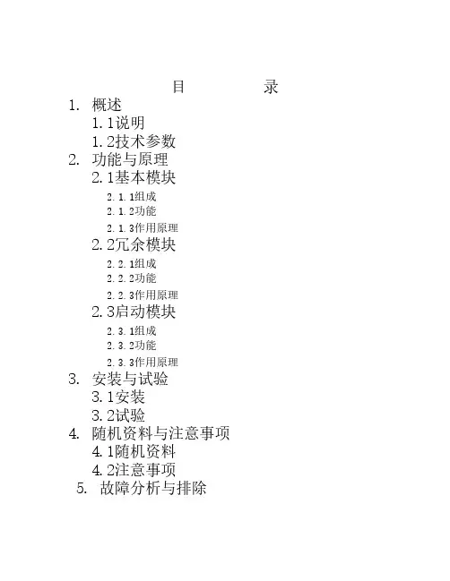
目 录1. 概述1.1说明1.2技术参数2. 功能与原理2.1基本模块2.1.1组成2.1.2功能2.1.3作用原理2.2冗余模块2.2.1组成2.2.2功能2.2.3作用原理2.3启动模块2.3.1组成2.3.2功能2.3.3作用原理3. 安装与试验3.1安装3.2试验4. 随机资料与注意事项 4.1随机资料4.2注意事项5. 故障分析与排除1.概述1.1说明速关控制装置是汽轮机保安系统和控制系统的集合。
它将原来该系统中单个部套组合在一起。
这样,克服了管路繁多、安装复杂的缺陷,在运行中也避免了监控困难和产生漏油着火的事故,增加了汽轮机运行可靠性和安全性。
速关控制装置能实现汽轮机正常启动与停机、电动与手动紧急停机、速关阀和危急遮断器自动挂钩。
为了增加安全性,速关控制装置还设置了电动紧急停机的冗余系统。
以上功能分别由基本模块、冗余模块、启动模块来实现。
1.2 技术参数1.2.1 液压参数油源压力 0.8MPa (0.6~1.2MPa)工作介质 透平油 32# 46#过滤精度 ≤40μm液体温度 10~70℃1.2.2 电参数电源电压24VDC(1±10%)1.2.3 环境温度 -20~80℃1.2.4 保护种类 IP65(不防爆)EExd11cT4(防爆)用户在订货时必须注明保护种类。
2.功能与原理2.1 基本模块2.1.1 组成手动停机阀 (2274)电磁阀 (2225)停机卸荷阀 (2030)调节油切换阀 (2050)速关阀在线试验阀(1845)2.1.2 功能手动紧急停机电动紧急停机速关阀在线试验2.1.3 作用原理高压油从“P”进入基本模块,在基本模块壳体内分为五路。
第一路经手动停机阀(2274)和电磁阀(2225)进入停机卸荷阀 (2030),克服弹簧力使阀处于关闭状态。
正常运行时,通向停机卸荷阀的速关油不泄油。
速关油是由冗余模块内部管路引入的。
第二路油经调节油切换阀(2050)变为调节控制油经冗余模块内部管路进入启动模块成为电液转换器供油。
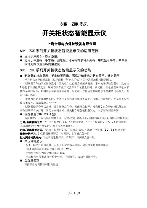
SHK―ZXK系列开关柜状态智能显示仪上海合凯电力保护设备有限公司SHK―ZXK系列开关柜状态智能显示仪的适用范围■适用于户内3~35kV系统;■适用于中置柜、手车柜、固定柜、环网柜等多种开关柜,用以显示手车、断路器、接地刀闸位置及柜内温湿度。
SHK―ZXK系列开关柜状态智能显示仪的功能■断路器的状态显示、手车位置显示、隔离刀和接地刀状态显示、储能显示开关柜状态智能显示仪(以下简称“智能显示仪”)的一次系统模拟图见图1。
断路器手车处于工作位置时,发光柱1红色垂直模拟条发光;手车处于试验位置时,发光柱1绿色水平模拟条发光;断路器手车位于试验和工作位置之间时,发光柱1红色垂直和绿色水平模拟条同时闪烁;断路器手车移出开关柜时,发光柱1红色垂直和绿色水平模拟条均不发光,表示手车已断电。
接地刀闸处于合闸状态时,发光柱3红色竖直模拟条发光;接地刀闸断开时,发光柱3绿色模拟条发光,表示接地刀闸分闸。
断路器处于合闸状态时,其常开节点闭合、常闭节点打开,发光柱2红色竖直模拟条发光;断路器常开节点打开、常闭节点闭合时,发光柱2绿色模拟条发光,表示断路器已分闸。
■操控装置(SHK-ZXK-4型)面板带有:分闸/合闸转换开关;远方/就地转换开关;储能转换开关;柜内照明转换开关。
分闸/合闸转换开关:“分闸”位置时3-4、7-8触点接通,“合闸”位置时,1-2、5-6触点接通,当自动恢复到“0”状态时,所有节点全部断开。
远方/就地转换开关:“远方”位置时3-4、7-8触点接通,“就地”位置时,1-2、5-6触点接通。
储能转换开关:3位长柄选择开关,有常开、常闭触点各一组。
柜内照明转换开关:2位长柄选择开关,有常开、常闭触点各一组。
■高压带电显示当A、B或C相带电时,面板上相应的指示灯亮,同时提供带电闭锁接点。
LED启动电压为额定相电压的15~65%。
闭锁启控电压为额定相电压的65%。
当三相同时带电或有一相带电时,闭锁灯亮,启动电磁锁动作。
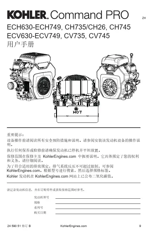
24 590 51 修订 B ZH9ECH630-ECH749, CH735/CH26, CH745用户手册重要提示:设备操作前请阅读所有安全预防措施和说明。
请参阅安装该发动机设备的操作说明。
执行任何保养或检修前请确保发动机已停机并平坦放置。
保修范围在保修卡及 中扼要说明。
它具体规定了您的权利和义务,请仔细阅读。
为了符合适用的排放规定,排气系统反压不可超过限制,可参阅 。
根据型号进行搜索,然后选择规格标签。
Kohler 发动机在 网站上已公布二氧化碳值。
请记录发动机信息,并在订购零件或获取保修范围时参考。
发动机型号规格系列号购买日期ECV630-ECV749, CV735, CV74524 590 51 修订 B 10易爆炸的燃油可能引起火灾和严重灼伤。
在发动机处于高温或运转时,切勿往燃油箱内加油。
汽油很容易燃烧,且它的蒸气被点燃的时候易爆炸。
存警告高温零件可能引起严重灼伤。
切勿在运转期间或停机后立即触摸发动机。
在发动机防热罩或隔热板拆走后,切记不能运行发动机。
警告旋转零件可能引起严重人身伤害。
切记远离运转中的发动机。
手、足、头发和衣物必须远离正在转动的零件以防人身伤害。
在外盖、保护罩或防护装置拆走的时候,不要运行发动机。
警告意外起动可能造成严重人身伤害甚至死亡。
在维护前请断开火花塞导线并将其接地。
在发动机或设备上工作之前,请按以下说明停止发动机:1)断开火花塞导线。
2) 断开电池的负极 (–) 电池线。
警告一氧化碳可能导致严重呕吐、昏厥甚至死亡。
避免吸入排放的尾气。
切勿在室内或密闭空间内运行发动机。
发动机排放的尾气含有有毒的一氧化碳。
一氧化碳是无味、无色的气体,且吸入过多时会导致死亡。
警告: 可能导致死亡、严重人身伤害或重大财产损失的危险。
告诫:可能导致轻微人身伤害或财产损失的危险。
注意: 用于告知人们非常重要的发动机安装、操作或保养相关信息。
高压液体可能刺破皮肤,并造成严重人身伤害甚至死亡。

BT-GLKZ-2x系列微电脑锅炉控制器(电开水)使用说明书一、概述BT-GLKZ-2x系列智能锅炉控制器吸收国外先进技术,结合国内锅炉自动化的需求,采用单片微电脑控制技术而推出的新一代全自动小型锅炉通用控制器,适用于燃油∕燃气、燃煤、生物质燃料、电加热的蒸汽锅炉,热水锅炉,开水锅炉的自动控制。
本控制器具有可靠性强、自动化程度高、使用操作简便、造型新颖美观、显示信息丰富直观,性价比高等优点。
本说明适用于电加热开水锅炉。
二、主要技术指标2.1 输入⏹三个水位电极检测。
⏹一路热保有源开关量输入(常闭,断开有效)。
⏹炉水温度输入信号检测,测量精度1%F.S显示分辨率1℃量程0-120℃。
2.2 输出⏹两路220V∕16A输出容量(补水泵,循环泵)⏹四路220V∕8A输出容量(加热组)。
2.3 显示方式⏹ 3.5寸超大高亮彩色LCD显示屏。
2.4 使用条件⏹电源:交流220V ±10%(50Hz)。
⏹功耗:≤8W。
⏹工作环境:环境温度0~45℃相对湿度≤85%。
⏹外型尺寸:高×宽×深=215×158×70 mm。
⏹开孔尺寸:高×宽=185+1×129.6+1 mm。
三、基本操作3.1 参照对应炉型接线图正确接线,接通电源。
3.2关机状态下,按电源键,控制器打开,蜂鸣器鸣叫一声,显示屏点亮,控制器自检3秒后进入待机状态。
3.3 待机状态按运行键,屏幕右上角系统状态显示“运行”,控制器按所选控制要求运行。
3.4 运行状态按运行键,屏幕右上角系统状态显示“待机”,控制器切换到待机状态。
3.5 运行状态下,按电源键,关闭控制器,显示器熄灭。
四、键功能4.1 电源键: 开启∕关闭控制器显示屏。
4.2 运行键: 切换运行∕待机状态。
4.3 设置键:待机和运行状态下,点按一下,进入密码界面。
密码界面:确认密码正确,点按进入参数;密码不正确,点按退出密码界面。

KPZ系列带式输送机用盘式制动装置使用说明书(执行标准:QB/GX013-2009)邹城市广信科技开发有限责任公司地址:邹城市经济开发区西外环路1888号邮编:273500电话:************传真:0537-*******E-mail:*********************出版日期:2009年05月28日目录1.2.3.结构特征与工作原理4.5.6.使用与操作7.故障分析与排除8.9.10.11.1.系统概述1.1用途KPZ系列液压盘式制动装置主要用于大型机电设备的可控制动停车:(1)下运带式输送机的制动和停车装置;(2)上运带式输送机的制动和停车装置;(3)其它设备的制动装置;1.2适用条件(1)环境温度-20℃~55℃,(2)无显著摇摆和剧烈振动、冲击的场合;(3)无足以锈蚀金属的气体和尘埃的环境;(4)无滴水、漏水的地方。
1.3产品特点KPZ系列带式输送机用盘式制动装置(以下简称盘式制动装置)主要用于下运带式输送机的制动。
盘式制动装置用于下运带式输送机,其解决了制动盘散热及制动火花问题,实现了带式输送机软制动并符合《煤矿安全规程》规定。
能有效地防止超速、飞车事故的发生。
盘式制动装置用于上运特别是大倾角上运输送机,使输送机更安全、可靠,能有效防止逆止器失效而出现的倒飞车事故。
1.4型号组成及其代表意义K P Z ——制动力矩(N.m)制动盘直径(mm)制动盘形式(Ⅰ、Ⅱ、Ⅲ)矿用盘式制动器1.5产品组成盘式制动装置由本体、液压站、电控箱、连接油管等组成。
2.技术特性2.1主要性能(1)能有效地防止输送机超速。
通过测速元件实际反映输送机带速,超速时可实施工作制动或安全制动。
(2)正常停车功能。
与电控系统配套,使输送机在规定的减速度(0.1-0.3m/s2)下停车。
(3)故障停车功能。
自动检测输送机运行状态,故障时自动停车。
(4)突然停车功能。
系统突然失电可使输送机平稳停车。
(5)电控系统配置手动功能,方便了设备调试,并确保输送机在电控箱自身故障时仍能起车,满足生产急需。

DTZZIII-QX-Z 系列起重量限制器使用说明书V2.1.2.1.0一、技术参数及型号型号QX-Z1QX-Z2QX-Z4主要特点⒈触点输出⒉配双传感器⒊所配传感器安装于升降机导轨托架与吊笼吊耳连接处⒈触点输出⒉所配传感器安装于升降机导轨托架与吊笼吊耳连接处⒊配载荷显示模块⒈触点输出⒉配单传感器(带支架)⒊所配传感器安装于升降机固定支架上技术参数电源AC220(-15~+10%)V精度 1.0级灵敏度<0.1%控制回差<1%工作温度-10~60℃仪器功耗<10W传感器过载能力150%输出触点容量2A/DC24V;2A/AC220V产品共性1.产品所配传感器安装方式不同,详见四;2.产品的输入信号接线方式均相同,详见二;3.产品输出继电器均为一动开一动闭;4.产品安装方式均相同,详见三、四;5.QX-Z2配带载荷显示模块,具体端子功能详见二。
二、限制器外形尺寸及端子功能限制器外形尺寸图根据客户需要可选配载荷显示模块如下图所示,其作用是通过RS485通讯与限制器相连可实时显示吊笼内实际载重量,限制器与载荷显示模块之间通讯线的长度应小于1km。
载荷显示模块各端子功能如下:1、2:电源DC15V,其中1接限制器端子5(DC15V+),2接限制器端子9(GND);3、4:485通讯,其中3接限制器端子8(B),4接限制器端子7(A)。
三、限制器的安装尺寸及安装方法a、控制柜安装b、限制器安装配件尺寸限制器安装尺寸图如果限制器直接安装在升降机控制柜中,可以用M6的螺栓,按照图a直接将限制器安装在控制柜里面;如果需要安装在别的地方,可以将两个安装附件(图b所示)固定在机箱后面(图a的两个M6螺纹),之后再将限制器安装配件固定到需要的位置。
四、传感器的安装⒈轴销式传感器安装于升降机导轨托架与吊笼吊耳连接处。
传感器安装图注:⒈传感器必须和控制仪配套使用,不得单独使用(单独使用后如出现任何问题,我公司不承担责任)。
VK型电动弹簧操作机构使用说明广州东芝白云电器设备有限公司1. VK 型真空断路器的使用方法1-1构造图1至是各部分的名称和示意图。
图1储能手柄插入口 分合闸指示 (合闸—红色、分闸—绿色)控制回路二次插座 抽出推入摇柄插入口技术规格 计数器储能指示(白色:释能、黄色:储能)合闸按钮分闸按钮1-2 手动操作方法(1)储能操作如图6所示,插入储能手柄,上下摇动数次(通常约7次)后会听到“喀喳”的声音。
这时,合闸弹簧储能指示由“白色(DISCHARGED)”变成“黄色(CHARGED)”,显示进入储能状态。
储能手柄插入口图 6分闸按钮储能指示合闸按钮分合闸指示图7(2)合闸操作按下合闸按钮(CLOSING BUTTON),断路器闭合。
这时,分合闸指示显示“CLOSED”,储能指示显示“白色(DISCHARGED)”。
(3)分闸操作按下分闸按钮(TRIP BUTTON),断路器分闸。
这时,分合闸指示显示“OPEN”。
!注意以下操作会造成断路器故障:1 在合闸状态下按合闸按钮。
2 在按着分闸按钮的状态下,按合闸按钮。
3 在提起右侧联锁提杆的状态下,按合闸按钮。
1-3电动操作方法(1)储能操作连接好断路器的控制回路,并接通电源后,电动机立即转动,合闸弹簧开始储能。
当储能指示的显示由“白色”(DISCHARGED)变为“黄色”(CHARGED)后,合闸弹簧储能完毕。
(2)合闸操作发出合闸指令后,合闸线圈励磁,断路器合闸。
合闸后电动机继续转动,直到合闸弹簧储能完成为止。
分合闸指示显示“CLOSED”。
合闸弹簧储能指示显示黄色的“CHARGED”。
(3)分闸操作发出分闸指令后,分闸线圈劢磁,断路器分闸。
分合闸指示显示“OPEN”。
2.断路器动作说明!注意不要在卸下面板的情况下操作断路器。
以免发生灾害、事故。
2.1 控制回路的动作(1)合闸动作合闸弹簧储能完毕后,断路器如果处于分闸状态,其控制回路如图2a。
在此状态下,如果接通(合)CS1,在b,Y-b,X-b的回路上,合闸线圈励磁的瞬间(约50ms),断路器合闸。
谷夫道Pungo双Z轴控制系统版本号V1.0操作手册安全须知本节叙述有关CNC装置使用的安全预防措施。
用户必须遵守这些预防措施以保证配置有CNC的机床的安全操作,这是非常重要的。
注意有些预防措施只与一些特定的功能相关,因此对某些CNC装置是不可用的。
操作者还必须遵守由机床厂商提供的说明书中指明的与机床有关的安全预防措施。
操作者必须在完全熟悉本说明书以及由制造厂商提供的相关说明书的内容后,才能操作机床或编制程来控制机床。
一般的警告和注意1.零件加工前,一定要首先检查机床的正常运行。
加工前,一定要通过连续仿真保证机床正确工作。
例如利用单段执行,进给倍率,或手轮引导等,且在机床上不装工件和刀具时检查机床的正确运行。
如果未能确认机床动作的正确性,机床可能出现错误动作,有可能损坏工件、机床或伤害用户。
2.操作机床之前,请仔细地检查输入的数据。
如果使用了不正确的数据,机床可能错误动作,有可能引起工件的损坏、机床本身的损坏或使用户受伤。
3.确保指定的进给速度与想要进行的机床操作相适应。
通常,每一台机床都有最大许可进给速度。
合适的进给速度根据不用的操作而变化。
请参阅机床厂提供的说明书来确定最大的进给速度。
如果没有按正确的速度进行操作,机床有可能发生错误动作,从而引起工件或机床本身的损坏,甚至伤及用户。
4.当使用刀具补偿功能时,请仔细检查补偿方向和补偿量。
使用不正确的指定数据操作机床,机床可能发生错误动作,从而引起工件或机床本身的损坏,甚至伤及用户。
C内部的参数都是机床厂设置的,通常不需要修改,当必须修改参数的时候,请确保改动参数之前对参数的功能有深入全面的了解。
如果不能对参数进行正确的设置,有可能引起机床的错误动作,可能损坏工件、机床本身或伤害用户。
6.在软件启动以后,请不要随意触碰键盘上的键。
键盘上很多键被指定为软件的快捷键,按下这些键,可能使机床处于某种状态。
7.本说明书叙述的某些功能,对特定机床实际上并不适用。
1数控机床说明书刘子琪1.1 本说明书的有用范畴与目标本说明书是为指导用户精确应用我公司临盆的平床身数控车床而编写的,请用户卖力扫瞄。
在本说明书的第2部分,供给了操作机床的安稳须知,操作者能够把它作为日常工作的检查条目。
在本说明书的第3部分“吊运与安装”中供给了安装本机床的方法和应留意的事项。
在本说明书的第4部分“技巧参数”和第5部分“机床构造”中介绍了操作本机床预先应当明白得的内容。
第6部分“机床的应用和安稳防护”介绍了机床操作中安稳方面的防护情形。
第7部分“检查与修理”中为操作者供给了操作和修理本机床所须要的常识和方法。
第8部分“易损件”中供给了机床的易损件的简图。
假如显现本说明书未能涵盖的情形,请与我公司售后办事部分或技巧部分接洽。
1.2 产品的重要用处本机床重要用于加工各类轴类、盘类零件,能够车削各类螺纹、圆弧、圆锥及反转展转体的表里曲面,能够或许知足黑色金属及有色金属材料高速切削的速度需求。
合适于水暖器材、阀门、电器、外表、汽车、摩托车、轴承等行业零件的加工。
具有高速、高效、高靠得住性,加工零件一致性好、受工资身分阻碍小等的长处。
加工精度可达到IT 6~IT 7级。
1.3 机床的精度本机床的精度相符JB/T8324.1-1996《简式数控卧式车床精度》的标准的要求。
1.4 机床的应用情形本机床合适鄙人述规定的情形和前提下运行:■情形空气温度:5℃~40℃范畴内。
■湿度:最高温度40℃下,相对湿度不得跨过50%的的范畴内,且温度变更的原则是不克不及引起冷凝。
■海拔高度:1000米以下。
■大年夜气污染:没有过分的粉尘、酸气等腐化性气体和盐分。
■辐射:幸免阳光直射或其他热辐射引起情形温度的变更。
■安装地位应远离振动源和易燃易爆物品,远离电磁干扰区。
1.5 机床对情形的阻碍本机床空运转时噪声声压级不大年夜于83dB,无有害气体或液体排放,是以对情形无不良阻碍。
2 安稳防护须知本机床带有一些须要的安稳设备和警示标牌,请操作者在开机前细心扫瞄说明书,完全明白得机床应用方法,清晰警示标牌含义后再上机操作,以防止显现操作人员损害或设备毁伤的变乱。