Power Electronics Laboratory in a Box(中英)
- 格式:doc
- 大小:724.00 KB
- 文档页数:3

电气工程及其自动化专业英语介绍Introduction to Electrical Engineering and its Automation1. IntroductionElectrical Engineering and its Automation is a specialized field that combines the principles of electrical engineering with automation technology. It focuses on the design, development, and implementation of electrical systems and their automation for various applications in industries, power generation, communications, and transportation.2. CurriculumThe curriculum of Electrical Engineering and its Automation program is designed to provide students with a strong foundation in electrical engineering principles, automation technology, and practical skills. The courses typically include:2.1 Electrical Engineering Courses- Circuit Theory: This course introduces the fundamental concepts of electrical circuits, including Ohm's Law, Kirchhoff's Laws, and circuit analysis techniques.- Electromagnetic Field Theory: Students learn about the behavior of electromagnetic fields and how they interact with electrical systems.- Power Systems: This course covers the generation, transmission, and distribution of electrical power, as well as power system protection and control.- Digital Electronics: Students study the principles of digital logic circuits and learn to design and analyze digital systems.- Control Systems: This course focuses on the theory and techniques used in the design and analysis of control systems.2.2 Automation Technology Courses- Programmable Logic Controllers (PLCs): Students learn about the programming and application of PLCs, which are widely used in industrial automation.- Industrial Robotics: This course introduces the principles and applications of industrial robots in manufacturing processes.- Human-Machine Interface (HMI): Students study the design and development of user-friendly interfaces for interacting with automated systems.- Industrial Networks: This course covers the communication protocols and network architectures used in industrial automation.3. Laboratory FacilitiesThe Electrical Engineering and its Automation program provides state-of-the-art laboratory facilities to enhance practical learning and research opportunities for students. These facilities include:3.1 Electrical Circuits Laboratory: Equipped with various electrical components and instruments, this lab allows students to conduct experiments related to circuit analysis, electrical measurements, and troubleshooting.3.2 Automation Laboratory: This lab provides hands-on experience with programmable logic controllers, industrial robots, and human-machine interfaces.3.3 Power Systems Laboratory: Students can simulate and analyze power system operations, protection schemes, and control strategies using advanced software tools.4. Career ProspectsGraduates of the Electrical Engineering and its Automation program have diverse career opportunities in various industries, research institutions, and government organizations. Some potential career paths include:4.1 Electrical Engineer: Graduates can work as electrical engineers, involved in the design, installation, and maintenance of electrical systems in industries such as power generation, telecommunications, and transportation.4.2 Automation Engineer: With expertise in automation technology, graduates can work as automation engineers, responsible for designing and implementing automated systems in manufacturing and process industries.4.3 Control Systems Engineer: Graduates can pursue careers as control systems engineers, involved in the design and optimization of control systems for industrial processes and machinery.4.4 Research and Development: Graduates can also pursue research and development roles, working on advanced technologies and innovations in electrical engineering and automation.5. ConclusionThe Electrical Engineering and its Automation program offers a comprehensive education in electrical engineering principles and automation technology. With a strong theoretical foundation and practical skills, graduates are well-equipped to contribute to the advancement of industries and society through the design and implementation of innovative electrical systems and automation solutions.。

PGElectrical · Principle of Function · Universal Gripper1044Modular RoboticsModular-Standardized interfaces for mechatronics and control for rapid and simple assembly without complicated designs-Cube geometry with diverse possibilities for creating individual solutions from the modular systemIntegrated-The control and power electronics are fully integrated in the modules for minimal space requirements and interfering contours-Single-cable technology combines data transmission and the power supply for minimal assembly and start-up costs Intelligent-Integrated high-end microcontroller for rapid data processing -Decentralized control system for digital signal processing -Universal communication interfaces for rapid incorporation in existing servo-controlled conceptsYour advantages and benefitsThe modules of the PowerCube series provide the basis for flexible combinatorics in automation. Complex systems and multiple-axis robot structures with several degrees of freedom can be achieved with minimum time and expenditure spent on design and programming.Module overviewThe innovative technology of the PowerCube modules already forms the basis of numerous applications in the fields of measuring and testing systems, laboratory automation, service robotics and flexiblerobot technology.PGServo-electric2-Finger Parallel Gripper PRServo-electric Rotary Actuators PWServo-electricRotary Pan Tilt ActuatorsPSMServo-motors with integrated position controlPDUServo-positioning motor with precision gearsPLSServo-electric Linear Axes withball-and-screw spindle drivePG·Universal Gripper1045Method of actuationThe PowerCube modules work completely independently. The master control system is only required for generating the sequential program and sending it step by step to the connected modules. Therefore, only the current sequential command is ever stored in the modules, and the subsequent command is stored in the buffer. The current, rotational speed and positioning are controlled in the module itself. Likewise, functions such as temperature and limit monitoring are performed in the module itself. Real-time capability is not absolutely essential for the master control or bus system. For the communication over Bus-System the SMP - SCHUNK Motion Protocol - is used. This enables you to create industrial bus networks,and ensures easy integration in control systems.Control version AB Hardware Control with PLC (S7)Control with PC Interface Profibus DP CAN bus / RS-232SoftwareWindows (from Windows 98) operating systemLINUX operating systemDevelopment platforms MC-Demo Operating Software PowerCube (LabView, Diadem)with Online documentation, standard softwaregsd-file, programming examples(gsd file, programming examples)on requeston requestIncluded with the ''Mechatronik DVD'' (ID 9949633): Assembly and Operating Manual with manufacturer's declaration, MCDemo software and description and gsd-file for S7 use.1234567889ᕃ24VDC / 48VDC power supply provided by the customerᕄControl system provided by the customer (see control versions A, B and C)ᕅPAE 130 TB terminal block for connecting the voltage supply, the communication and the hybrid cable (Option for easy connection)ᕆPDU servo-motorᕇLinear axis with PLS ball-and-screw spindle drive and PSM servo-motorᕈHybrid cable (single-cable technology) for connecting the PowerCube modules (voltage supply and communication). Not recommended for the use in Profibus applications ᕉPW Servo-electric Rotary Pan Tilt Actuator ᕊPG Servo-electric 2-Finger Parallel Gripper ᕋPR Servo-electric Rotary ActuatorPG· Universal Gripper1046Size 70Weight 1.4 kg Gripping force up to 200 N Stroke per finger 35 mm Workpiece weight1 kgApplication exampleDouble rotary gripper module for loading and unloading of sensitive componentsPG 70 Servo-electric 2-Finger Parallel Gripper PR 70 Servo-electric Rotary ActuatorPGUniversal Gripper1047Gripping force control in the range of 30 - 200 N for the delicate gripping of sensitive workpieces Long stroke of 70 mm for flexible workpiece handlingFully integrated control and power electronics for creating a decentralized control systemVersatile actuation optionsfor simple integration in existing servo-controlled concepts via Profibus-DP, CAN bus or RS-232Standard connecting elements and uniform servo-controlled conceptfor extensive combinatorics with other PowerCube modules (see explanation of the PowerCube system)Single-cable technology for data transmission and power supplyfor low assembly and start-up costsServo-electric 2-finger parallel gripper with highly precise gripping force control and long strokeUniversal GripperArea of applicationUniversal, ultra-flexible gripper for great part variety and sensitive components in clean working environmentsYour advantages and benefitsGeneral information on the seriesWorking principle Ball screw driveHousing materialAluminum alloy, hard-anodized Base jaw materialAluminum alloy, hard-anodized ActuationServo-electric, by brushless DC servo-motorWarranty 24 monthsScope of deliveryGuide centering sleeves and ‘’Mechatronik DVD’’ (contains an Assembly and Operating Manual with manufacturer’s declarartion and MC-Demo software withdescription)PG· Universal Gripper1048Control electronicsintegrated control and power electronics for controlling the servo-motorEncoderfor gripper positioning and position evaluationDrivebrushless DC servo-motorGear mechanismtransfers power from the servo-motor to the drive spindleSpindletransforms the rotational movement into the linear movement of the base jaw Humidity protection cap link to the customer’s systemThe brushless servo-motor drives the ball screw by means of the gear mechanism.The rotational movement is transformed into the linear movement of the base jaw by base jaws mounted on the spindles.Function descriptionThe PG gripper is electrically actuated by the fully integrated control and power electronics. In this way, the module does not require any additional external control units.A varied range of interfaces, such as Profibus-DP, CAN-Bus or RS-232 are available as methods of communication. For the communication over Bus-System the SMP - SCHUNK Motion Protocol - is used. This enables you to create industrial bus networks, and ensures easy integration in control systems.If you wish to create combined systems (e.g. a rotary gripper module), various other modules from the Mechatronik-Portfolio are at your disposal.Electrical actuationSectional diagramPGUniversal Gripper1049Gripping forceis the arithmetic total of the gripping force applied to each base jaw at distance P (see illustration), measured from the upper edge of the gripper.Finger lengthis measured from the upper edge of the gripper housing in the direction of the main axis.Repeat accuracyis defined as the spread of the limit position after 100 consecutive strokes.Workpiece weightThe recommended workpiece weight is calculated for a force-type connection with a coefficient of friction of 0.1 and a safety factor of 2 against slippage of theworkpiece on acceleration due to gravity g. Considerably heavier workpiece weights are permitted with form-fit gripping.Closing and opening timesClosing and opening times are purely the times that the base jaws or fingers are in motion. Control or PLC reaction times are not included in the above times and must be taken into consideration when determining cycle times.General information on the seriesCentering sleevesElectrical accessories PAE terminal blockPAM standardconnecting elementsAccessoriesHybrid cableFor the exact size of the required accessories, availability of this size and the designation and ID, please refer to the additional views at the end of the size in question. You will find more detailed information on our accessory range in the …Accessories“ catalog section.PG 70· Universal Gripper1050Technical dataFinger loadMoments and forces apply per base jaw and may occur simultaneously. M y may arise in addition to the moment generated by the gripping force itself. If the max.permitted finger weight is exceeded, it is imperative to throttle the air pressure so that the jaw movement occurs without any hitting or bouncing. Service life may bereduced.Gripping force, I.D. grippingDescriptionPG 70Mechanical gripper operating data ID 0306090Stroke per finger [mm]35.0Constant gripping force (100 % continuous duty)[N]200.0Max. gripping force [N]200.0Min. gripping force [N]30.0Weight [kg] 1.4Recommended workpiece weight [kg] 1.0Closing time [s] 1.1Opening time [s] 1.1Max. permitted finger length [mm]140.0IP class20Min. ambient temperature [°C] 5.0Max. ambient temperature [°C]55.0Repeat accuracy [mm]0.05Positioning accuracy [mm]on request Max. velocity [mm/s]82.0Max. acceleration [mm/s 2]328.0Electrical operating data for gripper Terminal voltage [V]24.0Nominal power current [A] 1.8Maximum current [A] 6.5Resolution [µm] 1.0Controller operating data Integrated electronics Yes Voltage supply [VDC]24.0Nominal power current [A]0.5Sensor system EncoderInterfaceI/O, RS 232, CAN-Bus, Profibus DPPG 70Universal Gripper1051ᕃ24 VDC power supply provided by thecustomerᕄControl (PLC or similar) provided bythe customerᕅPAE 130 TB terminal block(ID No. 0307725) for connecting the power supply, the communication and the hybrid cableᕆHybrid cable for connecting thePowerCube modulesMain viewsThe drawing shows the gripper in the basic version with closed jaws, the dimensions do not include the options described below.ᕃGripper connection ᕄFinger connectionᕓᕗM16x1.5 for cable glandActuation DescriptionID Length PowerCube Hybrid cable, coiled 03077530.3 m PowerCube Hybrid cable, coiled03077540.5 mPowerCube Hybrid cable, straight (per meter)9941120The ‘Hybrid cable’ is recommended for the use in CAN-Bus- or RS232-systems. For Profibus applications we recommend to use a separate standardized Profibus cable for the communication.You can find further cables in the …Accessories“ catalog section.Interconnecting cablePG 70· Universal Gripper1052Special lengths on requestRight-angle standard element for connecting size 70 PowerCube modulesSpecial lengths on requestConical standard element for connecting size 70 and 90 PowerCube modulesSpecial lengths on requestStraight standard element for connecting size 70 PowerCube modules Right-angle connecting elements Description ID DimensionsPAM 120030782090°/70.5x98Conical connecting elements Description ID DimensionsPAM 110030781090x90/45/70x70 mm PAM 111030781190x90/90/70x70 mmStraight connecting elements Description ID DimensionsPAM 100030780070x70/35/70x70 mm PAM 101030780170x70/70/70x70 mmMechanical accessoriesYou can find more detailed information and individual parts of the above-mentioned accessories in the …Accessories“ catalog section.。

部分工厂常用英文,供大家参考部分工厂常用英文,供大家参考.Education and Training教育训练proposal improvement/creative suggestion提案改善BS Brain Storming 脑力激荡QCC Quality Control Circle 品质圈PDCA Plan Do Check Action 计划执行检查总结DCC delivery control center 交货管制中心3CComputer 计算机类产品Consumer electronics 消费性电子产品Communication 通讯类产品7SClassification整理(sorting, organization)-seiriRegulation整顿(arrangement, tidiness)-seiton Cleanliness清扫(sweeping, purity)-seisoConservation清洁(cleaning, cleanliness)-seiktsuCulture教养(discipline)-shitsukeSave 节约Safety安全质量人员名称类QC quality control 品质管理人员FQC final quality control 终点质量管理人员IPQC in process quality control 制程中的质量管理人员OQC output quality control 最终出货质量管理人员IQC incoming quality control 进料质量管理人员TQC total quality control 全面质量管理POC passage quality control 段检人员QA quality assurance 质量保证人员OQA output quality assurance 出货质量保证人员QE quality engineering 质量工程人员质量保证类FAI first article inspection 新品首件检查FAA first article assurance 首件确认CP capability index 能力指数CPK capability process index 模具制程能力参数SSQA standardized supplier quality audit 合格供货商质量评估FMEA failure model effectiveness analysis 失效模式分析FQC运作类AQL Acceptable Quality Level 运作类允收质量水平S/S Sample size 抽样检验样本大小ACC Accept 允收REE Reject 拒收CR Critical 极严重的MAJ Major 主要的MIN Minor 轻微的Q/R/S Quality/Reliability/Service 质量/可靠度/服务P/N Part Number 料号L/N Lot Number 批号AOD Accept On Deviation 特采UAI Use As It 特采FPIR First Piece Inspection Report 首件检查报告PPM Percent Per Million 百万分之一制程统计品管专类SPC Statistical Process Control 统计制程管制SQC Statistical Quality Control 统计质量管理GRR Gauge Reproductiveness & Repeatability 量具之再制性及重测性判断量可靠与否DIM Dimension 尺寸DIA Diameter 直径N Number 样品数其它质量术语类QIT Quality Improvement Team 质量改善小组ZD Zero Defect 零缺点QI Quality Improvement 质量改善QP Quality Policy 目标方针TQM Total Quality Management 全面质量管理RMA Return Material Audit 退料认可7QCTools 7 Quality Control Tools 品管七大手法通用之件类ECN Engineering Change Notice 工程变更通知(供货商)ECO Engineering Change Order 工程改动要求(客户)PCN Process Change Notice 工序改动通知PMP Product Management Plan 生产管制计划SIP Standard Inspection Procedure 制程检验标准程序SOP Standard Operation Procedure 制造作业规范IS Inspection Specification 成品检验规范BOM Bill Of Material 物料清单PS Package Specification 包装规范SPEC Specification 规格DWG Drawing 图面系统文件类ES Engineering Standard 工程标准CGOO China General PCE龙华厂文件IWS International Workman Standard 工艺标准ISO International Standard Organization 国际标准化组织GS General Specification 一般规格部类PMC Production & Material Control 生产和物料控制PCC Product control center 生产管制中心PPC Production Plan Control 生产计划控制MC Material Control 物料控制DC Document Center 资料中心QE Quality Engineering 质量工程(部)QA Quality Assurance 质量保证(处)QC Quality Control 质量管理(课)PD Product Department 生产部LAB Laboratory 实验室IE Industrial Engineering 工业工程R&D Research & Design 设计开发部生产类PCs Pieces 个(根,块等)PRS Pairs 双(对等)CTN Carton 卡通箱PAL Pallet/skid 栈板PO Purchasing Order 采购订单MO Manufacture Order 生产单D/C Date Code 生产日期码ID/C Identification Code (供货商)识别码SWR Special Work Request 特殊工作需求L/N Lot Number 批号P/N Part Number 料号OEM Original Equipment Manufacture 原设备制造PC Personal Computer 个人计算机CPU Central Processing Unit 中央处理器A.S.A.P As Soon As Possible 尽可能快的E-MAIL Electrical-Mail 电子邮件N/A Not Applicable 不适用QTY Quantity 数量I/O input/output 输入/输出NG Not Good 不行,不合格C=0 Critical=0 极严重不允许APP Approve 核准,认可,承认CHK Check 确认ASS'Y Assembly 装配,组装T/P True Position 真位度5WIH When, Where, Who, What, Why, How to6M Man, Machine, Material, Method, Measurement, Message4MTH Man, Material, Money, Method, Time, How 人力,物力,财务,技术,时间(资源) SQA Strategy Quality Assurance 策略质量保证DQA Design Quality Assurance 设计质量保证MQA Manufacture Quality Assurance 制造质量保证SSQA Sales and service Quality Assurance 销售及服务质量保证LRR Lot Reject Rate 批退率SPS Switching power supply 电源箱DT Desk Top 卧式(机箱)MT Mini-Tower 立式(机箱)DVD Digital Video DiskVCD Video Compact DiskLCD Liquid Crystal DisplayCAD Computer Aided DesignCAM Computer Aided ManufacturingCAE Computer Aided EngineeringPCB Printed Circuit Board 印刷电路板CAR Correction Action Report 改善报告NG Not Good 不良WDR Weekly Delivery Requirement 周出货要求PPM Percent Per Million 百万分之一TPM Total Production Maintenance 全面生产保养MRP Material Requirement Planning 物料需计划OS Operation System 操作系统TBA To Be Assured 待定,定缺D/C Drawing ChangeP/P Plans & ProcedureEMI Electrical Magnetic Interference 电子干扰RFI Read Frequency Input 读频输入MMC Maximum Material ConditionMMS Maximum Material SizeLMC Least Material ConditionLMS Least Material SizeLED lighting-emitting diode 发光二极管QBR Quarter Business RecordCIP Continuous improvement processFGI Forecasted Goal InventoryCNC Computerized numeral controllerB2C Business to customerB2B Business to businessAVL Approved vendor listPOP Procedure of packagingEOL End of lifeVDCS Vender defect correcting sheetPDCS Process defect correcting sheetGRN Goods receiving noteA/R Accounting receivableA/P Accounting payable三:专业词汇通用类president董事长operator作业员position职务general manager总经理special assistant 特助deputy manager |'depjuti| =vice manager副理deputy supervisor =vice supervisor副课长group leader组长line leader线长supervisor 课长responsible department负责单位Human Resources Department人力资源部Head count 人头数production department生产部门QC Section品管课administration/general affairs dept./总务部production unit生产单位meeting minutes会议记录distribution department分发单位subject主题conclusion结论decision items决议事项pre-fixed finishing date预定完成日Color management 颜色管理Visual management 目视管理production capacity生产力first count初盘first check初盘复棹second count 复盘second check复盘复核quantity of physical inventory second count 复盘点数量physical inventory盘点数量physical count quantity账面数量difference quantity差异量spare parts physical inventory list备品盘点清单cause analysis原因分析waste materials废料description品名specification 规格model机种work order工令revision版次remark备注registration登记registration card登记卡to control管制application form for purchase请购单consume, consumption消耗to notify通知to fill in填写to collect, to gather收集statistics统计cosmetic inspection standard 外观检验规范computer case 计算机外壳(组件)personal computer enclosure 计算机机箱产品front plate前板rear plate后板chassis |'∫æsi| 基座bezel panel面板Hood 上盖base pan 基座bezel 面板flat cable 排线resin film 树脂膜raw materials原料materials物料steel plate钢板roll/coil material卷料spare parts =buffer备品plastic parts塑料件sheet metal parts/stamping parts 冲件material check list物料检查表finished product成品semi-finished product半成品good product/accepted goods/ accepted parts/good parts良品defective product/non-good parts不良品disposed goods处理品warehouse/hub仓库packing material包材basket蝴蝶竺plastic basket胶筐flow chart流程窗体production tempo生产进度现状lots of production生产批量manufacture procedure制程to revise, modify修订to switch over to, switch—to, switching over切换engineering bottleneck, project difficulty工程瓶颈glove(s)手套glove(s) with exposed fingers割手套Band-Aid创可贴Industrial alcohol工业酒精broom扫把mop拖把vacuum cleaner吸尘器rag 抹布garbage container灰箕garbage can垃圾箱garbage bag垃圾袋liaison联络单rags抹布lamp holder灯架to mop the floor拖地to clean a table擦桌子air pipe 气管delivery deadline交货期die worker模工production, to produce生产equipment设备resistance电阻beacon警示灯coolant冷却液crusher破碎机plate电镀power button电源按键reset button重置键forklift叉车Workshop traveler 天车trailer =long vehicle拖板车Hydraulic trolley手压车hydraulic hand jack油压板车casing = containerization装箱velocity速度patent专利coordinate坐标supply and demand供求career card履历卡barricade隔板carton box纸箱to pull and stretch拉深work cell/work shop工作间sub-line支线bottleneck 瓶颈packaging tool打包机packaging打包品质类qualified products, up-to-grade products良品defective products, not up-to-grade products不良品defective product box不良品箱poor processing 制程不良poor incoming part来件不良exposed metal/bare metal金属裸露excessive defect过多的缺陷critical defect极严重缺陷major defect主要缺陷minor defect次要缺陷not up to standard不合规格cosmetic defect外观不良lack of painting烤漆不到位slipped screw head/slippery slipped thread滑丝missing part漏件wrong part错件oxidation氧化defective threading抽芽不良poor staking铆合不良deficient purchase来料不良deficient manufacturing procedure制程不良cosmetic inspection外观检查inner parts inspection内部检查blister 气泡angular offset 角度偏差dent 压痕scratch 刮伤deformation 变形filings 铁削defective label 不良标签abrasion 磨损Breaking. (be)broken,(be)cracked 断裂short射料不足nick缺口speck瑕疪shine亮班splay 银纹gas mark焦痕delaminating起鳞speckle斑点mildewed =moldy = mouldy发霉deformation变形burr(金属)flash(塑件)毛边poor staking铆合不良excessive gap间隙过大grease/oil stains油污inclusion杂质shrinking/shrinkage缩水mixed color杂色fold of packaging belt打包带折皱painting make-up补漆discoloration羿色water spots水渍impurity 杂质Mismatch 错位failure, trouble 故障deformation 变形rust 生锈peel 脱漆Shrink 缩水Contamination 脏污water spots 水渍Gap 间隙label error 标签错误Missing label 漏贴rejection criteria 拒收标准Suspected rejects 可疑庇abrasion 损伤、磨损Texture surface 印花纹表面Streak 条纹stains 污点Blotch 斑点discoloration 脱色Inclusion 杂质slug mark 压痕dirt grime 灰尘blush 毛边薄膜sink 下凹Hickey 漏漆labels and logos 贴纸与商标Configuration labels 组合贴纸corrugated container 瓦摆纸箱Delaminating 脱层splattering 散点Gouge 锉孔puckering 折痕烤漆类phosphate皮膜化成viscosity涂料粘度alkalidipping脱脂main manifold主集流脉organic solvent有机溶剂demagnetization去磁;消磁high-speed transmission高速传递heat dissipation热传rack上料volatile挥发性degrease脱脂rinse水洗alkaline etch龄咬desmot剥黑膜D.I. rinse纯水次Chromate铬酸处理Anodize阳性处理seal封孔scraped products报放品disposed products处理品dismantle the die折模auxiliary function辅助功能heater band 加热片thermocouple热电偶derusting machine除锈机degate打浇口dryer烘干机induction感应induction light感应光response =reaction =interaction感应ram连杆edge finder巡边器concave凸convex凹cold slug冷块blush 导色gouge沟槽;凿槽satin texture段面咬花witness line证示线grit沙砾granule =pellet =grain细粒sand blasting喷沙grit maker抽粒机cushion缓冲fillet镶;嵌边roller pin formality滚针形式cam driver铡楔shank摸柄crank shaft曲柄轴组装类Assembly line组装线Layout布置图Conveyer流水线运输带Rivet machine拉钉机Rivet gun拉钉枪Screw driver起子Electric screw driver电动起子Hydraulic machine 液压机Pneumatic screw driver气动起子automation自动化to stake, staking, riveting铆合add lubricant oil加润滑油argon welding氩焊cylinder油缸robot机械手conveying belt输送带transmission rack输送架to draw holes抽孔bolt螺栓nut 螺母screw 螺丝identification tag标示单screwdriver plug起子插座automatic screwdriver电动启子to move, to carry, to handle搬运be put in storage入库packing包装staker = riveting machine铆合机fit together组装在一起fasten锁紧(螺丝)fixture 夹具(治具)pallet/skid栈板barcode条形码barcode scanner条形码扫描仪fuse together熔合fuse machine/heat stake热熔机processing, to process加工delivery, to deliver 交货to return delivery to. to send delivery back to return of goods退货easily damaged parts易损件standard parts标准件to lubricate润滑spring 弹簧spare tools location/buffer手工备品仓spare molds location模具备品仓tox machine自铆机waste废料board广告牌sliding rack滑料架to impose lines压线to compress, compressing压缩character die字模to feed, feeding送料material change, stock change材料变更feature change 特性变更prepare for, make preparations for 准备rotating speed, revolution转速abnormal handling异常处理工厂常用缩略语5S:5S管理ABC:作业制成本制度(Activity-Based Costing)ABB:实施作业制预算制度(Activity-Based Budgeting)ABM:作业制成本管理(Activity-Base Management)APS:先进规画与排程系统(Advanced Planning and Scheduling) ASP:应用程序服务供货商(Application Service Provider)ATP:可承诺量(Available To Promise)BOM:物料清单(Bill Of Material)BPR:企业流程再造(Business Process Reengineering)BSC:平衡记分卡(Balanced ScoreCard)BTF:计划生产(Build To Forecast)BTO:订单生产(Build To Order)CPM:要径法(Critical Path Method)CRM:客户关系管理(Customer Relationship Management)CRP:产能需求规划(Capacity Requirements Planning)CTO:客制化生产(Configuration To Order)DBR:限制驱导式排程法(Drum-Buffer-Rope)DRP:运销资源计划(Distribution Resource Planning)DSS:决策支持系统(Decision Support System)EC:设计变更/工程变更(Engineer Change)EC:电子商务(Electronic Commerce)EDI:电子资料交换(Electronic Data Interchange)EIS:主管决策系统(Excutive Information System)EOQ:基本经济订购量(Economic Order Quantity)ERP:企业资源规划(Enterprise Resource Planning)FMS:弹性制造系统(Flexible Manufacture System)FQC:成品品质管制(Finish or Final Quality Control)IPQC:制程品质管制(In-Process Quality Control)IQC:进料品质管制(Incoming Quality Control)JIT:实时管理(Just In Time)KM:知识管理(Knowledge Management)L4L:逐批订购法(Lot-for-Lot)LTC:最小总成本法(Least Total Cost)LUC:最小单位成本(Least Unit Cost)MES:制造执行系统(Manufacturing Execution System)MPS:主生产排程(Master Production Schedule)MRP:物料需求规划(Material Requirement Planning)MRPⅡ:制造资源计划(Manufacturing Resource Planning)OEM:委托代工(Original Equipment Manufacture)ODM:委托设计与制造(Original Design & Manufacture)OLAP:线上分析处理(On-Line Analytical Processing)OLTP:线上交易处理(On-Line Transaction Processing)OPT:最佳生产技术(Optimized Production Technology)OQC:出货品质管制(Out-going Quality Control)PDCA:PDCA管理循环(Plan-Do-Check-Action)PDM:产品数据管理系统(Product Data Management)PERT:计画评核术(Program Evaluation and Review Technique)POH:预估在手量(Project on Hand)QCC:品管圈(Quality Control Circle)RCCP:粗略产能规划(Rough Cut Capacity Planning)ROP:再订购点(Re-Order Point)SCM:供应链管理(Supply Chain Management)SFC:现场控制(Shop Floor Control)SIS:策略信息系统(Strategic Information System)SPC:统计制程管制(Statistic Process Control)TOC:限制理论(Theory of Constraints)TQC:全面品质管制(Total Quality Control)TQM:全面品质管理(Total Quality Management)WIP:在制品(Work In Process)>>> 5S:5S管理5S是由JP企业研究出来的一种环境塑造方案,其目的在藉由整理(SEIRI)、整顿(SEITON)、清扫(SEISO)、清洁(SEIKETSU)及身美(SHITSUKE)五种行为来创造清洁、明朗、活泼化之环境,以提高效率、品质及顾客满意度。

浙江省慈溪市2025届高三英语12月适应性考试试题留意事项:1.本试卷分第I卷(选择题)和第II卷(非选择题);全卷满分150分,考试时间120分钟。
2答题前,考生务必把自己的姓名、准考证号填写在答题卡上。
3.答第I卷时,用2B铅笔把答题卡上对应题目的答案标号涂黑、涂满;如需改动,用橡皮擦干净后,再选涂其它答案标号。
4.答第II卷时,用黑色墨水钢笔在答题卡规定区域内作答;答在本试卷上或超出答题区域书写的答案无效。
第I卷第一部分:听力(共两节,满分30分)第一节(共5小题;每小题1.5分,满分7.5分)听下面5段对话。
每段对话后有一个小题,从题中所给的A、B、C三个选项中选出最佳选项,并标在试卷的相应位置。
听完每段对话后,你都有10秒钟的时间来回答有关小题和阅读下一小题。
每段对话仅读一遍。
例:How much is the shirt?A. £19.15.B. £9.18C. £9.15答案是C。
1. How many times has the woman been to China?A. Once.B. Twice.C. Three times.2. How much will the man have to pay in all?A. $60.B. $70.C. $80.3. What is the woman probably going to do?A. Perform a concert.B. Give a speech.C. Practice singing4. What does the woman most probably do?A. A secretary.B. A coach.C. A manager.5. Where does the woman advise the man to go for a job?A. At a shop.B. At a school.C. At a factory.其次节(共15小题;每小题1.5分,满分22.5分)听下面5段对话或独白。

1rf/microwave instrumentation“A ”Series.DC to 400 MHz.25 to 10,000 watts.“W” Series.DC to 1000 MHz.1to 4000 watts.Distributed T ube Amplifier 10 kHz to 100 MHz.10,000 watts.RF Power Amplifiersfor EMC and General RF Testing2009/2010E s t a b l i s h e d 1981AR began in 1969 with just two men in a cellar, moonlighting from their regular jobs.Don (“Shep”) Shepherd and his partner, Dan Roth, worked for AEL (American Electronics Laboratories),producing radio frequency design for military applications. They saw a market for their skills in designing amplifiers for test applications, but AEL was not set up for such jobs. So they decided to try and make it on their own, working out of a makeshift laboratory in Shep’s cellar.1969 – We sold our first amplifier for a total of $600 (including $60 for special connectors).1970 – Moved out of Shep’s cellar and up to small rented storefront. 1972 – Distribution expands into Europe.1973 – Amplifier Research (AR) moves to new headquarters at160 School House Rd. in Souderton, PA.1976 – AR introduces first 10,000 watt tube amplifier (10 kHz -100 MHz). It’s still available,and there’s still no equal.1979 – Company passes $1 million in sales.1987 – 75 employees now work for AR.1988 – First 100 watt solid-state, 100-1000 MHzinstantaneous bandwidth amplifier built.It weighed 215 lbs. and was 29.3" high.1990 – Second building completed at headquarters. Sales exceed $10 million.1992 – AR unveils first 500 watt solid-state amplifier (100 -1000 MHz).1994 – A third building is erected at 160 School House Rd.1996 – AR reaches $25 million in sales with 100 employees.2001 – The company expands it capabilities into amplifier modulesand customized systems with the acquisition of Kalmus in Bothell, WA, now AR Modular RF .Back in Souderton, a fourth building is completed. Sales exceed $35 million.“We started the company in my basement.Because the only place we could go from there was up.”Don Shepherd, Founder2002 – Carnel Labs in Canoga Park, CA joins the AR family,becoming AR Receiver Systems.2003 – First 10,000 watt / 100 kHz - 250 MHz solid-state amplifier forautomotive/military/avionics testing created. Still the only 10,000 watt solid state available.2004 –The little company that started in a cellar now has 125 employees.2005 – New engineering department and microelectronics lab (clean room) open.Sales pass the $45 million mark.2006 – New 15,000 sq. ft. building is completed at corporate headquarters withexpanded production facilities to meet the ever-growing demand for AR products.150 employees now work for AR.2007– AR introduces first 10-20 GHz / 5 watt instantaneous bandwidth test amplifier.2009– AR celebrates 40 years in business.AR, which now encompasses AR RF/Microwave Instrumentation, AR Modular RF ,AR Receiver Systems and AR Europe, employs over 200 people and continues to lead the industry with innovative, superior quality, technologically-advanced products and a global support system that’s second to none.We definitely have risen far from Shep’s cellar.21Folding back is typical of Class AB and lesser-grade Class A designs. AR’s Class A circuitry is built to higher standards:All “Class A”Is Not The Same.• AR uses tandem push-pull transistor pairs. This arrangement is more rugged than the single output devices found in lesser grade Class A amplifiers.• AR amplifiers use internal power combiners that can withstand high reflected power.• AR amplifiers use only top quality, high-power internal directional couplers • AR amplifiers use switching power supplies to increase efficiency and reduce internal heat load.It’s no wonder that only AR claims and delivers 100% rated power to the load!“We Started With A Dream,And It’s Grown Into A Reality.”T oday we’re recognized as the ultimate source for testing and communications solutions in the worlds of EMC,military, wireless, and beyond. And our products are everywhere.They’re boosting the power of military radios for our troops in battle; driving the most sophisticated industrial/medical/scientific equipment; testing the emissions and susceptibility of electronic equipment; and helping new electronic products get to market faster.We’ve become the industry leader by continually setting the bar a little higher.By raising quality.And increasing cost-efficiency.With innovations like “subampability” – the ability to add power to existing amps; and test systems that can be upgraded from the Internet to adapt to changing specs.With the combined resources of all the AR companies, AR is your source for everything from RF power amplifiers,antennas, complete test systems, probes, monitors, software and receivers to military booster amps, and RF amplifier modules that can be customized to meet the toughest specs.We take great pride in the support & service we deliver to our customers anywhere in the world, whenever they need it.Infinite VSWR T olerance Means More P ower T o Y ou.Approximately 80% of the amplifiers in this brochure are completely immune to load VSWR. That means 100% of the power is delivered to the load 100% of the time. Our highest power amplifiers refuse to limit until VSWR exceeds 6.0:1 or 50% (of rated output) reflected power. Competitive Class AB amplifiers respond to reflected power from high VSWR by limiting output power at the exact time you need every bit of power. Some actually shut down. We find that completely unacceptable .Donald “Shep” Shepherd Chairman430The Difference Is Power Delivered T o The Load.Since the output power of AR amplifiers does not fold back with VSWR, more power is absorbed in the load.The Difference Is Several Times Greater.Most AR amplifiers do not fold back or limit. The power absorbed by the load is many times greater than with competitive amplifiers that fold back at 1/VSWR.and one controller/combiner, you get 3000watts of power;and so on up to 4000 watts.The amplifiers can still be used independently when tests call for less power.See Application Note #40A Expandable Power for further details.W e design our amplifiers not just for today, but for tomorrow. Most models include:• Digital Control Panels (DCP) in one of two formats: graphical vacuum fluorescent or two-line vacuum fluorescent• Built-in IEEE-488 Interface and RS-232interface (Fiberoptic RS-232 on Graphical DC • Local and Remote Control (on DCP amplifier)• Forward and Reflected Power Readout (on graphical DCPs)• Control Status and Internal Amplifier Status Reports• USB and Ethernet – on selected models See individual amplifier spec sheets to verify the features on any amplifier.Expandable PowerRF test levels are constantly increasing. The same is true for many test distances. Usually, this requires larger, more powerful amplifiers. It also means throwing out your old amps. But AR is changing all that.Many amplifiers in our “S” and “W” Series allow you to add power to existing amps as needed. There’s no need to toss out a perfectly good amp and start all over again. W e call this concept “Subampability .”Much like building blocks, it enables you to add incremental power using existing amps. With arelatively simple upgrade, you can “combine” multiple amps to achieve the power you need. This is clearly an idea whose time has come.But it gets even better.Since the higher power would be needed only for some tests, “Subampability” enables you to split the amplifiers so that they can be used individually whenever needed.Here’s an example of how “Subampability” works: If you start with a 1000W1000C amplifier (1000 Watts CW , 80-100 MHz) and then you need more power,you can add another 1000W1000C amplifier and a controller/combiner for 2000 watts of power.And you can keep going!With three 1000W1000C amplifiersGood Enough Isn’t Good Enough.So W e Keep T weaking.Ready For The Future.Subampability™: (sub-amp-ability). noun: The ability to use an amplifier individually , or as a building block, upon which powercan be added incrementally .Solid State, Low Frequency Amplifiers.W e’re constantly under the cover of our amplifierstweaking the major components and making improvements. After years of R&D, AR has perfected the technology of optimal module performance. The result is increased bandwidth and more power, especially at the high end of the frequency range.T wo modules, one from 100 kHz to 250 MHz and one from 100 kHz to 400 MHz, offer this new technology. These modules serve as basic building blocks for the 10,000A250A and 5000A250Aamplifiers, as well as for the 100A400 and 150A400amplifiers for BCI applications.The need for higher power is continually increasing; and AR is ready. Our new “A” Series amplifiers feature 500, 1000, and 2500-watt models with expanded coverage down to 10 kHz.And we’re now able to pack more power into smaller “packages.”6AR Competitive Edge products supply a multitude of unique RF solutions to companies around the world. The company’s limitless support network reaches the far corners of the globe. AR products are backed by the company’s“Competitive Edge” warranty, the best and most comprehensive warranty in the industry.When companies purchase from any AR company they have the peace of mind that comes from knowing the global leader will be there to help with any problems today, tomorrow and always.A Global Support Network That’s Second T o None.A warranty is only as good as the company and the people behind it. AR’s highly-trained,experienced support staff is the best in the business.And they are right where you need them, in all the far corners of the globe. Help is just a phone call away… today, tomorrow and always.See “Sales Associates” at for a complete listing or call Customer Service at 215-723-0275.By the way, when you call,you’ll talk to a real receptionist who will connect you to the help you need. Y ou can also call our hotline at 800-933-8181 and talk to directly an applications engineer whose job is to help one person at a time.V alue Right From The Start… a 10% Bonus.AR’s quality makes our products a good value.But we also help you save right up front. When you visit the AR booth at a trade show, you’ll receive a bonus coupon that’s worth 10% of the purchase price of your AR amplifier toward the purchase of any AR accessory. That’s anything other than amplifiers–and it’s good for up to $20,000!Quality, V alue, Service and Innovation That No Other Company Can Match.With the combined resources of all the AR companies, AR is your source for everything from power amplifiers, antennas, complete test systems,probes, monitors, software and receivers to amplifier modules that can be customizedto meet the toughest specs.5The Most Comprehensive And Most Meaningful W arranty In The Industry.A Better Amplifier And A Better V alue. W att For W att, Our Amplifiers Cost Less!Lower cost doesn’t necessarily equal a better value.Not when you’re paying for power that you never get.The following equation will help you calculate the per-watt cost of your amplifier and the dollar-for-dollar value:Consider a typical 100 watt AR Class A amplifier driving a high VSWR (100 watt output, 50% or 50 watts reflected at 6.0:1 and 50 watts absorbed by the load) at a cost of $20,000–Compare this with a competitive 100 watt Class AB amplifier also driving a high VSWR (due to foldback, only 34 watts output, 50% or 17 watts reflected at 6.0:1 and 17 watts absorbed by the load) at a cost of $15,000–These numbers clearly demonstrate that while the initial cost of AR amplifiers may be higher, the net result based on superior performance is greater value. In other words, our amplifiers provide more bang for the buck!$20,00050W= $400/watt$15,00017W= $882/wattAmplifier PricePower Absorbed by the Load= Amplifier Price Per Watt40AD140 watts CW. dc-1 MHz.Rated Output Power40 watts Input For Rated Output 1.0 milliwatt max.350AH1350 watts CW. 10 Hz - 1 MHz.Operation Class AB LinearPower Output(1.79 Ohm load)75A40075 watts CW. 10 kHz-400 MHz.Rated Output Power75 watts min.Input For Rated Output 1.0 milliwatt max.1500A31500 watts CW. 10 kHz-3 MHz.Rated Output Power1500 wattsInput For Rated Output 1.0 milliwatt max.5000A35000 watts CW. 10 kHz-3 MHz.Rated Output Power5000 wattsInput For Rated Output 1.0 milliwatt max.800A3A800 watts CW. 10 kHz-3 MHz.Rated Output Power800 wattsInput For Rated Output 1.0 milliwatt max.25A250A25 watts CW. 10 kHz-250 MHz. Rated Output Power25 watts Input For Rated Output 1.0 milliwatt max.75A250A75 watts CW. 10 kHz-250 MHz.Rated Output Power75 wattsInput For Rated Output 1.0 milliwatt max.100A250A100 watts CW. 10 kHz-250 MHz.Rated Output Power100 wattsInput For Rated Output 1.0 milliwatt max.500A250A500 watts CW. 10 kHz-250 MHz.Rated Output Power500 wattsInput For Rated Output 1.0 milliwatt max.1000A2251000 watts CW. 10 kHz-225 MHz.Rated Output Power1000 wattsInput For Rated Output 1.0 milliwatt max.2500A2252500 watts CW. 10 kHz-225 MHz.Rated Output Power2500 watts, 10 kHz - 50 MHz2500 - 1900 watts, 50 MHz - 225 MHz150A100B150 watts CW . 10 kHz-100 MHz.Rated Output Power 150 watts Input For Rated Output 1.0 milliwatt max.150A220150 watts CW . 10 kHz-220 MHz.Rated Output Power 150 watts min.Input For Rated Output 1.0 milliwatt max.3500A100A3500 watts CW .10 kHz-100 MHz.Rated Output Power 3500 watts Input For Rated Output 1.0 milliwatt max.10,000L10,000watts CW .10 kHz-100MHz.Rated Output Power Nominal 12,600 watts 100A400100 watts CW . 100 kHz-400 MHz.Rated Output Power 100 watts min.Input For Rated Output 1.0 milliwatt max.150A400150 watts CW . 100 kHz-400 MHz.Rated Output Power 150 watts min.Input For Rated Output 1.0 milliwatt max.5000A250A5000 watts CW.100 kHz-250MHz. Rated Output Power5000 watts, 100 kHz - 100 MHz5000 - 3000 watts, 100 MHz - 250 MHz Input For Rated Output 1.0 milliwatt max.10000A250A10,000watts CW.100kHz-250MHz.Rated Output Power10,000 watts, 100 kHz - 100 MHz10,000 - 6,000 watts, 100 MHz - 250 MHz1W1000B1 watt CW. 100 kHz-1000 MHz.Rated Output Power 1.0 watts min.Input For Rated Output 1.0 milliwatt max.10W1000C10 watts CW. 500 kHz-1000 MHz.Rated Output Power10 watts min.Input For Rated Output 1.0 milliwatt max.30W1000B30 watts CW. 1-1000 MHz.Rated Output Power30 watts min.Input For Rated Output 1.0 milliwatt max.150A250150 watts CW. 100 kHz-250 MHz. Rated Output Power150 watts min. Input For Rated Output 1.0 milliwatt max.250W1000A250 watts CW. 80-1000 MHz. Rated Output Power250 watts min. Input For Rated Output 1.0 milliwatt max.500W1000A500 watts CW. 80-1000 MHz.Rated Output Power525 watts min.Input For Rated Output 1.0 milliwatt max.1000W1000C1000 watts CW. 80-1000 MHz.Rated Output Power1000 watts min.Input For Rated Output 1.0 milliwatt max.100W1000B100 watts CW. 1-1000 MHz. Rated Output Power100 watts Input For Rated Output 1.0 milliwatt max.150W1000150 watts CW. 80-1000 MHz. Rated Output Power150 watts Input For Rated Output 1.0 milliwatt max.50W1000B50 watts CW. 1-1000 MHz. Rated Output Power50 watts min. Input For Rated Output 1.0 milliwatt max.3000W10003000 watts CW. 80-1000 MHz. Rated Output Power2800 watts min. Input For Rated Output 1.0 milliwatts max.4000W10004000 watts CW. 80-1000 MHz.Rated Output Power3600 watts min.Input For Rated Output 1.0 milliwatts max.10WD100010 watts CW. dc-1000 MHz.Rated Output Power15 watts min.Input For Rated Output 1.0 milliwatt max.50WD100050 watts CW. dc-1000 MHz.Rated Output Power50 watts min.Input For Rated Output 1.0 milliwatt max.2000W1000A2000 watts CW. 80-1000 MHz. Rated Output Power1900 watts min. Input For Rated Output 1.0 milliwatts max.40AD1– DC - 1 MHz1000W1000C – 80 MHz - 1 GHz250W1000A – 80 MHz - 1 GHz350AH1 – 10 Hz - 1 MHz150A400 – 100 kHz - 400 MHz150A250– 100 kHz - 250 MHz150A220 – 10 kHz - 220 MHz100A250A – 10 kHz - 250 MHz50WD1000– DC - 1 GHz50W1000B – 1 MHz - 1 GHz30W1000B – 1 MHz - 1 GHz10WD1000– DC - 1 GHz10W1000C – 500 kHz - 1 GHz1W1000B – 100 kHz - 1 GHz25A250A 10 kHz - 250 MHz75A250A – 10 kHz - 250 MHz500A250A –10 kHz - 250 MHz150W1000 – 80 MHz - 1 GHz 500W1000A – 80 MHz - 1 GHz800A3A – 10 kHz -3 MHz1500A3 – 10 kHz -3 MHz1000A225 – 10 kHz - 225 MHz2000W1000A – 80 MHz - 1 GHz2500A225 – 10 kHz - 225 MHz3000W1000 – 80 MHz - 1 GHz3500A100A –10 kHz - 100 MHz4000W1000 – 80 MHz - 1 GHz5000A250A – 100 kHz - 250 MHz5000A3 – 10 kHz -3 MHz10,000A250A – 100 kHz - 250 MHz10,000L – 10 kHz - 100 MHz75A400– 10 kHz - 400 MHz100W1000B – 1 MHz - 1 GHz150A100B – 10 kHz - 100 MHzO U T P U T P O W E R (W A T T S )11010253040505075751001001001501501501501502503505005008001k 1k 1.5k 2k 2.5k 3k 3.5k 4k 5k 5k 10k 10k15801002003004005006007008009001000500100FREQUENCYFREQUENCY1920100A400 – 100 kHz - 400 MHza r RF/Microwave Instrumentationa r Modular RFa r Receiver Systemsa rEuropea rrf/microwave instrumentation •modular rf •receiver systems •ar europe© Copyright 2009 AR AR5694–7.5Ma rRF/Microwave Instrumentationa rModular RFa r Receiver Systemsa rEurope。
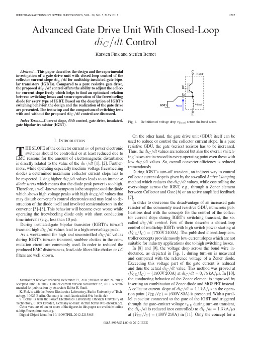
Advanced Gate Drive Unit With Closed-Loopdi C/dt ControlKarsten Fink and Steffen BernetAbstract—This paper describes the design and the experimental investigation of a gate drive unit with closed-loop control of the collector current slope di C/dt for multichip insulated-gate bipo-lar transistors(IGBTs).Compared to a pure resistive gate drive, the proposed di C/dt control offers the ability to adjust the collec-tor current slope freely which helps tofind an optimized relation between switching losses and secure operation of the freewheeling diode for every type of IGBT.Based on the description of IGBT’s switching behavior,the design and the realization of the gate drive are presented.The test setup and the comparison of switching tests with and without the proposed di C/dt control are discussed.Index Terms—Current slope,di/dt control,gate drive,insulated-gate bipolar transistor(IGBT).I.I NTRODUCTIONT HE SLOPE of the collector current i C of power electronic switches should be controlled or at least reduced due to EMC reasons for the amount of electromagnetic disturbance is directly related to the value of the di C/dt[1],[2].Further-more,while operating especially medium-voltage freewheeling diodes a determined maximum collector current slope has to be ing higher di C/dt values leads to an immense diode stress which means that the diode peak power is too high. Therefore,a well-known symptom is the snappiness of the diode which shows high voltage peaks with high dv CE/dt values that may disturb converter’s control electronics and may lead to de-struction of the diode itself and involved semiconductors in the converter[3]–[5].This behavior will become even worse while operating the freewheeling diode only with short conduction time intervals(e.g.,less than10μs).During insulated-gate bipolar transistor(IGBT)’s turn-off transient high di C/dt values lead to a high overvoltage peak. As a workaround for high and uncontrolled di C/dt values during IGBT’s turn-on transient,snubber chokes in the com-mutation circuit are commonly used.In order to reduced the produced EMC disturbances,load-sidefilters like chokes or LC filters are well known.Manuscript received received December27,2011;revised March24,2012; accepted June18,2012.Date of current version November22,2012.Recom-mended for publication by Associate Editor E.Santi.K.Fink is with the Power Electronics Laboratory,Berlin University of Tech-nology,10623Berlin,Germany(e-mail:karsten.fink@tu-berlin.de).S.Bernet is with the Power Electronics Laboratory,Dresden University of Technology,01069Dresden,Germany(e-mail:steffen.bernet@tu-dresden.de). Color versions of one or more of thefigures in this paper are available online at .Digital Object Identifier10.1109/TPEL.2012.2215885Fig.1.Definition of voltage drop v B on d across the bond wires.On the other hand,the gate drive unit(GDU)itself can beused to reduce or control the collector current slope.In a pureresistive GDU,the gate(series)resistor has to be increased.Thus,the di C/dt values are reduced but also the overall switch-ing losses are increased in every operating point even these withlow di C/dt values.So,overall converter efficiency is reducedtremendously.During IGBT’s turn-off transient,an indirect way to controlcollector current slope is given by the so-called Active Clampingmethod which reduces the di C/dt values,while controlling theovervoltage across the IGBT,e.g.,through a Zener elementbetween Collector and Gate[6]or an active amplified feedback[7].In order to overcome the disadvantage of an increased gateresistor of the commonly used resistive GDU,numerous pub-lications deal with the concepts for the control of the collec-tor current slope during IGBT’s switching transient,the so-called di C/dt control.Few of them describe a closed-loopcontrol of multichip IGBTs with high switch power starting at(V CE/I C)=(1700V2400A).The published closed-loop con-troller concepts provide mostly low-current slopes which are notsuitable for industry applications due to high switching losses.In[8]and[9],the voltage drop across the bond wire in-ductance,as depicted in Fig.1,during turn-on is measuredand compared with the reference voltage of a Zener diode.Exceeding this voltage part of the gate current is reducedand thus the actual di C/dt value.This method was proved at(V CE/I C)=(1500V200A)at di C/dt=0,75kA/μs.In[10],the conducting behavior of the Zener element is improved byinserting an combination of Zener diode and MOSFET instead.A collector current slope of di C/dt=1.1kA/μs in the opera-tion point(V CE/I C)=(600V80A)is presented.With a paral-lel capacitor connected to the gate of the IGBT and triggeredthrough the gate–emitter voltage v GE during turn-on transient,the di C/dt is reduced(not controlled)to di C/dt=1.3kA/μsat(V CE/I C)=(400V250A)in[11].Only the concept for a 0885-8993/$31.00©2012IEEEclosed-loop control of the collector current slope di C/dt is pre-sented in[12].Here,the bond wire voltage drop is activelymeasured as the actual value for the control loop.Unfortu-nately,the author discards this solution for it will not be suitablefor modern high-power IGBT modules.Very promising is theconcept published in[13]and[14]which describes aflexibledi C/dt control adapted to the realization with an application-specific integrated circuit.With this,the actual di C/dt valueis measured via the bond wire inductance again,and the re-sulting collector current slope can be chosen almost free.Forthe proposed circuit is based on current mirrors,the amplifica-tion factor is limited thus the maximum gate current value.So,only IGBTs with low nominal currents can be controlled by theGDU.The behavior of the circuit is proved with a di C/dt up todi C/dt=0,08kA/μs at(V CE/I C)=(600V20A).In[15],acircuit based on fast operational amplifiers(OPs)is used forthefirst time to control the di C/dt of IGBTs during turn-onand turn-off with the same collector current slope.The conceptis proved at(U CE/I C)=(300V1000A)with an adjustabledi C/dt up to1.3kA/μs.Summarizing the presented state-of-the-art leads the motiva-tion of an advanced GDU with a control of the collector currentslope for multichip IGBTs.The designated features of a closed-loop di C/dt control are as follows:1)the GDU is suitable for high-power multichip IGBTs,i.e.,high drive power is available;2)independent di C/dt reference values are possible for turn-on and turn-off transient,e.g.,the di C/dt controller canbe deactivated for turn-off transients;3)easy to parametrize circuit based on OPs are realizedwhich could be partly digitized later on;4)freely adjustable di C/dt values are possible;5)GDU generates the current slope reference value by itsown and needs only the turn-on/turn-off signal(calledPulse in the following).This paper presents a proposal for a di C/dt control schemefor the turn-on transient of the IGBT.II.T URN-O N BEHA VIOR OF THE IGBTDuring the turn-on transient,the IGBT crosses several periodswhich determine its behavior based on various semiconductorequations[1],[5],[16].Fig.2shows thefive periods schemati-cally.The determining period for the di C/dt is t E,1≤t<t E,2. Here,the gate current i G can be described with(1)where thecurrent into the MOSFET of the equivalent circuit of the IGBTis almost zeroi G=C GE·dv GEdt−C GC·d(v CE−v GE)dt+i MOS.(1)The relation of the transconductance g fs in(2)is valid during the whole transientg fs=dI CdV GE≈I CV GE−V GE,th.(2)The fact that the gate–collector capacitance C GE is negligibly small at high collector–emitter voltage values v CE leads to(3),Fig.2.di C/dt period(gray background)during turn-on transient of theIGBT. Fig.3.Structure of di C/dt control for IGBT’s turn-on transient.(The limiter[≥0]blanks negative di C/dt values,thus the turn-off transient.)respectively,(4)di Cdt=g fs·dv GEdt(3)⇒di Cdt=g fsC GE·i G.(4)Equation(4)shows that for a constant collector current slope, the product g fs·i G has to be constant.So,a di C/dt controller should only adjust the change in the transconductance g fs during the current rise.III.C ONTROL CONCEPTAssuming the designated features in Section I,the proposed GDU with di C/dt control is based on the structure depicted in Fig.3.For high-power IGBT modules have a bond wire inductance L Bond about10nH,its voltage drop v Bond is taken due to(5) as a measure for the actual di C/dt value as in other concepts in the literaturev Bond=−L Bond·di Cdt.(5)FINK AND BERNET:ADV ANCED GATE DRIVE UNIT WITH CLOSED-LOOP di C /dt CONTROL 2589The reference value v ref ,di/dt for the di C /dt controller which is generated by the switching command can be described byνref ,di /dt =S ·A di/dt .(6)The sign and the amplitude of the bond wire voltage v Bond is changed before the signal is led to limiter which lets only positive di C /dt signals pass through.This means that only the di C /dt value of the turn-on transient is controlled.The collector current slope of the turn-off transient is only limited by the gate resistor R G as usual in a resistive gate drive.The difference of the actual and the reference value is led to the P-controller with its amplification factor P di/dt before it is amplified in voltage (and current)by the power stage with P ES .For all signals in the controller circuit are realized in a ±10V level,due to the linear area of the used OP-amps,the power has to bring it to the ±15-V gate voltage level of high-power IGBTs and additionally provides the necessary drive power.The resulting control voltage v G is thereby given byv G =P ES ·P di/dt · νref ,di /dt +v Bond D di/dt ≥0.(7)Replacing the bond wire voltage in (7)by the actual collector current slope in (5)leads the complete equation of the di C /dt control loop during a turn-on transientv G =P ES ·P di/dt ·νref ,di /dt −L Bond D didt ·di C dt ≥0 .(8)It is important nevertheless that for every reference valueνref ,di/dt ,the static on-and off-state voltage ±15V of the IGBT is respected so that it can be operated safely.Therefore,for ev-ery reference value,a minimum amplification value P di/dt,min of the P-controller is required and can be calculated by (9)with the voltage amplification factor of the power stage P ESP di/dt,min =15VP ES·u ref ,di /dt.(9)The realization of the concept is described in Section V .IV .S YSTEM SIMULATIONSIn order to evaluate the dynamic behavior of the proposed control scheme,numerous simulations are done.In this process,a dynamic model of an IGBT with corresponding freewheeling diode is investigated in a buck converter topology,as depicted in Fig.4.The concept for the IGBT model of the Infineon FS450R17KE3is taken from [17]and [18].Additionally,pa-rameters of the PSpice-based model are adapted reflecting the dynamic behavior of the Infineon FS450R17KE3in reference measurements.The resulting PSpice-model consists of three IGBT and diode chip models,each packed in an impedance matrix calculated by FastHenry .1For electronic simulations on device level in a power electronic application,a PSpice simulator is necessary which can handle the fast dynamic change of power electronic devices like IGBTs.So,SIMetrix was chosen [19].1FastHenry is a free distributed program for inductance analysis by the Com-putational Prototyping Group of the MIT.Also seewww.fastfiFig.4.Simulation circuit for investigation of the functionality of the di C /dt controlscheme.Fig. 5.Simulated waveforms of turn-on transient of the Infineon FS450R17KE3with di C /dt control at (V C E /I C )=(500V 450A )with R G =0,5Ωand various reference values νref ,d i /d t =1...6V ( =di C /dt =0,28...2,07kA /μs ).For the first step,the control loop behavior was programmed in PSpice language in order to investigate the functionality of the overall concept.The Code is given in Code 1in the Appendix.Thus,the behavior of the proposed di C /dt control can be simulated.The resulting waveforms of the di C /dt controlled gate drive with various reference values at a dc-link voltage of V DC =500V and a switch current of I C V =500are depicted in Fig.5.2590IEEE TRANSACTIONS ON POWER ELECTRONICS,VOL.28,NO.5,MAY2013Fig. 6.Simulated waveforms of turn-on transient of the Infineon FS450R17KE3with di C/dt control atνref,d i/d t=3V( =1kA/μs),R G= 0,5Ω,V D C=500V,I C=100A,225A,450A,600A,and900A.For the Infineon FS450R17KE3is a half-bridge module,only the emitter current i E can be displayed.But this can be con-sidered as equal to the collector current i C.The effect of the di C/dt control can be observed in the waveform of the emitter current.It shows a perfect slope that can be adjusted variably. Thereby,the collector–emitter voltage shows a constant plateau during the current slope which is caused by the constant voltage drop across the stray inductance Lσ.The waveform of the gate current i G shows how the gate-control scheme switches at t≈0.4μs automatically from max-imum gate current to the period with di C/dt control.Thefirst period minimizes the turn-on delay with a high gate current which is only limited by the gate resistor R G.When the emit-ter current,respectively,collector current,starts to rise,the gate current is extremely reduced according to the designated current slope.Thus,an extremely dynamic power stage is requested to enable these fast changes in the gate current waveform.Fig.6shows IGBT’s waveforms at afixed reference value and dc-link voltage of V DC=500V with various switch currents I C. It is obvious that the control scheme concept works at different load current values.V.C IRCUIT D ESIGNThe design of a prototype for the proposed gate drive scheme follows the followingcriteria:Fig.7.Simplified circuit of the di C/dtcontroller.Fig.8.Simplified circuit of the gate drive power stage.1)signal processing shall be realized with easy toparametrize basic circuits using highly dynamic OP-amps.2)the power stage must be able to drive multichip IGBTs aswell be as dynamic as possible.Fig.7shows the simplified circuit of the di C/dt controller which amplifies the difference signal of the bond wire voltage v Bond and the reference valueνref,di/dt which is generated by the input pulse signal received by an optocoupler v opto.As operating voltage for the OPs,±15V is chosen.With this,the maximum signal range is±10V.The OP-amp OP6is used as an active rectifier which amplifies only positive di C/dt signals. The voltage divider between OP4and OP5sets the amplitude of the square wave signal for the reference valueνref,di/dt.Finally, the OP7is used as a simple summing amplifier.The paralleled capacitors(in gray)helps us to compensate the possible low-pass behavior of the real circuit and enhances dynamic.The power stage depicted in Fig.8amplifies a±10-V input signal with an inverting amplifier by the factor of1.5.The tran-sistors T1and T2expand the possible output current of OP1 which is needed to feed the input capacitance of the MOSFETs of the following push and pull stage.With this,the gate drive is able to provide the necessary output current sufficient for multi-chip IGBTs.The power stage itself and its devices are extremely optimize toward speed.In order to compensate MOSFET’s on-state voltage drop,the operating voltage for the output stage is set to±18V.The photography in Fig.9shows the shape and the dimension of thefirst prototype of the proposed gate drive which is used to evaluate the di C/dt control scheme.Additionally,this gate drive prototype provides an Active Clamping in order to avoidFINK AND BERNET:ADV ANCED GATE DRIVE UNIT WITH CLOSED-LOOP di C/dt CONTROL2591Fig.9.Photography of gate drive prototype with di C/dt control and Active Clamping.destruction of the IGBT by overvoltage peaks during the turn-off transient,which is not further described within this publication.VI.E XPERIMENTAL I NVESTIGATIONThe introduced gate drive prototype is used in a test bench for the investigation of the switching behavior of IGBT modules. With this,the gate drive is set up to real IGBTs,and several measurements over the whole operating area of the IGBT are performed.A.Test BenchThe test bench is based on a buck converter setup and consists of a variable bank of dc capacitor which is designated to adjust the stray inductance of the commutation loop via parallel con-nection.Two IGBTs of the same type present the DUT-IGBT and its associated freewheeling diode.The gate drive is connected to the IGBT with a short coaxial cable in order to make adjustments on the gate drive printed circuit board possible without disas-sembling the bus bar.A gate resistor of R G=0.5Ωis used for turn-on transients with and without active di C/dt control.Thus, the behavior is comparable although the di C/dt control itself does not need a gate resistor actually.The equivalent circuit of the test bench setup is depicted in Fig.10.Fig.11shows a photography of the testbench.The dc-link capacitors,the bus bar,the position of the gate drive,the load air choke,and the used DSOs are recognizable.The DUT is the Infineon FZ2400R17KF6CB2,an IGBT of Infineon’s second generation before the introduction of thefield-stop structure.All measurement signals defined in Fig.10as well as other internal signals on the gate drive itself are measured through voltage probes.The IGBT’s collector current i C and the diode current i D are measured with Rogowski coils.The applied measurement equipment is given in TableI.Fig.10.Equivalent circuit of the testbenchsetup.Fig.11.Photography of IGBT testbench.TABLE ID ATA OF T ESTBENCH AND M EASUREMENT EQUIPMENT2592IEEE TRANSACTIONS ON POWER ELECTRONICS,VOL.28,NO.5,MAY2013parison of waveforms of the Infineon FZ2400R17KF6CB2 with(v ref,d i/d t=6V)and without di C/dt control at(V C E/I C)= (1000V2400A)and R G=0.5Ω.B.Experimental ResultsThe functionality of the proposed di C/dt control scheme canbe described with the help of Fig.12which depicts the com-parison of the turn-on waveform with di C/dt control on theone hand and with pure resistive control on the other hand at(V CE/I C)=(1000V2400A)and a stray inductance of the com-mutation loop of Lσ≈75nH(C DC=4,8mF).The resistive control(blue lines)works with±15V and a gate series resistorof R G=0.5Ω.The di C/dt control(red lines)has a referencevalue of v ref,di/dt=6V and uses the same gate resistor in orderto make the behavior comparable.It is obvious that the di C/dt control reduces the collectorcurrent slope and keeps it at a constant value,but also doesnot influence the turn-on delay.This is caused by the dynamicreduction of the gate current i G which actually turns negativeat the beginning of the control operation at t≈1.4μs.Afterthat,the controller generates a gate current which is near zeroin order to keep the di C/dt constant.The power stage of the gate drive has to change the gatecurrent very fast but however needs about160ns to turn the gatecurrent zero.This delay is due to the stray inductance of thegate coax cable together with the on-resistance of the powerstage MOSFETs.The main advantage of the di C/dt control isthe answer of the freewheeling diode to the controlledcollector Fig.13.Waveform of the diode power p D and the diode loss energy w D with and without di C/dt control during IGBT’s turn-ontransient.Fig.14.Waveform of the turn-on transient di C/dt control at various reference values(di C/dt)ref.current waveform.Thus,the reverse recovery peak current in Fig.12and with this the peak diode power,which is also known as diode stress,is definitely reduced.The resulting waveform of the diode power p D and the diode loss energy can be taken from Fig.13.For further application,it is desirable that the GDU is able to adjust the resulting slope of the collector current di C/dt freely. Fig.14shows the di C/dt value during the turn-on transient adjusted between2.3and6.3kA/μs.The resulting waveform of the collector–emitter voltage u CE shows the typical drop during the current slope which is proportional to the actual di C/dt value.FINK AND BERNET:ADV ANCED GATE DRIVE UNIT WITH CLOSED-LOOP di C /dt CONTROL2593Fig.15.Resulting collector current slope di C /dt over switch-current I C at V D C =1000V.parison of waveforms of IGBT’s turn-on losses p O N and the turn-on loss energy w O N with and without di C /dt control.Evaluating the resulting collector current slope di C /dt over the switch current I C with various reference values (di C /dt )ref at a dc-link voltage of U DC =1000V leads to Fig.15.At this,the collector current slope di C /dt was calculated with the rising from a value of i C =250A to 90%of the maximum of the collector current.The GDU is able to reduce and control the di C /dt over the whole SOA.Here,it is also obvious that the proposed di C /dt control has difficulties to keep the collector current slope constant at small switch currents due to its already mentioned delay.The influence of the di C /dt control on the turn-on switching losses of the IGBT can be taken from Fig.16which shows the waveforms of IGBT’s loss power p ON and energy w ON with and without the proposed di C /dt control.It is noticeable that the turn-on losses are increased by the di C /dt control which decreases the collector current slope significantly.The evaluation of the turn-on loss energy value W ON for each switching transient over the whole operating area is shown in Figs.17and 18.The di C /dt control increases the turn-on losses in Fig.18significantly compared to the losses withaFig.17.Turn-on energy W O N of the Infineon FZ2400R17KF6CB2at R G =0,5Ωand various dc-link voltages V D C without di C /dtcontrol.Fig.18.Turn-on energy W O N of the Infineon FZ2400R17KF6CB2at R G =0,5Ωand various dc-link voltages V D C with di C /dt control (u ref ,d i/d t =6,0V ).pure resistive control in Fig.17by slowing down the switching transient.On the other hand,the switching loss energy of the diode during turn-off is depicted in Fig.19without and in Fig.20with di C /dt control.As expected,the turn-off switching losses of the diode are decreased by using the di C /dt control.Unfortunately,2594IEEE TRANSACTIONS ON POWER ELECTRONICS,VOL.28,NO.5,MAY2013Fig.19.Diode’s turn-off energy W D of the Infineon FZ2400R17KF6CB2at R G =0,5Ωand various dc-link voltages V D C without di C /dt control (u ref ,d i/d t =6,0V ).Fig.20.Diode’s turn-off energy W D of the Infineon FZ2400R17KF6CB2at R G =0,5Ωand various dc-link voltages V D C with di C /dt control (u ref ,d i/d t =6,0V ).the energy-saving potential of the diode turn-off is not enough to compensate the increase of the IGBT’s turn-on losses.VII.C ONCLUSIONThis paper describes the design and the realization of a closed-loop di C /dt control for a multichip IGBTs.The functional prin-ciple of the proposed control is proved by switching tests with a Infineon FZ2400R17KF6CB2.The described circuit is able to control the collector current slope of the IGBT freely within lim-its of 2.5kA /μs ≥di C /dt ≥8kA /μs.The practical tests show a parasitic delay of the control circuit of about 160ns which makes it difficult to control small current values.This is point to be optimized in future applications.An extensive analysis of the compared switching losses of the Infineon FZ2400R17KF6CB2with and without di C /dt control shows as expected that the use of the di C /dt control increases IGBT’s turn-on losses in bigger amounts than the diode switching losses are decreased in the same way.For the di C /dt value is freely adjustable,the proposed control scheme gives the possibility to find an optimum tradeoff between losses an safety operation con-cerning electromagnetic disturbance and maximum diode peak power.A further description of this work in detail can be taken from [20].APPENDIXFINK AND BERNET:ADV ANCED GATE DRIVE UNIT WITH CLOSED-LOOP di C/dt CONTROL2595A CKNOWLEDGMENTThe authors would like to thank R.Alvarez,Dresden Univer-sity of Technology,for countless helpful discussions;X.Sun,S. Rohner,and M.El-Abdouni,Berlin University of Technology, for the support in designing and automating the IGBT test bench; and M.Kauhanen,M.Raatikainen,itinen,ABB-FIDRI, and A.Coccia,ABB-CHCRC for supporting this project.R EFERENCES[1]N.Mohan,T.M.Undeland,and W.P.Robbins,Power Electronics—Converters,Applications and Design,3rd ed.New York:Wiley,2003.[2] A.Consoli,S.Musumeci,G.Oriti,and A.Testa,“Conducted emissionimprovement of modern gate controlled devices,”in Proc.9th Int.Conf.pat.,Sep.1994,pp.191–195.[3]M.Rahimo,“A comprehensive study of failure mode in IGBT applicationsdue to freewheeling diode snappy recovery,”in Proc.33rd IAS Annu.Meet.IEEE Ind.Appl.Conf.,Oct.1998,vol.2,pp.840–847.[4]J.Lutz,Halbleiter-Leistungsbauelemente:Physik,Eigenschaften,Zu-verl¨a ssigkeit.Berlin,Germany:Springer-Verlag,2006.[5] D.Schr¨o der,Leistungselektronische Bauelemente,2nd ed.Berlin,Ger-many:Springer-Verlag,2006.[6]T.Reimann,R.Kr¨u mmer,and J.Petzoldt,“Active voltage clamping tech-niques for overvoltage protection of MOS-controlled power transistors,”in Proc.Eur.Conf.Power Electron.Appl.,1997,pp.1043–4048.[7]H.R¨u edi and P.K¨o hli,“SCALE driver for high voltage IGBTs,”in Proc.PCIM,1999.[8] C.Gerster,“Reihenschaltung von Leistungshalbleitern mit steuerseitiggeregelter Spannungsverteilung,”Ph.D.dissertation,Eidgen¨o ssische Technische Hochschule,Z¨u rich,Switzerland,1995[9] C.Gerster and P.Hofer,“Gate-controlled dv/dt-and di/dt-limitation inhigh power IGBT converters,”EPE J.,vol.5,pp.11–16,1996.[10]M.Helsper and F.W.Fuchs,“Adaptation of IGBT switching behaviourby means of active gate drive control for low and medium power,”in Proc.10th Eur.Conf.Power Electron.Appl.,2003.[11]H.-G.Lee,Y.-H.Lee,B.-S.Suh,and D.-S.Hyun,“An improved gate con-trol scheme for snubberless operation of high power IGBTs,”in Proc.Conf.Rec.32nd IAS Annu.Meet.IEEE Ind.Appl.Conf.,Oct.1997, pp.975–982.[12]P.Hofer-Noser,“Parallelschaltung von Leistungshalbleitern mit steuer-seitig geregelter Stromverteilung,”Ph.D.dissertation,Eidgen¨o ssische Technische Hochschule,Z¨u rich,Switzerland,1997.[13]S.Park and T.Jahns,“Flexible dv/dt and di/dt control method for insulatedgate power switches,”in Proc.Conf.Rec.36th IAS Annu.Meet.IEEE Ind.Appl.Conf.,2001,vol.2,pp.1038–1045.[14]S.Park and T.Jahns,“Flexible dv/dt and di/dt control method for insulatedgate power switches,”IEEE Trans.Ind.Appl.,vol.39,no.3,pp.657–664, May/Jun.2003.[15]L.Chen and F.Z.Peng,“Closed-loop gate drive for high power IGBTs,”in Proc.24th Annu.IEEE Appl.Power Electron.Conf.Expo.,Feb.2009, pp.1331–1337.[16]V.John,B.-S.Suh,and T.Lipo,“High-performance active gate drive forhigh-power IGBT’s,”IEEE Trans.Ind.Appl.,vol.35,no.5,pp.1108–1117,Sep./Oct.1999.[17] D.Cottet and A.Hamidi,“Numerical comparison of packaging technolo-gies for power electronics modules,”in Proc.36th IEEE Power Electron.Spec.Conf.,Jun.2005,pp.2187–2193.[18]M.Paakkinen and D.Cottet,“Simulation of the non-idealities in currentsharing in parallel IGBT subsystem,”in Proc.23rd Annu.IEEE Appl.Power Electron.Conf.Expo.,Austin,TX,Feb.2008,pp.211–215. [19]Catena,SIMetrix5.2User’s Manual1/1/06,Catena Inc.,Johns Island,SC,2006[20]K.Fink,“Untersuchung neuartiger Konzepte zur geregelten Ansteuerungvon IGBTs,”Ph.D.dissertation,Tech.Univ.Berlin,Berlin,Germany,2010Steffen Bernet received the Dipl.degree formDresden University of Technology,Dresden,Germany,in1990,and the Ph.D.degree from Il-menau University of Technology,in1995,both inelectrical engineering.During1995and1996,he worked as Postdocin the ECE Department of the University of Wis-consin,Madison.In1996,he joined ABB CorporateResearch,Heidelberg(Germany),where he led theElectrical Drive Systems Group.From1999to2000,he was subprogram manager responsible for the ABB research in the areas“Power Electronics Systems,”“Drives,”and“Electric Ma-chines.”From2001to2007,he was Professor for Power Electronics at Berlin University of Technology.Since June2007,he has been Professor at Dresden University of Technology.During the past twenty years,he has conducted com-prehensive research on power semiconductors,static power converters,and ac motordrives.Karsten Fink was born in Berlin,Germany,in1971.He received the Dipl.degree in electrical engineeringfrom the Berlin University of Technology,Berlin,in2000.He completed his Ph.D.dissertation in2010inthefield of driving power electronic semiconductor.erelectronic semiconducters.He joined Siemens as Development Engineer fortraction converters.In2011,he joined Delta EnergySystems in Soest,Germany,where he is leading thedevelopment group for Mega-Watt converter systemsfor renewable energy solutions.。
2022年黑龙江省佳木斯市-统招专升本英语模拟考试(含答案)学校:________ 班级:________ 姓名:________ 考号:________一、单选题(10题)1.Polar explorers have to be extremely _____ to endure the climate and other hardships of various kinds()A.roughB.dullC.toughD.rigidter, the small workshop _______ a world-famous factory()A.developed intoB.grew upC.turned outD.got into3.It wasn’t such a good dinnershe had promised us()A.likeB.asC.whichD.what4.She insisted that the seats in the theater(()in advance to insure a better viewA.bookedB.be bookedC.are bookedD.were to book5.The committee is expected to_____a decision this evening()A.reachB.arriveC.bringD.take6.to wait for hours, she brought along a book to read()A.ExpectedB.ExpectingC.ExpectsD.To expect7.________ we have finished all the exams, we’ll have a good time enjoyingourselves()A.After thatB.Now thatC.Unless thatD.Until8.A recent poll suggested that if money were not an issue, most people()not to work at allA.should preferB.preferC.would preferD.preferred9.Statistics that statistics in many colleges()A.show; are taughtB.show; teachesC.shows; is taughtD.shows; teaches10.______ , I cannot spare any time to read it()A.However amusing the story isB.However the story is amusingC.No matter amusing the story isD.No matter how the story is amusing二、完型填空(10题)11.58.()A.wasB.isC.has beenD.should be12.63.()A.classB.problemC.questionD.answer13.55.()A.highB.highlyC.muchD.more14.()A.talkingB.thinkingC.hearingD.saying15.64.()A.effortsB.achievementsC.possibilitiesD.happiness16.At one time Einstein traveled all over the United States giving a lecture. He traveled by car, and soon became quite friendly with the driver. The driver always listened to Einstein’s lecture,______ ______ the great scientist gave again and again. One day, he told Einstein that he knew ____________ sowell that he was sure he ___________ it himself. Einstein smiled and said, Why don’t you give the lecture for me next time? The driver agreed.That evening, both of them went along to the lecture hall. Nobody there ___________ Einstein before. As the driver____________his place on the stage everyone clapped. Then he began the lecture. Sure enough, he did not make a single mistake. It was a great success, and when it was over, people clapped and clapped. Then he started to leave, shaking ____________ with everybody, ____________by Einstein quietly a few steps behind.Just before they got to the door, a man stopped them and asked the driver a very difficult question. The driver listened carefully. Of course, he did not understand a thing, but he nodded his head as if he ____________.When the man stopped ___________,the driver said that he thought the question was very interesting but really very simple, in fact,____________ show how simple the question really was, he would ask his driver to answer it()A.thatB.thisC.whichD.it17.For the past two years, I have been working on students’ evaluation of classroom teaching. I have kept a record of informal conversations 1)some300 students from at 2)twenty-one colleges and universities. The studentswere generally 3)and direct in their comments 4)how course work couldbe better 5).Most of their remarks were kindly 6)— with tolerance ratherthan bitterness — and frequently were softened by the 7)that the studentswere speaking 8)some, not all, instructors. Nevertheless, 9)the followingsuggestions and comments indicate, students feel 10)with things as they arein the classroom. Professors should be 11)from reading lecture notes. Itmakes their 12)monotonous ((单调的).If they are going to read, why not13)out copies of the lecture? Then we 14)need to go to class. Professorsshould 15)repeating lecture materials in the textbook. 16)we’ve read thematerial, we want to 17)it or hear it elaborated on, 18)repeated. A lot ofstudents hate to buy a 19)text that the professor has written 20)to hislectures1)()A.involvingB.countingC.coveringD.figuring18.As a general rule, all forms of activity lead to boredom when they are performed on a routine(常规)basis. As a matter of fact, we can see this41at work in people of all 42. For example, on Christmas morning, children are excited about playing with their new toys. But their 43soon wears off and by January those same toys can44 put away in the basement. The world is full of half-filled stamp albums and unfinished models, each standing as a monument to someone's45 interest. When parents bring home a pet, their child46 bathes it and brushes its fur. Within a short time, however, the47 of caring for the animal is handed over to the parents. Adolescents enter high school with great 48 but are soon looking forward to49. The same is true of the young adults going to college. And then, how many adults, who now complain about the long drives to work, 50 drove for hours at a time when they first51 their driver's license? Before people retire, they usually 52 to do a lot of great things,53 they never had time to do while working. But soon after retirement, the golfing, the fishing, the reading and all of the other pastimes become as boring as the jobs they54. And, like the child in January, they go searching for new5541.()A.principleB.habitC.weaknessD.power19.In recent years, more and more foreigners are involved in the teaching programs of the United States. Both the advantages and the disadvantages ________ using faculty(教师)from foreign countries ________ teachingpositions have to be ________, of course. It can be said that foreign ________ that makes the faculty member from abroad an asset(财富)also ________ problems of adjustment, both for the university and for the individual.The foreign research scholar usually isolates ________ in the laboratory as a means of protection;________, what he needs is to be fitted ________ a highly organized university system quite different from ________ at home. He is faced in his daily work ________ differences in philosophy, arrangements of courses and methods of teaching. Both the visiting professor and his students ________ a common ground in each other’s cultures. Some________ of what is already in the minds of American students is ________ by the foreign professor. While helping him to ________ himself to his new environment, the university must also ________ certain adjustments in order to ________ full advantage of what the newcomer can ________. It isn’t always known how to make ________ use of foreign faculty, especially at smaller colleges. This is thought to be a ________ where further study is called ________. The findings of such a study will be of value to colleges and universities with foreign faculty()A.withB.forC.ofD.at20.67.()A.ideaB.feelingC.planD.intelligence三、翻译(3题)21.正在修建的那座桥将于5月完工22.If no major steps are taken to address the problem, the reefs may be headed for total extinction23.It is/has been just a year since we last saw each other四、词汇与语法(3题)24.I was very tired. Otherwise, I _______ to the theatre with you for the new film()25.You will be able to catch the first bus to the town if you _______ at 6 o’clock()26.Humble _________ it may be, there is no place like home()五、单选题(0题)27.__________ everything , it was not a bad holiday()A.Bring;into effectsB.Learn;by heartC.Put;into practiceD.Take;into account六、单选题(0题)28.Though badly damaged by fire, the ship tried to ______ her home port()A.make forB.fish outC.bring backD.give way to参考答案句意:极地探险家必须要足够坚强来忍受那里的恶劣气候和其他各种各样的困难。
Programmable Logic Controller(PLC) GuideElectric Power and Controls Electromechanical• Power Electronics and Drives• Power Transmission, Distribution, and Protection • Industrial Controls• TelecommunicationsDigital and Analog Telecommunications • Radar Technology• Microwave Technology • Antenna • Telephony• Fiber Optic Communications• Manufacturing/Mechatronics Automation and Robotics • Fluid Power• Instrumentation and Process Control• Refrigeration, Air Conditioning, and Heating • Exploratory Technology• Tech-Design ®Communications • Transportation • Construction • Manufacturing • Bio-Related• Family & Consumer Sciences • Project-Based Curriculum• Tech-World ®Applications in Pre-Engineering & Manufacturing • Technology Fault-Assisted Circuits for Electronics Training (FACET ®)Basic Principles of Electricity and Electronics • Circuit Simulations• Digital and Microprocessor • Telecommunications • Industrial Electronics• ©Copyright 2008, Lab-Volt Systems, Inc. All rights reserved. All products featured in this guide are subject to change without notice Lab-Volt recognizes all product names used herein as trademarks or registered trade-marks of their respective holders. Lab-Volt is not responsible for typographical errors.INTERNATIONAL AWARD WINNER FOR EXCELLENCE IN TECHNICAL TRAINING PRODUCTSLab-Volt is the proud recipient of more International Worlddidac Awards for product excellence than any other manufacturer of scientific and technological training apparatus for student and classroom use. Lab-Volt serves thousands of trade schools, colleges and universities, educational ministries, military training centers, and industrial plants throughout most countries in Africa, Asia, Europe, the Middle East, Pacific Rim, and the Americas.To meet the needs of its global customers, Lab-Volt has sales offices and manufacturing plants in the United States, Canada, Malaysia, and Colombia, along with a network of factory-trained staff strategically placed around the world.Lab-Volt is proud to continue the tradition of excellence that has become its international trademark.or product excellence than any other nt and classroom use Lab-VoltservesPLC Training SystemsDigital I/Os; 14 inputs (24 VDC),10 Out-• puts (Relay - 24 VDC or line voltage, se-lectable)24 VDC built-in power supply • Twelve fault switches • PID Capability• Easy expansion using rackless I/O mod-• ulesThree push-button and four toggle • switchesDirect connectivity with the Mechanical • Process Simulator (Model 3290) and PSIM 2000 SimulatorCompatibility with MicroLogix and SLC • instruction setRequires the • RSLogix 500 programming software (Model 3245-A) and program-ming cable (3246-40)Includes curriculum• Model 3240-20Compact design• Digital I/Os: 10 inputs (24 VDC), six• outputs (Relay - 24 VDC)No possible expansion• No PID Control• Form-factor compatible with the Hy-• draulic/Pneumatic perforated work surfaces and the 8036 Industrial Controls workstationsCompatibility with MicroLogix and • SLC instruction set Requires the • RSLogix 500 program-ming software (Model 3245-A) and programming cable (3246-40)Used with Hydraulic and Pneumatic• Systems, Models 6080 and 6081;includes curriculum Model 3270-40PLC: Allen-Bradley MicroLogix 1200Model 3240-A0PLC: Allen-Bradley MicroLogix 1100Used by DeVry University for their PLC • course Built-in 10/100 Mbps Ethernet/IP port •for peer-to-peer messaging Embedded Web server and LCD screen • Online editing functionality• Digital and Analog I/Os; Digital (24 • VDC): 10 inputs (one 40kH z high-speed), six outputs (two 40 kHz high-speed); Analog (0 - 10 VDC): two in-puts PID Capability• Five push-button and fi ve toggle • switches 24 VDC built-in power supply • Easy expansion using rackless I/O • modules Onboard traffi c light simulator• Compatibility with MicroLogix and• SLC instruction set Requires the • RSLogix 500 program-ming software (Model 3245-A) andprogramming cable (3246-40)PLC: Allen-Bradley MicroLogix 1000P••Compact design• Digital I/Os; 12 inputs (24 VDC), • eight outputs (Relay - 24 VDC)No possible expansion• Requires a 24 VDC power supply • (Model 6360)Requires • CX Programmer program-ming software (Model 3245-20) andprogramming cable (Model 3246-20)Form-factor compatible with the Hy-• draulic/Pneumatic perforated work surfaces and the 8036 Industrial Controls workstationsUsed with Hydraulic and Pneumatic • Systems, Models 6080 and 6081; in-cludes curriculumModel 3270-50Compact design• Digital I/Os: eight inputs (24 VDC) • six outputs (Transistor - 24 VDC)Requires a 24 VDC power supply • (Model 6360)Fully confi gurable, integrated PID • controllerForm-factor compatible with the • Hydraulic/Pneumatic perforatedwork surfaces and the 8036 Indus-trial Controls workstationsRequires • STEP7 Micro/Win pro-gramming software (Model 3245-30) and programming cable (Model 3246-30)Used with Hydraulic and Pneumatic • Systems, Models 6080 and 6081; includes curriculumModel 3270-60Digital I/Os: 16 inputs (24 VDC), 16 • outputs (Relay - 24 VDC)Built-in 24 VDC power supply • Eight fault switches • PID Capability• Easy expansion using rackless I/O • modulesCan be programmed using four lan-• guages: Relay ladder, structured text, sequential function chart, and func-tion block diagramSupports three types of network • communications: DF1 Full Duplex Serial Link (RS-232-C), Ethernet/IP , and DeviceNetRequires • RSLogix 5000 Lite Edi-tion programming software (Model 5935) and a standard RJ45 cableUsed with 5901 Flexible Manufac-• turing System; includes curriculumModel 5930-00PLC: Moeller EASY512Model 3128-00Compact design• Digital I/Os: eight inputs (24 VDC), • four outputs (Relay - 24 VDC)LCD Display• Two of the eight digital inputs can • be confi gured as 0-10 VDC analog inputsRequires a 24 VDC power supply • Form-factor compatible with the • 8036 Industrial Controls worksta-tionsIncludes • EASY-SOFT Basic program-ming software and programming cableUsed with 8036 Industrial Controls • System; includes curriculumPLC: Siemens SIMATIC S7-222PLC: Allen-Bradley CompactLogix L32EPLC: Omron CPM1APLC ApplicationsCompatible PLCs• : Refer to chart on page 7Simulates a variety of industrial mechanical processes•Sequential, on/off control of typical production lines involving linear•position controlSeven limit switches•Four solenoids simulate process loads that can be activated through•PLC outputsEach solenoid, when energized, actuates a plunger switch, causing a•pilot lamp to turn onIncludes job sheets•Model 3290 — Mechanical Process SimulatorCompatible PLCs• : Refer to chart on page 7Simulates the operation of a production line in a•classroom laboratory using the latest manufacturingtechnology equipmentVery complete, modular application•Powerful PLC with Ethernet and DeviceNet Networks•Variety of sensors•Power electronics•Pneumatic devices•Servo Control (advanced)•Operator Panel (advanced)•Artifi cial Vision (advanced)•Complete software solution•Fault Insertion•Wiring skills•Includes job sheets•Model 5901 — Flexible Manufacturing SystemCompatible PLCs• : Refer to chart on page 7A well-known classic training system•N-S/E-W traffic control with pedestrian•crossing (optional second Traffic Lightmodel required)Another unit can be added to create a full,•four-directions traffic lightFlow management with proximity detectors•(optional)Traffic light synchronization•Fault insertion•LEDs (long life)•10 24 VDC control inputs•Includes job sheets•Model 8075-10 — Traffi c Light SystemCompatible PLCs • : Refer to chart on page 7Two double-acting cylinders• Two reed switches and mechanical limit switch for PLC feedback • Perforated work surface• Control valve station featuring single- and double-solenoid valves • Applications: Stamping, hold and punch, filling process, etc.• Fault insertion• Accepts three 24 VDC control signals from PLC • Includes job sheets• Model 8075-20 — Electro-Pneumatic SystemCompatible PLCs: Refer to chart on page 7• Explores drives and lead screw positioning systems used • in motion processesIndustrial 1800 RPM, 90 VDC motor• Two magnetic limit switches for PLC feedback • Bi-directional, regenerative DC drive• Perforated base to accommodate optional sensors • Fault insertion• Optional 100 ppr Optical Encoder• Accepts three 24 VDC control signals from PLC• Includes job sheets•Model 8075-30 — Electro-Mechanical System (DC Motor)Compatible PLCs: Refer to chart • on page 7High-torque stepper motor • Stepper motor drive• programmed by computer using manufacturer software Programmable stepper motor • driveMotion sequences triggered by • the PLC I/OsLead screw mechanism• Two magnetic limit switches for • PLC feedback DC power supply• Perforated base to• accommodate optional sensors Fault insertion• Optional 100 ppr Optical • EncoderAccepts eight 24 VDC control • signals from PLC Includes job sheets• Model 8075-40 — Electro-Mechanical System (Stepper Motor)Shown with optional equipmentShown with optional equipmentModel 8075-50 — Wind Turbine SystemCompatible PLCs: Refer to chart on page 7•Submersible variable speed pump•Level process column•Electronic level process Interface•Float switch•Capacitive level switch•Magnetic level switch•Solenoid valve•Manual valve•Optional analog level sensor•Self-regulating process allows a variety of•PLC control schemesExplore batch and PID control (dependent•on PLC specifications)Includes job sheets•Model 8075-60 — Level Process Control SystemCompatible PLCs: Refer to chart on•page 7Film canister capping process•Compact application combines•pneumatics, motion control, andPLC sequencingTwo high-torque stepper motors•Dual stepper motor drive•Inductive proximity switch•Mechanical switch•Single solenoid directional valve•Double-acting cylinder•DC power supply•Perforated work surface•Dual stepper motor drive can be•used as a Step/Dir or Jog/Dir driveOptional accessories allow•containers to be filled with liquidduring processIncludes job sheets•Model 8075-70 — Bottling Process SystemCompatible PLCs: Refer to chart•on page 7PLC process simulation software•Built-in ladder logic program•editorTypical processes graphically•displayed and animated on-screen.Real-life responses to PLC ladder•logicOptional P-SIM to PLC Interface,•Model 3243, allows programmingon Model 3240 or Model 3270PLC, and control of on-screenanimated P-SIM simulationsIncludes curriculum•Model SW91773 — P-SIM 2000Preliminary model shown. Subject to change.Compatible PLCs: Refer to chart on•page 7System comprised of a Lab-Volt•Nacelle Simulator – Model 3297 anda Wind Generator – Model 3213Small blower for generating air fl ow•Nacelle equipped with DC motor•and Mechanical clutchTwo limit switches with NO and NC•contactsAnalog position sensor measures•wind direction (0 - 10 V)Frequency variable pulse train signal•measures wind speed (24 VDC)Requires external 24 V Power Supply•Accepts two 24 VDC control signals•from PLC for motor operationIncludes job sheets•len e n en oi d di re ct t io o na nal l va v lv eemmOptional Equipment3139;6360and three LED indicator lights. Can simulate a Start/Pause/Stop station with indicator lights.3202: Toggle Switches/Lights - Features three toggle switches and three LED Indicator Lights.3203: Rotary Switch 3204: Emergency Switch for low voltage and the other for line voltage)Wiring Module existing PLCs and 2 mm leads and jacks used with the Lab-Volt PLC Applications. This Sensors Training System and capacitive sensors representative of what can be found in industry. These sensors can be used with a variety of PLC applications.Portable Compressor ligh 32Lig 3232f fo o r 31396360Easy Reference Guide - PLC CompatibilityEasy Reference Guide - PLC Applications and ComponentsOpt = Optional equipment for advanced experimentation. (6410-A0 required if no alternate air source is available.)P = Partial curriculum coverage only* = Requires Model 3244-20 Analog Expansion Kit to perform all exercises e es sa s y R e f e r e n c e G u i d e - P L C T r a i n i n g S y s t e m s S p e c i fi c a t i o n s9NOTESNOTESNOTESOTHER PRODUCT LITERATURE AVAILABLE FROM LAB-VOLT4 Easy Ways to Order Additional Product Literature:✔ Send e-mail to: **************(USA)**************(Canada)✔Call us at 1-800-LAB-VOLT (USA AND CANADA)or 1-732-938-2000 (outside of the USA and Canada)✔Visit our website at ✔Circle the requested items above and fax it: 1-732-774-8573Please complete the following:NameInstitutionAddressAddress 2City StateCountry Postal CodeFifty-two page catalog ofLab-Volt training systemsin Fundamental Electron-ics; Analog, Digital andFiber Optic Communica-tions; QPSK/OQPSK/DPSK; Transmission Lines;Semiconductors, Transis-tors, Thyristors, FET andAmplifiers.Computer-Based Electronics TrainingSystem (FACET®)Product GuideState-of-the-art trainingsystems for militaryapplications in telecom-munications, radar,electronic warfare,electronics, fluid power,and electric power tech-nologies. 12-page colorbrochure.Military Training SystemsBrochureThirty-page catalog detail-ing E-Blocks™ small circuitboards, each of whichcontains a block of electron-ics typically found in anelectronic system. E-blocksprovide a very flexible set ofparts for learning a range oftechnical disciplines.E-Blocks™: Modern ElectronicsTeaching ResourcesTwelve-page, four-colorbrochure featuring Lab-Volt’s premier line of FluidPower training systems,including the Hydraulicsand Pneumatics ModularTraining System.Fluid Power BrochureSixteen-page colorbrochure features thismodular, competency-based curriculum forinformation technology(IT), which providesskills development andcareer exploration inthe four IT Career Clus-ter concentrations.Tech-Design® Foundations inInformation Technology (FIT)Seventy-four page catalogwith detailed descriptionsof 43 Tech-Design mod-ules and course objectives,including skills-at-a-glancecharts showing competen-cies associated with eachmodule.Tech-Design® TechnologyEducation Catalog11-page Industrial Train-ing Zone by Lab-Voltbrochure details thebroad range of onlineindustrial training cours-es designed to help youbuild a more competent,qualified, and efficientworkforce.Industrial Training Zoneby Lab-VoltTwelve-page colorbrochure showcasingLab-Volt’s comprehen-sive industrial trainingsystems, including indus-trial pumps, mechanicalsystems, industrial wir-ing, rigging, and more.Industrial Maintenance BrochureEight-page brochure ofGraymark’s quality ITtraining products, includ-ing PC familiarization,troubleshooting andrepair; cable installation;monitor and printerrepair; GPS technology;and network technologyprograms.Graymark InformationTechnology BrochureThis fifteen-page brochuredetails Lab-Volt’s engi-neering programs, whichare designed specificallyfor instructional purposesand comprise integratedlearning systems that arefully compatible electri-cally, mechanically, andeducationally.Engineering Education &Research for the 21st CenturyBrochureFifty-one page catalog ofLab-Volt’s vast offering oftraining modules in Elec-tro-mechanical Systems,PLCs, Power Electronics,and corresponding CBTand simulation softwareprograms.Electric Power/ControlsProduct GuideForty-four page, four-color catalog describesthe courses and equip-ment that make upa typical wind powertraining program andtheir correspondingCBT and simulationsoftware programs.Wind Power Technology TrainingSystems Product GuideLab-Volt Systems, Inc.Farmingdale, NJ 07727USAPhone: 732-938-2000Fax: 732-774-8573E-mail:**************Lab-Volt Ltée/Ltd.Québec (Québec) G2N2K7CANADAPhone: 418-849-1000Fax: 418-849-1666E-mail:**************1-800-LAB-VOLTin the USA and CanadaLab-Volt Systems Inc85079-00 Rev. B。
DS‐RX1Digital Photo Printer User’s ManualVersion 1.01Concerning CopyrightCopyrights for this document are the property of Dai Nippon Printing Co., Ltd. Reproduction of any or all of the contents of this document without consent of the company is a violation of copyright law. However, one back‐up copy may be made for non‐commercial, personal purposes. Additionally, the contents of this document are subject to change in the future without prior notice.Concerning Safety WarningsAll warnings concerning safety and use, as well as the contents of this document, conform to existing standards from the date published.Concerning ModificationThis printer was planned, developed, and manufactured by Dai Nippon Printing Co., Ltd., and for safety purposes any modification of the device is strictly prohibited.IntroductionThank you for purchasing this device. This document explains the handling and operation required to use this printer. Please read this document well before use. Be sure to read the “For Safe Operation” section carefully, and operate the printer correctly.For Safe Operation∙Be sure to read this document before use. After reading, keep the manual in a safe place, where it can be re‐read as needed.∙The warnings listed here are to ensure the proper use of the device, to prevent physical injury to the customer or other persons, and to prevent property damage. Please obey these warnings.About “Warning” and “Caution”The possible levels of injury or damage due to misuse are categorized below, and are listed as “Warning” and “Caution,” according to the degrees of danger involved.Warning Accidents caused by failure to heed the warnings accompanying this symbol could lead to serious or fatal injury.Caution Accidents caused by failure to heed the warnings accompanying this symbol could lead to physical injury or property damage.About the SymbolsSymbols shown have the following meanings:This symbol calls attention to contents of warnings and cautions. Details are indicated in or near this symbol.This symbol indicated prohibited actions. Details are indicated in or near this symbol.This symbol designates necessary actions, and relevant content. Details are indicated in or near this symbol.Warning∙Use only with the designated voltage and frequency. Improper connection could cause electric shock or fire.∙Avoid overstressing outlets and using extension cords. The outlet could overheat and cause a fire.∙Do not damage, destroy, bundle, or alter the power cord. Also, placing heavy objects on, pulling on, or bending the cord excessively candamage the cord and cause a fire.∙Do not block the vents. Head could build up in the printer and cause a malfunction or fire.∙Do not stand or place heavy objects on the printer. Also, do not use excessive force on the buttons, switches, terminals, etc. This couldbreak the printer and cause injury to the user or others.∙Be careful to avoid injury or damages from the edges in the printer.∙Do not use this printer for applications where malfunction could be life‐threatening (such as medical, space, aeronautic, or otherapplications that require extreme reliability).∙The printer weighs approximately 31 lb (14 kg). When moving the printer, lift in a way that avoids excessive physical stress. Liftingrecklessly or dropping the printer could cause injury.∙Locate the printer as close to an outlet as possible, and allow easy access to unplug the power cord in case of problems.∙If there is dust on the plug, clean it off thoroughly. It could cause electric chock or a short‐out.∙If metal objects of liquids have fallen into the printer, and there is smoke, a strange odor, or any other apparent abnormality,immediately turn the power OFF, and unplug the power cord. Thencontact a service representative. Do not continue using the printer if itis NOT operating properly. This could cause shock, short circuit, or fire.∙Be sure to attach the ground. Otherwise the printer could short‐circuit causing electric shock or fire.∙Do not plug or unplug the cord with wet hands. This could cause electric shock.∙Do not open the inside of the printer, disassemble internal parts, or modify the printer. It could cause electric shock, fire, or injury, or breakthe printer. For internal check‐ups, adjustments, or repair, pleasecontact a service representative.Warning∙Do not set the printer up in dusty or overly humid places. This could cause fire or electric shock, or damage the printer.∙DO not set the printer up on an unstable surface. It could fall and cause injury to the user or others.∙Do not allow foreign objects to enter the printer. They could cause electric shock, short circuit, or fire, or break the printer. If somethingfalls into the printer, immediately turn the power OFF, and call aservice representative.∙Do not open the cover while printing. This could break the printer.∙Do not spill or spray liquids or chemicals into the printer.∙When cleaning the cover, do not use thinner, trichloroethane,benzene, ketone‐based cleaners, or chemically treated cloths. Theycould discolor or deterioratethe cover.∙At least once a year, unplug the power cord, and clean the prongs and the plug. If dust accumulates, it could cause a fire.∙When printing continuously for long periods of time in a small room, be sure to ventilate properly.∙If use is intended on a transportation vehicle (train, truck, ship, etc.), please talk to a representative in advance.∙When disposing of the printer, peripheral items, packaging, or media, please abide by local waste removal ordinances. For details, contactyour localgovernment offices.∙When unplugging the cord, grip the plug. Do not pull on the cord. It could damage the cord, and cause electric shock or fire.∙When moving the printer, be sure to unplug the power cord.Otherwise, the cord may be damaged, which could cause fire orelectric shock.∙When not using the printer for extended periods of time, for the sake of safety, be sure to unplug the power cord. It could cause electricshock or fire.∙ The thermal print gets very hot. Do not touch after printing.There is a danger of burns.∙ Do not touch the gear mechanisms. There is a danger of injury if fingers get caught in the spinning gears.WEEE MARKIf you want to dispose of this product, do not mix with general household waste. There is aseparate collection system for used electronics products in accordance with legislationunder the WEEE Directive (Directive 2002/96/EC) and is effective only within the EuropeanUnion.Cautions for Setup∙Prior to operation, read “For Safe Operation” section carefully and observe the rules contained. ∙Use care when moving the printer. Never try carrying the printer alone. Dropping the printer could cause injury or damage to other property. ∙Do not use or store the printer near fire, excessive moisture, in direct sunlight, near an air conditioner or heater, or any other source of unusually high or low temperature or humidity, or excessive dust. ∙Do not place the printer where chemical reactions occur, such as in a laboratory. ∙Do not set up the printer where there is salinity or corrosive gas in the air. ∙The printer must sit on a firm level surface where there is ample ventilation. ∙Do not put anything of the top of the printer. ∙Do not place the printer near a radio or television, and do not use the same wall outlet for the printer and radio or television. Radio or television reception could be adversely affected. ∙Do not use a power voltage or frequency other than those specified. ∙Do not put anything on the power cord or step on it. ∙Do not drag or carry the printer by the power cord or USB cable. ∙Avoid plugging the power cord into an outlet with many loads. ∙Do not bundle the power cord. ∙Always grip the plug housing, not the cord, to plug/unplug the power cord. ∙Make certain the power is turned off before connecting/disconnecting the USB cable. ∙Avoid lengthening the signal cable or connecting it to any noise ‐producing device. If it is unavoidable, use a shielded cable or twisted pair for each signal. ∙Place the printer near the outlet where the power cord can be unplugged easily to shut off power. ∙Use an AC outlet that accepts a three pronged plug. Otherwise, there may be danger of electric shock. ∙Use the appropriate specified cord set. ∙ Only use items that are certified safe according to the standards of the country where the printer is tobe used.Regulatory compliance statementsAmerican UsersFCC part 15This equipment has been tested and found to comply with the limits for a Class A digital device,pursuant to Part 15 of the FCC Rules. These limits are designed to provide reasonable protectionagainst harmful interference when the equipment is operated in a commercial environment. This equipment generates, uses, and can radiate radio frequency energy and, if not installed and used in accordance with the instruction manual, may cause harmful interference to radio communications.Operation of this equipment in a residential area is likely to cause harmful interference in whichcase the user will be required to correct the interference at his (or her own) expense.You are cautioned that changes or modifications not expressly approved by the party responsible for compliance could void your authority to operate the equipment.This device complies with FCC radiation exposure limits set forth for an uncontrolled environment.The antenna used for this transmitter must be installed to provide a separation distance of at least20 cm from all persons and must not be co‐located or operating in conjunction with any otherantenna or transmitter.Caution: Use shielded cables to connect the computers. Any changes or modification not expressly approved by the grantee of this device could void the user’s authority to operate the equipment.Declaration of ConformityEuropean UsersHereby, Dai Nippon Printing Co., Ltd. declares that this digital colour printer is in compliance with the essential requirements and other relevant provisions of Directive 1999/5/EC.Contents Introduction (3)For Safe Operation (3)About “Warning” and “Caution” (3)About the Symbols (3)WEEE MARK (6)Cautions for Setup (6)Regulatory compliance statements (7)Declaration of Conformity (7)Setting Up the Printer (10)Checking the Contents (10)Names of Components (11)Connecting (12)Media (Paper & Ribbon) (13)Setting the Media (14)Setting up the Scrap Box (18)Setting the Paper Tray (18)Trouble‐Shooting the printer (19)Error Displays (19)Solving Media Errors (20)Cleaning the Printer (23)Platen Roller (23)Thermal Print Head (23)Specifications* (24)Information on servicing the printer (25)Setting Up the PrinterChecking the ContentsPlease check that the printer and all accessories are included in the package.When using, remove the packing material.transportation.CautionNames of ComponentsCautionConnecting1.Make sure that both the printer and the computer power switches are set to the OFF position.2.Plug the cord connector end into the printer Power Plug Socket.3.Plug the cord into the wall outlet.4.Connect the USB cable to the printer and the computer.5.Power the printer and computer ON.CautionMedia (Paper & Ribbon)CautionSetting the Media1.Release the Open Lever,and open the front cover.2.Place the paper in the rollholders. Make sure the paper is not sticking out, and the edge of the rolls is snug against the paper.If the end of the roll us uneven (paper is sticking out), remove it from the holder and flatten it.3.Set the paper into theprinter4.Remove a paper fixed tape,and insert the paper.5.Fit the paper to the properposition for each size. L and 2L paper (6”) correspond to the L line, and A5 (5”) paper corresponds to the PC line.6.The black form is insertedunder the form guide. Insert the paper in the direction of the arrow until you hear a beep(approximately to the line shown below). When doing this, insert the paper straightly. If it is not inserted straight, the paper will be crooked, which could cause white lines on the edges of theprint, ribbon wrinkles, and register slippage.7.Set the ribbon into theprinter. Unite and insert as shown below. Turn the take‐up side of the ribbon in the directionindicated by the arrow to take up any slack.Wind ribbon as shown:8.Close the front cover. When the front cover is closed, thepaper initialization process will commence, and 5 blanksheets will be fed out.In order to facilitate media color adjustment, media typerecognition, and print quality management, an IC chip isbuilt into the ink ribbon. Media without an IC chip—whichhas NOT been evaluated and cleared—may not function properly. If correct data cannot be read from the IC chip, an alarm will sound, and the printer will lower the concentration for printing to protect itself.Please change the media asa set, because the IC chip for each ribbon has unique information.Failure to do this will result in errors.If media of different width (for example, L‐size paper with PC‐size ribbon) are used on the same printer, problems with the print quality could arise.Do not mix different widths of media on one printer.Setting up the Scrap BoxSetting the Paper Tray1. Attach the Paper Tray to the Scrap Box.*The tray can hold about 50 photos, but please remove them frequently.CautionCautionTrouble‐Shooting the printerError DisplaysUse the chart below to check the printer status:LED DisplayStatusPower Ribbon Paper ErrorSolution Paper End1 Put in a new roll of paper. Ribbon End1 Put in a new roll of ribbon.Door is Open(no paper)Set the paper in the cassette properly, andclose the front cover.Door is Open Close the front cover.Paper Error Free the paper, and reset it correctly. Ribbon Error Fix the ribbon, and set it correctly System Error Reboot the printer (cycle power off/on)Head Cool Down Thermal Print Head is cooling off (autorecovery).Indicates LIT, indicates flashing, no symbol indicates NO LIGHT. 1: Exchange the paper and ribbon as a setSolving Media Errors1.Release the Open Lever, and open the front cover.2.Remove the ribbon.a.If the paper is jammed:1. Pull out any paper remaining in the printer, and cut off any wrinkled or partially printedareas evenly with scissors. Printing over an area that has already been printed upon willmake the ribbon stick, and the paper will jam again.When pulling the paper out, pull it slowly. Application of too much force can damage theprinter.2.Cutting the paper:If the paper is not cut evenly, it may cause abnormal printing and/or the paper to jam.Then follow the section on setting the media (p. 14).b.If the ribbon is cut or broken:1.Remove any ribbon remaining in the printer.2.Remove any incomplete prints. If the next image is printed over the previous image, theribbon may stick, and cause the paper to jam.3.Reattach the ribbon with cellophane (or similar) tape.4.Set the ribbon into the printer5.Rotate the take‐up side of the ribbon several times until the tape is out of sight.Then follow the section on setting the media (p. 14).c.If the printer is stopped in the middle of cutting:1.Turn the power back ON. Free the jammed paper and return the cutter blade to theready position.If the jammed paper cannot be freed, please contact a service representative.2.Remove any partially printed material from inside the printer.3.Follow the section on setting the media (p. 14).d.If the power is cut during printing.*If the power is cut during printing, you will not be able to open the front cover.1.Turn the power back ON.The partial print will be cut into scrap‐size pieces and removed. After this, you will beable to open the front cover.2.Check that there is no printed material in the printer.If the paper is jammed, refer to a. If the paper is jammed.CautionCleaning the PrinterPlaten RollerIf there is an indent on the pictures at a regular interval, of if the back of the picture (white side) is dirty, clean the platen roller. There may be dust, grime, adhesives, etc. from the ribbon or paper on the roller.1.Prepare a piece of gauze or other soft cloth soaked in ethyl alcohol.Benzenes or thinners other than ethyl alcohol may permeate the resin, and should NOT be used.2.Wipe off any grime while turning the platen roller.Thermal Print HeadWhen dirt has contaminated the print head, the ink may adhere unevenly or adhere poorly.1.Prepare a piece of gauze or other soft cloth soaked in ethyl alcohol.2.Wipe the thermal print head gently, without touching the thermal print head directly.3.When dirt cannot be removed, wipe the surface about five times back and forth with a polishingsheet (suggested polishing sheet: Japan Micro‐coating polishing film GC#10000)CautionSpecifications *JR10‐M01ModelManufacturer CITIZEN SYSTEMS JAPAN CO., LTD Thermal dye sublimation transferPrint type Print mode High ‐Speed Mode High Quality Mode Resolution 300x300 dpi300x600 dpi89 x 127 mm L (5x3.5) PC(6x4) 101 x 152 mm 157 x 178 mm Print size2L (5x7) A5 (6x8) 152 x 203 mm L (5 x 3.5) 700 sheets 700 sheets 350 sheets PC (6x4) 2L (5x7) A5 (6x8) 350 sheetsApprox 13.9 sec Approx. 17.9 sec L (5x3.5) PC (6x4) Approx. 14.9 sec Approx. 19.9 sec Approx. 23.9 sec Approx. 30.9 sec Print sheetPrint Time2L (5x7) A5 (6x8)Approx. 26.9 secApprox. 34.9 sec YMC + overcoatRibbon type InterfaceUSB 2.0 (Max 480Mbps) Type B connectorDriver – compatible OS Windows XP/ Windows Vista (32 & 64 bit)/Windows 7 (32 & 64 bit)322 mm W x 351 mm D x 281 mm H Dimensions Weight Approx. 13.8 kg (printer ONLY) AC100 V – 240V 50/60 Hz PowerPower Consumption 100V 2.9A 240V 1.2ANoisePrinting 66dB Standby 19dB (background noise: >15dB)Temp. 5 ~ 35︒C in natural conditions Operating EnvironmentHumidity 35 ~ 80% with no condensation*These specifications may be changed without prior notice.Information on servicing the printerFor information on use and repair service of the units, please contact your sales agent.。
电气工程及其自动化毕业论文-Company number【1089WT-1898YT-1W8CB-9UUT-92108】摘要电力工业迅速发展,电力系统规模日益庞大和复杂,出现的各种故障,会给发电厂以及用户和电厂内的多种动力设备的安全带来威胁,并有可能导致电力系统事故的扩大,从技术和安全上考虑直接进行电力试验可能性很小,迫切要求运用电力仿真来解决这些问题,依据电网用电供电系统电路模型要求,因此,论文利用MATLAB的动态仿真软件Simulink搭建了单机—无穷大电力系统的仿真模型,能够满足电网可能遇到的多种故障方面运行的需要。
论文以MATLAB R2009b电力系统工具箱为平台,通过SimPowerSyetem 搭建了电力系统运行中常见的单机—无穷大系统模型,设计得到了在该系统发生各种短路接地故障并故障切除的仿真结果。
本文做的主要工作有:(1)Simulink下单机—无穷大仿真系统的搭建(2)系统故障仿真测试分析通过实例说明,若将该方法应用到电力系统短路故障的诊断中,快速实现故障的自动诊断、检测,对于提高电力系统的稳定性具有十分重要的意义。
关键词电力系统;暂态稳定;MATLAB;单机—无穷大;目录绪论 (1)第一章电力系统稳定性概述 (1)电力系统的静态稳定性 (1)电力系统的暂态稳定性 (1)第二章基于MATLAB的电力系统仿真 (3)电力系统稳定运行的控制 (3)MATLAB及SimPowerSystem简介 (3)配电网的故障现状及分析 (4)暂态稳定仿真流程 (5)第三章单机—无穷大暂态稳定仿真分析 (5)电力系统暂态稳定性分析 (6)引起电力系统大扰动的原因 (6)定性分析 (6)提高电力系统稳定性的措施 (8)单机—无穷大系统原理 (9)第四章Simulink下SimPowerSystem模型应用.......................仿真模型的搭建............................................... 运行效果仿真图............................................... .1 改变故障模块中的短路类型................................... .2 改变系统中的元件参数(改变线路的电阻) (17)加入电容补偿器后的的仿真图...................................小结......................................................... 第五章结论和展望.............................................. 致谢..........................................................绪论随着现代工业的迅速发展,电力系统规模不断扩大,系统发生故障的影响也越来越大,尤其大区域联网背景下的电力系统故障将会给经济、社会造成重大经济损失,因此保证电力系统安全稳定运行是电力生产的首要任务。
Power Electronics Laboratory in a Box
盒子中的电力电子实验室
Testing real-time power electronics control implementations next to spinning machinery or a grid-connected converter is a challenging experience. The higher the power level the more challenging the experience.
Because it is prohibitively expensive to emulate the ultra-low latency response of a power electronics systems in digital technology there is an countless hardware test benches still in use in power electronics industry and academia. Those test benches are in the range from only a few hundred watts to few hundred kilowatts.
Typhoon HIL400 with its 1μs calculation step and latency brings real system performance
in a Box that is as intuitive, flexible, and easy to use as any state of the art non-real-time simulation software suite.
测试实时电力电子控制下纺纱机械或并网变流器的运行,是一个具有挑战性的经历。
在较高的功率水平下更具挑战性。
因为用数字模拟超低延迟响应的电力电子系统是过分昂贵的,在电力电子工业和学术领域仍有数不清的硬件测试平台。
这些试验台的范围是从只有几百瓦至几百千瓦。
具有1us的运算步进和反应时间的Typhoon HIL400,一个盒子中的真实系统,其直观的,灵活的,易用的技术水平与任何一个非实时仿真软件套装一样。
HIL400 is a powerful desktop Hardware-in-the-Loop (HIL) system with 1 μs time step and latency which:
• is as easy to use as any state of the art non-real time simulators,
• requires no third party licenses or complex setup procedures,
• has a fully configurable hardware interface.
具有1us时间步长和反应时间的HIL400是一个强大的桌面硬件在环(HIL)系统:
●像非实时仿真一样易用
●不需要第三方认证和复杂的安装步骤
●具有完全可配置的硬件接口
All software and hardware components of HIL400 are built by Typhoon HIL therefore there are no limitations with respect to development of custom functionality.
HIL400 is ideal for organizations that want to accelerate their power electronics development, enhance product reliability and reduce time-to-market.
With 1 μs time step and latency HIL400 offers an unprecedented insight into the inner workings of power electronics hardware, including the fast switching waveforms HIL400 replaces laboratory test benches, and enables automated, hardware-in-the-loop testing of power electronics control systems, including fault injection.
HIL400包含的所有软硬件都由Typhoon 制造,因此对定制功能的扩展没有限制。
在加快电力电子产品开发,提高产品的可靠性,缩短面市时间方面,HIL400是理想的配置。
具有1μs时间步长和反应时间的HIL400,提供了前所未有的,深入了解内部运作的电力电子硬件,包括快速开关波形。
HIL400取代实验室试验台,并使电力电子学的硬件在环测试自动化,包括故障输入。
Application Fields for HIL400 •Transportation
––Hybrid and electric vehicles, hybrid and electric busses and heavy duty mining trucks
––Electric locomotives, tramways and trolley busses
––Ships with electric propulsion systems • Energy
––Wind power generation
––Solar power generation
• Industrial
–– Industrial drives
––Power quality applications
––AC and DC power supplies
• Research and Educatio
Typhoon HIL software tools provide an intuitive way to configure and operate your “high power laboratory”:
• draw the schematic of the hardware circuit,
• define component names and values,
• define measurements,
• select grid voltage and motor loading, • connect internal signals to IO pins and set the gains and offsets,
• compile and download the configuration to HIL400 with a click of a button, and
• change grid voltages and load profile during run time.。