天线8.1_端射天线
- 格式:pdf
- 大小:3.27 MB
- 文档页数:54

端馈天线工作原理-概述说明以及解释1.引言1.1 概述端馈天线是一种常见的天线类型,其工作原理基于端馈电路连接到天线的驻波电流和电压。
通过控制这些驻波电流和电压的幅值和相位,可以实现天线的辐射特性的调节和优化。
端馈天线通常由驻波电路、辐射器和馈电口组成,是现代通信系统中重要的组成部分。
本文将详细介绍端馈天线的基本原理、工作模式以及在通信领域的应用,希望能够帮助读者更深入地了解和理解端馈天线的工作机制及其在通信系统中的重要性。
文章结构部分主要包括了整篇文章的框架和组织结构。
通过本部分的介绍,读者能更好地理解整个文章的内容和主题发展。
文章结构部分通常涵盖了章节标题、章节内容简述以及章节之间的逻辑关系等内容。
在本次文章中,文章结构可以按照以下方式展示:"1.2 文章结构":本文的结构主要分为三个部分:引言、正文和结论。
- 引言部分将介绍端馈天线的基本概念和应用背景,引出本文的主题。
- 正文部分将深入探讨端馈天线的基本原理、工作模式以及在通信领域的应用。
具体内容包括端馈天线的结构特点、射频信号的传输原理、天线阵列的设计等方面。
- 结论部分将对整篇文章进行总结,探讨端馈天线未来的发展趋势和应用前景,同时提出对读者的思考和启发。
通过以上文章结构的布局,读者可以清晰地了解整篇文章的内容安排和逻辑发展,有助于更好地理解端馈天线的工作原理及其在通信领域的应用。
1.3 目的本文旨在深入探讨端馈天线的工作原理,帮助读者了解端馈天线的基本原理、工作模式以及在通信领域的应用。
通过对端馈天线的详细分析,读者将能够更好地理解其在无线通信系统中的作用和重要性,以及如何优化和改进端馈天线的设计和性能。
同时,本文也旨在为相关领域的研究人员和工程师提供参考和指导,促进端馈天线技术的进步和应用。
2.正文2.1 端馈天线的基本原理:端馈天线是一种常用的天线类型,它采用传输线作为馈电线,通过在传输线上加入适当的馈电点来使天线高效地辐射电磁波。

摘要摘要由于端射阵具有小风阻、低安装高度、重量轻等特点,特别适合应用于高速移动载体,因而可以很良好的应用于机载雷达相控阵的选择方案。
本文主要针对应用于飞机安装的端射相控阵天线相关技术进行了研究。
本文的研究内容主要包括以下几个部分:首先,本文介绍了本课题研究的背景和意义,以及对机载雷达技术的发展历程及其中有关机载雷达天线的基本概念做了简单地介绍,并且概述了端射阵列天线在机载雷达中的重要地位及它的研究现状。
然后,对天线的基本原理以及常用的参数做了简单概述,并着重讲述了与机载端射阵列天线紧密相关的技术指标。
此外,文章还介绍了现有的常见端射天线单元形式以及它们各自的优缺点。
其次,针对课题要求,采用圆锥单极子作为阵元设计了一种适用于机载的端射相控阵。
根据需求设计了一款低剖面的圆锥单极子天线,并对其单元参数特性进行研究分析。
基于所设计的天线单元,设计了1×16端射线阵和32×10端射面阵,仿真结果表明,该端射线阵和面阵都具有良好的性能。
接着,选择单极八木天线作为单元天线进行仿真与优化,并简要地分析了有限大地面上波束上翘的原因。
通过对八木天线改进,改善了波束上翘,提高了阵的面阵,为控制方位面的列的端射特性。
基于该改进的单极八木天线组成209副瓣电平,采用泰勒分布加权对阵元进行激励。
仿真结果表明,该端射阵列具有良好的指标性能。
最后,采用准单极八木天线作为相控阵天线单元,不仅减轻了阵面重量而且增加了单元天线水平面方向图的波束宽度,使水平面扫描的角度有所增加。
关键词:机载天线,相控阵,端射阵列,单极子,单极八木天线ABSTRACTABSTRACTAs the end-fire array has the advantages of small wind resistance, low installation height and light weight, and is especially suitable for application in high-speed mobile carrier, the new generation of AWACSwill choose it for airborne phased array radar for the best option.This article mainly aims at the end-fire phased array antenna technology and related studies for AWACS.The main contents and innovations of this paper are as follows:Firstly, the research background and significance of integration technology of the research is presented, and the development process of AWACS radar technology and relevant AWACS radar antenna are simply introduced. Besides, end-fire phased array antenna’s significance in the AWACS radar and itsstate-of-the-art are summarized.Then, the basic theory and some key parameters of antenna are introduced briefly. And the closely related with the AWACS aircraft end-fire array antenna of technical indicatorsare focused on.In addition, the article also introduces the existing common end-fire antenna unit form and their respective advantages and disadvantages.Thirdly,based on the research requirements, an end-fire phased array antenna which is suitable for airborne is designed, and it uses cone monopole as the unit antenna. A low-profile cone monopole antenna is designed, and its parameters are studied and analyzed. Based on the antenna unit, 1×16 end-fire array and 32×10 end-fire array is designed. The simulation results show that the end-fire arrays have good performance.Finally,monopole-yagi antenna is simulated and optimized, and chosen as the array unit. The reason of beam on the finite ground warped is analyzed.The yagi antenna is improved,which improve the beam deflection and benefit for the end-fire array. Based on the improved yagi antenna, a 20×9 array is deigned. To control the sidelobe level of the azimuth plane pattern, Taylor distribution is used. The simulation results show that the end-fire arrays have good performance.Keywords:airborne antenna, phased array, end-fire array, monopole, yagi antenna目录目录第一章绪论 (1)1.1 研究背景与意义 (1)1.2 国内外发展现状 (2)1.3 技术指标 (4)1.4 本文的研究内容和结构安排 (4)第二章平面端射阵理论 (6)2.1 天线设计中的基本参数 (6)2.1.1 天线的辐射方向图 (6)2.1.2 方向性、效率和增益 (7)2.1.3 天线的带宽 (8)2.2 天线阵的相关理论 (8)2.2.1 阵因子 (8)2.2.2 主瓣扫描和波束宽度 (11)2.2.3 端射阵理论 (13)2.2.4相控扫描理论 (15)2.2.5 阵列天线的互耦分析 (16)2.3 本章小结 (19)第三章圆锥单极子与平面端射阵的设计与仿真 (20)3.1 方案论证 (20)3.2 单极子天线设计与仿真 (22)3.2.1 单极子简介 (22)3.2.2 圆锥形单极子的设计与仿真 (23)3.3 端射线阵的设计与仿真 (29)3.4 端射面阵的设计与仿真 (32)3.5 本章小结 (38)第四章单极八木天线与平面端射阵的设计 (39)4.1 S波段单极八木天线的建模与仿真 (39)4.2 有限大地面上单极天线波束指向的研究 (45)4.3 端射方向排列线阵的建模与仿真 (46)4.4 副瓣电平为-30dB的泰勒线阵的综合 (54)4.5 S波段高增益端射平面阵的建模与仿真 (57)目录4.5.1 端射平面阵不扫描时的建模与仿真 (57)4.5.2 端射平面阵扫描时的仿真结果 (59)4.6 本章小结 (61)第五章准单极八木天线与平面端射阵 (63)5.1 单元天线的建模与仿真 (63)5.2 单元天线排列线阵的建模与仿真 (65)5.3平面端射阵的建模与仿真 (67)5.3.1平面端射阵不扫描时的仿真结果 (68)5.3.1平面端射阵在水平面扫描时的仿真结果 (69)5.4 本章小结 (70)第六章总结与展望 (71)6.1 本文工作总结 (71)6.2 下一步工作计划与展望 (71)致谢 (72)参考文献 (73)第一章绪论第一章绪论1.1 研究背景与意义顾名思义,机载天线就是将满足一定性能的雷达天线安装在飞机平台上,通过机载天线可以完成飞机系统和其他设备系统的电磁能量交换,是飞机众多感知系统的其中一部分。
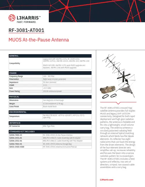
The RF-3081-AT001 crossed Yagi satellite antenna provides full-duplex MUOS and legacy UHF SATCOM connectivity. Designed for both rapid deployment and high-gain radiation patterns, the antenna is foldable and fits into a lightweight, small-volume carry bag. The antenna achieves a circularly polarized radiating field through an internal hybrid matching network which feeds two flat dipole elements. Its reflector has eight radial arms that cast back the energy from the driven elements. The design of the four-element director sets simplifies set-up, increases reliability and focuses the beam into a narrow radiation pattern for increased gain. The RF-3081-AT001 includes a feed system and reflector, two sets of directors, a tripod, two coaxial cable assemblies and a carry bag.RF-3081-AT001MUOS At-the-Pause AntennaGENERALCompatibilityLegacy SATCOM: AN/PRC-117G, RF-300M-V255, AN/PRC-117F(C), AN/VRC-103(V), AN/VRC-110, AN/PRC-158MUOS SATCOM: AN/PRC-117G (with MUOS upgrade and Diplexer), AN/PRC-158 (with MUOS upgrade)POWERFrequency Range240 - 380 MHz PolarizationRight hand circularly polarized Impedance50 ohm (nominal)VSWR1.5:1Gain+12.0 dBic Power Rating 200 W continuous powerPHYSICALDimensionsSee diagrams on back page Weight6.5 lbs maximum (2.95 kg)Color/Finish Black matte finishENVIRONMENTALTemperature Per MIL-STD-810F, -40°F to +159.8°F (-40°C to +71°C) operatingINTERFACERF Connector BNC-Type MaleSTANDARD KIT INCLUDES12006-7400-01RF-3081-AT001 At-the-Pause Antenna 12006-2511-A1BNC(M) to BNC(F) Cable Assembly with N Adapter 12006-2512-A1BNC(M) to BNC(F) Cable Assembly with TNC Adapter 12006-7403-01RF-3081-AT001 Antenna Storage Bag 10515-0500-4100RF-3081-AT001 Antenna Instruction ManualNon-Export Controlled InformationL3Harris Technologies is an agile global aerospace and defense technology innovator, delivering end-to-end solutions that meet customers’ mission-critical needs. The company provides advanced defense and commercial technologies across air, land, sea, space and cyber domains. RF-3081-AT001 MUOS At-the-Pause Antenna © 2020 L3Harris Technologies, Inc. | 04/2020 SP156 54.63 inches 24.25 inches28.25 inches TOP VIEWELEVATION VIEW1025 W. NASA Boulevard Melbourne, FL 32919。

八木天线端口宽度设计八木天线是一种特殊设计的天线,常用于无线通信和雷达系统中。
它能够在较小的空间内实现较高的增益和方向性,因此在各种通信领域得到广泛应用。
八木天线的端口宽度设计则是其关键的部分之一,端口宽度的合理设计可以使得天线在特定频段表现出较好的性能,因此对端口宽度的设计需认真考虑。
本文将重点介绍八木天线端口宽度设计的相关内容。
一、八木天线的基本结构八木天线由若干个平行排列的驻波器组成,通常由被反射器、驻波器和驱动器三部分组成。
其中被反射器用于反射驻波器发射的信号,驻波器则负责捕获和辐射电磁波,而驱动器用于输入或输出信号,是整个系统的输入输出端口。
八木天线的端口宽度设计主要涉及到驱动器的部分。
二、端口宽度设计的作用端口宽度是指驱动器的宽度,它会直接影响到天线的输入阻抗、频率特性和辐射模式。
合理的端口宽度设计可以使得天线在工作频段内具有较好的频率响应和阻抗匹配。
端口宽度还会影响到天线的辐射模式,进而影响到天线的覆盖范围和信号接收性能。
三、端口宽度设计的原则1. 频率响应匹配原则端口宽度应该能够使得天线在设计频段内具有较好的频率响应,即在设计频段内具有较高的增益和较小的波纹。
因此在端口宽度设计时,需要结合设计频段来调整端口宽度,以使得天线能够在频率响应上达到最佳性能。
2. 阻抗匹配原则合理的端口宽度设计应当能够使得天线的输入阻抗匹配到传输线或收发机的输出阻抗,以确保最大功率传输。
通过调整端口宽度可以对天线的输入阻抗进行调整,从而使得天线在设计频段内具有较好的阻抗匹配。
3. 辐射模式控制原则端口宽度的设计还会影响到天线的辐射模式,即天线的辐射方向和辐射角度。
合理的端口宽度设计可以使得天线在设计频段内具有所需的辐射模式,以满足特定的通信需求和工作环境。
四、端口宽度设计的方法1. 理论分析法根据八木天线的结构和天线阵列的特性,可以利用天线理论和电磁场理论进行端口宽度的设计。
通过计算和分析可以得到合理的端口宽度,以满足频率响应和阻抗匹配的要求。


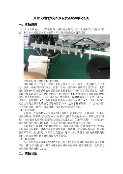
八木天线的方向图及阻抗匹配和极化匹配一、实验原理(1)八木天线是由一个有源振子(一般用折合振子)、两个无源振子:反射器(长的)和若干个无源引向器(短的)平行排列而成的端射式天线。
主瓣方向由有源振子指向引向器。
引向器略短于二分之一波长,主振子等于二分之一波长,反射器略长于二分之一波长,两振子间距四分之一波长。
此时,引向器对感应信号呈“容性”,电流超前电压90°;引向器感应的电磁波会向主振子辐射,辐射信号经过四分之一波长的路程使其滞后于从空中直接到达主振子的信号90,恰好抵消了前面引起的“超前”,两者相位相同,于是信号迭加,得到加强。
反射器略长于二分之一波长,呈感性,电流滞后90°,再加上辐射到主振子过程中又滞后90°,与从反射器方向直接加到主振子上的信号正好相差了180,起到了抵消作用。
一个方向加强,一个方向削弱,便有了强方向性。
发射状态作用过程亦然。
(2)阻抗匹配天线的一个重要特征,那就是“输入阻抗”。
在谐振状态,天线如同一只电阻接在馈线端。
常用馈线阻抗为50Ω,如果天线输入阻抗也是50Ω,那就达到了“匹配”,电台输出的信号就能全部从天线上发射出去;如果不“匹配”,一部分功率就会反射回电台的功放电路。
阻抗完全匹配才能达到最大功率传输。
不匹配时,发射机发射的电波将有一部分反射回来,在馈线中产生反射波,反射波到达发射机,最终产生为热量消耗掉。
接收时,也会因为不匹配,造成接收信号不好。
完全匹配,将不产生反射波,这样,在馈线里各点的电压振幅是恒定的。
阻抗完全匹配才能达到最大功率传输。
(3)极化匹配收、发信双方保持相同"姿势"为好。
振子水平时,发射的电波其电场与大地平行,称"水平极化波",振子与地垂直时发射的电波属"垂直极化波"。
收发双方应该保持相同的极化方式。
二、实验目的1、学习测量八木天线方向图方法2、测量八木天线在阻抗匹配条件下的反射系数3、研究在不同极化方式下的八木天线的功率变化。

一种用于集成天线封装(AiP)的低剖面、低成本的毫米波微带天线设计汪鑫;王启东;曹立强【摘要】讨论了毫米波微带天线的工作原理、结构及其与射频前端的集成.介绍了基于CST STUDIO SUITE 2014软件设计中心频率为27 GHz微带天线的整个设计流程.设计了以Rogers 5880有机基板为介质材料的27 GHz毫米波微带天线,相对于以LTCC为介质的天线拥有低成本、低剖面的优点.提出一种毫米波微带天线与射频前端的集成方案,建立了天线与帯通滤波器仿真模型并提取S参数.论证毫米波微带天线与射频前端集成的可行性.所设计的微带天线尺寸只有3.8 mm×3.5 mm,天线的增益达到了7.62 dBi,辐射效率高达93%,相对带宽为2.3%,且实测值与仿真值吻合得很好,验证了设计的正确性.%The working principle and structure of millimeter-wave microstrip antenna and its integration with RF front-end are discussed. The whole design process of the microstripantenna(whose center frequency is 27 GHz)based on CST STUDIO SUITE 2014 software is introduced. The millimeter-wave microstrip antenna working at 27 GHz was design,in which the Rogers 5880 organic substrate is utilized as the dielectric material. It has the advantages of low cost and low profile in comparison with the antenna taking LTCC as its dielectric. An integration scheme for millimeter-wave microstrip antenna and RF front-end is pre-sented. The simulation model of the antenna and band-pass filter(BPF)is established,and the S-parameter is extracted. The feasibility of the integration for millimeter-wave microstrip antenna and RF front-end is discussed. The size of the designed mi-crostrip antenna is only 3.8 mm×3.5mm,the gain of the antenna can reach up to 7.62 dBi,the radiation efficiency can reach up to 93%,and the relative bandwidth is 2.3%. The measured results are in good agreement with the simulation values,which can verify the validity of the design.【期刊名称】《现代电子技术》【年(卷),期】2017(040)019【总页数】5页(P1-5)【关键词】毫米波;微带天线;系统集成;辐射效率【作者】汪鑫;王启东;曹立强【作者单位】中国科学院微电子研究所,北京 100029;华进半导体封装先导技术研发中心有限公司,江苏无锡 214135;中国科学院微电子研究所,北京 100029;华进半导体封装先导技术研发中心有限公司,江苏无锡 214135;中国科学院微电子研究所,北京 100029;华进半导体封装先导技术研发中心有限公司,江苏无锡 214135【正文语种】中文【中图分类】TN82-34Abstract:The working principle and structure of millimeter⁃wave microstrip antenna and its integration with RF front⁃end are discussed.The whole design process of the microstrip antenna(whose center frequency is 27 GHz)based on CST STUDIO SUITE 2014 software is introduced.The millimeter⁃wave microstrip antenna working at 27 GHz was design,in which the Rogers 5880 organic substrate is utilized as the dielectricmaterial.It has the advantages of low cost and low profile in comparison with the antenna taking LTCC as its dielectric.An integration scheme for millimeter⁃wave microstrip antenna and RF front⁃end is pre⁃sented.The simulation model of the antenna and band⁃pass filter(BPF)is established,and theS⁃parameter is extracted.The feasibility of the integration for millimeter⁃wave microstrip antenna and RF front⁃end is discussed.The size of the designed mi⁃crostrip antenna is only 3.8 mm×3.5 mm,the gain of the antenna can reach up to 7.62 dBi,the radiation efficiency can reach up to 93%,and the relative bandwidth is 2.3%.The measured results are in good agreement with the simulation values,which can verify the validityof the design.Keywords:millimeter wave;microstrip antenna;system integration;radiation efficiency为了实现海量的数据传输和弥补匮乏的可用频谱,提高载波频率是必然的解决方案。