0.65m短背射天线说明书(SLBS06-8010)
- 格式:doc
- 大小:1.45 MB
- 文档页数:3

7820788Rev: CMountFeedShield omitted for clarityShieldRadome USX8 shown for illustrative purposes onlyAlways read the entire manual before commencing installationSequence of Antenna AssemblyHX and USX Antennas Antenna Shield7820788GRE 06Bulletin Rev Status Model Version Version Rev Status 2 of 12page Installation InstructionsC RE 02© June, 2018 CommScopeNotice: CommScope disclaims any liability or responsibility for the results of improper or unsafe installation, inspection, maintenance, or removal practices.Aviso: CommScope no acepta ninguna obligación ni responsabilidad como resultado de prácticas incorrectas o peligrosas de instalación, inspección, mantenimiento o retiro. Avis : CommScope décline toute responsabilité pour les conséquences de procédures d’installation, d’inspection, d’entretien ou de retrait incorrectes ou dangereuses. Hinweis: CommScope lehnt jede Haftung oder Verantwortung für Schäden ab, die aufgrund unsachgemäßer Installation, Überprüfung, Wartung oder Demontage auftreten.Atenção: A CommScope abdica do direito de toda responsabilidade pelos resultados de práticas inadequadas e sem segurança de instalação, inspeção,manutenção ou remoção. Avvertenza: CommScope declina eventuali responsabilità derivanti dell’esecuzione di procedure di installazione, ispezione, manutenzione e smontaggio improprie o poco mScope 1100 CommScope Place SE P.O. Box 339, Hickory, NC 28603-0339(828) 324-2200 (800) Customer Service 24 hours North America: +1-800-255-1479 (toll free)Any country: +1-779-435-6500email:**************************************Page 3 of 127820788CONTENTS & INTRODUCTION SECTION 1INSTALLATION INSTRUCTIONSPage 4 of 127820788SAFETY INSTRUCTIONS SECTION 2INSTALLATION INSTRUCTIONSPage 5 of 127820788SAFETY INSTRUCTIONS SECTION 2INSTALLATION INSTRUCTIONSTightening of hardwareIt is recommended that all hardware is tightened to the torques specified in table 3.The integrity of the completed assembly depends on all fasteners being properly tightened.Table 3: Fastener Torque SpecificationsINSTALLATION INSTRUCTIONSSECTION 3COMPONENTS AND TOOLS 7820788Page 6 of 12Tools Required M6M8M10Ring and Open spanner (A/F)10mm 13mm 17mm Torque Wrench 7.7Nm - 38NmSockets (A/F)10mm13mm17mmGeneral ToolboxFastener materialFastener sizeM6M8M10Stainless Steel N-m 7.71938lbf-ft 5.71428GalvanizedN-m --38lbf-ft--28INSTALLATION INSTRUCTIONSSECTION 3COMPONENTS AND TOOLS7820788Page 7 of 12ComponentsSupplied ComponentsINSTALLATION INSTRUCTIONS SECTION 3COMPONENTS AND TOOLS 7820788Page 8 of 12ItemDescription RemarksA1Shield Assembly (part number *-1)A2Shield Assembly (part number *-2)A3Shield Assembly (part number *-3)A4Shield Assembly (part number *-4)B Shield Ring C Joint PlateDShield Ring Hardware Kit D1M10 x 30 Hex Hd Screw - sst, pass D2M10 Nut - sst, pass D3M10 Flat Washer - sst, pass D4M10 Large Flat Washer - Alum D5M10 Lock Washer - sst, passD6M6 x 16 Flanged Hex Hd Screw - sst, pass D7M6 Flanged Nut - sst, passE Shield Hardware KitE1M6 x 16 Flanged Hex Hd Screw - sst, pass E2M6 Flanged Nut - sst, passFShield/Reflector Hardware Kit F1M8 x 25 Hex Hd Screw - sst, pass F2M8 Large Flat Washer - sst, pass F3M8 Lock Washer - sst, pass F4M8 Nut - sst, passCDEFINSTALLATION INSTRUCTIONS SECTION 3COMPONENTS AND TOOLS 7820788Page 9 of 12ComponentsINSTALLATION INSTRUCTIONSSECTION 4ASSEMBLY OF SHIELD7820788Page 10 of 12INSTALLATION INSTRUCTIONSSECTION 4ASSEMBLY OF SHIELD7820788Page 11 of 12M8-Starting at the middle of each segment tighten to a torque of 19Nm 5%5%5%。
S5000系列手持定向天线数据手册CN_01A产品综述定向天线常用于安全部门和无线电管理部门定位发射源和干扰源的查找,也可以应用于EMC测试、场强扫描、基站检测维护、变电站电力系统检测维护、汽车EMI检测、医疗设备辐射、伪基站检测设备等领域。
S5000系列手持定向天线,频率范围覆盖10MHz~8GHz,携带运输方便、操作简单快捷,适合外携测量。
天线套装包含三个不同频段的定向天线和一个内置宽带低噪声放大器的手柄;天线与手柄以盲插的方式配合,一体快速插拔转换,可实现垂直或水平极化方向信号的测试;单个天线也可以直接通过N型母头连接设备使用;手柄内置宽带低噪声放大器和可充电电池,设计有“直通”和“放大”两种工作模式以提高接收信号的动态范围;外接有N型公头稳相低损柔性射频线缆连接频谱仪使用。
型号与主要指标天线增益10dB(典型值)极化方向水平,垂直手柄射频线 1.5米/N型,公头包装尺寸470 x 400 x 240mm净重0.45kg(含手柄0.96kg)0.32kg(含手柄0.83kg)0.50kg(含手柄1.01kg)产品外观设计特色◆手柄带有放大或直通开关功能,适合测试时大信号与小信号环境的切换。
当按下放大开关时亮绿灯,信号经过LNA 放大处于有源放大工作状态,按下开关灭灯时信号直通处于无源工作状态。
◆手柄底部带有1/4 英寸接口方便上三脚架固定测试;充电接口为手柄内锂电池充电。
手柄上部为机械指北针。
◆天线支持快速插拔切换不同频段天线,利用塑料弹性和N 头接口进行卡位固定。
手柄和天线当插入深度到位后会听到“咔”声音证明已经插好,拔出方法反之。
快插拔时注意天线与手柄的对接平衡线对接,避免损坏N 头及使用寿命。
◆手柄充电时指示灯红灯处于充电状态,绿灯时处于饱和状态。
不使用时请关闭手柄放大开关处于灭灯无源状态。
◆射频线避免90°弯折。
◆实测增益图表典型方向图和应用图800MHz方向图3GHz方向图6GHz方向图频谱频率精确中频分析测量关于鼎阳鼎阳科技(SIGLENT)是通用电子测试测量仪器领域的行业领军企业。


M O Q V T X R N P W U YS Parabolic Dish Antenna Feed Feed Bracket Back PlateAlignment Bracket Pole Bracket Pole Clamp Case Holder RF CableSelf-Bonding Tape Slice M10x130 BoltAdjusting Mechanism M6x20 Bolt M4x12 Bolt M4 Wing NutM4 Serrated Washer M6 Nut M6 WasherM6 Fender Washer M6 Spring Lock Washer M10 Square Washer M10 Jam NutM10 Fender Washer M10 Spring Lock Washer M10 NutA B C D E F G H I J K L M N O P Q R S T U V W X Y11111121224216425201281644444ITEMDESCRIPTIONQTYMikroTik Antenna assembly preview frontMikroTik Antenna D-5G-30D3-PAQuick setup guide and warranty information Package contents0. Items Required• 10mm Wrench • 17mm Wrench • PH2 Screw Driver •• This guide is written to be used with a MikroTik RB900 series outdoor device (sold separately) •1. Install Back Plate to Parabolic DishInstall Back Plate [D] to Parabolic Dish [A] using:[M] M6x20 Bolt x 8 pcs;[R] M6 Washer x 8 pcs;[T] M6 Spring Lock Washer x 8 pcs;[Q] M6 Nut x 8 pcs.Important:• Back Plate [D] must be aligned respectively to a bore in theParabolic Dish [A] - see Fig. 1;• M6 Nut [Q] tightening torque must be approximately 5 Nm.2. Install Antenna FeedInstall Antenna Feed [B] to Parabolic Dish [A] using:[C] Feed Bracket x 1 pc;[N] M4x12 Bolt x 4 pcs;[P] M4 Serrated Washer x 4 pcs.Install grounding fasteners:[O] M6 Wing Nut x 1 pc;[P] M4 Serrated Washer x 1 pc.Important:• Antenna Feed [B] and Feed Bracket [C] must be aligned respectively to the hole in the Parabolic Dish [A] - see Fig. 2;• M4x12 Bolt [N] tightening torque must be approximately 2 Nm.3. Assemble Alignment and Pole BracketsAssemble Alignment [E] to Pole Bracket [F] using:[M] M6x20 Bolt x 4 pcs;[S] M6 Fender Washer x 4 pcs;[T] M6 Spring Lock Washer x 4 pcs;[Q] M6 Nut x 4 pcs.Install Adjusting Mechanism [L] using:[R] M6 Washer x 2 pcs;[Q] M6 Nut x 2 pcs.Important:• Mount Alignment Mechanism's [L] bolt with larger shank diameterthrough the corresponding hole in the Pole Bracket [F] - see Fig. 3;• Secure Alignment Mechanism [L] by tightening M6 Nuts [Q] toapproximately 5 Nm;• Do not tighten other fasteners rmly until step 10.4. Assemble Brackets to Back PlateAssemble Alignment [E] and Pole Bracket [F] to Back Plate [D] using: [M] M6x20 Bolt x 4 pcs;[S] M6 Fender Washer x 4 pcs;[T] M6 Spring Lock Washer x 4 pcs;[Q] M6 Nut x 4 pcs.Install Adjusting Mechanism [L] using:[R] M6 Washer x 2 pcs;[Q] M6 Nut x 2 pcs.Important:• Mount Alignment Mechanism's [L] bolt with larger shank diameter through the corresponding hole in the Alignment Bracket [E] - see Fig. 4;• Secure Alignment Mechanism [L] by tightening M6 Nuts [Q] toapproximately 5 Nm;• Do not tighten other fasteners rmly until step 9.5. Attach MikroTik Radio to Back PlateAttach a MikroTik RB900 series outdoor device to Case Holder [H] using: [-] M3x8 Bolt x 4 pcs (Comes with MikroTik Radio) - see Fig. 5.1. Attach Case Holder [H] to Back Plate [D] by tting Case Holder’s hinges into the Back Plate’s ange - see Fig. 5.2. Secure Case Holder using: [O] M4 Wing Nut x 1 pc.Important:• M3x8 Bolt [-] tightening torque must be approximately 1.5 Nm.6. Install RF CablesRemove the cover from MikroTik Radio and install the RF Cables [I]. Connect vertical polarization (arrow V) to CH0, horizontal polarization (arrow H) to CH1 - see Fig. 6.Insulate the RF Cable [I] ends which are connected to Antenna Feed [B]by using: [J] Self-Bonding Tape Slice x 2pcs.• Remove the plastic liner from both sides;• Stretch the tape to 2/3 of its width;• Apply half-lapped layers clockwise.The RF Cable [I] ends which are connected to MikroTik Radio are insulated by the cover.Fit back the MikroTik Radio cover.Important:• RF Cables [I] connector tightening torque must be approximately 0.5 Nm.7. Install Pole FastenersDetermine the pole diameter which MikroTik Antenna will be attached to. • If the pole diameter is less than 60mm( 2.375”) use the hole pattern from Fig. 7.1 to install the M10x130 Bolts [K];• If the pole diameter is 60 - 100mm (max) use the hole pattern from Fig. 7.2.Install M10x130 Bolt [K] x 4 pcs using:[U] M10 Square Washer x 4 pcs;[V] M10 Jam Nut x 4 pcs.Important:• M10 Jam Nut [V] tightening torque must be approximately 4 Nm.8. Attach Antenna to PoleMikroTik Antenna is design to t the pole diameter up to 100mm( 3.9”).Attach MikroTik Antenna to pole as shown in Fig. 8 using:[G] Pole Clamp x 2 pcs;[W] M10 Fender Washer x 4 pcs;[X] M10 Spring Lock Washer x 4 pcs;[Y] M10 Nut x 4 pcs.Important:• M10 Nuts [Y] tightening torque must be approximately 25 Nm.M3x8H OFIG. 5.1FIG. 5.2DHVJIFIG. 6 BIF POLE Ø < 60mmIF POLE Ø > 60mmV U KFIG. 7.3FIG. 7.2FIG. 7.1ØMAX = 100mmGWXYFIG. 8Turn Alignment Mechanism [L] to precisely adjust the azimuth - see Fig. 9.After setting the azimuth, tighten rmly the corresponding fasteners - see Fig. 4.Important:• M6 Nuts [Q] tightening torque must be approximately 7 Nm.10. Adjust ElevationTurn Alignment Mechanism [L] to precisely adjust the elevation - see Fig. 10.Important:• M6 Nuts [Q] tightening torque must be approximately 7 Nm.Copyright and Warranty informationCopyright MikroTikls SIA. This document contains information protected by copyright law. No part of it may be reproduced or transmitted in any form without prior written permission from the copyright holder. RouterBOARD, RouterOS, RouterBOOT and MikroTik are trademarks of MikroTikls SIA. All trademarks and registered trademarks appearing in this document are the property of their respective holders.Hardware. MikroTik warrants all RouterBOARD series equipment for the term of twelve (12) months from the shipping date to be free of defects in materials and workmanship under normal use and service, except in case of damage caused by mechanical, electrical or other accidental or intended damages caused by improper use or due to wind, rain, re or other acts of nature.To return failed units to MikroTik, you must perform the following RMA (Return Merchandise Authorization) procedure. Follow the instructions below to save time, e orts, avoid costs, and improve the speed of the RMA process.1. If you have purchased your product from a MikroTik Reseller, please contact the Reseller company regarding all warranty and repair issues, the followinginstructions apply ONLY if you purchased your equipment directly from MikroTik in Latvia.2. MikroTik does not o er repairs for products that are not covered by warranty. Exceptions can be made for: CCR1016-12G, CCR1016-12G-BU,CCR1036-12G-4S, RB1100, RB1100AH, RB1100AHx2, RB1200, RB600, RB600A and RB800 as a paid service (fees apply).3. Out-of-warranty devices and devices not covered by warranty sent to Mikrotik will be returned to the sender at sender's cost. If the customer has notorganized return of such rejected devices within 12 months from the day of arrival, MikroTik has the right to discard them.RMA Instructions are located on our webpage here: This document is provided “as is” without a warranty of any kind, expressed or implied, including, but not limited to, the implied warranty of merchantability andtness for a particular purpose. The manufacturer has made every e ort to ensure the accuracy of the contents of this document, however, it is possible that it may contain technical inaccuracies, typographical or other errors. No liability is assumed for any inaccuracy found in this publication, nor for direct or indirect, incidental, consequential or other damages that may result from such an inaccuracy, including, but not limited to, loss of data or pro ts. Please report any inaccuracies found**********************。
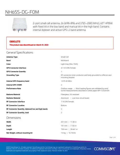
2-port small cell antenna, 2x (698-896 and 1710–2180 MHz), 65° HPBWwith fixed tilt in the low band and manual tilt in the high band. Containsinternal diplexer and active GPS L1 band antenna.OBSOLETEThis product was discontinued on: March 31, 2023General SpecificationsAntenna Type Small CellBand MultibandColor Light Gray (RAL 7035)GPS Connector Interface 4.1-9.5 DIN FemaleGPS Connector Quantity1Grounding Type RF connector inner conductor and body grounded to reflector andmounting bracketInternal GPS frequency band1,575.42 MHzInternal GPS VSWR2Performance Note Outdoor usage | Wind loading figures are validated by windtunnel measurements described in white paper WP-112534-EN Radome Material Fiberglass, UV resistantRadiator Material Aluminum | Low loss circuit boardRF Connector Interface7-16 DIN FemaleRF Connector Location BottomRF Connector Quantity, diplexed low and high bands2RF Connector Quantity, total2DimensionsWidth301 mm | 11.85 inDepth181 mm | 7.126 inLength728 mm | 28.661 inNet Weight, without mounting kit7.6 kg | 16.755 lb15Page ofElectrical SpecificationsImpedance50 ohmOperating Frequency Band1710 – 2180 MHz | 698 – 896 MHzPolarization±45°Electrical SpecificationsFrequency Band, MHz698–806806–8961710–18801850–19901920–2180 Gain, dBi10.110.51414.114 Beamwidth, Horizontal,degrees6965606061Beamwidth, Vertical, degrees39.935.714.113.513.1 Beam Tilt, degrees000–160–160–16 USLS (First Lobe), dB1515121313Front-to-Back Ratio at 180°,dB2432242525Isolation, Cross Polarization,dB2525252525VSWR | Return loss, dB 1.5 | 14.0 1.5 | 14.0 1.5 | 14.0 1.5 | 14.0 1.5 | 14.0 PIM, 3rd Order, 2 x 20 W, dBc-153-153-153-153-153Input Power per Port,maximum, watts125125125125125 Electrical Specifications, BASTAFrequency Band, MHz698–806806–8961710–18801850–19901920–2180 Gain by all Beam Tilts,average, dBi9.510.113.513.813.6Gain by all Beam TiltsTolerance, dB±1.3±0.8±0.7±0.5±0.6Gain by Beam Tilt, average, dBi 0 ° | 14.08 ° | 13.516 ° | 12.90 ° | 14.28 ° | 13.816 ° | 13.30 ° | 14.08 ° | 13.616 ° | 13.3Beamwidth, HorizontalTolerance, degrees±7.5±4.6±5.1±5.4±7.7Beamwidth, VerticalTolerance, degrees±6±3.2±1.1±0.7±0.8USLS, beampeak to 20° abovebeampeak, dB121313Front-to-Back Total Power at180° ± 30°, dB19202120191617181616Page of25CPR at Boresight, dB1617181616 CPR at Sector, dB959910 Mechanical SpecificationsWind Loading @ Velocity, frontal98.0 N @ 150 km/h (22.0 lbf @ 150 km/h)Wind Loading @ Velocity, lateral77.0 N @ 150 km/h (17.3 lbf @ 150 km/h)Wind Loading @ Velocity, maximum188.0 N @ 150 km/h (42.3 lbf @ 150 km/h) Wind Loading @ Velocity, rear99.0 N @ 150 km/h (22.3 lbf @ 150 km/h)Wind Speed, maximum241 km/h (150 mph)Packaging and WeightsWidth, packed409 mm | 16.102 inDepth, packed299 mm | 11.772 inLength, packed976 mm | 38.425 inWeight, gross13.9 kg | 30.644 lbRegulatory Compliance/CertificationsAgency ClassificationISO 9001:2015Designed, manufactured and/or distributed under this quality management systemREACH-SVHCCompliant as per SVHC revision on /ProductComplianceIncluded ProductsBSAMNT-3–Wide Profile Antenna Downtilt Mounting Kit for 2.4 - 4.5 in (60 - 115 mm) OD round members.Kit contains one scissor top bracket set and one bottom bracket set.* FootnotesPerformance Note Severe environmental conditions may degrade optimum performancePage of35Wide Profile Antenna Downtilt Mounting Kit for 2.4 - 4.5 in (60 - 115 mm)OD round members. Kit contains one scissor top bracket set and onebottom bracket set.Product ClassificationProduct Type Downtilt mounting kitGeneral SpecificationsApplication OutdoorColor SilverDimensionsCompatible Diameter, maximum115 mm | 4.528 inCompatible Diameter, minimum60 mm | 2.362 inWeight, net 6.2 kg | 13.669 lbMaterial SpecificationsMaterial Type Galvanized steelPackaging and WeightsIncluded Brackets | HardwarePackaging quantity1Weight, gross 6.4 kg | 14.11 lbRegulatory Compliance/CertificationsAgency ClassificationCE Compliant with the relevant CE product directivesCHINA-ROHS Below maximum concentration valueISO 9001:2015Designed, manufactured and/or distributed under this quality management systemREACH-SVHC Compliant as per SVHC revision on /ProductComplianceROHS CompliantUK-ROHS Compliant45Page ofPage of 55。
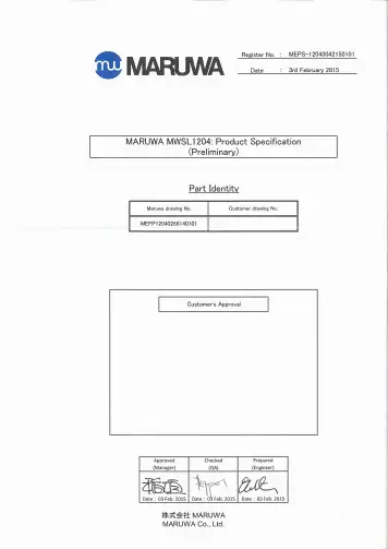
1.ScopeThis specification applies to the MARUWA MWSL1204 GPS L1 active antenna, which in addition to the basic MWSL1204 form can be supplied in two optional forms: MWSL1204R supplied with a loosely fitting black radome cap/cover for external use and MWSL1204SB supplied with a loosely fitting plastic sleeve for internal use.2.SpecificationsMinimum Typical Maximum UnitPart Number MWSL1204 (MARUWA dwg No: MEFP12040268140101)Type Dielectric-loaded Quadrifilar HelixConnector Type Refer to embedding information / connection diagramsFrequency 1573.421575.421577.42MHzPolarisation Right-hand Circular PolarisedVoltage (+ve to co-ax centre-wire). 1.83 3.6VCurrent 3.1 3.4 3.9mAGain (no ground-plane)+15+16dBic at zenithBeamwidth >115DegreesBandwidth (3dB)15MHzAxial Ratio <2.0at zenithVSWR <2.0:1 2.3:1Impedance 50OhmsNoise Figure 0.80.9dBInput 3rd Order Intercept Point -7dBmOperating Temperature -40+20+85°C Overall Dimensions Refer to mechanical drawings mmWeight (excl radome or sleeve)7.0grams3.DimensionsBasic MWSL1204 form:Rev.Date Description Approved Checked PreparedO.Leisten K.Inagaki F.Frimpong 0103 Feb. 2015Issue of the first edition Product Specification (Preliminary)MARUWA Antenna ProductsDocument №MEPS-12040042150101MWSL1204Notes:1.MARUWA Europe assembly drawingMEFP12040268140101 applies.2. Units in mm.3. For connection layout and pad-size, through-hole and connector details please refer to padlayout and designation definitions.MWSL1204R form with loosely fitting black radome cap.MWSL1204SB form with loosely fitting translucent sleeve.Rev.Date Description Approved Checked PreparedK.Inagaki F.Frimpong O.Leisten 0103 Feb. 2015Issue of the first edition Notes:1.MARUWA Europe assembly drawingMEFP1204R268140101 applies.2. Units in mm.3. Black cap/radome unit: METC120X0158140101shown fitted but actually shipped separately.4. For connection layout and pad-size, through-hole and connector details please refer to padlayout and designation definitions.Notes:1.MARUWA Europe assembly drawingMEFP1204S278140101 applies.2. Units in mm.3. Translucent sleeveunit: METC120X0198140101shown fitted but actually shipped separately.4. For connection layout and pad-size, through-hole and connector details please refer to padlayout and designation definitions.4.Product DescriptionTypical Gain PatternThe MWSL1204 GPS L1 miniature high-gain active dielectric-loaded antenna uses MARUWA’sdistinctive materials technology to provide unrivalled circularly-polarised gain from a uniquely small volume. It enables excellent GPS performance in tightly integrated devices that require good positional accuracy.By combining a high-quality dielectric antenna with a high-performance low-noise amplifier the MWSL1204 active antenna provides an excellent solution wanting an active gain input.The MWSL1204 antenna has a sharp filtering response and is particularly suitable for applications where:*The device is hand-held, body-worn, or otherwise surrounded by materials of high relative dielectric-constant which would de-tune other antennas.* The antenna is installed in close proximity to other antennas sharing the same device housing and ground-plane: for example Bluetooth®, WiFi, LTE,WiMax and other cellular radio antennas.* The antenna must fit into a very small installation volume with close proximity to other components and little or no space available for a ground-plane.* The GPS receiver requires 20dB or more of input pre-amplification.* The device is noisy and requires low-noise front-end amplification to achieve the required GPS sensitivity.* Excellent performance with extremely low power consumption.* The orientation of the device is random.* The antenna must be embedded into the device.The MWSL1204 antenna is balanced, which isolates it from the device ground enabling it to reject common-mode noise present on the device ground-plane. The construction and materials of the antenna constrain its near-field region to occupy a very small volume so that materials near theantenna cause negligible de-tuning effects. Therefore the antenna maintains its pattern and efficiency in the presence of dielectric loading. The MARUWA MWSL1204 dielectric-loaded antenna also has a useful filtering fuction as the antenna strongly attenuates signals from the cellular and ISM frequency bands.-96-90-84-10-5051015200611172328343945515662687379849096101107113118124129135141146152158163169174180186191197203208214219225231236242248253287293298304309315321326332338343349354Azimuth Gain (G φ) for Elevation (θ)Low Noise Amplifier Characteristics.Wide-band Frequency ResponseAntenna Integration Options Pad Number Function 1Ground 2RF Out, DC In 3GroundDimensions mm 0.1A 5.0B 2.1C 5.75D 2.8E 4.0F 6.2G3.3H9.5J3.1K 3.0Pad Layout and Pad DesignationsRev.Date Description Approved Checked PreparedK.Inagaki F.Frimpong O.Leisten 0103 Feb. 2015Issue of the first edition MWSL1204 antennas may be mounted externally (order MWSL1204R version) orembedded within a device (order MWSL1204SB version). The product is designed to tuneto the correct frequency when the sleeve or radome-cap is fitted. In thecase of externalmounting the device housing should be designed to seal around the radome-cap groove inorder to provide mechanical support. When internally mounted the sleeve should befitted and the antenna can be fitted into a corner cut-out in the device PCB. Adjacentmetal ground-surfaces (PCB ground-layers or screening cans) can uplift the radiationefficiency compared with the antenna operating separately in free-space. For optimumperformance the gap between the antenna and the copper edge of the PCB ground-planeshould be greater than 5mm. MARUWA can provide application notes with integrationguidance. Please contact your MARUWA sales representative for this information.123AC C B DE D EF HJ KGOrdering Guide for the MWSL1204 AntennaMaruwa can supply three options. Please order according the the following table:Please note that when MWSL1204R or MWSL1204SB are ordered the radome or sleeve parts shall be deliveredin separate packaging and will not be fitted to the MWSL1204 product. The radome and sleeve parts are designed to fit loosely.5.Notes1. The contents of this document assure the characteristics and quality of the antenna components themselves.2. Please ensure that they work correctly in the installed configuration and method of use of your equipment.。
SCE-450C型4.5米天线安装、使用、维护手册精彩文档西安航天恒星科技股份有限公司手册使用说明 :SCE-450C型天线是实现C波段与Ku波段共用的卫星地球站天线。
使用时,只需根据不同的使用情况换上C波段馈源或Ku波段馈源即可。
《SCE-450C型4.5米天线安装、使用、维护手册》针对C波段与Ku波段的使用,除了馈源安装方式(附图13A为C波段馈源,13B 为Ku波段馈源)和天线电气特性指标不同外,其余内容全部通用。
精彩文档安全方面的注意事项安全声明:以下声明适用于本手册的全过程。
在天线安装前必须仔细阅读本手册,并切实按照规定的步骤及方法进行操作,以保障人身及设备的安全。
1. 必须严格按照要求制作地基,只有在地基达到预定的强度后,方可对天线进行安装。
2. 在吊装过程中,应注意人员及设备的安全;保证设备在吊装中平稳。
3. 在无吊车情况下安装,应特别小心,以确保人身及设备的安全。
4. 在首次运行前,应对所有有润滑要求的部件进行润滑。
其中,减速器用指定的润滑油润滑;方位轴、俯仰轴用稀油注入油杯润滑;丝杠螺母用润滑脂润滑。
5. 在调整限位器工作时,应特别注意不要使丝杠脱出减速器,尤其是俯仰丝杠脱出减速器将造成天线严重损坏。
在方位、俯仰二丝杠的左,右(或上,下)极限位置限位器安装完毕后,首先进行试运行,确保限位器工作无误。
6. 天线具有软件和硬件两重限位保护。
为确保天线使用安全,在转动天线时,应使用ACU,并将软件限位设置在硬件限位之前。
7. 手轮用后应取下,并装上蜗杆轴盖,切勿将手轮套在蜗杆轴上,以免电动时,发生意外事故。
8. 应注意检查波纹喇叭封口材料是否破损或漏水,尤其是在冰雹或大雨之后,若波纹喇叭口漏水,将影响系统正常工作,严重时造成HPA或SSPA损坏。
若封口材料破损,应及时更换。
精彩文档1. 4.5米天线简介SCE-450C型4.5米卫星通信天线是西安航天恒星科技实业(集团)公司研制生产的卫星通信地球站天线。

高效率宽频带新型短背射螺旋天线
刘波;高选正
【期刊名称】《空间电子技术》
【年(卷),期】1994(000)004
【摘要】给出一种适合空间应用的新型高效率宽带背射螺旋天线,应用背景是UHF频段卫星移动通信。
在L波段给出了1:5缩比样机的方向图、阻义气风发及增益等参数的实测结果。
实验结果表明,此项新方案结合了谐振腔型天线效率高以及螺旋天线频带宽的长处,其口面频率达到甚至略大于1,而输入阻抗带宽(驻波比<1.2)接近15%,方向性增益带宽(下降1dB)可达12%,较之一般短背射天线1-2%的带宽有很在改进。
【总页数】8页(P8-15)
【作者】刘波;高选正
【作者单位】西安空间无线电技术研究所;西安空间无线电技术研究所
【正文语种】中文
【中图分类】TN823.31
【相关文献】
1.反射面背射螺旋天线设计 [J], 孙大媛
2.S波段短背射式地面遥测站天线 [J], 颜红兵
3.单线背射螺旋作馈源的短背射天线 [J], 郝晋;李祥林
4.背射模螺旋天线及其应用研究 [J], 李渠塘;胡关平
5.S波段短背射式地面遥测站天线 [J], 颜红兵
因版权原因,仅展示原文概要,查看原文内容请购买。
Installing the Hughes BGAN Remote AntennaProduct description – BGAN Remote AntennaThe Hughes BGAN Remote Antenna (HNS Part No. 9501286-0001) is designed to be permanently installed with the Basic Fixed Mount Kit (HNS part number 3004066-0002).Important Notes:•The Hughes BGAN Remote Antenna and its cable assembly are designed for a one-time permanent installation. If the Remote Antenna is decommissioned, then the RF cable must be replaced with a newcable before the antenna is reinstalled at the same or a different location.•The cable assembly supplied (10.0m), forms an integral part of the antenna system and is made to a specific length in order to meet the system specifications. The cable must not be cut to a shorter length,nor must cables be added to the cable run.•It is essential that only the supplied cable is used. Third party cables may not be used; their use will invalidate the warranty of the antenna and may cause system malfunction.The BGAN Remote Antenna kit primarily consists of the antenna and cable for connection to the BGAN satellite modem terminal. All necessary fixings are included.Installation InstructionsStep 1: Inspecting the partsMake sure you have all parts listed on the shipment box before beginning the installation; you should have the following parts:1. Flat panel antenna2. 10m coaxial cable terminating in N(M) and SMA(M) connectors3. Strain relief adapter4. Cable retaining clips5. ¼” UNC nuts6. Self-amalgamating tape7. Zip strapStep 2: Determining where to install the terminalIn order for your terminal to work correctly, it must be installed in a location that provides a clear, unobstructed, line of sight between the terminal and the satellite. Any objects such as building structures or trees may degrade the quality of the satellite to terminal connection. To determine where to install the BGAN remote antenna, you need to determine that you have both a clear unobstructed line of sight to the satellite and that your fixed mount is aimed in the approximate direction to the satellite.To determine the direction from your location to the satellite follow the steps below:1. Unpack the Hughes 9201 BGAN Satellite Modem and connect it to a Personal Computer or Mac thathas the LaunchPad MMI Software installed. Follow the instructions in the Hughes 9201 user guide.2. Power up the Hughes 9201 and launch the LaunchPad Software.3. After LaunchPad connected successfully to the Hughes 9201 it shows the coverage map of the BGANsystem. Click on the map to identify your approximate position. Figure 1 shows an example.4. LaunchPad now indicates elevation angle and compass direction of the available BGAN satellite(s) foryour location.5. Use the antenna pointing mode of the Hughes 9201 to verify that you can obtain the BGAN satellitesignal from the location where the Remote Antenna is to be installed.Figure 1 - LaunchPad Setup screen showing the recommended antenna pointing angleStep 3: Mounting the pole base bracketYou may install the fixed mount on any structurally sound surface; either on a horizontal, or vertical, or a sloped surface such as a roof or wall.The pole is shipped attached to the base bracket. Mount the base bracket of this assembly to the structure with the appropriate hardware (not included). Once the base bracket is mounted, perform the following steps:1. Insert the bubble level (figure 3) into the end of the pole (pipe) opposite the base bracket. The bubblelevel fits inside the pole.2. Loosen the pole attachment fasteners at the base bracket so the pole can swivel (figure 2).3. Swivel the pole until the end of the pole where BGAN Remote Antenna will be installed is vertical (asshown in Figure 4). Adjust the pipe position until the bubble is centered inside the circles on the topsurface of the bubble level as shown in figure 3.4. Tighten the pole attachment fasteners on the base bracket (figure 2).Step 4: Mounting the terminal bracketMount the terminal bracket to the back of the antenna using the fasteners and spanner provided (figure 5).Figure 2 - Base bracket Figure 3 - Bubble levelFigure 4 – Pole assembly Figure 5 – Terminal BracketStep 5: Mounting the terminal bracket onto the pole1. Slide the pole collar of the terminal bracket over the end of the pole (figure 6).2.Leave the pole collar bolts loose to allow for azimuth adjustment during pointing.Step 6: Attaching Antenna feed cable to AntennaImportant Notes:• The cable assembly supplied (10.0m), forms an integral part of the antenna system and is made to a specific length in order to meet the system specifications. The cable must not be cut to a shorter length, nor must cables be added to the cable run.• It is essential that only the supplied cable is used. Third party cables may not be used; their use will invalidate the warranty of the antenna and may cause system malfunction.•It is important not to stress the connection to the antenna during installation of the coaxial antenna cable. • The minimum bend radius of the cable is 2” (50mm) however it is recommended that 4” (100mm) is not exceeded.1. Attach the cable to the mounting pole via a zip strap to take the weight of the cable.2. Mate the connector to the antenna firmly by hand but do not over tighten.3. Weatherproof the connection using the self-amalgamating tape provided (figure 7).4.Route the cable to the BGAN satellite modem terminal avoiding any sharp bends, extremes in temperature, and compression of the cable.Figure 6 – Pole collar Figure 7 – Weatherproofed ConnectorStep 7: Attaching Antenna Feed cable to the Hughes 9201 BGAN Satellite ModemImportant Note:• The GPS fix needs to be obtained prior to connecting to the antenna.•The Hughes 9201 should be placed in a location with good visibility of the GPS satellite constellation toobtain a GPS fix.1. Open the rubber plug on the rear of the modem terminal and unplug the MCX connector inside (refer tofigures 8a and 8b).The MCX connector is prone to damage. Ensure that the utmost care is taken when mating and un-mating the connectors. This connection must not be made more than 100 times.Figure 8a – Opening the rubber plug Figure 8b – Disconnecting the MCX connector2. Carefully insert the strain relief adapter into the MCX connector of the terminal. Make sure the adapter iswell aligned with the terminal connector. Rotate the adapter such that the knob on the adapter points to the knob on the housing as shown in figure 8c and the internal RF cable fits into the slot in the adapter. Gently push the adapter down until it is flush with the terminal housing as shown in figure 8d. Don’t apply excessive pressure – try to realign the connector if the adapter does not slide in easily.Figure 8c – Alignment of strain relief adapter Figure 8d – Insert strain relief adapter flush with terminal housing3. Attach the antenna feed cable to the rear of the modem terminal using the provided cable clamps in theposition detailed in figure 9a. Note there are two different size cable clamps to fit the varying thickness in cable.4. Carefully plug the SMA connector into the strain relief adapter as shown in figure 9b. Tighten theconnection by hand. Excessive force applied using a tool, could turn the adapter and damage the internal antenna cable.Figure 9b – Insert SMA plug into adapter Figure 9a – Attach antenna feed cableStep 8: Connecting the Hughes 9201 BGAN TerminalRefer to the Hughes 9201 Terminal User Guide for instructions to connect a Personal Computer or Mac to the terminal.Step 9: Pointing the BGAN Remote Antenna.For optimum performance, the remote antenna must be accurately pointed at the satellite. The instructions in this section explain how to mechanically adjust the antennas’ elevation and azimuth angles. These adjustments are required for pointing.Important Notes:• To aid pointing the antenna, refer to the Hughes 9201 Terminal User Guide on how to put the terminal inantenna pointing mode.• The terminal must be powered ON for pointing.•The GPS fix needs to be obtained prior to connecting to the antenna as explained in step 7.• The BGAN Terminal needs to be left registered on the network otherwise a new GPS fix may be required. • The Hughes 9201 may need to acquire a new GPS fix if it has been switched off for more than 42 days. Inthis case it must be disconnected from the external antenna and placed in a location with good visibility of the GPS satellite constellation to obtain a GPS fix. Note: Hughes 9201 s oftware version 3.8.0.3 and newer incorporates a Loss of Acquisition (LOA) timer that allows the 42 day time limit to be extended indefinitely as long as you register with the network at least once within the rolling 42 day period.To adjust elevation, refer to Figure 10:1. Loosen the two bolts in the curved slots on the terminal bracket.2. Read the elevation angle from the elevation scale on the terminal bracket, using the red edge on thepole collar as the angle indicator. View this edge through the curved slot on the terminal bracket. 3. Pivot the antenna to obtain the desired elevation.To adjust azimuth, refer to Figure 11:4. Loosen the two bolts on the pole collar.5. Move the terminal to either side, in small increments, as necessary.When you have maximized the signal quality, as instructed in the User Guide:6. Tighten the two bolts in the curved slots on the terminal bracket to lock down the elevation adjustment.7. Be careful not to change the terminal’s orientation while tightening the bolts.8. Tighten the two bolts on the pole collar to lock down the azimuth adjustment.9. Make sure all other fasteners on both brackets are tight.Figure 10 – Adjusting elevation Figure 11 – Adjusting azimuthLightning Protection and SafetyA lightning strike on the antenna, mounting hardware or cable may cause death or serious injury and is likely to damage both the antenna and the BGAN Terminal.It is therefore essential that the installer does not employ an installation location, which is likely to experience a lightning strike, and make suitable grounding and lightning protection arrangements to minimize any possibility of injury or damage. Professional local advice should be sought with respect to these matters. Hughes accepts no liability for any injury or damage caused by lightning strikes.DisclaimerWhilst prepared in good faith, Hughes makes no warranty or representation as to the accuracy, completeness or fitness for purpose of this document or its contents and all warranties, whether express or implied are excluded. Hughes, to the maximum extent permitted by law, excludes any liability arising from the use of this document or its contents. Users’ attention is brought to the fact that the local applicable laws and regulations as to the use of the remote antenna may apply and it is the user’s responsibility to identify and comply with these.。

虹科● 广播与卫星通信●宽带HFC和FTTx网络用于信号分配的综合射频解决方案Integrated RF Solutions for Signal Distribution缩写列表List of abbreviationsAC APC ASI CATV CCAP CMTS CWDM DC DOCSIS DWDM EDFA HFC IRD LNB MAC MGC OMI RF RGC RU Rx SMA SNMP TRAC Tx 交流电自动输出功率控制异步串行接口有线电视系统发射端有线电视融合接入技术平台电缆调制解调器终端系统粗波分复用直流电有线电缆数据服务接口规范密集波分复用掺铒光纤放大器混合光纤-同轴电缆综合解码卫星接收机低噪声降频放大器(高频头)媒体接入控制手动增益控制光调制指数射频冗余路径增益补偿机架单元接收端连接头类型:超小型A版简单网络管理协议捕捉接收机动作控制装置虹科226光载射频传输RFoF 冗余开关双向开关分配与组合矩阵分路器,合路器与放大器射频信号传输附件DOCSIS 3.1 模块化HFC头端分布式CCAP解决方案DOCSIS 3.1 光节点和放大器DEV 网页界面虹科服务 273首选合作伙伴分配放大器、分路器和合路器 ᅠ冗余开关系统与分配与组合矩阵路由产品和多路复用器RFoF产品用于电缆和HFC网络的DOCSIS 3.1设备20多年来,DEV Systemtechnik为全球主要的电信运营商和网络运营商开发和制造了整个RF信号分配链的集成系统。
凭借其在模拟技术和工程方面的成熟记录,DEV Systemtechnik为卫星、广播和军事用途的光纤和同轴电缆以及HFC(混合光纤同轴电缆)馈电提供了完美的信号传输。
成立于1995年,DEV已经成为可靠信号传输和分配的首选合作伙伴。
质量管理认证DEV的信号传输设备和系统的开发、生产和销售的质量管理通过了ISO 9001:2015认证。
DEV的独特之处DEV努力用最小的空间以最佳的成本提供出色的性能解决方案。
¬ 886-2-8698-3699ß Product name Description VersionLS20126 Stand-alone GPS with magnetic sensor smart antennamodule, 9600BPS0.4Datasheet of stand-alone GPS with magnetic sensor smartantenna module, LS201261IntroductionThe LOCOSYS LS20126 GPS smart antenna module is a high sensitivity, low power, SMD type, 20 channels with built-in magnetic sensor, 3-axial acceleration sensor L1 GPS receiver and 10mm patch antenna designed for portable applications. The LS20126 is designed for easy and quick integration into customer applications, especially for slow speed or pedestrian mode. This module is pin to pin compatible to LOCOSYS LS200x6 series GPS module.2Featuresz GPS + magnetic sensor + 3-axial acceleration sensorz Easy to install (SMT process capable)z SiRF Star III high sensitivity solutionz Support 20-channel GPSz Fast TTFF at low signal levelz Capable of SBAS (WAAS, ENGOS, MSAS)z Pin-to-pin compatible with LS20026 (SiRF solution), LS20036 (MediaTek solution), LS20056 (Atheros solution) and LS20076 (ublox solution)z Provides compass heading over a wide of conditionsz0.5ppm TCXO for optimal performance3Applicationz Cellular/Smart phonez Personal tracker, smart key, car finder, backtrackz Mobile devicez Digital camera, Camcorder, in-vehicle recorderz Medical monitoring, falling detection, baby geo-fencing¬ 886-2-8698-3699ßFig 3-1 System block diagram of LS20126Fig 3-2 Reference DesignNote: All components are reference only; this reference design may or may not be applicable in all cases.¬ 886-2-8698-3699ß4GPS receiver/antenna, magnetic sensor and 3-axial acceleration sensor4.1GPS receiverGPS SectionParameter Description Frequency Band L1 ( 1575.42 MHz ) frequency, C/A codeReceiver Type 20-channel, continuous tracking receiverNavigation Update Rate 1 HzAcquisition @-130 dBm Cold start time: 36 s Hot start Time: 1 sPositional Accuracy Horizontal:< 5 meters (2D RMS) Dynamics 4gmaxOperational Limits Maximum velocity: 515 m/sec (1000 knots) max Maximum altitude: 18000 m ( 60000 ft ) max4.2Magnetic SensorMagnetic Sensor SectionParameter Description Measuring magnetic field range ±300 μT ( micro Tesla )Magnetic heading accuracy ±5 degree after 2D calibrationAcceleration range ±2 g5Software interface5.1NMEA output messageTable 5.1-1 NMEA output messageNMEA message DescriptionUpdateRateGGA Global Positioning System Fixed Data 1HzGLL Geographic Position – Latitude / Longitude 1Hz GSA GNSS DOP and Active Satellites 1Hz GSV GNSS Satellites in View 1Hz RMC Recommended Minimum Specific GNSS Data 1Hz VTG Course Over Ground and Ground Speed 1Hz Note: Baud Rate: 9600, 19200, 38400, 57600 bps (default 9600 bps).¬ 886-2-8698-3699 ßz GGA--- Global Positioning System Fixed DataTable 5.1-2 contains the values for the following example:$GPGGA,053740.000,2503.6319,N,12136.0099,E,1,08,1.1,63.8,M,15.2,M,,0000*64Table5.1-2 GGA Data FormatNameExample UnitsDescriptionMessage ID $GPGGAGGA protocol headerUTC Time 053740.000 hhmmss.sss Latitude 2503.6319 ddmm.mmmm N/S indicator N N=north or S=south Longitude 12136.0099 dddmm.mmmm E/W Indicator E E=east or W=west Position Fix Indicator 1 See Table 5.1-3Satellites Used 08 Range 0 to 12HDOP 1.1 Horizontal Dilution of Precision MSL Altitude 63.8 mters Units M mters Geoid Separation 15.2 mtersUnits M mters Age of Diff. Corr.second Null fields when DGPS is not used Diff. Ref. Station ID 0000Checksum *64<CR> <LF>End of message terminationTable 5.1-3 Position Fix IndicatorsValue Description0 Fix not available or invalid 1 GPS SPS Mode, fix valid2 Differential GPS, SPS Mode, fix valid 3-5 Not supported6Dead Reckoning Mode, fix validz GLL--- Geographic Position – Latitude/LongitudeTable 5.1-4 contains the values for the following example: $GPGLL,2503.6319,N,12136.0099,E,053740.000,A,A*52¬ 886-2-8698-3699ß Table 5.1-4 GLL Data FormatName Example Units DescriptionMessage ID $GPGLL GLL protocol headerLatitude 2503.6319 ddmm.mmmmN/S indicator N N=north or S=southLongitude 12136.0099 dddmm.mmmmE/W indicator E E=east or W=westUTC Time 053740.000 hhmmss.sssStatus A A=data valid or V=data not validMode A A=autonomous, D=DGPS, E=DR Checksum *52<CR> <LF> End of message terminationz GSA---GNSS DOP and Active SatellitesTable 5.1-5 contains the values for the following example:$GPGSA,A,3,24,07,17,11,28,08,20,04,,,,,2.0,1.1,1.7*35Table 5.1-5 GSA Data FormatName Example Units DescriptionMessage ID $GPGSA GSA protocol headerMode 1 A See Table 5.1-6Mode 2 3 See Table 5.1-7ID of satellite used 24 Sv on Channel 1ID of satellite used 07 Sv on Channel 2…. ….ID of satellite used Sv on Channel 12Dilution of PrecisionPDOP 2.0 PositionHDOP 1.1 Horizontal Dilution of PrecisionDilution of PrecisionVDOP 1.7 VerticalChecksum *35<CR> <LF> End of message terminationTable 5.1-6 Mode 1Value DescriptionM Manual- forced to operate in 2D or 3D modeautomatically switch 2D/3DA Automatic-allowedto¬ 886-2-8698-3699ß Table 5.1-7 Mode 2Value Description1 Fix not available2 2D3 3Dz GSV---GNSS Satellites in ViewTable 5.1-8 contains the values for the following example:$GPGSV,3,1,12,28,81,285,42,24,67,302,46,31,54,354,,20,51,077,46*73$GPGSV,3,2,12,17,41,328,45,07,32,315,45,04,31,250,40,11,25,046,41*75$GPGSV,3,3,12,08,22,214,38,27,08,190,16,19,05,092,33,23,04,127,*7BTable 5.1-8 GSV Data FormatName Example Units DescriptionMessage ID $GPGSV GSV protocol headerTotal number of messages1 3Range 1 to 3Message number1 1 Range 1 to 3Satellites in view 12Satellite ID 28 Channel 1 (Range 01 to 32)Elevation 81 degrees Channel 1 (Range 00 to 90)Azimuth 285degrees Channel 1 (Range 000 to 359)SNR (C/No) 42 dB-Hz Channel 1 (Range 00 to 99, null when not tracking) Satellite ID 20 Channel 4 (Range 01 to 32)Elevation 51 degrees Channel 4 (Range 00 to 90)Azimuth 077degrees Channel 4 (Range 000 to 359)SNR (C/No) 46 dB-Hz Channel 4 (Range 00 to 99, null when not tracking) Checksum *73<CR> <LF> End of message termination1. Depending on the number of satellites tracked multiple messages of GSV data may be required.z RMC---Recommended Minimum Specific GNSS DataTable 5.1-9 contains the values for the following example:$GPRMC,053740.000,A,2503.6319,N,12136.0099,E,2.69,79.65,100106,,,A*53¬ 886-2-8698-3699ß Table 5.1-9 RMC Data FormatName Example Units DescriptionMessage ID $GPRMC RMC protocol headerUTC Time 053740.000 hhmmss.sssStatus A A=data valid or V=data not validLatitude 2503.6319 ddmm.mmmmN/S Indicator N N=north or S=southLongitude 12136.0099 dddmm.mmmmE/W Indicator E E=east or W=westSpeed over ground 2.69 knots TrueCourse over ground 79.65 degrees At low speed or in state of rest, the GPS heading is not valid. LS20126 will derive the heading information based on magnetic sensor in such circumstance.Date 100106 ddmmyy Magnetic variation degreesVariation sense E=east or W=west (Not shown) Mode A A=autonomous, D=DGPS, E=DR Checksum *53<CR> <LF> End of message terminationz VTG---Course Over Ground and Ground SpeedTable 5.1-10 contains the values for the following example:$GPVTG,79.65,T,,M,2.69,N,5.0,K,A*38Table 5.1-10 VTG Data FormatName Example Units Description Message ID $GPVTG VTG protocol headerCourse over ground 79.65 degrees Measured headingReference T TrueCourse over ground degrees Measured headingReference M MagneticSpeed over ground 2.69 knots MeasuredspeedUnits N KnotsSpeed over ground 5.0 km/hr MeasuredspeedUnits K Kilometerperhour¬ 886-2-8698-3699ß Mode A A=autonomous, D=DGPS, E=DR Checksum *38<CR> <LF> End of message termination5.2Proprietary NMEA input messageTable 5.2-1 Message ParametersStart Sequence Payload Checksum End Sequence $PSRF<MID>1 Data2 *CKSUM3 <CR><LF>41.Message Identifier consisting of three numeric characters. Input messages begin at MID 100.2.Message specific data. Refer to a specific message section for <data>…<data> definition.3.CKSUM is a two-hex character checksum as defined in the NMEA specification,NMEA-0183Standard For Interfacing Marine Electronic Devices. Use of checksums is required on all input messages.4.Each message is terminated using Carriage Return (CR) Line Feed (LF) which is \r\n which is hex0D0A. Because \r\n are not printable ASCII characters, they are omitted from the example strings, but must be sent to terminate the message and cause the receiver to process that input message.Note: All fields in all proprietary NMEA messages are required, none are optional. All NMEA messages are comma delimited.Table 5.2-2 Proprietary NMEA input messagesMessage MID1 DescriptionSetSerialPort 100 Set PORT A parameters and protocol NavigationInitialization 101Parameters required for start using X/Y/Z2 SetDGPSPort 102 Set PORT B parameters for DGPS inputQuery/Rate Control 103 Query standard NMEA message and/or set output rate LLANavigationInitialization 104 Parameters required for start using Lat/Lon/Alt3 Development Data On/Off 105 Development Data messages On/OffSelect Datum 106 Selection of datum to be used for coordinate transformations1.Message Identification (MID).2.Input coordinates must be WGS84.3.Input coordinates must be WGS84z100---SetSerialPortThis command message is used to set the protocol (SiRF binary or NMEA) and/or the communication¬ 886-2-8698-3699ß parameters (Baud, data bits, stop bits, and parity). Generally, this command is used to switch the module back to SiRF binary protocol mode where a more extensive command message set is available. When a valid message is received, the parameters are stored in battery-backed SRAM and the Evaluation Receiver restarts using the saved parameters.Table 5.2-3 contains the input values for the following example:Switch to SiRF binary protocol at 9600,8,N,1$PSRF100,0,9600,8,1,0*0CTable 5.2-3 Set Serial Port Data FormatName Example Units DescriptionMessage ID $PSRF100 PSRF100 protocol headerProtocol 0 0=SiRF binary, 1=NMEABaud 9600 4800,9600,19200,38400,57600 DataBits 8 8,71StopBits 1 0,1Parity 0 0=None, 1=Odd, 2=EvenChecksum *0C<CR><LF> End of message termination1. SiRF protocol is only valid for 8 data bits, 1 stop bit, and no parity.z101---NavigationInitializationThis command is used to initialize the Evaluation Receiver by providing current position (in X, Y, Z coordinates), clock offset, and time. This enables the Evaluation Receiver to search for the correct satellite signals at the correct signal parameters. Correct initialization parameters enable the Evaluation Receiver to acquire signals quickly.Table 5.2-4 contains the input values for the following example:Start using known position and time$PSRF101,-2686700,-4304200,3851624,96000,497260,921,12,3*1CTable 5.2-4 Navigation Initialization Data FormatName Example Units DescriptionMessage ID $PSRF101 PSRF101 protocol headerECEF X -2686700 meters X coordinate positionECEF Y -4304200 meters Y coordinate positionECEF Z 3851624 meters Z coordinate positionof the Evaluation Receiver1OffsetClkOffset 96000ClockHzTimeOfWeek 497260 seconds GPS Time Of Week¬ 886-2-8698-3699ß WeekNo 921 GPS Week NumberChannelCount 12 Range 1 to 12ResetCfg 3 SeeTable5.2-5Checksum *1C<CR><LF> End of message termination1. Use 0 for last saved value if available. If this is unavailable, a default value of 96000 is used. Table 5.2-5 Reset ConfigurationHex Description0x01 Hot Start – All data valid0x02 Warm Start – Ephemeris cleared0x03 Warm Start (with Init) – Ephemeris cleared, initialization data loaded0x04 Cold Start – Clears all data in memory0x08 Clear Memory – Clears all data in memory and resets the receiver back to factory defaultsz102---SetDGPSPortThis command is used to control the serial port used to receive RTCM differential corrections. Differential receivers may output corrections using different communication parameters. If a DGPS receiver is used that has different communication parameters, use this command to allow the receiver to correctly decode the data. When a valid message is received, the parameters are stored in battery-backed SRAM and the receiver restarts using the saved parameters.Table 5.2-6 contains the input values for the following example:Set DGPS Port to be 9600,8,N,1.$PSRF102,9600,8,1,0*12Table 5.2-6 Set GPS Port Data FormatName Example Units DescriptionMessage ID $PSRF102 PSRF102 protocol headerBaud 9600 4800,9600,19200,38400 DataBits 8 8,7StopBits 1 0,1Parity 0 0=None, 1=Odd, 2=EvenChecksum *12<CR><LF> End of message terminationNote: RTCM is not supported.¬ 886-2-8698-3699ß z103---Query/Rate ControlThis command is used to control the output of standard NMEA messages GGA, GLL, GSA, GSV, RMC, and VTG. Using this command message, standard NMEA messages may be polled once, or setup for periodic output. Checksums may also be enabled or disabled depending on the needs of the receiving program. NMEA message settings are saved in battery-backed memory for each entry when the message is accepted.Table 5.2-7 contains the input values for the following example:1. Query the GGA message with checksum enabled$PSRF103,00,01,00,01*252. Enable VTG message for a 1 Hz constant output with checksum enabled$PSRF103,05,00,01,01*203. Disable VTG message$PSRF103,05,00,00,01*21Table 5.2-7 Query/Rate Control Data Format (See example 1)Name Example Units DescriptionMessage ID $PSRF103 PSRF103 protocol headerMsg 00 See5.2-8Table=Query1Mode 01 0=SetRate,Rate 00 seconds Output – off=0, max=255=DisableChecksum, 1=Enable Checksum CksumEnable 01 0Checksum *25<CR><LF> End of message terminationTable 5.2-8 MessagesValue Description0 GGA1 GLL2 GSA3 GSV4 RMC5 VTG6 MSS (If internal beacon is supported)defined7 Not8 ZDA (if 1PPS output is supported)¬ 886-2-8698-3699ß9 Notdefinedz104---LLANavigationInitializationThis command is used to initialize the Evaluation Receiver by providing current position (in latitude, longitude, and altitude coordinates), clock offset, and time. This enables the receiver to search for the correct satellite signals at the correct signal parameters. Correct initialization parameters enable the receiver to acquire signals quickly.Table 5.2-9 contains the input values for the following example:Start using known position and time.$PSRF104,37.3875111,-121.97232,0,96000,237759,1946,12,1*07Table 5.2-9 LLA Navigation Initialization Data FormatName Example Units DescriptionMessage ID $PSRF104 PSRF104 protocol headerLat 37.3875111degreesLatitudeposition (Range 90 to –90)Lon -121.97232degreesLongitudeposition (Range 180 to –180)Alt 0metersAltitudeposition ClkOffset 96000HzClockOffsetof the Evaluation Receiver1 TimeOfWeek 237759 seconds GPS Time Of WeekWeekNo 1946 ExtendedGPSWeek Number (1024 added) ChannelCount 12 Range 1 to 12ResetCfg 1 SeeTable5.2-10Checksum *07<CR><LF> End of message termination1. Use 0 for last saved value if available. If this is unavailable, a default value of 96000 is used.Table 5.2-10 MessagesHex Description0x01Hot Start – All data valid0x02 Warm Start – Ephemeris cleared0x03 Warm Start (with Init) – Ephemeris cleared, initialization data loaded0x04 Cold Start – Clears all data in memory0x08 Clear Memory – Clears all data in memory and resets receiver back to factory defaults¬ 886-2-8698-3699ß z105---Development Data On/OffUse this command to enable development data information if you are having trouble getting commands accepted. Invalid commands generate debug information that enables you to determine the source of the command rejection. Common reasons for input command rejection are invalid checksum or parameter out of specified range.Table 5.2-11 contains the input values for the following example:1. Debug On$PSRF105,1*3E2. Debug Off$PSRF105,0*3FTable 5.2-11 Development Data On/Off Data FormatName Example Units DescriptionMessage ID $PSRF105 PSRF105 protocol header=OnDebug 1 01=Off,Checksum *3E<CR><LF> End of message terminationz106---Select Datum$PSGPS receivers perform initial position and velocity calculations using an earth-centeredearth-fixed (ECEF) coordinate system. Results may be converted to an earth model (geoid) defined by the selected datum. The default datum is WGS 84 (World Geodetic System 1984) which provides a worldwide common grid system that may be translated into local coordinate systems or map datums. (Local map datums are a best fit to the local shape of the earth and not valid worldwide.) Table 5.2-12 contains the input values for the following example:Datum select TOKYO_MEAN$PSRF106,178*32Table 5.2-12 Development Data On/Off Data FormatName Example Units DescriptionMessage ID $PSRF106 PSRF106 protocol header=WGS84Datum 178 21178=TOKYO_MEAN179=TOKYO_JAPAN180=TOKYO_KOREA181=TOKYO_OKINAWAChecksum *32<CR><LF> End of message termination¬ 886-2-8698-3699ß 5.3Proprietary messages for magnetic sensorz GPS speed: 3D GPS speed output (ECEF coordinate)The GPS speed contains the values for the following example:$PLSR,245,7,0,0,0*05<CR><LF>Table 5.3-1 3D GPS speed outputName Example Unit DescriptionSentence ID $PLSR,245,7GPS speed (east) 0 cm/secGPS speed (north) 0 cm/secGPS speed (up) 0 cm/secChecksum 05<CR><LF> End of message terminationz HCHDG Heading: Deviation and Variation (default 1Hz, maximum 1Hz) The HCHDG heading contains the values for the following example:$HCHDG,101.1,,,7.1,W*3C<CR><LF>Table 5.3-2 HCHDG HeadingName Example Unit Description Sentence ID $HCHDGdegree Magnetic Sensor headingHeading 101.1Deviation Deviation degree MagneticDeviation Direction Magnetic Deviation direction, E = Easterly,W = WesterlyVariationdegree MagneticVariation 7.1Variation Direction W Magnetic Variation direction, E = Easterly,W = WesterlyChecksum 3C<CR><LF> End of message terminationz PLSR Compass Measurement Report 1: calibration and acceleration (default 1Hz, maximum 5Hz)The PLSR compass measurement report 1 contains the values for the following example: $PLSR,245,1,95,7,165,148,-37,210,31,0,2*1D<CR><LF>¬ 886-2-8698-3699ß Table 5.3-3 PLSR Compass Measurement Report 1Name Example Unit DescriptionSentence ID $PLSR,245,1Direction 95 degree Magneticdirection: 0-360 degree, north: 0 Calibration Status 7 Auto-calibration status: 7:completeField Intensity 165 Magnetic field intensity: 0..1000 Acceleration X 148 degree Acceleration X:-512 to 511 (-2.0 G to + 2.0 G) Acceleration Y -37 Acceleration Y:-512 to 511 (-2.0 G to + 2.0 G) Acceleration Z 210 Acceleration Z:-512 to 511 (-2.0 G to + 2.0 G) Temperature 31 Celsius Moduletemperature in Celsius (°C)Mounting Mode 0 Module Mounting Mode:0..7, default 0Current Calibration Data Status 2 Current calibration data status: none zero: valid,0:not validChecksum 1D<CR><LF> End of message terminationz PLSR Compass Measurement Report 2: attitude (default 1Hz, maximum 5Hz) The PLSR compass measurement report 2 contains a set of the attitude vectors, each row of the matrix means attitude vector and it is normalized with 0x1000; the values for the following example:$PLSR,245,2,2375,3323,-317,-34,414,4075,3338,-2360,269*2B<CR><LF>Table 5.3-4 PLSR Compass Measurement Report 2Name Example Unit DescriptionSentence ID $PLSR,245,2Xx 2375 X acceleration data on X axisYx 3323 Y acceleration data on X axisZx -317 Z acceleration data on X axisXy -34 X acceleration data on Y axisYy 414 Y acceleration data on Y axisZy 4075 Z acceleration data on Y axisXz 3338 X acceleration data on Z axisYz -2360 Y acceleration data on Z axisZz 269 Z acceleration data on Z axisChecksum 2B<CR><LF> End of message termination¬ 886-2-8698-3699 ß6 Pin assignment and descriptionsPin Name TypeDescription1 GND RF Ground2 VSTBY P Backup Battery Input ( 1.5 ~ 6.0VDC )3 TX O CMOS level asynchronous output for UART4 RX I CMOS level asynchronous input for UART5 GPIO I/O General purpose input / output ( Can be defined by customer )6 BOOTSEL I Keep floating ( For internal manufacturing use )7 EN I High active (VCC+0.3VDC) with internal pull-down resistor (This pin only controls the main power through VCC pin, not apply toVSTBY pin.)8 VCC PMain power input ( 3.0 ~ 6.0VDC ) 9 GND PGround 10 GNDPGround6.1 Caution of mountingKeep magnetic parts such as speakers and vibrators away from LS20126module as far as possible.6.2 Battery BackupThe SRAM and RTC(Real Time Clock) can keep operating by supplying power from the VSTBY input pad(pin 2) when power is off.¬ 886-2-8698-3699ß7DC & Temperature characteristics7.1Absolute maximum ratingsParameter Symbol Ratings Units Input Voltage V CC-0.3 ~ 6.0 DCV7.2Electrical Characteristicsz Input power range: 3.0 to 6.0 VDCz Power consumption: 32 mA (typical) at 3.3 VDC.z Backup power consumption: 7 μA at 3.3 VDC.Parameter DescriptionInput voltage 3.0 ~ 6.0 VDCCurrent 32 mA (typical) @3.3 VDCBattery backup voltage 1.5 ~ 6.0 VDCBattery backup current **********Parameter Symbol Conditions Min.Typ.Max UnitsSupply Voltage V CC 3.0 3.3 6.0 DCVSupply Current I SS V DD = 3.3V 32 83* mANote: Magnetic sensor coil initialization will consume 50mA more than typical usage.7.3Digital Section Electrical CharacteristicsParameter Symbol Conditions Min. Typ. Max Units OutputDCV High V OH 2.0 2.85 Logic Low V OL0.9DCV High V IH 2.3 3.6 DCV InputLogic Low V IL GND 0.6DCV7.4Temperature characteristicsParameter Symbol Min. Typ. Max. Units Operating Temperature Topr -30 +85 ℃Storage Temperature Tstg -40 +85 ℃¬ 886-2-8698-3699ß 8Mechanical specification8.1Appearance8.2Outline Dimensions¬ 886-2-8698-3699ß 8.3Recommended Land Pattern DimensionsNote:1.Red line: CNC route2.Pin9, 10: Plated through hole8.4Installation position on the main PCBThe figure 8.3-1 is guidelines that describe the relative position between the main PCB and the antenna of LS20126. If the width of notch is smaller than 5mm, the both left and/or right areas will have obvious ground effects to the antenna.¬ 886-2-8698-3699 ßFigure 8.3-18.4.4 Order InformationThere are 8 possible directions mounted on PCB, please contact LOCOSYS to get a proper firmware before placing an order.For hand-held device, M2 and M6 mounting mode are not recommended because GPS signal may be interfered by human body.XYFigure 5.3-1 Mounting Modes (Axis Y: Heading Direction)M0M1 M2M3M4 M5 M6M7¬ 886-2-8698-3699ß 9Reel packing information1. Packaging Material (per carton)No. Item Model DimensionsUnitWeight(g)Quantity1 Module LS20126 10.02 Real3 ProductBox4 Carton5 PackageBag6 TotalWeight2. Packing Specification and Quantity(1)Module quantity per real: 250(2)Module quantity per box: quantity per real 250 x quantity of real 1 = 250(3)Total module quantity in a carton: quantity per box 250 x quantity of boxes 4 =1,0003. Label Specification¬ 886-2-8698-3699ß(1) Box Label10Quality Units10.1I nspection CriterionThe GPS CNo ratio must be higher than 41dB-Hz when GPS Signal generator outputstrength (Absolute Value) is -125dBm.10.2P recaution in Use of LS20126a. Handling of ModuleESD sensitive device: use proper precautions when handling this module.b. StorageThe module belongs to moisture sensitive device (IPC/JEDEC J-STD-020C Level II).Please storage it at humidity control area (<30°C, 60%RH).c. SolderingThe module belongs to RoHS device. The maximum of reflow temperature, real ontop of PCB, is not over 240 Celsius.d. Recommended soldering reflow profile¬ 886-2-8698-3699ßDocument change listRevision Comments Date Note。
小背射天线阵的设计
李连辉;杨文彩
【期刊名称】《遥测遥控》
【年(卷),期】2004(025)005
【摘要】介绍一种S频段四元小背射天线阵,它由四个小背射天线和单通道单脉冲馈源组成,用于遥测自跟踪.该天线阵在原设计四元背射天线阵的基础上,将工作带宽扩展为200MHz,并在结构上作了重大改进.馈源盒为一方形腔体,既用于安装四个天线,又用于放置馈电网络,结构十分紧凑,便于密封、维修.
【总页数】4页(P27-30)
【作者】李连辉;杨文彩
【作者单位】北京遥测技术研究所,北京,100076;北京遥测技术研究所,北
京,100076
【正文语种】中文
【相关文献】
1.基于4NEC2的短背射天线设计与仿真 [J], 冉小英;于臻
2.一种新颖的波导馈电短背射天线的设计 [J], 邱景辉;王爱举;黄玉敏
3.一种高效率双极化短背射天线设计 [J], 朱培芸;张明涛;王峰斌
4.微带贴片背射天线的设计与分析 [J], 曹维萍;杨雪霞;张金生;李明
5.强定向圆环背射天线的设计与实现 [J], 马中华;陈朝阳;杜勇;杨光松
因版权原因,仅展示原文概要,查看原文内容请购买。
EXPLORER 3075GX is developed completely in-house by Cobham SATCOM. It features genuine EXPLORER design, which is already established and proven with Cobham SATCOM’s highly regarded EXPLORER BGAN and VSAT terminals. Its unique design andsystem versatility ensures high-quality connectivity, which means you can count on EXPLORER 3075GX to provide you with vital communication whatever the conditions.Subject to change without further notice.Global coverage with Inmarsat Global Xpress ®System Features • Easy to set up and use• 4-Piece 0.75 m Carbon Fiber Reflector • IPX5-compliant Baseband Packaging • WLAN Access Point and LAN interface • LCD Display and Web-Based User Interface • 2 Case Solution, Airline Checkable• Modular design - switch feed assembly and modem to access EutelSat KA-SATCobham SATCOM is an official launch partner for the new Inmarsat Global Xpress ® Ka-band network. Inmarsat Global Xpress is the first high-speed broadband network to span the world. Regardless of the application, our suite of EXPLORER GX terminals will provide the reliability and functionality required to fast and effectively connect users to the Global Xpress ® network.EXPLORER 3075GX0.75m Manual Fly-Away Antenna System for Inmarsat Global Xpress ® OperationEnvironmentalWind Speed - Operational 48 km/h (30 mph) gusts up to 72 km/h (45 mph) (anchored)Temperature - Operational -25° to +55°C (-13° to +131°F) - Survival -40° to +80°C (-40° to +176°F)Rain <100 mm/hrHumidity 0 to 100% (condensing)Assembly TimeApproximately 10 Minutes (typical)AlignmentInteractive user interface providing look angles for the intended satel-lite using positional information from an integreated GPS. Internal receiver provides signal strength for peaking.71-143152-D 03 02.16 L M B UReflector Size 0.75 m Optics Axis-Symmetric Construction4-piece segmentedMechanical Axis Drive System 2-Axis Positioner (manual point)Mount Geometry Elevation over Azimuth Travel- Azimuth - Elevation±90°0° to 90° (15° Fine-Tuning)Weights & Measures (approximate)Terminal21.5 kg (47.5 lbs)Packaging (2 cases)Base unit + feed case (L/W/D)WeightReflector + tripod case (L/W/D)WeightAirline checkable 62.5 / 50 / 29.7 cm 24.6 / 19 .7 / 11.7 inches <23 kg / 50.7 lbs 79 .5 / 51.8 / 31 cm 31.3 / 20.4 / 12.2 inches <23 kg / 50.7 lbsPower Requirement 90 - 260 VAC 150W (max)User InterfaceEmbedded web server for configuration, control and management using external PC.Product number 407164A-00550EXPLORER 3075GXAccessoriesTS3075210-100EXPLORER 3075GX to KA-SAT Conversion KitEXPLORER GX Base Unit4x Generic EXPLORER 3075 Reflector Panels EXPLORER 3075GX Feed PackageGeneric EXPLORER 3075 Panning HeadGeneric EXPLORER 3075 Tripod。