信号隔离器器选型指南
- 格式:doc
- 大小:43.00 KB
- 文档页数:1
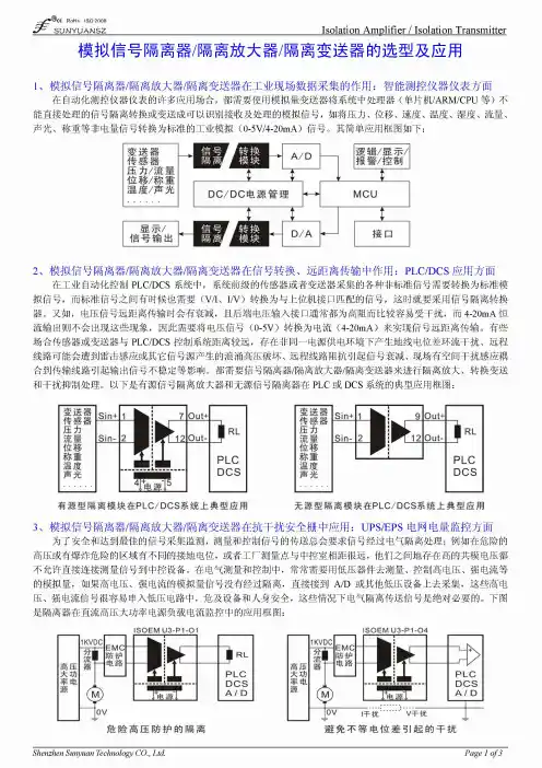
如何选择合适的信号隔离器?信号隔离器选购注意事项信号隔离器是一种信号隔离装置,将输入单路或双路电流或电压信号,变送输出隔离的单路或双路线性的电流或电压信号,并提高输入、输出、电源之间的电气隔离性能。
信号在传输过程中会遇到各种各样的干扰,为保证信号稳定,使用信号隔离器尤为重要。
那哪个牌子的信号隔离器好?如何选购到抗干扰能力强、质量又好的隔离器呢?隔离器的选型应该根据现场仪表、控制系统或二次仪表的接口进行,目前自动化行业输入/输出信号的标准为:4~20mADC或者1~5VDC,当然也有一些特殊的输入/输出信号。
按照仪器仪表的接口分为:信号隔离类;一入多出隔离类;配电类;一入多出配电类;温度隔离变送类;无源隔离类;二线制隔离类;二线制配电类;二线制温度隔离变送类等类型。
在隔离器选型时除了要确定隔离器的功能、适应前后端接口外,还有精度、输出纹波、温度漂移、功耗、响应时间等许多参数需要谨慎选择,具体注意事项如下:1、精度隔离器的精度是非常重要的参数,精度的高低直接关系到隔离器能否正常使用。
隔离器的精度体现了隔离器的设计、制造水平。
用户在选用时应该选用精度高的产品。
2、输出纹波对隔离器精度产生影响的参数还有输出纹波。
输出纹波的产生是由于隔离器使用DC/DC电路对隔离器的工作电源进行隔离给隔离器内部电路供电,输入信号也要先使用DC/DC电路调制成交流信号然后经过隔离部分电路进行信号隔离,隔离后的信号经解调后再转换成直流信号输出。
以CPU为核心的隔离器也存在脉冲信号。
隔离器内部存在的这种高频的交流分量,就是产生输出纹波的原因。
这些高频的交流分量它们的频率一般都有几百KHZ、谐波较多,对信号的污染很难完全清除。
如果输出纹波较高,控制系统模拟量输入模板采集到信号的误差就大,对于高速输入的模拟量输入模板更是如此。
所以选择隔离器时应要求输出纹波的峰-峰值越小越好。
顺连电子的各种系列隔离器均采用高效的滤波电路,较好的抑制了输出纹波。

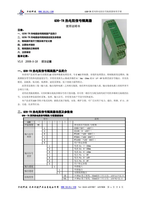
使用说明书目录:一、GDB-TR热电阻信号隔离器产品简介二、GDB-TR热电阻信号隔离器选型及参数表三、隔离器外型尺寸图及端子定义图四、主要技术指标五、隔离器的正确使用六、注意事项版本记录:V1.0 2008-3-18 版本创建一、GDB-TR热电阻信号隔离器产品简介本系列产品采用16位高精度AD采集和数据处理技术、专业MCU控制器、非线性处理算法、特制隔离变送模块,隔离测量各型号的热电阻温度信号,并将其变换为1路或多路的0/4mA~20mA或0/1V~5V标准直流信号输出。
具有高精度、高隔离、低功耗、低漂移、温度范围宽、抗干扰能力强等特点。
此类变送器的三端(输入端、输出端和电源)之间相互隔离,他们所有连接在输入端、输出端或电源上的组件皆不会相互干扰。
采用此类隔离模块,可同时解决现场多路信号的干扰问题,亦可将一路信号分配为相同或不同的多路相互隔离的信号,以实现多种设备同时采集、处理、输入信号,并有效为客户节省空间和成本;本产品采用DIN导轨卡装式结构,插拔式端子接线,安装、维护方便,可广泛应用于电力、通信、铁路、矿山、冶金、交通、仪表等行业。
二、GDB-TR热电阻信号隔离器选型及参数表GDB-TR系列热电阻信号隔离/分配器型谱表GDB-TR热电阻信号隔离器型号及参数表 (在标准条件下测试):注:输出信号类型x代码含义请参见选型表相关内容定货型号应包括:传感器类型、输入/输出规格(标称值)、电源等;三、隔离器外型尺寸图及端子定义图1.外型尺寸图(单位:mm)2、隔离器端子定义及接线说明示意图(具体请参照产品标签所示接线图):注:1、如图,热电阻信号从9、10、11端输入,若现场热电阻与隔离器的距离很近,可用2线连接与9、10端子间,将10与11端子短接;2、V+为辅助电源正端,V-为辅助电源地;3、隔离器输入、输出、电源间相互隔离;四、主要技术指标1.输入信号与规格: CU50、CU100、PT100、PT500、PT1000等可选;具体温度范围规格见产品标签;2.精度等级:0~5/10V输出型±0.2%F.S,0/4~20mA输出型±0.5%F.S;3.输出规格:0~20mA、4~20mA、0~5V、1~5V、0~10V等标准直流信号;具体规格见产品标签;4.输出负载能力:电压输出型5mA;电流输出型≤350Ω;5.输出纹波:≤10mV(有效值,额定输出负载时);6.响应时间:≤300ms;7.隔离耐压:电源、输入、输出间,1500V DC,1min;8.环境温度:-10℃~+60℃;9.温度漂移:≤150PPM(-10℃~+60℃范围内)10.辅助电源:24VDC±10%;具体规格见产品标签;11.电源消耗电流:≤40mA/60mA;五、隔离器的正确使用1.隔离器的安装本型号隔离器采用标准DIN35导轨卡式安装,使用方便。
4-20mA信号隔离器(小体积)如何挑选模拟信号变送器/隔离器?如今,市面上信号变送器品牌众多,许多消费者在选购的时候很容易挑花眼,同时也容易纠结。
那么,消费者到底应该如何挑选信号变送器呢?今天,专注于工业控制产品研发设计生产的高新技术企业——贝福小编为您解答解答。
如何挑选信号变送器?1、选择与压力介质相匹配的信号变送器由于众多的物体都会产生压力,所以朋友们在选择的时候还需要注意选择和压力介质相符合的仪表,以此来保障信号变送器能够在相关的场合得到有效的使用。
例如,黏性的液体、大面积的泥浆有很大可能会堵上压力接口,这时候就需要选择有过滤性的信号变送器,或者为其安装过滤网。
而有些溶剂或许带有腐蚀性,则不可以与变送器进行直接的接触,需要进行防腐蚀装置。
2、信号变送器的压力值选择宜大不宜小在众多的压力系统中,尤其是液压和水压在运行的过程中所产生的峰值具有巨大的不稳定性,容易上下波动,因此就需要选择一款比压力最大值更高一些的信号变送器,以此来保障压力峰值不会一下产生过大的压力。
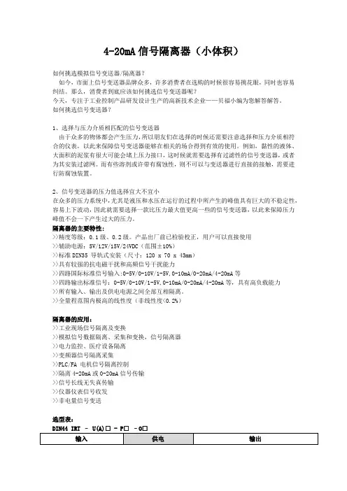
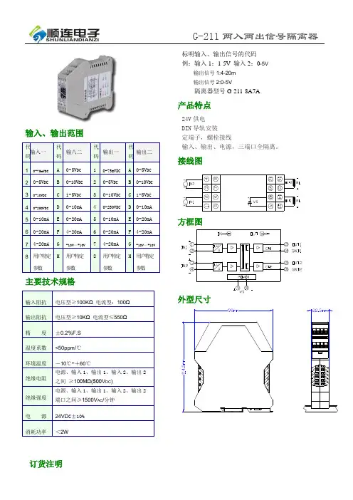
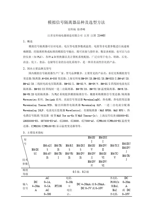
隔离器的主要特性:>>精度等级:0.1级、0.2级。
产品出厂前已检验校正,用户可以直接使用>>辅助电源:5V/12V/15V/24VDC(范围±10%)>>标准DIN35 导轨式安装(尺寸:120 x 70 x 43mm)>>具有较强的抗电磁干扰和高频信号干扰能力>>四路国际标准信号输入:0-5V/0-10V/1-5V,0-10mA/0-20mA/4-20mA等>>四路输出标准信号:0-5V/0-10V/1-5V,0-10mA/0-20mA/4-20mA等,具有高负载能力>>所有输入、输出及供电电源之间全部互相隔离。
>>全量程范围内极高的线性度(非线性度<0.2%)隔离器的应用:>>工业现场信号隔离及变换>>模拟信号数据隔离、采集和变换,信号隔离器>>电力监控、医疗设备隔离>>变频器信号隔离采集>>PLC/FA 电机信号隔离控制>>隔离4-20mA或0-20mA信号传输>>信号长线无失真传输>>仪器仪表信号收发>>非电量信号变送选型表:DIN44 IRT – U(A)□ - P□–O□产品最大绝对额定值:Continuous Isolation Voltage (持续隔离电压):3000VDC Junction Temperature (工作温度):+85℃ Storage Temperature (存贮温度):+150℃ 电源电压范围:±10%Vin注意:如果超出上述范围,产品可能会引起永久性损坏。
交流信号隔离器的参数和特点交流信号隔离器是一种常用的电子元器件,可以有效地隔离交流信号,提高信号传输质量。
本文将介绍交流信号隔离器的参数和特点。
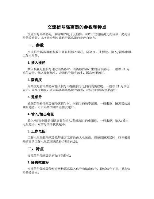
一、参数交流信号隔离器的参数主要包括插入损耗、隔离度、通频带、输入/输出电阻、工作电压等。
1. 插入损耗插入损耗是指信号通过隔离器时,隔离器内部产生的信号损耗,一般以dB为单位表示。
插入损耗越小,表示信号损失越小,隔离效果越好。
2. 隔离度隔离度是指隔离器对输入信号与输出信号之间的隔离程度,一般以dB为单位表示。
隔离度越高,表示隔离器隔离能力越强,对信号的隔离效果越好。
3. 通频带通频带是指隔离器在隔离信号时,对信号的频率范围。
一般来说,隔离器的通频带越宽,可以隔离的频率范围就越广。
4. 输入/输出电阻输入/输出电阻是指隔离器在输入/输出端口的电阻值。
一般来说,输入/输出电阻越小,对信号的干扰就越小。
5. 工作电压工作电压是指隔离器能够正常工作的最大电压值。
在使用隔离器时,应该根据隔离器的工作电压范围来选择合适的电源。
二、特点交流信号隔离器具有如下的特点:1. 隔离效果好交流信号隔离器能够有效地隔离输入信号和输出信号,降低信号干扰、提高信号传输效率。
2. 通用性强交流信号隔离器适用于多种场景,如电力系统、工控系统、通讯系统、仪器仪表等,具有很强的通用性。
3. 安装简便交流信号隔离器通常具有小体积、轻便的特点,安装也十分简便。
4. 维护成本低交流信号隔离器的维护成本低,可以长时间稳定工作,不需要定期更换零部件,降低了使用成本。
三、总结交流信号隔离器是一种十分实用的电子元器件,能够有效地提高信号传输质量,具有插入损耗小、隔离效果好、通用性强、安装简便、维护成本低等特点。
在实际应用中,应该根据需要选择合适的隔离器,提升信号传输效率,保障系统的稳定运行。
信号隔离器选型标准:
信号隔离器的选型标准主要包括以下几个方面:
输入输出信号类型:根据实际需求选择合适的输入输出信号类型,如4-20mA、0-10V、0-5V等。
隔离方式:根据需要选择不同的隔离方式,如光电隔离、磁隔离、电容隔离等。
精度等级:根据实际需求选择合适的精度等级,以满足信号的传输精度要求。
供电电源:根据实际情况选择合适的供电电源,如直流电源、交流电源等。
接口类型:根据实际需求选择合适的接口类型,如接线端子、插头插座等。
防护等级:根据实际需求选择合适的防护等级,以确保信号隔离器在恶劣环境下的稳定性和可靠性。
品牌和质量:选择知名品牌和质量可靠的产品,以确保信号隔离器的性能和使用寿命。
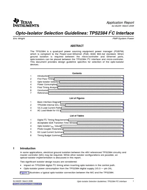
1Introduction Application Report SLVA229–March2006Opto-Isolator Selection Guidelines:TPS2384I2C Interface Eric Wright PMP/System PowerABSTRACTThe TPS2384is a quad-port power sourcing equipment power manager(PSEPM)which is compliant to the Power-over-Ethernet(PoE)IEEE802.3af standard.Whenground isolation is required between the micro-controller and Ethernet ports,opto-isolators can be placed between the TPS2384I2C interface and micro-controller.This document provides design guideline specifics for selection of the opto-isolatordevices.Contents1Introduction (1)2First Pass Timing (2)3Opto-Isolator Selection (4)4Power Consumption (5)5Final Timing Analysis (7)6Conclusion (8)7References (8)List of Figures1Basic Interface Diagram (2)2TPS2384Internal SCL Delay (4)3V3.3Load Current Paths (5)4AC Load Model for V3.3 (7)List of Tables1Digital I2C Timing Requirements (2)2Acceptable SDA Transition Time Window (3)3Opto-Isolator t PHL Values (4)4Photo-Coupler Parameters (5)5DC Load Current Summary (6)6Timing Budget Summary (8)In some applications,electrical ground isolation between the48V referenced TPS2384circuitry andmaster controller(MC)may be required.While other isolator configurations are possible,anoptical-isolator implementation is discussed in this report.Two significant isolator design issues are considered:•Impact on TPS2384digital I2C timing when inserting opto-isolators in the control path.•Opto-isolator power consumption from the TPS2384digital supply(V3.3—pin24).Figure1illustrates a typical opto-isolator connection between the MC and the TPS2384.SLVA229–March20061Opto-Isolator Selection Guidelines:TPS2384I2C Interface[5:1](5x )2First Pass TimingFirst Pass TimingFigure 1.Basic Interface DiagramThe TPS2384data sheet digital I 2C timing requirements are summarized in Table 1.These timingrequirements mirror the requirements for fast mode (F/S)devices outlined I 2C specification.The opto-isolator propagation delay characteristics can constrain and possibly necessitate alteration of the MC output timing requirements.Table 1.Digital I 2C Timing RequirementsPARAMETERTEST CONDITION MIN TYP MAX UNITS SCL clock frequency 0400kHz SCL high 0.6Pulse duration µsSCL low1.3Rise time,SCL to SDA 0.3µs Fall time,SCL to SDA 0.3µs Setup time,SDA to SCL 0.25µs Hold time,SCL to SDA0.30.9µs Bus free time between start and stop 1.3µs Setup time,SCL to start condition 0.6µs Hold time,start condition to SCL 0.6µs Setup time,SCL to stop condition 0.6µs Delay time,SCL to SCL INT ,t d(SCL)0.5(1)0.9(1)µs(1)t d(SCL)is the TPS2384internal clock delay.2SLVA229–March 2006Opto-Isolator Selection Guidelines:TPS2384I 2C Interface2.1SCL/SDA_I Setup and Hold Considerations 2.2SDA_O Timing Considerations First Pass TimingSelection of the opto-isolator type should also consider end to end signal polarity and MC output drivetype.The circuit in Figure1implements inverting opto-isolators for the SCL and SDA_I inputs but since the MC drives the LED cathode;no net polarity inversion takes place.Also of note in Figure1is the SDA_O signal drive implementation.To minimize V3.3loading,the SDA_O signal derives its LED anode drive current from V48.Since this drive implementation induces a polarity change,an inverter is required between the opto-isolator output and the MC.This inverter must be anopen drain type to be compatible with the I2C specification and have minimal impact on timing.The zener diode Vz(5.6V),adds a layer of voltage protection to the opto-isolator LED and SDA_O.R48should be chosen with power dissipation(1/2W)and LED bias current in mind.The I2C standard states that SDA_I must be stable during the SCL logic high time(including SDA_I setup and hold times),or in other words SDA_I can only change state when SCL is a valid low.t trans is theallowable SDA_I state transition time window(during SCL low)and bounds the rising and falling edgepropagation delay requirements of the opto-isolators.Table2shows t trans for minimum and maximum hold times,t h.t trans=t low–t su(min)–t hTable2.Acceptable SDA Transition Time Windowt trans(µs)t low(µs)t su(µs)t h(µs)0.75 1.30.250.30.15 1.30.250.9In general,if the rising and falling edge propagation delays of the SCL and SDA_I opto-isolators trackeach other,are sufficiently small,and the MC meets the requirements of the I2C standard,then inputsignal timing can be met.Similarly,start,restart,and stop conditions have setup and hold requirements of t stop/start=0.6µs which should also be considered.The TPS2384internal SCL delay,t d(SCL)should be considered for device reads.SDA_O transition timing occurs on the falling edge of the TPS2384internal SCL signal as illustrated in Figure2.The SDA_Oopto-isolator is restricted to faster devices so that data arrives at the MC within the required setup andhold times.t d(SCL),t PLH(SCL),t PHL(SCL),and t su(MC)delays bound opto-isolator propagation delays on theSDA_O signal.Also note that the SDA_O opto-isolator(and inverter)are powered by V3.3-EXT and do not impact V3.3loading.SLVA229–March20063Opto-Isolator Selection Guidelines:TPS2384I2C Interface3Opto-Isolator SelectionOpto-Isolator SelectionFigure 2.TPS2384Internal SCL DelayTable 3shows target t PHL (total sum for SCL and SDA_O opto-isolators)values that can be derived from the following equations.t h(min)<t PHL +t d(SCL)<t h(max)t h(min)–t d(SCL)<t PHL <t h(max)–t d(SCL)andt PHL +t d(SCL)<t low –t su t PHL <t low –t su –t d(SCL)Table 3.Opto-Isolator t PHL ValuesCONSIDERING SDA_O HOLD REQUIREMENTS CONSIDERING SDA_O SETUP REQUIREMENTS t PHL (µs)t h (µs)t d(SCL)(µs)t PHL (µs)t su (µs)t d(SCL)(µs)>–0.20.30.5<0.550.250.50>–0.60.30.9<0.150.250.90<0.40.90.5<0.00.90.9For the SCL and SDA_I signals,a medium-fast,low power,dual opto-isolator configuration is desired.For the SDA_O signal,a fast,medium power,single opto-isolator is desired,and for the low speed MS and PORB signals,a slow,low power,dual opto-isolator configuration is desired.Three NEC Electronics photo couplers were selected and the relevant details are summarized in Table 4.4SLVA229–March 2006Opto-Isolator Selection Guidelines:TPS2384I 2C Interface4Power Consumption[5:1](5x )Power ConsumptionTable 4.Photo-Coupler ParametersNEC Electronics Configuration I CCL(typ)t PLH(min)(1)t PLH(typ)t PLH(max)t PLH(min)(1)t PHL(typ)t PHL(max)Device Number PS8802-2Dual (MS,PORB)200µA 0.1µs 0.6µs 1.2µs 0.1µs 0.3µs 0.8µs PS8821-2Dual (SCL,SDA_I)200µA 0.1µs0.5µs 0.9µs 0.1µs0.3µs 0.6µs PS9821-1(2)Single (SDA_O)7mA50ns100ns45ns100ns(1)t PLH(min)and t PHL(min)are estimates for this report and are not data sheet specified.(2)PS9121is an acceptable substitute for the PS9821.It might be noted that the propagation delay times are a bit high for the SCL/SDA_I device.The impact of these values are evaluated in the final timing analysis.The I 2C interface support circuitry for the TPS2384can be powered from the V3.3pin if limited to less than 3mA peak.Exceeding the peak output current can cause internal digital circuit malfunction due to short circuit limiting of the V3.3output.Excessively high DC currents should be evaluated with respect to power dissipation.The V3.3pin load current paths are highlighted in Figure 3.Included is loading by the 5address lines,4opto-isolator output pullup resistors,and the 4opto-isolator output amplifiers.Figure 3.V3.3Load Current PathsSLVA229–March 20065Opto-Isolator Selection Guidelines:TPS2384I 2C Interface4.1DC ConsiderationsV 3.3(max) R INT ńNR INT ńN )R3u V TH(max)+V TH(nom))V HYSTLet :R INT +0.8 R INT(nom)+40k W ,N +Number of TPS2384Devices R3tR INT NƪV 3.3(min)V TH(max)*1ƫFor N +2,R3tǒ40k 2Ǔ ǒ31.65*1Ǔ+16.4k W I 3.3(max)(R1&R2)+3mA *I opto *I addr *I R3ńR4I 3.3(max)(R1&R2)+3mA *400m A *50m A *404m A +2.1mA R1ńR2uV3.30.5 I 3.3(max)(R1&R2)+3.30.5 2.1mA+3.1k W For V3.3(max)+3.7V,R1ńR2u 3.5k W4.2AC ConsiderationsPower ConsumptionR3/R4:Select a value for these resistors based on MS/PORB threshold of 1.5V (and 150mV hysteresis)and the MS/PORB internal 50-k Ωresistor pull-down (R INT ).R1/R2:Select R1/R2for simultaneous SCL/SDA_I low (for V3.3output current)and minimize R1/R2forrise time signal considerations.Table 5summarizes the DC load requirement targets.Table 5.DC Load Current SummaryV3.3=3.3VLoad Target I LD Target R PUAddress 50µA PS8821-2200µA PS8802-2200µA R1 1.05mA 3.1k ΩR2 1.05mA 3.1k ΩR3202µA 16.4k ΩR4202µA 16.4k ΩI SUM =3.0mABulk energy storage capacitance:Determine beneficial effects of V3.3capacitance which sources current peaks during simultaneous logic low conditions.Considering V3.3(V S )with series source impedance R S ,minimum R L (R1||R2)can be determined so that V3.3does not fall below 1.65V (V TH +V HYST )during simultaneous logic low (with I S =2.1mA).Figure 4shows the circuit model.R L =R S =1.65V/0.0021=786Ω6SLVA229–March 2006Opto-Isolator Selection Guidelines:TPS2384I 2C InterfaceR L786WU1TCLOSE = 100sm t low(max)+2R L C1t low(max)+4R C1:R+R LŦR S+R L2C1(min)+t low(max)2R L+6m s2786+3.82nFR L+R1ŦR2;R1(min)+R2(min)+2RL+2786+1572W5Final Timing AnalysisFinal Timing Analysis Figure4.AC Load Model for V3.3Target C1value required to keep V3.3above1.65V during U1on time:For I2C bus speed=100kHz,t low(max)=6µs(very fast rise/fall times)Target4×τ(98%droop)=t low(max)This shows that a significantly small C1is adequate to support V3.3during relatively slow I2C bus access.A reasonable bypass capacitor value of0.1µF located at the V3.3pin of the TPS2384and at each pin ofthe dual opto-isolators provides good AC voltage stability.Assuming C1=0.3µF and R1=R2=1572Ω, yields t low(max)=472µs.This equates to a minimum I2C bus access speed of1.27kHz.So,targeting R1 and R2values between the minimum AC value(1572Ω)and the minimum DC value(3.1kΩ)provides good AC and DC performance.The designer must keep in mind that the timing parameters detailed in Table4and used in Section5are based on I F(set by RD in Figure1and Figure3)and R L(R1,R2,R3,R4in Figure1and Figure3)values specified in the opto-isolator manufacturers data sheet.Deviation from these values will have an impact on timing and must be evaluated.MC writes must meet the TPS2384setup and hold times by synchronizing data transitions to occur within the acceptable data transition window outlined in Section2.1.MC reads from the TPS2384must meet the MC setup and hold times as outlined in Section2.2.The following equations define the acceptable data transition window times(during SCL low)for reads and writes.Read Access(400kHz SCL,t0at SCL rising edge):t accept1=t high+t h(max)t accept2=t period–t su(MC-min)Write Access(400kHz SCL,t0at SCL rising edge):t accept1=t high+t h(max)t accept2=t period–t su(2384-min)NOTE:Rise and fall times are ignored here but must be considered by the designer.Table6illustrates the impact of timing parameter variations during reads and writes.t MC represents the delay variability that must be accounted for when designing SCL/SDA timing.Designers should target the data transitions to occur within the acceptable time windows,t accept1and t accept2for each condition.SLVA229–March20067Opto-Isolator Selection Guidelines:TPS2384I2C Interface6Conclusion7ReferencesConclusionTable 6.Timing Budget SummaryReads Min 0.10.60.10.5t h =0.9Max 0.9 1.20.60.9t o t PLH t high t PHL t d t p-opto2t mc t accept1t accept200.10.60.10.50.1 1.4 1.5 2.400.10.60.10.90.1 1.8 1.5 2.400.10.60.60.50.1 1.9 1.5 2.400.10.60.60.90.1 2.3 1.5 2.400.1 1.20.10.50.12 2.1 2.400.1 1.20.10.90.1 2.4 2.1 2.400.1 1.20.60.50.1 2.5 2.1 2.400.1 1.20.60.90.1 2.9 2.1 2.400.90.60.10.50.1 2.2 1.5 2.400.90.60.10.90.1 2.6 1.5 2.400.90.60.60.50.1 2.7 1.5 2.400.90.60.60.90.1 3.1 1.5 2.400.9 1.20.10.50.1 2.8 2.1 2.400.9 1.20.10.90.1 3.2 2.1 2.400.9 1.20.60.50.1 3.3 2.1 2.400.91.20.60.90.13.72.12.4Writes Min 0.10.60.1t h =0.9Max 0.9 1.20.6t o t PLH t high t PHL t mc t accept1t accept200.10.60.10.8 1.5 2.2500.10.60.6 1.3 1.5 2.2500.1 1.20.1 1.4 2.1 2.2500.1 1.20.6 1.9 2.1 2.2500.90.60.1 1.6 1.5 2.2500.90.60.6 2.1 1.5 2.2500.9 1.20.1 2.2 2.1 2.2500.91.20.62.72.12.25This application of opto-isolator interface to the TPS2384has been implemented for use with the MSP430micro-controller.In all cases,the MC operating characteristics should be studied carefully and in some cases tailored to meet I 2C bus timing requirements.This may require SCL duty cycle adjustment and/or SDA transition time adjustment with respect to SCL.In some cases,this can be accomplished by slowing the I 2C bus speed to less than 400kHz;however,this bus speed slowdown may limit the total number of controllable ports in larger systems.1.TPS2384,Quad Integrated Power Sourcing Equipment Power Manager2.TPS2384,Users Guide3.I 2C Bus Specification8SLVA229–March 2006Opto-Isolator Selection Guidelines:TPS2384I 2C InterfaceIMPORTANT NOTICETexas Instruments Incorporated and its subsidiaries (TI) reserve the right to make corrections, modifications, enhancements, improvements, and other changes to its products and services at any time and to discontinue any product or service without notice. Customers should obtain the latest relevant information before placing orders and should verify that such information is current and complete. All products are sold subject to TI’s terms and conditions of sale supplied at the time of order acknowledgment.TI warrants performance of its hardware products to the specifications applicable at the time of sale in accordance with TI’s standard warranty. Testing and other quality control techniques are used to the extent TI deems necessary to support this warranty. Except where mandated by government requirements, testing of all parameters of each product is not necessarily performed.TI assumes no liability for applications assistance or customer product design. Customers are responsible for their products and applications using TI components. To minimize the risks associated with customer products and applications, customers should provide adequate design and operating safeguards.TI does not warrant or represent that any license, either express or implied, is granted under any TI patent right, copyright, mask work right, or other TI intellectual property right relating to any combination, machine, or process in which TI products or services are used. Information published by TI regarding third-party products or services does not constitute a license from TI to use such products or services or a warranty or endorsement thereof. Use of such information may require a license from a third party under the patents or other intellectual property of the third party, or a license from TI under the patents or other intellectual property of TI. Reproduction of information in TI data books or data sheets is permissible only if reproduction is without alteration and is accompanied by all associated warranties, conditions, limitations, and notices. Reproduction of this information with alteration is an unfair and deceptive business practice. TI is not responsible or liable for such altered documentation.Resale of TI products or services with statements different from or beyond the parameters stated by TI for that product or service voids all express and any implied warranties for the associated TI product or service and is an unfair and deceptive business practice. TI is not responsible or liable for any such statements. Following are URLs where you can obtain information on other Texas Instruments products and application solutions:Products ApplicationsAmplifiers Audio /audioData Converters Automotive /automotiveDSP Broadband /broadband Interface Digital Control /digitalcontrolLogic Military /militaryPower Mgmt Optical Networking /opticalnetwork Microcontrollers Security /securityTelephony /telephonyVideo & Imaging /videoWireless /wirelessMailing Address:Texas InstrumentsPost Office Box 655303 Dallas, Texas 75265Copyright 2006, Texas Instruments Incorporated。
分享专业智慧,相聚电气天下信号隔离器选型信号隔离器模拟信号接口模块MCR为此提供了简便的就急措施,它可以对这类失真进行补偿.它们对信号进行电隔离并且消除测量回路之间的藕合.下列产品可供选用:*标准的三端隔离放大器,输入端、输出端和供电部分之间相互电隔离。
*馈电隔离器,用于两线或者三线现场测量变送器的馈电和信号传输。
*无源隔离器,用于电隔离,而不需要辅助电源。
除了电隔离外,在隔离放大器中信号另外还得到放大,以便实现长距离的传输或者连接高阻抗的负载。
信号传输的其它任务是对叠加在测量植上的干扰信号进行滤波,以及根扰控制器所要求的输入量进行匹配。
因此,隔离、放大、滤波和匹配是结构紧凑的MCR隔离放大器所起的作用。
温度转换温度是工业控制过程中需要监视和处理的关键参数之一。
有两种测量技术已经得到广泛使用:热敏电阻(例如PT100、NI1000)是电阻值随温度变化的电阻MCR温度测量变送器测量这一电阻值,并且对电阻值进行线性化处理以及把它转换成同温度成正比的模拟信号。
同热敏电阻形成鲜明对照的热电偶则是一种电压。
所谓的冷端补偿则负责把测得的差值温度转换成绝对温度MCR温度测量变送器具有组态功能,从而可以针对相应的应用场合进行调整匹配。
这类产品范围包括:分享专业智慧,相聚电气天下*温度测量变送器,用于所有常见的热敏电阻(PT100、NI1000)和热电偶(J、K型)*PT100温度测量变送器,用于PT100传感器。
信号转换MCR模块把不同的信号参数转换成控制器所要求的模拟信号,并且以此对各重要的过程参数进行匹配。
各种信号波形的电流,如果数值范围在0.5A至5A之间,将通过MCR电流测量变送器转换成模拟的标准信号,以便进行监视.各种电压以及频率、转速和电位器位置也都可以按照控制层的要求得到匹配。
上述信号参数将通过相应的MCR模块非常精确地得到转换,并且安全可靠地传递给控制器。
用于信号转换的产品范围包括:*有源的真有效值电流测量变送器。
隔离器如何选型-数字隔离器选型步骤(总4页)--本页仅作为文档封面,使用时请直接删除即可----内页可以根据需求调整合适字体及大小--隔离器如何选型?数字隔离器选型步骤是,不知如何去选择一个合理的、适用的隔离器。
前两天,记者采访了ADI公司数字隔离器产品高级应用工程师周晓奇,他就有关隔离器在电路中的作用、工程师在数字隔离器选型时应该注意哪些步骤等问题,给电子工程师们一个很好的解答。
为什么要用隔离器隔离器主要是用在隔离高压(危险电路)系统和低压(安全电路)系统之间的电气连接,以保护用户以及电路系统安全,以及隔离敏感电路(比如高精度检测电路)和噪声源(例如大功率开关电源)之间的连接,以减小噪声干扰。
周晓奇说,隔离器的主要结构大致有四种:一是传统光电耦合; 二是集成式变压器(磁耦合);三是集成式电容耦合; 四是分立式变压器耦合。
最常用的是光耦合器,光耦合器一般由三部分组成:光的发射、光的接收及信号放大。
输入的电信号驱动发光二极管(LED),使之发出一定波长的光,被光检测器接收而产生光电流,再经过进一步放大后输出。
它的主要优点是单向传输信号,输入端与输出端完全实现了电气隔离,抗干扰能力强,使用寿命长,传输效率高。
它广泛用于电平转换、信号隔离、级间隔离、开关电路、远距离信号传输、脉冲放大、固态继电器(SSR)、仪器仪表、通信设备及微机接口中。
随着近几年数据传输的速度不断提升,传统的光耦合器也暴露出一些缺点,例如,整个电路体积大,集成度不高,而且光电耦合器件本身具有易损耗、速度较慢(一般的数据速率低于1Mbps)、耗电量大等缺点,特别是在温度和老化变化过程中的性能极不稳定,为其应用带来局限,特别是在工业应用中这些问题就比较突出。
为了克服光电隔离技术的诸多缺点,许多半导体公司开始研发不发光的隔离器解决方案。
周晓奇告诉记者,ADI 公司是最早一家推出新型数字隔离器解决方案的公司,并于2001年率先推出基于其专有iCoupler磁耦隔离技术的标准数字隔离产品。