液压扭力扳手使用说明书
- 格式:pdf
- 大小:15.24 MB
- 文档页数:27
液压扭力扳手操作说明书前言亲爱的用户:在利用该扭力扳手器具前,建议您认真学习这些指导条款。
ITH GmbH的扭斩扳手工具是按DIN ISO 9001标准进行设计与加工的。
平安方面遵循CE标准规定的要求。
超级感激他们的先进设计,ITH扭力扳手利用平安操作间单。
但是,在操作利历时,有很多事项必需注意。
基于那个缘故,请确信所有利用该设备工作的人员,都阅读过而且明白得参数表格的第七章节的内容,其题目为“平安注意事项”。
:++49/(0)291/9962-0:++49/(0)291/9962-11目录章节内容文件1.0 扭力扳手(收发)地址及(技术)参数。
2.0 EEC认证。
3.0 实验报告。
4.0 扭力值表格。
5.0 扭力扳手(组合体)操作指导。
6.0 简明操作指导。
7.0 平安注意事项。
8.0 高压泵备用部件清单。
9.0 高压泵备用部件图。
10.0 扭力扳手备用部件图及部件清单。
11.0 扭力值显示表操作指导。
10.0 扭力扳手压力与扭力参数。
11.0 备用部件及附属部件。
注意事项:这些指导条款是按DIN8418标准VCMA-相关文件确立的。
若是您在具体需要时,对本文要求进行补充,欢迎您的建议。
专门针对幸免意外事故的发生。
1.0 扭力扳手组合体的大体参数表格1.1 (供发)地址:1.1.1 制造方:ITH GmbH1.1.2 购买方:Voith Siemens Hydro GmbH & Co. KG1.1.3 交货日期:04/12/011.2 扭力扳手组合体技术参数1.2.1 扭力扳手1.2.2 压力站1.2.3 软管1.2.4 连接配件1.2.5 弯管接头2.0 EC认证2.0 实验装置3.0 校对:A:扭臂长度:1米 D:实验力矩:B:试重重量:50千克 E:显示值按转换因素换算C:读出数值:2774.0 显时值表格注明:5.0 扭力扳手操作说明5.1 连接主电源时,用EEC连接部件的插头插入,确信有效电源有三相,并有一个接地(230伏单相交流,只用一相有效电源)。

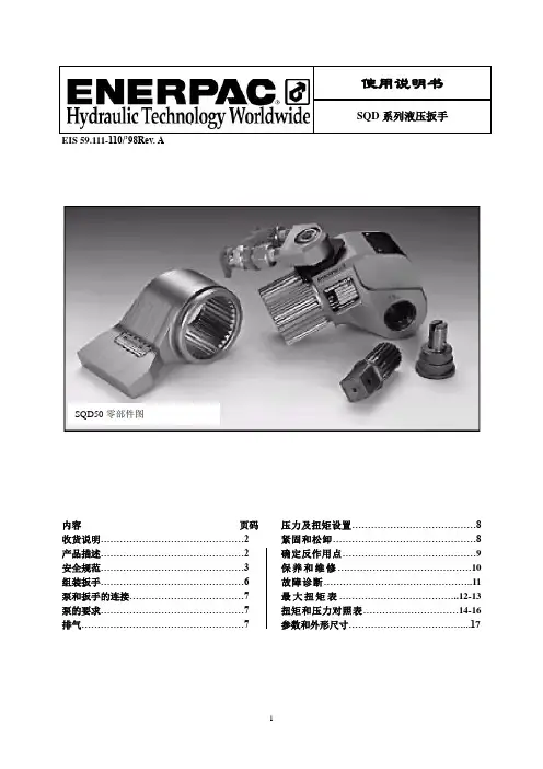
操作说明YD系列驱动轴液压扳手◊应用成功源自专业服务目录I收件提示(开箱检查)................................. . (2)II安全指南 .............................................. .3皿关于液压扳手 (6)IV操作使用 (7)V关于液压泵 (10)W 扳手及泵的保养和修.................................. ・・11表1:螺栓预紧力推荐表.. (13)表2:液压扭矩扳手压力一一扭矩对照表 (14)I收件提示(开箱检查)仔细检查产品有无损坏。
如果发现因货运受损,应及时向货运商申报;运输损坏不包括在质量保证之内,货运商有责任承担修理或调换损坏物品的费用。
液压扭矩扳手是一种动力工具,使用前应仔细阅读所有的说明、警告和注意事项,遵守安全措施以避免在操作设备时发生人身或设备的损伤!我们对因为不安全操作及错误操作导致的损坏不负责。
II安全指南扭力扳手是动力工具,对任何动力工具而言,确实、可靠的安全预防工作均是非常重要的,以下就是需要注意的几点建议:•仔细阅读所有技术文件。
•尽量使工作环境干净、明亮。
如果工作场地的大气环境有任何潜在的爆炸可能,则不可使用电动泵,应使用气动泵。
如有金属撞击产生火花,应采取预防措施。
•反作用力臂需要正确的反作用力,调整反作用力臂或反作用面。
•避免工具(扳手)误操作泵的操作遥控板只是为扳手操作者使用,避免使操作者和泵分隔太远。
•保证操作空间扳手在使用中大部分是不用手扶的,如果在必须用手扶或固定扳手的情况下,应想其它办法达到目的。
•避免触电确保用电动泵时电源的接地良好及适当的电压。
•扳手不用时应保存好暂时不用的扳手和扳手附件应妥善保存,避免损坏。
• 使用适合的扳手不用小扳手或附件来代替大扳手的工作,不用不适合的扳手进行工作。
• 使用合适的安全服饰当使用手动/ 机动液压设备时,应使用手套、安全帽、安全鞋、护耳,以及其它劳防服饰。
ALTE AT系列液压扳手使用说明使用扳手注意事项此扳手是以电动液压泵为动力源。
使用相同压力和扭矩的设备。
此液压扳手只能使用最大压力在10000帕斯卡(681巴)的液压泵。
使用两根最大压力等级为10000帕斯卡(681巴)的管子。
禁止交换扳手上的雄性、雌性螺旋入口或管子一端的连接设备。
禁止使用破损的、磨损的或坏掉的管子,使用前确认管子上没有裂纹、裂痕和漏洞。
使用快速连接系统使管子分别连接扳手和泵。
确认装有弹簧固定环已经完全套好,安全环已经紧紧套在装有弹簧的固定环上以防止连接装置在压力下断开。
当连接管没有预载液压油时,确认液压泵的油箱在开动时没有排出液压油。
禁止移动任何商标,或更换任何损坏的商标。
禁止用手握住已经加压的管子。
在压力下溢出的油会渗透皮肤,造成严重伤害。
如果被灼伤,请立即去医院处理。
禁止只使用一根加压油管,必须同时使用液压设备配套的两根油管。
在操作扳手或对其进行保养维护时,必须佩戴眼部保护工具。
在操作扳手时必须佩戴头部和手部保护工具和防护罩。
在操作过程中必须使手、松散的衣服和长发远离反作用力臂和工作区域。
在操作过程中不必尝试用手去撑扳手。
此种扳手会产生强大的反作用力。
使用合适的机械支撑和正确的反作用力臂的位置来控制反作用力。
不要将反作用力臂的位置摆放在使扳手倾斜于螺栓轴的位置,也禁止用旋转的物体作为作用力支撑。
禁止将反作用力臂当做固定把手使用。
在使用时务必确认操作者的手没有被夹在作用力臂和固定物体之间。
禁止强力的弯曲和纠结管子,这会导致压力回转,过早的使管子失去效力。
禁止使用管子来拖曳机器。
使用液压扳手原厂配件。
使用冲压的套筒和配件,禁止使用手工(铬合金)的套筒或配件。
只能使用与螺栓或螺母配套的套筒和配件,并且确认扳手不能倾斜于螺栓轴。
在设置、重设或调节此工具的任何零件或对此工具进行保养维护之前,保持液压泵处于关闭状态。
此扳手不是电的绝缘体。
当此扳手与带有电源或电线的泵一起使用时,按照泵的说明书将泵放在合适的地面。
TQ340/35Y2HYDRAULIC CASING TONGOPERATION MANUALTQ340-35Y-SMSTANDARD: SY/T 5074-2004PRODUCTION PERMIT:XK14-002-000207K-0048Goldenman Petroleum Equipment Co., Ltd Add:7/F, Wanda International Mansion, 67 Fuqian Street , Dongying ChinaTel:+0086-546-8058779 E-mail:********************CONTENTSSECTION ⅠINTRODUCTIONSECTION ⅡPERFORMANCE PARAMETERSSECTION ⅢINSTALLATIONSECTION ⅣOPERATION INSTRUCTIONSSECTION ⅤMAINTENANCESECTION Ⅵ TROUBLE SHOOTINGSECTION ⅦATTACHED FIGURESSECTION ⅧLUBRICATIONSECTION Ⅸ PRESSURE TORQUE GAUGE AND OIL FILLER SECTION Ⅹ RECOMMENDED SPARE PARTSSECTION Ⅺ HYDRAULIC LIFT CYLINDERSECTION ⅫAPI RECOMMENDED TORQUE FOR 41/2″-133/8″CASINGSECTION ⅠINTRODUCTIONTQ340/35Y2Hydraulic Casing Tong is used to make up and break out for casing operation in oil fields. It greatly reduces the labor of worker, enhances connection quality of thread and diminished accidents in inappropriate casing operation.Features:l. Opening type, convenient and prompt to enter and slide off the working position, with an integral tong head of great strength and rigidity.2. Double swing head jaws, very convenient to assemble and disassemble, with the best design for tangent-diameter ratio, ensuring the reliability of gripping and easy cam- backslide.3. Band brake of great moment, easy to operate and convenient to maintain and replace.4. Notched gear new type sporting structure, greatly improving the strength and rigidity.5. Wholly hydraulic mode. High torque motor of swing cylinder type will supply effective power. The power tong takes mechanical gear changing and its structure is simple and reliable.6. The shell is thickened with Mn. The jaws are cast with precise technology, artistic and strong.7. The hydraulic torque gauge as well as the joint for a round-torque gauge makes it possible for computers to manage the process.SECTION ⅡPERFORMANCE PARAMETERSⅠ. Technical parameters1. Suitable pipe 4"- 133/8" (101.6-340mm)2. Opening size 13.78" (350 mm)3. Head spinning speed high 50-90 rpmlow 8-14 rpm4. Max. torque high 2580-4425 ft.lbf (3.5-6 kN. m)low 16225-27285 ft.lbf (22-37 kN. m)5. Maximum working pressure 2900 psi (20 MPa)6. Working flow 29-45 gpm (110-170 L/min)Max. working flow 52.5 gpm (200 L/min)7. Overall dimensions 62″×35″×42″(1580×900×1060 mm)8. Weight 1650 lb (750 kg)Ⅱ. Speed and Torque Comparison (see Table 1, 2)Table 1 Speed under different flowSpeed (rpm)FlowGPM (L/min)High gear Low gear29(110)487.632 (120)528.337 (140)619.742 (160)701147.5 (180)7812.553 (200)8714Table 2 Max theoretical torque under different pressureTorque ft.lbf (kN.m)PressurePSI (MPa)High gear Low gear1450(10)2212 (3)13275 (18)1740 (12)2580 (3.5)16226 (22)2030 (14)2950 (4)19176 (26)2320 (16)3540 (4.8)22126 (30)2610 (18)3982 (5.4)24340 (33)2900 (20)4425 (6)27290 (37)SECTION ⅢINSTALLATIONⅠHang the tong (see Fig.4)l . Fix the single pulley (3.3 US ton) under beam of the crown block.2. Get a wire rope (at least 1/2") through the pulley, with one end fixed on the base beam. The height of the tong should be at the same level as the average height of joint during making up and breaking out casing.ⅡLevel the tongThe tongs must be leveled when hung up, or the dies will be sliding to grip.Front and back level - adjust the two screws at the joint where the tong is connected with their hanger.Crosswise level - turn the screw rod at the top of the hanger.ⅢConnect the rear wireThe wire, at least 5/8", is connected with the ring of the torque cylinder at the end of the tongs, the other end fixed on the derrick or the drilling platform.NOTE:When the wire rope is tightened, it should be almost at the same level of the tongs, and be at an angle of 90°from the tong medium line.ⅣFill the torque oil cylinderWhen the piston rod is pulled out 30mm long, oil must be filled. Use the hand-oiling pump equipped with the tong to oil the torque cylinder until the hand of torque gauge acts.ⅤConnect the pipesHigh pressure oil hose – NPT1 or M30*l.5 joint connects with high-pressure hose from the power unit.Low-pressure return hose – NPT11/4 or M42*2 joint connects with low-pressure hose from the power unit.Drain hose – M18*l.5 joint connects with the small return line from the power unit. SECTION ⅣOPERATIONⅠRequirements1. Know the tong structure and the properties.2.Know the use of the hydraulic hand-reversing valve and of the speed-changing handle.3.Know the operation sequence and safety requirements.4. Know the functions of the meters.ⅡPreparation for the operation .1. Install the jaws that go with the casing pipe. Note that the two jaws should be installed correctly.2. Put the handles of the hydraulic hand-reversing valve and the speed-changing handle at neutral position.3. Start the hydraulic power unit.4. Push or pull the handle of the hydraulic hand-reversing valve, and you will hear the hydraulic motor while the tong head notched gear remains still.5. Set the handle of the speed-changing handle at high or low gear. Push or pull the handle of the hydraulic hand reversing valve, and the notched gear turns smoothly in forward and reverse direction.Attention: Do stop the tong when change gear.Ⅲ Working process1. Align the gear’s notch with the jaw rack’s notch.2. Set the backing pin into “make up” or “break out” hole, and adjust the brake band.3. Align the gear notch with the case notch.4. Draw the safety door open, push the tongs to working position and close the door. *Making upa. High gear operation: Set the handle of speed-changing handle at high speed position and the handle of hydraulic reversing valve at “make up” position. Jaws clamp the casing tightly and drive the casing rotate in “make up” direction. At the same time watch the torque gauge. If the reading fails to reach the needed value, change to low gear.b. Low gear operation: Stop the motor and put the speed-changing handle at low gear, and operate the direction-reversing valve, the casing pipe will turn slowly. Watch the torque gauge at the same time. When the reading reaches the needed value, put the handle of hydraulic reverse valve at mid position.c. Set the handle of hydraulic reversing valve at “break out” position, then choose high or low gear according to the proficiency of operator and the position of notched gear. Jaws loose. The rotary gear turns in “break out” position. When it aligns with the case notch, set the handle of hydraulic reverse valve at mid position.d. Open the safety door and draw back the tong. That is one make-up.* Breaking outa. Low gear operation: set the speed-changing handle at low gear position, the handle of the hydraulic reversing valve at “break out” position, and the casing turns slowly in the direction to break out.b. High gear operation: When the casing turns to a certain angle it can turn at high gear, stop the tong and set the speed-changing handle at high gear position, and then the casing turns at high speed in the direction to break out.c. When the screw threads are apart, the operator may choose a proper position for the speed-changing handle according to his own proficiency and the gear notch position. Push the handle of the hydraulic reversing valve to “make up” position. When the gear notch and the case notch are aligned, set the handle of the hydraulic reversing valve in the middle position.d. Open the safety door, and slide the tong off the casing. A break-out is done.ⅣSafe rules of operation1. Do stop the power station when remove the jaws, in case of accidents.2. When set the jaws, notice the difference between the left and right jaws.3. Do not turn the notched gear until the safety door is closed, so as to avoid injury.4. Check regularly the suspension rope and the rear rope to keep safe.5. The tong should be stopped when change speed.SECTION ⅤMAINTENANCEⅠSet up system of job responsibility.ⅡGrease fittings and slide faces before every use.ⅢRun through all the procedures in item II section IV before use.ⅣThorough cleaning is necessary after use. Grease the head of the tong against rusting.ⅤKeep the tong at a dry and clean place far from the drilling platform, the exposed part of the head should be greased.ⅥWhen moving the tong, be sure to cover each inlet and outlet to prevent dust from entering the pipes.ⅦThe tong needs complete repair and maintenance after the tong is already used for about ten wells.SECTION ⅥLUBRICATION1. Inject No.3 Calcium base grease into each fitting by using grease gun. Once a shift. Turn the tong head by means of a pinch bar. Use a brush to grease notched gear, rollers with No.3 calcium base grease. Once a shift. Remove the cap for inspection hole (Fig.5, No.6), and grease drive gear. Once a shift.Fitting distribution is as follows (Refer to Fig. 5)No.1,82,10345,791112Location SafetydoorUpper andlower jaw racksCentralizingrollerDrivegearGear shiftdeviceBigrollerSpeed-measuring gearLowerbearing capQty. 437105322122.Remove motor and gearbox cover, wash clean gearbox, and inject molybdenum disulfide lithium base grease into the box. Once every three wells.Take off upper panel, clean drive gear and housing. Inject No.3 calcium base grease. Once every three wells.3.When reassemble the tong after repair, bearings and gears in the gearbox should be greased with molybdenum disulfide lithium base grease. And gears and bearings in drive housing should be lubricated with No.3 calcium base grease.SECTION ⅦTROUBLE SHOOTINGTroubleCausesMeasuresThe head doesn’t turn.1. No pressure from hydraulic unit.2.Damage of the hydraulic multi-reversing valve.3. Gear changing system fails. 1. Check the station. Add pressure.2. Replace the valve.3. Repair No neutral gear.1. Damage of multi-reversing valve.2. Damage of dial fork in the gearshift device.3. Failure of limit device in the gearshift device. 1 Change a new valve 2. Repair the fork.3.Repair the limit device.Speed is not enough.1. Low pressure or low flow from the power station.2.Bad leakage loss from oil motor or multi-reversing valve.1. Check the station pressure.2.Replace the motor or hand-reversingvalve.Head slide.1. Disagreement of the sizes of the jaws and casing.2. Tongs not be leveled.3. Dies worn out.4. Die notch filled with oil dirt.5. Brake band too loose or worn out.6.Jaw roller failure to turn. 1. Change the jaws.2. Level the tongs.3. Change the dies.4. Get rid of it with a wire brush.5. Adjust or change the band.6. Check the roller or oil and repair the pin shaft.Torque valve less than rated.1.Low pressure from the hydraulic power unit or its insufficient oil discharge.2. Function failure of the hydraulic motor or of the reversing valve.3.Insufficient oil in the torque cylinder or the sealing ring worn out.4.Torque gauge failure. 1.Deal with it according to the instructions of hydraulic power unit.2. Repair or change it.3. Fill in oil or change the ring.4.Repair or change the torque gauge.Motor is running but the tong head keeps still or moves slowly, or will stop even loaded light.1. Gear changing device fails2.Much leakage loss from the hydraulic motor or the hand- reversing valve.3.Gear in gearshift device damaged or seriously worn out. 1.Repair or change.2.Repair or change the motor and the valve.3. Check or repair the gearshift device.SECTION Ⅷ ATTACHED FIGURESⅠ Outside drawing of TQ340-35Y casing tongs .Ⅱ Transmission assembly figure of TQ340-35Y casing tongs.Ⅲ The hydraulic pressure system of hydraulic casing tongs.Ⅳ The suspension of hydraulic casing tongs.Ⅴ Lubrication for the hydraulic casing tongs.Ⅵ The general layout of TQ340-35Y casing tongs.SECTION ⅨPRESSURE TORQUE GAUGE AND OIL FILLERⅠPressure-torque GaugeThe torque gauge indicates the casing power tong's torque, while the pressure shows the pressure in the hydraulic torque cylinder, not the inner pressure of the casing power tong.ⅡOil FillerIt is possible that oil will leak from the joint of hydraulic cylinder of torque-measuring device. Our casing power tong provides a manual oil filler. (See attached figure).Oiling: turn on valve l, and push and pull repeatedly the handle 2 to oil, until the pressure-torque gauge shows some reading. Turn off the valve1.SECTION ⅩRECOMMENDED SPARE PARTSNo.Part No.Description Unit For Which Site Remarks124.100-03Die 20Jaw224.100-02Jaw shaft 2Tong head356.600-04Cam4Tong head452.100-15C Clutch gear1Gearshift device552.100-17C Dial fork1Gearshift device656.520.00Brake band1Tong head756.540.00Big roller parts22Tong head856.610.00Jaw assy. 51/2”2Tong head956.620.00Jaw assy.7”2Tong head1056.630.00Jaw assy. 95/8”2Tong head1156.640.00Jaw assy. 133/8”2Tong head1256.650.00Small roller parts38Tong head1320.13.10.00Torque cylinder 114DL-F20L-T/Y-T/O Multi-way reverse valve 1BearingItem Part No.Description Unit For Which Site Remarks 1GB/T5801Bearing RNA49044Guard doorΦ25×Φ37×17 2Bearing K50×58×202Gearshift deviceΦ50×Φ58×20 3Bearing K45×53×204Gearshift deviceΦ45×Φ53×20 4Bearing 64490722Big roller partsΦ38×Φ58×32 5GB5801-86Bearing 40841063Dual gear Φ40.1×Φ55×25 6GB5801-86Bearing 462490610Centralizing roller Φ35×Φ47×17Sealing elementItem Part No.Description Unit For Which Site Remarks 1JB982-77Washer 331Hydraulic line2JB982-77Washer 304Hydraulic line3JB982-77Washer 272Hydraulic line4JB982-77Washer 182Hydraulic line5JB/ZQ4224-97O ring 35×3.11Hydraulic line6JB/ZQ4224-97O ring 30×3.15Hydraulic line7JB/ZQ4224-97O ring 16×2.44Hydraulic line8JB/ZQ4224-97O ring 46×3.51Torque cylinder9GB1235-76Retainer ring 1Torque cylinder10GSD0650Step ring D651Torque cylinder11GST Guide ring D65×1Oil filler12GB3452.1O ring 265021201Oil filler13GB3452.1O ring 265011803Oil filler14JB/ZQ4224-97O ring 22×2.43Oil filler1524.420-07Seal gasket1Oil filler1624.420-15Copper gasket 1Oil fillerⅪ. HYDRAULIC LIFT CYLINDER1. The casing power tong is equipped with Hydraulic Lift Cylinder to permit the upward or downward height adjusting of the tong.2. Installation for the cylinder: shackle(3) of lift cylinder is to joint with spring hanger assy. Pressure hose (2) is to connect with the joint in the throttle valve (4) of multi-way manual reversing valve. (See the following drawing).3. Control the handle of multi-way reverse valve to perform the lifting and lowering of power tong. Hydraulic check valve (5) is to control the power tong at a certain positionNo.Part No.Description Qty.1HSGL01-50/32E*615Hydraulic cylinder 112JB/ZQ4427-86Hose with A type joint6.3II*25003M4BW3.2Shackle 14MK8G1.2/2One-way throttle valve 15SV10GA2-30/2Hydraulic check valve 11.shackle2.spring hanger assy.3.hanging bracket4.torque gauge5. Hydraulic motor6.gear-shifting device7.backing pin8.safety door9.brake band 10.transmissin gear case 11.jaw assy.12.speed-measuring gear 13.hydraulic system 14.support foot 15.torque cylinderFig.1 Outside Drawing of TQ340/35Y casing tongFig.2 Transmission Diagram of TQ340/35Y casing tongFig.3 Principle Scheme of Hydraulic System for TQ340/35YFig.4 Suspension View of the Casing TongTOPBottomFig.5 Lubrication Schematic Diagram For Casing TongFig.6 The General Layout of TQ340/35Y2 casing tongNo.Part Qty Note 156.510.00B Safety door12GB5801-94Bearing RNA49044356.600-03A Notched gear1456.660.00Upper jaw rack1556.605.00Front locating shaft2624.100-03Die 4756.610.00Jaw assembly 51/2″256.620.00Jaw assembly 7″256.630.00Jaw assembly 95/8″256.640.00Jaw assembly 133/8″2Jaw assembly 4″、41/2″、5″、2/each Special order75/8″、103/4″、123/4″824.100-02Jaw shaft 2924.230.00Back locating shaft11056.600-01Lower jaw rack11156.650.00Small roller parts381256.540.00Large roller set2213Bearing 64490722Ø38* Ø58*32 1452.210-03Anti-wear bedplate11526.230.00Centralizing roller 1016GB5801-86Bearing 462490610Ø35* Ø47*17 1756.550.00A Idler II218GB5801-86Bearing 22209C/W336Ø45* Ø85*23 1952.230.00Idler I220GB/T283-94Bearing N209E2Ø45* Ø85*19 2152.220.00Dual gear group 122GB5801-86Bearing 40841063Ø40.1* Ø55*25 23GB/T288-1994Bearing 22211C/W332Ø55* Ø100*25 2452.100-09C Dual gear shaft12524.130.00A Support foot52624.120.00Restoration rod22756.600-04cam456.610-03Roller Ø10022856.620-02Roller Ø75456.640-03Roller Ø502No.Part Qty Note 2956.610-02Roller shaft 83024.210.00Reverse pin13156.520.00Brake band13201.05-16M Adjusting screw 2023314.05-05Adjusting screw M16234DB20-1-50/31.5Relief valve 135JB1885Pressure hose 22Ⅲ*4301M36*236JB1885Pressure hose 32Ⅰ*4601M42*237JB1885Pressure hose 22Ⅲ*6502M36*238NPT1″self-sealing joint 139NPT11/4″self-sealing joint 14020.13.10.00Torque cylinder 141JB/ZQ4427-86Hose joint 6.3Ⅱ-10001M14*1.5 4224.140.00Speed-measuring system143GB/T276-94Bearing 60042Ø20*Ø42*12 4452.110.00C Speed increase gear set 145Bearing K50*58*20 24652.100-12C Output shaft 14752.120.00C Speed decrease gear set148Bearing K45*53*20449GB/T288-94Bearing 22210/W332Ø50*Ø90*23 50BJM1-300HP1Hydraulic motor15152.100-05C Splined gear 152YN150Pressure-torque gauge125MPa,45kN.m 53YN60Pressure gauge (0-25MPa)154DL-F20L-T/Y-T/O Multi-reversing valve 155JB/T8112-99Shackle M-BW3.225652.300.00A Hanging bracket 15756.100.00Suspension spring assy.15852.100-15C Clutch gear sleeve25952.100-17C Dial fork16052.100-18C Lower guide seat16152.100-19C Fork shaft 162GB/T308-94Steel ball 8.516352.100-21C Upper guide seat1SECTION Ⅻ API RECOMMENDED TORQUE FOR 41/2″-133/8″CASING PIPETorque (N.m)Short threadLong threadOD Weight (Kg/m)Grade of steel Best Min.Max.BestMin.Max.14.14H-4010638001325------14.14J-55139410491739------15.62J-55182213662277------17.26J-5521251601266318351380229014.14K-55154611591932------15.62K-55201515182525------17.26K-5523461766293924841863310517.26C-75------29672222371220.09C-75------35882691448517.26N-80------31462360393320.09N-80------38092857476117.26C-95------35602677445720.09C-95------43193243539617.26P-110------41683133521620.09P-110------50513795632041/2″22.47P-110------60724554759017.11J-55183513802291------19.34J-5523321753291225121891314622.32J-5528572139357430772305385017.11K-55202915182539------19.34K-5525671932321527742084346422.32K-5531462360393333952553425022.32C-75------40853064510626.78C-75------52033905650022.32N-80------43333257542326.78N-80------55204140690022.32C-95------49133685614126.78C-95------62794706785222.32P-110------5755431971905″26.78P-110------70795492916320.83H-40179413522249------20.83J-55237417802967------23.06J-5527882098349129952249374025.30J-5531602374394734092553426420.83K-55260819603257------23.06K-5530642305383632982247412625.30K-5534782608434737982815469225.30C-55------45133381564451/2″29.76C-75------556141686955ODShort thread Long thread (Kg/m)of steelBest Min.Max.Best Min.Max. 51/2″34.22C-75------65274899815625.30N-80------48023602600329.76N-80------59064430738334.22N-80------69285203866625.30C-95------54654099683129.76C-95------67215037840434.22C-95------78945920986725.30P-110------63764789797629.76P-110------82255389977834.22P-110------921869141193725.30H-40367127604595------7″38.69H-40469235195865------29.76J-55400230085009------34.22J-5551343850641743193243539638.69J-5562514692781150653795633429.76K-55761857139522------34.22K-55880466101101247063533587938.69K-5566384982829456034154691434.22C-75------57414306717638.69C-75------67485065843243.15C-75------77565824970147.62C-75------873565551091652.08C-75------970172731213056.54C-75------1058579351323434.22N-80------61004582763138.69N-80------71625368895643.15N-80------823961821029547.62N-80------927469551159252.08N-80------1029577281287556.54N-80------1123384321404834.22C-95------69695230870838.69C-95------818361411022643.15C-95------942570661178547.62C-95------1059879491324852.08C-95------1177188321471156.54C-95------128489632606338.69P-110------956371761186843.15P-110------1099982521374547.62P-110------1213092871547052.08P-110------137451*********56.54P-110------150011124718754Short thread Long threadOD(Kg/m)of steelBest Min.Max.Best Min.Max.48.05H-40350026504400------95/8″53.56H-40410031005100------53.56J-55540041006800630004700780059.51J-5562004700780072005400900053.56K-5558004400730068005100850059.51K-5567005000840078005800970059.51C-75------960072001200064.72C-75------1070080001340070.93C-95------11800088001470079.60C-75------138000104001730059.51N-80------1020076001270064.72N-80------1140086001420070.93N-80------1250094001560079.60N-80------14700110001840059.51C-95------1170088001460064.72C-95------1310098001640070.93C-95------14400108001800079.60C-95------16900127002110064.72P-110------15300115001910070.93P-110------16800126002100079.60P-110------19700148002460071.41H-40450033005600------133/8″81.08J-55710053008900------90.75J-558200620010300------101.16J-559300700011700------81.08K-55760057009400------90.75K-558700660010900------101.16K-559900750012400------107.11C-75135001020016900------107.11N-80144001080018000------107.11C-95166001250020800------。
EIS 59.111-110/’98Rev. A内容页码收货说明 (2)产品描述 (2)安全规范 (3)组装扳手 (6)泵和扳手的连接 (7)泵的要求 (7)排气...................................................7压力及扭矩设置 (8)紧固和松卸 (8)确定反作用点 (9)保养和维修 (10)故障诊断 (11)最大扭矩表......................................12-13扭矩和压力对照表..............................14-16参数和外形尺寸 (17)SQD50零部件图1.0 收货说明外观检查所有的部件,是否有运输损坏。
运输中造成的损坏不在保修范围之内。
如果发现有运输损坏,请立即通知承运方。
承运方应负责支付运输损坏带来的所有维修和更换费用。
安全第一仔细阅读所有的使用说明书、警告和注意事项。
在系统工作时,遵守所有的预防措施以避免造成人员伤害和财产损失。
对由于危险使用产品、缺少维修或者对产品和系统进行错误操作所引起的损失和伤害,Enerpac不负有任何责任。
在安全预防和使用中,如有任何疑问,请与Enerpac 联系。
为了保证你所享有的质保,请只使用Enerpac品牌液压油。
注意用于说明正确的操作或维修程序,以避免设备损坏或其它财产损失。
警告说明一种潜在的危险情况,它要求正确的流程或操作以避免人员受伤。
危险只用于操作或者缺少操作将会引起严重的伤害甚至死亡。
此图标用于说明错误的、不允许的和危险的产品操作和使用。
此图标用于说明正确的、安全的产品操作和使用。
在数字或字母外面围有外框的,例如和,是指本说明书中的图表数字。
2.0 产品描述Enerpac SQD液压扳手是一种双向作用、手控液压工具,用于紧固和松卸螺栓连接。
出于安全原因,任何未经授权的对液压扳手的设计、结构或使用范围的私自改动都是禁止的,而且这种改动将使您的Enerpac保修失效。


Made in USA美国特科阿普液压扭力扳手操作保养手册警告:在操作此扳手前请阅读本指南,如不遵守以下指南条款可能会造成设备损坏或人员伤害。
目录安全指南 (3)操作指南 (4)1.扳手 (4)2.液压泵 (5)3.操作 (5)保养维护指南 (6)1.液压扳手 (6)2.液压泵组 (6)疑难解答 (7)1.扳手疑难解答指南 (7)2.液压泵检修指南 (8)表一螺栓、螺母最大扭矩推荐值 (1)表二TU系列扭矩换算表 (10)表三 TX系列扭矩换算表-1 (11)表三 TX系列扭矩换算表-2 (12)表三 TX系列扭矩换算表-3 (13)表三 TX系列扭矩换算表-4 (13)z在使用、检查及维修特科阿普扳手时,请遵守《美国液压活塞和千斤顶国家标准安全法》(ANSIB30.1)中的规定。
z扳手只能适用最高压力不超过10.000PSI的液压泵。
z扳手应使用最底压力不低于10.000PSI,且有1.2倍以上安全系数的高压油管和快速接头等配件。
z不能使用损坏、老化的高压油管、套筒等配件。
z用高压油管连接液压扭力扳手和液压泵时,要保证公母快速接头连接到位,并确保锁固环锁固到位。
z扳手在一般使用情况下是不需手扶的,如果在必须用手扶或需固定扳手的情况下,应想其它办法达到目的。
z调整反作用力臂或反作用面,确保扳手驱动轴线与螺栓轴线不产生倾斜。
z要避免过度弯折高压油管,防止油管中形成后备压力,导致油管寿命降低,且扳手产生的扭矩无法达到设定的值。
z使用合适的扳手,不能用小型扳手来代替大型扳手的工作,不要用锤子敲打套筒或用其它工具增加作用力。
如果现当前使用的扳手无法拆松很紧的螺母,请换用大一型号的扳手。
z不要利用高压油管及快速接头移动或携带扳手。
z在工作中操作者要保持身体稳定、平衡。
根据常识,不能在不稳定状态下使用动力设备。
z使用前,转动扳手观察其功能是否良好。
寻找一个固定面,选择好作用点,确定反作用力臂安装可靠,确保高压油管没有被压住。
液压扭矩扳手操作保养手册本操作手册内容包括MXTA系列的液压扭矩扳手操作规程、警告和注意事项以及故障排除。
一:安全第一液压扳手是一种动力工具,使用前应仔细阅读所有说明、警告和注意事项,遵守安全措施以避免在操作设备发生人身或设备的损伤!WREN对因为不安全操作及错误导致的损坏不负责任。
二:产品描述WERN MXTA液压扭矩扳手采用铝钛合金及超高强度合金材料制造,为手动控制,双作用的液压设计,可以锁紧及松开螺栓连接,广泛适合用于大力矩螺栓锁紧、拆卸,扭矩精确可调,误差部超过+3%。
MXTA型液压扭矩扳手由:图(1)三:警告事项警告为避免人身伤害及可能的设备损伤,要确保每一个液压元件能够承受700bar的工作压力。
警告不要超过设备的额定负荷尽量减少超载的危险;在系统中使用压力表以显示操作负荷。
压力表是系统内发生情况的窗口。
使用液压扳手是不得超过其允许的最大扭矩。
警告尽快用WREN原厂零件替换破旧的零件注意避免损坏液压油管使用中应该避免液压油管严重弯曲和缠绕。
使用弯曲或缠绕的油管将产生过大的背压。
严重弯曲和缠绕使油管内部损坏,从而过早报废。
不要将重物吊到或压到油管上。
严重冲击可引起油管内部金属线损坏,加压时被破损油管可能爆裂。
不能用液压油管拖拉及吊拿其它液压部件(如:泵液压扳手阀等)警告为不免损坏设备及人身伤害,不得拆掉扳手上的护板,不得改动扳手及附件,不得改变旋转接头上的安全阀。
注意不正确的连接会导致故障及危险。
连接前应保持快速接头清洁,使用后应旋上防尘冒。
注意不得使用破旧的套筒和插头。
不得用公制套筒扭英制的螺母和螺栓,反之亦然。
警告使用WREN原产高性能的套筒。
警告用插销将套筒驱动头紧固,以避免套筒脱落。
四:螺栓预紧力推荐表五:操作使用连接扳手及液压泵是由工作压力均为700bar的钢丝编制的复式油管连接的。
每根油管的底端有凹接头及凸接头,以保证泵与扳手之间的正确连接。
不得随意变动旋转接头上的任何螺栓。
液压扳手使用说明书一、产品介绍液压扳手是一种用于紧固和松开螺栓、螺母的特殊工具。
它通过液压原理实现高强度的扭矩输出,适用于各种工业领域中需要进行紧固作业的场合。
二、安全注意事项1. 在使用液压扳手之前,请仔细阅读并理解本使用说明书中的所有内容,并确保操作者具备必要的技术知识和操作技能。
2. 在使用液压扳手之前,请检查设备的工作状态和性能是否完好,确保没有漏油、损坏等问题。
3. 在操作过程中,请佩戴合适的个人防护装备,包括手套、护目镜等。
4. 在紧固或松开螺栓或螺母之前,请确认工作场所的安全性,确保周围没有人员或其他物体可能受到损伤。
5. 在使用过程中,不得随意改变液压扳手的设计参数或私自拆卸零件。
三、操作步骤1. 确保液压扳手和螺栓或螺母的大小规格匹配,并正确安装所需的套筒。
2. 将液压扳手的压力泵与液压源相连接,并通过液压泵提供所需的液压能量。
3. 将液压扳手的输出方向与螺栓或螺母的方向对齐,并将其咬合在螺栓或螺母上。
4. 开始施加力量,通过液压扳手的压力泵提供的液压能量,逐渐增加扭矩直到达到所需的紧固或松开程度。
5. 当达到所需的紧固或松开程度时,停止施加力量,并及时切断液压源的供应。
四、维护保养1. 在使用液压扳手之前,请检查液压油的状态和压力泵的工作性能,确保液压能够正常供应。
2. 根据设备的使用频率和工作环境,定期更换液压油,并保持液压系统清洁。
3. 定期检查液压扳手的各个部件是否完好,如有需要,请及时更换损坏或老化的零件。
4. 长时间不使用液压扳手时,请将其放置在干燥、通风的地方,并注意防潮、防尘。
五、故障排除在使用液压扳手时,可能遇到以下故障情况,可参照以下排除方法:1. 液压扳手无法正常工作:请检查液压源的供应是否正常,液压油是否充足。
2. 液压扳手扭矩输出不稳定:请检查是否有漏油现象,检查零件是否松动或磨损。
3. 液压扳手工作时有异常噪音:请检查液压油的清洁度和粘度,及时更换液压油。
液压扭力扳手工作原理使用说明液压扭力扳手工作原理使用说明液压扳手是专门为需要高扭力和狭小空间约束的当地描绘的,液压东西的描绘中有一个多方向杠杆用于抵销液压缸发生的反力。
液压缸一切的高压力是由空气泵或是电动泵供给的。
液压活塞同一个转变的爪衔接,这个爪与棘轮的齿衔接然后转变螺母或螺栓的头部。
能够准确的锁紧松开螺栓或螺母。
液压螺栓拉伸器液压螺栓拉伸器是张紧力在螺栓衔接中最继续和最正确的使用办法,它通常有四有些组成:1、桥2、螺母旋转套筒3、拉伸器4、缸,液压螺栓拉伸器供给一个正确安全的办法并确保衔接的完整性。
描绘是经过缸和拉伸器直接拉伸螺杆,当螺杆在拉伸状况时,然后经过一个轻质杆转变螺母直至的确锁紧衔接面,然后液压体系卸载,由于锁紧螺母螺杆能回复到本来的长度,所以拉伸力在螺栓中得以坚持。
螺栓拉伸器能够有多个衔接在一起,能够确保一切螺栓一起拉紧。
螺母破切器工作原理及使用方法液压螺母劈开器关于拆开那些锈蚀的、破坏的、腐蚀的螺母,往常的扭力东西和拉伸东西无法翻开的部位是十分好的东西。
劈开器在描绘的布局中有十分有力的液压活塞。
驱动一个锐角刀头切入螺母的平面处。
这个劈开器刀头是用高等级的合金钢制作的有很长的寿数。
能够轻松取下进行刃磨或进行替换。
刀头视点的描绘,使在劈开螺母时,防止螺栓遭到损伤。
气动 /电动力矩扳手空气或电能驱动的扭力扳手,由于速度快,是工业领域中使用最广泛的拆锁螺栓东西了。
手动力矩扳手在世界范围内,紧固螺纹螺栓,这是最常用的办法,手动力矩扳手的描绘和制作是依据力乘间隔来描绘的。
通常只能供给 2000N.M的扭力,当力矩大于2000N.M时,因力臂过长对空间及使用者带来不方便。
手动扭力倍增器手动扭力倍增器是一个机械设备,它能够扩展者用手动力矩扳手输入的扭力。
它是经过一组或多组“行星”齿轮传动,将输入的扭力增大,越多的星形齿轮级,相关于输入力就会有越大的输出力矩,所以又被称为增力扳手。
螺栓拉伸器的正确选择怎么选择适合自己的螺栓拉伸器当前常用的两种紧固方法有两种:1:螺栓拉伸方法,在描绘中通常给出的是预紧力为多少KN;螺栓拉伸方法是运用液压油缸直接对螺栓端头施加外力,将螺栓拉伸到所需长度,然后用手悄悄将螺母拧紧,使施加的载荷得以保存。
使用说明1.0安全性在操作中,握持失当,使用错误以及非专业技术人员的操作都会对操作人员人身安全和机械等带来危险。
1.1根据需要来选择使用LOSOMAT 液压扭矩扳手是通过手动控制工具,专门用做扭紧和拆卸螺栓。
扭力都注明最小,最大扭矩直,随附详细的扭矩对照表。
最大操作压力限制到800 bar,而回管压力为120bar, 压力140 bar时,流动的油量能达到12升/分,压力800 bar时,油量达到2升/分。
操作压力一定要在压力表(0-1000bar)上显示出来,压力值也要随调节变化而变化。
出油管和回流管插头的安装一定不能错。
所有用来连接液压泵和扳手的连接件都要能承受液压泵工作时的最大压力。
出油管和回油管通过电缆上的电动阀门或气压阀遥控手柄控制。
液压泵上的遥控器手柄有以下功能:1)按键或切换开关ON-OFF2)按键按钮—出油控制释放按钮—回油控制或终止3)操作的过程中,要一直按着按钮不放。
LOSOMAT液压泵要符合以下要求。
最大和最小扭矩要根据扭矩设定表来设定。
扭矩扳手的卡盘上的标签上标注最大允许使用的扭矩值。
扭力扳手要配原厂的反作用力臂使用,如需改动反作用力臂,必须联系制造商,避免出现危险。
否则使用时会出现瞬间倾斜。
扭力扳手不该用在有爆炸隐患的地点,如:有易爆的气体、蒸汽或粉尘。
(这是很危险的!)要根据使用要求操作。
出于安全考虑,未经允许的设计和组装的改变都是禁止的。
这些关于操作的注意事项要严格执行。
1.2噪音持久的声压要低于70分贝。
振动小于2 . 5m/s2. 渗漏的油会对环境造成污染,因此必须被清理。
1.3可能出现的危险反作用力臂和其接触面之间会产生很大的反作用力,此时也容易发生卡住或剪切的危险。
(见图1.3.10+1.3.11)如果反作用力臂接触不到位,LOSOMAT卡盘式液压扭矩扳手会发生折断。
(见图1.3.20+1.3.21).当使用四方卡盘时,卡住的危险也可以发生在驱动方和支持面之间(1.3.22)。