SEW制动器间隙调整说明手册
- 格式:pdf
- 大小:296.95 KB
- 文档页数:2
1 制动电压的初步确定……………………………………………………… 32 制动电压的铭牌确定……………………………………………………… 43 制动器的接线……………………………………………………………….54 变频器控制电机时制动器的使用………………………………………….7 5制动器快速制动的使用.............................................................9 5.1 没有变频器控制电机时快速制动的使用...................................9 5.2 变频器控制电机时快速制动的使用.........................................10 6 制动器组成元件好坏的检测...................................................... 12 7 制动器使用中常易犯的错误...................................................... 13 8 制动器使用中常易误解的地方................................................... 15 9 制动器制动反应时间和制动间隙数据表 (17)1 制动电压的初步确定根据中国的实际使用情况,SEW 公司电机通常使用220V AC 或380V AC制SEW 异步电机制动器的使用及故障排除动电压的制动器,如果客户定货时没有指明制动电压的要求,SEW公司将按以下原则配置制动器的制动电压,机座号63—100的电机配置220V AC制动电压的制动器;机座号112以上的电机配置380V AC制动电压的制动器;(电机机座号与电机功率对照表见SEW《电机技术手册》)对于最常使用的4级电机而言,0.12Kw—3Kw的电机配置220V AC制动电压的制动器(0.12Kw电机有56机座号和63机座号两种,56机座号除外);4Kw 以上的电机配置380V AC制动电压的制动器。
运转故障 . . . . . . . . . . . . . . . . . . . . . . . . . . . . . . . . . . . . . . . . . . . . . . . . . . . . . . . . . . . . . . . . . . . . . . . . . . . . . . . . . . . . . . . . . . . . . . ..... . . . . . . . . 31调试 . . . . . . . . . . . . . . . . . . . . . . . . . . . . . . . . . . . . . . . . . . . . . . . . . . . . . . . . . . . . . . . . . . . . . . . . . . . . . . . . . . . . . . . . . . . . . . . . . . . . . . . . . . . . . . .. . 28检查/维护 . . . . . . . . . . . . . . . . . . . . . . . . . . . . . . . . . . . . . . . . . . . . . . . . . . . . . . . . . . . . . . . . . . . . . . . . . . . . . . . . . . . . . . . . . . . . . . . . . . . . . . . .. 33技术参数 . . . . . . . . . . . . . . . . . . . . . . . . . . . . . . . . . . . . . . . . . . . . . . . . . . . . . . . . . . . . . . . . . . . . . . . . . . . . . . . . . . . . . . . . . . . . . . ..... . . . .. (52)附录 . . . . . . . . . . . . . . . . . . . . . . . . . . . . . . . . . . . . . . . . . . . . . . . . . . . . . . . . . . . . . . . . . . . . . . . . . . . . . . . . . . . . . . . . . . . . . . . . . . . . . . . . . . . . . . (60)机械安装 . . . . . . . . . . . . . . . . . . . . . . . . . . . . . . . . . . . . . . . . . . . . . . . . . . . . . . . . . . . . . . . . . . . . . . . . . . . . . . . . . . . . . . . . . . . . . . . . . . . . . . . . . . . . 9电机构造 . . . . . . . . . . . . . . . . . . . . . . . . . . . . . . . . . . . . . . . . . . . . . . . . . . . . . . . . . . . . . . . . . . . . . . . . . . . . . . . . . . . . . . . . . . . . . . . . . . . . . . . . . . . . 6重要提示 . . . . . . . . . . . . . . . . . . . . . . . . . . . . . . . . . . . . . . . . . . . . . . . . . . . . . . . . . . . . . . . . . . . . . . . . . . . . . . . . . . . . . . . . . . . . . . . . . . . . . . . . . . . . 4交流电机的构造原理 ................................................................................................ 6铭牌,额定数据 ....................................................................................................... 7开始安装之前 ........................................................................................................... 9准备工作 .................................................................................................................. 9安装电机 ................................................................................................................. 10安装公差 .................................................................................................................11接线提示 使用变频器运行时的特别注意事项有关单相电机的特别注意事项改善接地(EMC )力矩电机和低速电机的特别注意事项开关操作的特别注意事项运行过程中的环境条件电机连接56和63电机连线的准备工作DT56~+/BMG 电机连接ET56单相电机设计通过IS 插头连接电机通过AB..,AD..,AM..,AS 插头连接电机通过ASK1插头连接电机制动器连接辅助装备................................................................................................................ 12........................................................................ 12............................................................................... 12.................................................................................................. 13.................................................................... 13...................................................................................... 14.......................................................................................... 14............................................................................................................... 15. (16) (16) (17) (17) (21) (21) (23)................................................................................................................ 24调试的条件改变配有逆止器的电机的锁死方向............................................................................................................ 28........................................................................ 29电机上的故障制动器上的故障配变频器运转时的故障......................................................................................................... 31..................................................................................................... 32.......................................................................................... 32检查与维护周期电机和制动器维护的准备工作电机的检查/维护作业制动器BMG02的检查/维护作业制动器BMG03的检查/维护作业制动器BMG05~8,BM15~62的检查/维护作业制动器BMG61/122的检查/维护作业..................................................................................................... 33................................................................................ 34............................................................................................. 37............................................................................. 3 9 (40)........................................................ 44......................................................................49BMG02制动器的制动力矩及需要维护前的做功BMG02备件订货说明BMG05~8,BR03,BC,Bd 制动器的做功、工作气隙及制动力矩BM15~62制动器的做功、工作气隙及制动力矩运行电流允许的球轴承型号SEW 电机耐磨轴承的润滑剂表..................................................... 52............................................................................................. 52............................... 53.. (54) (55) (59)............................................................................... 59变更索引关键词目录................................................................................................................. 60. (61)123 3.13.2454.14.24.34.45.15.25.35.45.55.65.75.85.95.105.115.125.135.145.155.166789106.16.27.17.27.38.18.28.38.48.58.68.79.19.29.39.49.59.69.710.110.2安全提示 . . . . . . . . . . . . . . . . . . . . . . . . . . . . . . . . . . . . . . . . . . . . . . . . . . . . . . . . . . . . . . . . . . . . . . . . . . . . . . . . . . . . . . . . . . . . . . . . . . . . . . . . . . . . 5电器安装 . . . . . . . . . . . . . . . . . . . . . . . . . . . . . . . . . . . . . . . . . . . . . . . . . . . . . . . . . . . . . . . . . . . . . . . . . . . . . . . . . . . . . . . . . . . . . . ..... . . (12)重要提示安全提示和警告提示请务必注意本操作手册中的安全提示和警告提示!在保修期间,未按本操作说明操作而引起的故障,由使用者承担。
![SEW变频器设置参数说明[优质PPT]](https://uimg.taocdn.com/2e6f0081fd0a79563c1e72e2.webp)

SEW电机制动间隙调整及参数SEW电机是一种常用的电动机,具有强大的动力和稳定的性能。
在使用SEW电机时,正常运行需要正确调整和设置制动间隙,以确保其正常运转,并提高其使用寿命。
下面将详细介绍SEW电机制动间隙的调整及相关参数。
一、什么是制动间隙?制动间隙是指SEW电机的刹车器在刹车杆运动至临界位置时,刹车回缩元件上的初始裂缝。
调整合适的制动间隙可保证电机在停止运转时,能够可靠地停在需要的位置上,避免电机滑行或者过冲。
二、为什么需要调整制动间隙?1.保证安全:合适的制动间隙可以确保电机在运行过程中具有良好的刹车效果,提高安全性能。
2.延长使用寿命:合适的制动间隙可以减少电机的磨损,延长电机的使用寿命。
3.提高电机性能:合适的制动间隙可以使电机启动和停止更加平稳,提高电机的工作效率。
三、调整制动间隙的步骤1.打开电机端盖,将刹车回缩元件杆完全松开,并通过杠杆将刹车杆推至极限位置。
2. 调整松紧螺母,使得刹车回缩元件上的裂缝与刹车盘合适,即刚好可以通过一张厚度为0.05mm的压螺母卡尺。
3.旋转电机轴向检查刹车回缩元件与刹车盘的接触情况,保证其均匀接触。
4.调整刹车杆,使得刹车回缩元件检验刻度线与刹车杆表面平行。
5.重新关闭电机端盖。
四、关键参数1.回缩力:制动杆回缩时刹车杆的力矩。
合适的回缩力能够对刹车回缩元件施加合适的压力,提高制动效果。
2.制动力矩:制动杆反向的力矩。
合适的制动力矩可以使电机在制动过程中平稳停止,并防止滑行。
3.斩波电流:斩波电流可用来控制制动力矩的大小。
适当调整斩波电流可以使电机制动效果更加精确,符合实际需求。
总结:在使用SEW电机时,合适的制动间隙调整及参数设置非常重要。
通过正确调整制动间隙,可以提高电机的安全性能、延长使用寿命和提高工作效率。
此外,关键参数的调整也对制动效果起到重要的作用,使电机的制动效果更加精确和稳定。
因此,在安装和使用SEW电机时,应特别注意对制动间隙和参数的调整,以保证电机的正常运行和安全使用。
操作手册 – MOVIDRIVE ® MDX60B/61B 32.2运行和维护 (7)3系统描述 (8)3.1控制器型号、铭牌和供货范围 (8)3.2控制器结构规格0 (15)3.3控制器结构规格1 (16)3.4控制器结构规格2S (17)3.5控制器结构规格2 (18)3.6控制器结构规格3 (19)3.7控制器结构规格4 (20)3.8控制器结构规格5 (21)3.9控制器结构规格6 (22)4安装 (23)4.1基本单元安装说明 (23)4.2操作面板的拆装 (28)4.3前盖板的拆装 (29)4.4符合UL 规定的安装 (31)4.5屏蔽夹 (32)4.6保护罩 (35)4.7基本单元接线图 (37)4.8制动电阻、扼流圈和滤波器的配置 (41)4.9系统总线 (SBus 1)连接 (46)4.10RS485连接 (47)4.11转换接口选件 UWS21A (RS232) (48)4.12转换接口选件 USB11A (49)4.13选件 MDX61B (50)4.14扩展卡的安装及拆卸 (51)4.15编码器及旋转变压器的连接 (53)4.16选件DEH11B (HIPERFACE ®)的连接 (55)4.17选件 DER11B (旋转变压器)的连接 (59)4.18外部编码器的连接 (61)4.19增量式编码器模拟输出的连接 (64)4.20主从连接 (65)4.21选件DIO11B 的连接和端子说明 (66)4.22选件DFC11B 的连接 (69)5调试 (70)5.1调试的一般说明 (70)5.2准备工作和辅助工具 (72)5.3使用DBG60B 操作面板进行调试 (73)5.4使用计算机和 MOVITOOLS ® 程序进行调试 (81)5.5电机的启动 (82)5.6全部参数表 (85)6.3DBG60B操作面板功能 (98)6.4记忆卡 (101)6.5故障信息 (102)6.6故障显示和故障表 (103)6.7SEW 电子服务部 (106)7技术数据和尺寸图 (107)7.1CE 标志、UL 认证和 C-Tick (107)7.2技术数据概览 (108)7.3MOVIDRIVE® MDX60/61B...-5_3 (400/500 V单元) (110)7.4MOVIDRIVE® MDX61B...-2_3 (230 V单元) (117)7.5MOVIDRIVE® MDX60/61B 电子数据 (121)7.6MOVIDRIVE® MDX60B尺寸图 (123)7.7MOVIDRIVE® MDX61B尺寸图 (125)7.8选件 DEH11B、选件 DER11B 及选件 BW...-T 的技术数据 (134)7.9选件 DIO11B 及选件 DFC11B 的技术数据 (135)8变更索引 (136)8.1对旧版本所作改动 (136)9关键词目录 (138)4操作手册 – MOVIDRIVE® MDX60B/61B操作手册 – MOVIDRIVE ® MDX60B/61B 51重要提示安全提示和警告提示请务必严格遵守使用本手册中的安全和警告提示!用途规定MOVIDRIVE ® MDX60/61B 变频器固定安装在开关柜内。

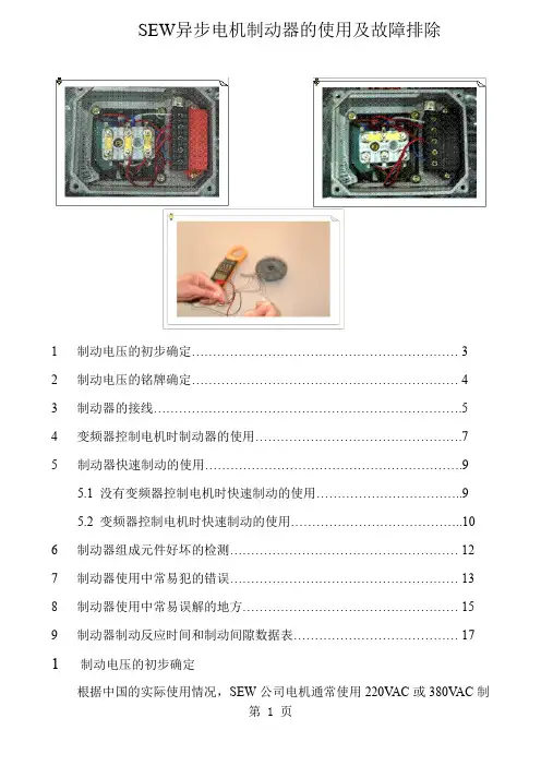
SEW异步电机制动器的使用及故障排除1 制动电压的初步确定 (3)2 制动电压的铭牌确定 (4)3 制动器的接线 (5)4 变频器控制电机时制动器的使用 (7)5制动器快速制动的使用 (9)5.1 没有变频器控制电机时快速制动的使用 (9)5.2 变频器控制电机时快速制动的使用 (10)6 制动器组成元件好坏的检测 (12)7 制动器使用中常易犯的错误 (13)8 制动器使用中常易误解的地方 (15)9 制动器制动反应时间和制动间隙数据表 (17)1 制动电压的初步确定根据中国的实际使用情况,SEW公司电机通常使用220VAC或380VAC制动电压的制动器,如果客户定货时没有指明制动电压的要求,SEW公司将按以下原则配置制动器的制动电压,机座号63—100的电机配置220VAC制动电压的制动器;机座号112以上的电机配置380VAC制动电压的制动器;(电机机座号与电机功率对照表见SEW《电机技术手册》)对于最常使用的4级电机而言,0.12Kw—3Kw的电机配置220VAC制动电压的制动器(0.12Kw电机有56机座号和63机座号两种,56机座号除外);4Kw以上的电机配置380VAC制动电压的制动器。
当然,客户也可指明制动器制动电压的等级,电气设计人员为方便控制的要求,最好能与机械设计人员协商,指明制动器制动电压的等级。
2 制动电压的铭牌确定电机的铭牌上左下脚标明了所配制动器制动电压的等级,请以此为准配置正确的制动电压。
3制动器的接线对于单速电机,为方便客户使用,在电机出厂时SEW公司已将制动器控制电源接好,电源直接从电机接线柱上引取,当电机得电时电机运转,制动器也同时释放,当电机断电时电机停转,制动器也同时锁紧。
当使用机座号63--100的电机,电机通常为△/Y 220VAC/380VAC当使用机座号112以上的电机(包括112机座),电机通常为△/Y 380VAC/660VAC见下图1)机座号63—100的单速电机2)机座号112以上的单速电机4变频器控制电机时制动器的使用首先应将从电机接线柱上接到制动整流块上的电源线拆除,单独给制动整流块引取电源,见下图1)机座号63—100的单速电机2)机座号112以上的单速电机5制动器快速制动的使用通过改变制动整流块的接线方式,可使制动器变为快速制动运行,制动速度为普通制动的5倍以上,在驱动控制中可提高定位精度;在升降驱动中,如提升机,叉式升降机等建议使用快速制动。
盘式制动器制动间隙调整测量方法盘式制动器制动间隙调整测量方法为确保前轴盘式制动器正确使用,现对前轴盘式制动器制动间隙的制动间隙的测测量方法进一步明确规范,请认真参阅执行。
测量制动间隙前,应首应首先先活塞总成)可以正常工作。
本确认间隙自动调整机构((AZ9100443500AZ9100443500AZ9100443500活塞总成)文首先表述如何判断活塞总成是否可靠工作,再进一步说明制动间再进一步说明制动间隙隙的测量方法。
(盘式制动器外形)外形)//(各部件名称)判断活塞总成是否有效:1、用SW10SW10扳手逆时针转动手调轴至极限位置(大体上逆时针旋转扳手逆时针转动手调轴至极限位置(大体上逆时针旋转扳手逆时针转动手调轴至极限位置(大体上逆时针旋转两两周),而后反向微调少许(以防螺纹发卡),而后反向微调少许(以防螺纹发卡);;2、在气压足够大的情况下,原地连续踩刹车、在气压足够大的情况下,原地连续踩刹车101010次左右。
注意:踩刹次左右。
注意:踩刹车时将扳手扣在手调轴上,以观察刹车时手调轴是否转动,正常现正常现象象应该是开始几次制动时扳手转动(顺时针)角度较大,越来越小,最后稳定到某个角度,此时即表明间隙已经调整到设计值。
如果踩刹如果踩刹车车时手调轴不转动或者有逆时针转动状况,则该自动调整机构(活塞(活塞总总成)已不能正常工作,必须更换。
图一图一//图二图二//图三制动间隙的测量:盘式制动器从设计结构上已设定了制动间隙,并且制动间隙是自动并且制动间隙是自动调调整的,不允许人为调整,制动间隙在0.80.8~~1.0mm 范围内是正常的。
如果整车使用过程中出现左右制动力差值偏大、制动力不足或制动制动力不足或制动过过热等故障现象时,可按如下步骤检查制动间隙:1、拆下压板(如塞尺插入方便可不拆压板),向箭头所指方向推动向箭头所指方向推动钳钳体,使外侧制动块与制动盘紧密结合。
(图一)2、拨动内侧制动块使其靠近制动盘,测量间隙活塞总成整体推盘与制动块背板之间的间隙。
11.3Principles of the SEW brake 1.3.1Principles of project planning The SEW brake is a DC-operated electromagnetic disc brake with a DC coil which is opened electri-cally and braked using spring force. The system satisfies fundamental safety requirements: the brake is applied if the power fails.The principal parts of the brake system are the brake coil itself (accelerator coil + coil section =holding coil), consisting of the brake coil body (9) with an encapsulated winding and a tap (8), the moving pressure plate (6), the brake springs (7), the brake disc (1) and the brake bearing end shield (2).The significant feature of SEW brakes is their very short length: the brake bearing end shield is a part of both the motor and the brake. The integrated construction of the SEW brake motor permits particularly compact and sturdy solutions.00871AXX Fig. 1: Block diagram of the brake 1Brake disc 2Brake bearing end shield 3Carrier 4Spring force 5Working air gap 6Pressure plate 7Brake spring 8Brake coil 9 Brake coil body 10Motor shaft 11 Electromagnetic force 511109876321411.3.2Basic functionIn contrast to other DC-operated disc brakes, SEW brakes operate with a two coil system. The pressure plate is forced against the brake disc by the brake springs when the electromagnet is de-energized. The motor is braked. The number and type of the brake springs determine the braking torque.When the brake coil is connected to the appropriate DC voltage, the spring force (4) is overcome by magnetic force (11), thereby bringing the pressure plate into contact with the brake coil body.The brake disc moves clear and the rotor can turn.Particularly short response times When switching on:A special brake control system ensures that only the accelerator coil is switched on first followed by the holding coil (entire coil). The powerful impulse magnetization (high acceleration current) of the accelerator coil produces an especially short response time, particularly in large brakes, with-out however reaching the saturation limit (→ Fig. 2). The brake disc moves clear very swiftly and the motor starts up with hardly any braking losses.00868AENFig. 2: Functional principles of the two coil brake BS Accelerator coil 1) Brake I BAcceleration currentTS Coil section 2) Brake control system I H Holding current BS + TS = Holding coil M 3TSBS1)2)V AC01873AEN120msI BtI HAcceleration Holding1The particularly rapid response times of SEW brakes add up to a shorter motor startup time, mini-mum startup heating and therefore less energy consumption and negligible brake wear during startup (→ Fig. 3). These factors pay dividends to the user in the form of an extremely high starting frequency and long brake service life.00869AXX Fig. 3: Shortening the motor startup time with the SEW brake system The system switches over to the holding coil electronically as soon as the SEW brake has released.The braking magnet is now only sufficiently magnetized (with a small holding current) to ensure that the pressure plate is held in the startup position with adequate security and with minimum brake heating (→ Fig. 2).I S Coil current M B Braking torque n Speed t 1Brake response time 1)Switch-on procedure for operation with a rectifier without switching electron-ics 2)Switch-on procedure for operation with SEW rectifier with switching electronics, e.g. BGE (standard from size 112 upwards)t 1t 1t t t t t t I S I S M B M B n n 1)2)1When switching off:This means de-excitation occurs very rapidly when the coil is switched off, so the brake is applied with an extremely rapid reaction time, particularly with large brakes. This offers benefits to the user in the form of an especially short braking distance with a high repeat accuracy and high level of security, e.g. for applications involving drive units for vertical motion.00872AXXFig. 4: Shortening the braking distance by brake cut-off in the DC and AC circuitsThe response time for application of the brake is also dependent on how rapidly the energy stored in the brake coil can be dissipated when the electrical power is switched off. A free-wheeling diode is used for dissipating the energy for a “cut-off in the AC circuit”. The current decays according to an e-function.The current decays much more rapidly via the varistor when the DC circuit of the coil is interrupted at the same time, giving “cut-off in the DC and AC circuits”. The response time is significantly shorter (→ Fig. 4, Fig. 5). Conventionally, “cut-off in the DC and AC circuits” is implemented using an additional contact on the brake contactor (suitable for DC switching).Under certain circumstances, it is beneficial to use the electronic relays SR and UR (→ Sec.2.2.2.2) for interrupting the DC circuit.I S Coil current M B Braking torque n Speedt 2Normal brake reaction time1)Brake reaction to cut-off in the AC circuit 2)Brake reaction to cut-off in the DC and AC circuitst t t I S M B n 1)2)t 2t 2I SM Bnttt→ Sec.10001240ADE Fig. 5: Principles of cut-off in the DC and AC circuits Particularly quiet Particularly quiet brake motors are demanded in many applications in the power range up to approx. 5.5 kW in order to reduce noise pollution. SEW satisfies these conditions as standard in all brake motors up to size 132S by means of appropriate design features, without affecting the partic-ular dynamic properties of the brake system.Particularly safe The excitation power needed for the holding function may be too small in the event of a power fail-ure or especially severe voltage dips. The brake is applied for reasons of safety. A monitoring sys-tem ensures that the accelerator coil is reactivated when the voltage returns, thereby releasing the brake.AC M 3TS BS V11.7Working air gap with SEW brakes 1) Double disc brake Motor size Brake type Working air gap (mm)New setting Readjust at 6371/808090/100100B03BMG05, BC05BMG1, BC05BMG2, BC2BMG4, BC2min. 0.25max. 0.6112/132S 132M/160M 160L/180200/225BMG8BM15BM30BM31min. 0.3max. 1.2180200/225BM321)BM621)min. 0.4max. 1.2。
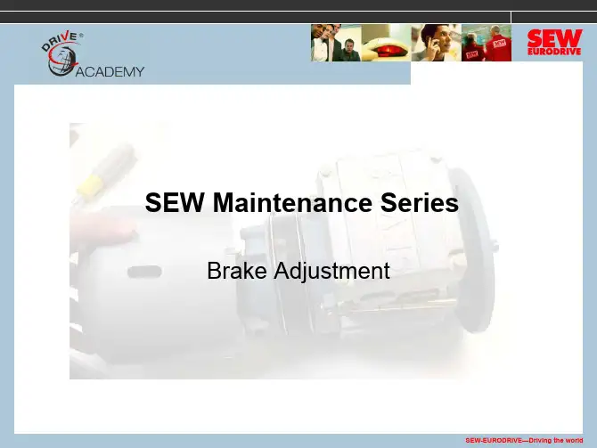
SEW 制动器间隙调整指导说明
SEW 制动电机的制动器是采用双直流线圈设计,具有快速吸合、制动盘磨损小之优点,同时结构紧凑,调整间隙简单,适用于各种工况;
SEW 制动器出厂前设定制动间隙在0.4mm (采用塞尺沿线圈本体周边检测),制动器工作间隙正常范围(0.4mm-1.2mm),制动工作间隙范围宽,调整周期长;
若制动器动作异常,需要检查制动器电源是否供电正常(370VAC-414VAC ),并检查制动工作间隙有无异常磨损变化,当检测工作间隙大于1.2mm 用1.25mm 塞尺检查线圈本体和金属压盘之间工作间隙,若确认间隙大于1.2mm ,则需重新调整制动器工作间隙;
图1制动器间隙 图2 调整塞尺
1制动盘
2后端盖
3花键
4弹簧作用力方向
5制动间隙A
6金属压盘
7制动弹簧
8制动线圈
9线圈载体
10电机轴
11电磁作用力方向 工作间隙
0.4mm
图3 图4 调整间隙及手动释放方法:
1、采用19开口扳手顺时针旋转定位隔套b 约2圈,将三个定位隔套b 旋入后端盖约1.6mm ,采用22开口扳手顺时针旋转固定螺帽a ,依次均匀拧紧三个螺母a ,用0.4mm 塞尺插入线圈和金属压盘间,沿线圈圆周均匀检测,直至0.45mm 塞尺不进即可;
2、间隙检测完成,再依次反时针旋出三个定位隔套b ,拧出隔套b ,将螺帽a 和隔套b 锁紧线圈本体,线圈固定完成;
3、单个制动盘出厂标准厚度是14mm ,当其磨损后厚度低于10mm 后就需要更换;
4、在制动器没有通电情况下,可手动释放制动器(即顺时针旋转释放顶丝c ,将金属压盘带向线圈本体方向,让两者间工作间隙调整为零间隙,制动器手动释放,此时可灵活转动电机轴,满足检查、调试要求。